WO2014050163A1 - ガスタービン冷却系統の制御方法、この方法を実行する制御装置、これを備えているガスタービン設備 - Google Patents
ガスタービン冷却系統の制御方法、この方法を実行する制御装置、これを備えているガスタービン設備 Download PDFInfo
- Publication number
- WO2014050163A1 WO2014050163A1 PCT/JP2013/054727 JP2013054727W WO2014050163A1 WO 2014050163 A1 WO2014050163 A1 WO 2014050163A1 JP 2013054727 W JP2013054727 W JP 2013054727W WO 2014050163 A1 WO2014050163 A1 WO 2014050163A1
- Authority
- WO
- WIPO (PCT)
- Prior art keywords
- gas turbine
- cooling air
- temperature
- target value
- drive amount
- Prior art date
- Legal status (The legal status is an assumption and is not a legal conclusion. Google has not performed a legal analysis and makes no representation as to the accuracy of the status listed.)
- Ceased
Links
Images



Classifications
-
- F—MECHANICAL ENGINEERING; LIGHTING; HEATING; WEAPONS; BLASTING
- F01—MACHINES OR ENGINES IN GENERAL; ENGINE PLANTS IN GENERAL; STEAM ENGINES
- F01K—STEAM ENGINE PLANTS; STEAM ACCUMULATORS; ENGINE PLANTS NOT OTHERWISE PROVIDED FOR; ENGINES USING SPECIAL WORKING FLUIDS OR CYCLES
- F01K19/00—Regenerating or otherwise treating steam exhausted from steam engine plant
- F01K19/10—Cooling exhaust steam other than by condenser; Rendering exhaust steam invisible
-
- F—MECHANICAL ENGINEERING; LIGHTING; HEATING; WEAPONS; BLASTING
- F01—MACHINES OR ENGINES IN GENERAL; ENGINE PLANTS IN GENERAL; STEAM ENGINES
- F01D—NON-POSITIVE DISPLACEMENT MACHINES OR ENGINES, e.g. STEAM TURBINES
- F01D25/00—Component parts, details, or accessories, not provided for in, or of interest apart from, other groups
- F01D25/08—Cooling; Heating; Heat-insulation
- F01D25/12—Cooling
-
- F—MECHANICAL ENGINEERING; LIGHTING; HEATING; WEAPONS; BLASTING
- F01—MACHINES OR ENGINES IN GENERAL; ENGINE PLANTS IN GENERAL; STEAM ENGINES
- F01K—STEAM ENGINE PLANTS; STEAM ACCUMULATORS; ENGINE PLANTS NOT OTHERWISE PROVIDED FOR; ENGINES USING SPECIAL WORKING FLUIDS OR CYCLES
- F01K23/00—Plants characterised by more than one engine delivering power external to the plant, the engines being driven by different fluids
- F01K23/02—Plants characterised by more than one engine delivering power external to the plant, the engines being driven by different fluids the engine cycles being thermally coupled
- F01K23/06—Plants characterised by more than one engine delivering power external to the plant, the engines being driven by different fluids the engine cycles being thermally coupled combustion heat from one cycle heating the fluid in another cycle
- F01K23/10—Plants characterised by more than one engine delivering power external to the plant, the engines being driven by different fluids the engine cycles being thermally coupled combustion heat from one cycle heating the fluid in another cycle with exhaust fluid of one cycle heating the fluid in another cycle
-
- F—MECHANICAL ENGINEERING; LIGHTING; HEATING; WEAPONS; BLASTING
- F02—COMBUSTION ENGINES; HOT-GAS OR COMBUSTION-PRODUCT ENGINE PLANTS
- F02C—GAS-TURBINE PLANTS; AIR INTAKES FOR JET-PROPULSION PLANTS; CONTROLLING FUEL SUPPLY IN AIR-BREATHING JET-PROPULSION PLANTS
- F02C6/00—Plural gas-turbine plants; Combinations of gas-turbine plants with other apparatus; Adaptations of gas-turbine plants for special use
- F02C6/18—Plural gas-turbine plants; Combinations of gas-turbine plants with other apparatus; Adaptations of gas-turbine plants for special use using the waste heat of gas-turbine plants outside the plants themselves, e.g. gas-turbine power heat plants
-
- F—MECHANICAL ENGINEERING; LIGHTING; HEATING; WEAPONS; BLASTING
- F02—COMBUSTION ENGINES; HOT-GAS OR COMBUSTION-PRODUCT ENGINE PLANTS
- F02C—GAS-TURBINE PLANTS; AIR INTAKES FOR JET-PROPULSION PLANTS; CONTROLLING FUEL SUPPLY IN AIR-BREATHING JET-PROPULSION PLANTS
- F02C7/00—Features, components parts, details or accessories, not provided for in, or of interest apart form groups F02C1/00 - F02C6/00; Air intakes for jet-propulsion plants
- F02C7/12—Cooling of plants
- F02C7/14—Cooling of plants of fluids in the plant, e.g. lubricant or fuel
- F02C7/141—Cooling of plants of fluids in the plant, e.g. lubricant or fuel of working fluid
- F02C7/143—Cooling of plants of fluids in the plant, e.g. lubricant or fuel of working fluid before or between the compressor stages
-
- F—MECHANICAL ENGINEERING; LIGHTING; HEATING; WEAPONS; BLASTING
- F02—COMBUSTION ENGINES; HOT-GAS OR COMBUSTION-PRODUCT ENGINE PLANTS
- F02C—GAS-TURBINE PLANTS; AIR INTAKES FOR JET-PROPULSION PLANTS; CONTROLLING FUEL SUPPLY IN AIR-BREATHING JET-PROPULSION PLANTS
- F02C7/00—Features, components parts, details or accessories, not provided for in, or of interest apart form groups F02C1/00 - F02C6/00; Air intakes for jet-propulsion plants
- F02C7/12—Cooling of plants
- F02C7/16—Cooling of plants characterised by cooling medium
- F02C7/18—Cooling of plants characterised by cooling medium the medium being gaseous, e.g. air
- F02C7/185—Cooling means for reducing the temperature of the cooling air or gas
-
- F—MECHANICAL ENGINEERING; LIGHTING; HEATING; WEAPONS; BLASTING
- F02—COMBUSTION ENGINES; HOT-GAS OR COMBUSTION-PRODUCT ENGINE PLANTS
- F02C—GAS-TURBINE PLANTS; AIR INTAKES FOR JET-PROPULSION PLANTS; CONTROLLING FUEL SUPPLY IN AIR-BREATHING JET-PROPULSION PLANTS
- F02C9/00—Controlling gas-turbine plants; Controlling fuel supply in air- breathing jet-propulsion plants
- F02C9/16—Control of working fluid flow
- F02C9/18—Control of working fluid flow by bleeding, bypassing or acting on variable working fluid interconnections between turbines or compressors or their stages
Definitions
- the present invention relates to a control method of a gas turbine cooling system for cooling a high-temperature portion in contact with a combustion gas in a gas turbine, a control device for executing the method, and a gas turbine facility including the control device.
- the gas turbine includes an air compressor that compresses outside air to generate compressed air, a plurality of combustors that generate combustion gas by burning fuel in the compressed air, and a turbine that is driven by the combustion gas.
- the combustion cylinder of the combustor, the moving blades and stationary blades of the turbine, etc. are exposed to high-temperature combustion gas. Therefore, these high-temperature parts are cooled to protect these high-temperature parts from the heat of the combustion gas. There is a need.
- Patent Document 1 discloses a cooling system for cooling a tail cylinder (combustion cylinder) of a combustor that is a part of a high temperature portion of a gas turbine.
- This cooling system includes a cooler that cools the compressed air extracted from the air compressor, and pressurizes the compressed air cooled by the cooler, and sends the compressed air as cooling air to the combustor tail pipe. And a compressor.
- the present invention executes a method for controlling a gas turbine cooling system capable of sufficiently cooling a high temperature portion of a gas turbine and improving the power generation efficiency of the gas turbine. It aims at providing a control device and gas turbine equipment provided with this.
- a control method for a gas turbine cooling system includes a cooler that cools compressed air extracted from an air compressor of a gas turbine to form cooling air, and the cooling air is a combustion gas in the gas turbine.
- a cooling air compressor that supplies a high-temperature portion that is in contact with the gas turbine cooling system, and a target value for the flow-air equivalent value of the cooling air that is supplied to the high-temperature portion and a temperature of the cooling air
- a target value setting step for determining a target value in accordance with the detected temperature of the cooling air using a target value setting function that defines the relationship of the above, and a correction drive of the cooling air amount regulator for adjusting the flow rate of the cooling air
- a correction drive quantity calculation step for obtaining a correction drive quantity that reduces a deviation of the detected flow rate equivalent value of the cooling air from the target value, and a drive according to the correction drive quantity
- the driving amount of the cooling air amount adjuster is adjusted so that the value corresponding to the flow rate of the cooling air becomes the target value, the flow rate of the cooling air sent to the high temperature part of the gas turbine becomes almost the target value.
- the target value of the flow rate corresponding value is determined according to the temperature of the cooling air sent to the high temperature part, and the flow rate of the cooling air is controlled by controlling the flow rate equivalent value to be this target value.
- the high temperature part is controlled to be equal to or lower than a predetermined temperature by setting the target value of the flow rate according to the temperature of the cooling air. Moreover, in the said control method, since it is not necessary to increase the cooling air sent to a high temperature part unnecessarily, the electric power generation efficiency of a gas turbine can be improved.
- the target value setting function defines a relationship between the target value, the temperature of the cooling air, and a gas turbine output equivalent value, and in the target value setting step, the target value A target value may be determined according to the detected temperature of the cooling air and the value corresponding to the gas turbine output obtained from the outside using a setting function.
- the detected temperature of the cooling air using a driving amount setting function indicating a relationship between the temperature of the cooling air and the driving amount of the cooling air amount adjuster.
- a preceding drive amount setting step for determining a preceding drive amount in accordance with the drive amount, and in the drive command output step, the drive amount added to the corrected drive amount to the preceding drive amount determined in the preceding drive amount setting step A drive command may be output.
- the drive amount setting function defines the relationship between the cooling air temperature, the gas turbine output equivalent value, and the drive amount of the cooling air amount adjuster.
- the preceding drive amount may be determined according to the detected temperature of the cooling air and the value corresponding to the gas turbine output obtained from the outside using a drive amount setting function.
- a control apparatus for a gas turbine cooling system includes a cooler that cools compressed air extracted from an air compressor of a gas turbine to cool it, and the cooling air is combustion gas in the gas turbine.
- a control unit for a gas turbine cooling system that includes a cooling air compressor that is supplied to a high-temperature portion that is in contact with the target, and a target that defines a relationship between a target value for a flow rate equivalent value of the cooling air and a temperature of the cooling air
- a target value setting unit that determines a target value according to the detected temperature of the cooling air using a value setting function, and the target value as a correction drive amount of a cooling air amount regulator that adjusts the flow rate of the cooling air
- a correction drive amount calculation unit for obtaining a correction drive amount for which a deviation of the detected value corresponding to the flow rate of the cooling air is small, and a drive command according to the correction drive amount is adjusted for the cooling air amount Having a drive command output unit for outputting to.
- a target value of a flow rate corresponding value is determined according to the temperature of the cooling air sent to the high temperature portion, and control is performed so that the flow rate equivalent value becomes this target value. Therefore, the flow rate of the cooling air can be set to the target value of the flow rate according to the temperature of the cooling air, and the high temperature part can be managed to be equal to or lower than the predetermined temperature. Furthermore, the power generation efficiency of the gas turbine can be improved.
- the target value setting function defines a relationship between the target value, a temperature of the cooling air, and a gas turbine output equivalent value
- the target value setting unit includes the target value
- a target value may be determined according to the detected temperature of the cooling air and the value corresponding to the gas turbine output obtained from the outside using a setting function.
- the control device since the target value corresponding to the gas turbine output equivalent value is set, even if the gas turbine output equivalent value becomes high and the amount of heat for heating the high temperature part increases, the high temperature part is managed below a predetermined temperature. be able to.
- the target value setting function may be a function indicating a relationship in which the target value increases as the temperature of the cooling air increases.
- the detected temperature of the cooling air using a drive amount setting function indicating the relationship between the temperature of the cooling air and the drive amount of the cooling air amount adjuster.
- a preceding drive amount setting unit that determines a preceding drive amount according to the driving command output unit according to a drive amount obtained by adding the correction drive amount to the preceding drive amount determined by the preceding drive amount setting unit A drive command may be output.
- the drive amount setting function defines the relationship between the temperature of the cooling air, the gas turbine output equivalent value, and the drive amount of the cooling air amount adjuster, and the preceding drive amount setting unit
- a drive amount setting function may be used to determine the preceding drive amount according to the detected temperature of the cooling air and the gas turbine output equivalent value obtained from the outside.
- control device by performing the advance control using the advance drive amount, it is possible to improve the responsiveness of the change of the cooling air flow rate due to the variation of various parameters.
- the gas turbine equipment detects any one of the above control devices, a thermometer for detecting the temperature of the cooling air supplied to the high temperature section, and the flow rate equivalent value of the cooling air.
- the gas turbine cooling system including the flow rate equivalent value meter, the cooler, the cooling air compressor, and the cooling air amount adjuster, and the gas turbine.
- the flow rate of the cooling air can be set to a target value of the flow rate according to the temperature of the cooling air, and the high temperature portion is below a predetermined temperature. Can be managed. Furthermore, the power generation efficiency of the gas turbine can be improved.
- the cooler includes a heat exchanger that exchanges heat between the compressed air from the air compressor and a cooling medium, and a medium amount adjuster that adjusts the flow rate of the cooling medium
- the control device is a drive that outputs a drive command to the medium amount adjuster so that the temperature of the cooling air supplied to the high temperature portion becomes a temperature target value that is a target value of the temperature of the cooling air. You may have a command output part.
- the control device externally uses a temperature target value setting function indicating a relationship between a temperature target value that is a target value of the temperature of the cooling air supplied to the high temperature portion and a gas turbine output equivalent value.
- a temperature target value setting function indicating a relationship between a temperature target value that is a target value of the temperature of the cooling air supplied to the high temperature portion and a gas turbine output equivalent value.
- You may have the temperature target value setting part which determines the said temperature target value according to the obtained said gas turbine output equivalent value.
- the heat exchanger of the cooler is a radiator that exchanges heat with the compressed air as air as the cooling medium
- the cooler of the cooler The medium amount adjuster may be a fan capable of adjusting a flow rate of the air sent to the radiator.
- the gas turbine equipment may include a fuel preheater that heats the fuel by exchanging heat between the air sent from the fan to the radiator and the fuel sent to the combustor of the gas turbine. .
- the power generation efficiency of the gas turbine can be improved.
- an exhaust heat recovery boiler that generates steam by heat exchange with the combustion gas exhausted from the gas turbine, air sent from the fan to the radiator, and fuel sent to the combustor of the gas turbine, A first fuel preheater that heats the fuel, and a second fuel preheater that heats the fuel by exchanging heat between the fuel and steam generated by the exhaust heat recovery boiler or heated water. And a vessel. In the gas turbine facility, the power generation efficiency of the gas turbine can be increased.
- the cooler includes an exhaust heat recovery boiler that generates steam by heat exchange with the combustion gas exhausted from the gas turbine, and the heat of the cooler
- the exchanger is a boiler water preheater that exchanges heat sent to the exhaust heat recovery boiler with the compressed air as the cooling medium, and the medium amount regulator of the cooler sends the boiler water preheater to the boiler water preheater
- a water amount controller that adjusts the flow rate of water may be used.
- the compressed air can be cooled and the power generation efficiency of the gas turbine can be improved.
- the temperature of the high temperature portion of the gas turbine can be suppressed to a predetermined value or less, and the power generation efficiency of the gas turbine can be improved.
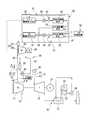
- the gas turbine equipment of the present embodiment includes a gas turbine 10, an exhaust heat recovery device 20 that recovers heat of combustion gas exhausted from the gas turbine 10, and a high-temperature portion in the gas turbine 10.
- a gas turbine cooling system (hereinafter simply referred to as a cooling system) 30 for cooling, a control device 50 for controlling the cooling system 30, and a host control device 70 are provided.
- the gas turbine 10 includes an air compressor 11 that compresses outside air to generate compressed air, a plurality of combustors 12 that generate fuel gas by burning fuel F from a fuel supply source in the compressed air, and a combustion gas. And a turbine 15 driven by A generator 19 that generates electric power by rotation of the rotor is connected to the rotor of the turbine 15.
- the plurality of combustors 12 are fixed to the casing of the turbine 15 at equal intervals in the circumferential direction around the rotor of the turbine 15.
- the combustor 12 includes a combustion cylinder 13 that sends combustion gas into the combustion gas flow path of the turbine 15, and a fuel supplier 14 that injects fuel and compressed air into the combustion cylinder 13.
- the combustion cylinder 13 of the combustor 12 and the moving blades and stationary blades of the turbine 15 form a high-temperature portion that is exposed to high-temperature combustion gas.
- the cooling system 30 of the present embodiment supplies cooling air to the combustion cylinder 13 of the combustor 12 in the high temperature part of the gas turbine 10 to cool the combustion cylinder 13.
- the combustion cylinder 13 is formed with a cooling air passage that passes between the outer peripheral surface of the combustion cylinder 13 and the inner peripheral surface thereof.
- the cooling air passages are open to the upstream side and the downstream side in the combustion gas flow direction on the outer peripheral side of the combustion cylinder 13.
- An opening on the downstream side in the flow direction of the combustion gas in the combustion cylinder 13 forms an inlet for cooling air, and an opening on the upstream side in the flow direction of combustion gas forms an outlet for cooling air.
- the cooling air that has flowed into the cooling air passage from the downstream opening in the combustion gas flow direction in the combustion cylinder 13 cools the wall surface of the combustion cylinder 13 and then the upstream opening in the combustion gas flow direction in the combustion cylinder 13. And is recovered by the combustor 12 as combustion air.
- the exhaust heat recovery device 20 includes an exhaust heat recovery boiler 21 that generates steam by heat exchange between the combustion gas exhausted from the gas turbine 10 and water, and a steam turbine 22 that is driven by the steam generated in the exhaust heat recovery boiler 21. , A condenser 23 that returns the steam that has driven the steam turbine 22 to water, and a water supply pump 24 that returns the water in the condenser 23 to the exhaust heat recovery boiler 21.
- a generator that generates electric power by rotating the rotor is connected to the rotor of the steam turbine 22.
- the cooling system 30 includes a cooler 31 that cools compressed air extracted from the air compressor 11 of the gas turbine 10 to form cooling air, and pressurizes the cooling air to form compressed cooling air as a combustion cylinder 13 of the combustor 12. And a cooling air compressor 34 to be supplied.
- the pressurized cooling air may also be simply referred to as cooling air.
- the cooler 31 has a radiator 32 through which compressed air extracted from the air compressor 11 passes and a fan 33 that sends air to the radiator 32.
- the fan 33 has an inverter-equipped motor, and the air flow rate can be adjusted by changing the rotation speed of the inverter-equipped motor.
- the fan 33 is a medium amount adjuster that can adjust the flow rate of air that is a cooling medium for compressed air.
- a fuel preheater 49 is installed at a position adjacent to the radiator 32, and the fuel preheater 49 is heated by heat exchange with the compressed air in the radiator 32 and fuel F supplied to the combustor 12. And the fuel F is heated.
- the motor 38 is connected to the cooling air compressor 34, and the cooling air compressor 34 is driven by driving the motor 38.
- a motor is used as a driving source of the cooling air compressor 34.
- the driving source of the cooling air compressor 34 may be any, for example, mechanically connected to the air compressor 11 of the gas turbine 10 or the rotor of the turbine 15 to connect the air compressor 11 or the turbine 15 to the driving source. It is good.
- An IGV (inlet guide vane) 35 as a cooling air flow rate regulator for adjusting the flow rate of the sucked air is provided at the suction port of the cooling air compressor 34.
- the IGV 35 includes a vane 36 disposed in the suction port of the cooling air compressor 34 and a driver 37 that changes the angle of the vane 36.
- the compressed air line 41 for cooling branches in the middle.
- a radiator 32 of the cooler 31 is connected to the cooling compressed air line 41.
- the radiator 32 and the suction port of the cooling air compressor 34 are connected by a cooling air line 42.
- the discharge port of the cooling air compressor 34 and the combustion cylinder 13 of the combustor 12 are connected by a pressurized cooling air line 43.
- the cooling system 30 of the present embodiment further includes a thermometer 45 that detects the temperature of the pressurized cooling air passing through the pressurized cooling air line 43, the pressure of the compressed air in the compressed air line for cooling 41, and the pressurized cooling air.
- the control device 50 includes an IGV control system 51 that controls the vane opening degree of the IGV 35 as a cooling air flow rate regulator, a fan control system 61 that controls the rotation speed of the fan 33 as a medium amount regulator in the cooler 31, A compressor control system (not shown) that activates a motor 38 or the like that is a drive source of the cooling air compressor 34.
- the IGV control system 51 outputs a drive command indicating the drive amount (IGV opening) of the driver 37 to the driver 37 of the IGV 35.
- This IGV control system 51 includes a differential pressure target value setting unit that determines a target value of a differential pressure ⁇ P between the pressure of compressed air in the compressed air line for cooling 41 and the pressure of pressurized cooling air in the pressurized cooling air line 43.
- the correction drive amount calculation unit includes a subtractor 53 and a PI controller 54.
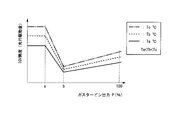
- the differential pressure target value setting unit 52 indicates the relationship between the differential pressure target value, the gas turbine output P, and the temperature T of the pressurized cooling air detected by the thermometer 45. It has a value setting function.
- This differential pressure target value setting function is a function in which the differential pressure target value increases as the temperature T (Ta ⁇ Tb ⁇ Tc) of the pressurized cooling air increases.
- the differential pressure target value setting function is a function that increases the differential pressure target value as the gas turbine output P increases when the gas turbine output P is, for example, about 50% medium output (b%) or more. is there.
- the differential pressure target value setting unit 52 uses the differential pressure target value setting function to convert the gas turbine output P obtained from the host controller 70 and the temperature T of the pressurized cooling air detected by the thermometer 45. A differential pressure target value is determined.
- the value of the gas turbine output P is sent from, for example, the host control device 70.
- the host controller 70 treats the value of the power detected by a power meter or the like that detects the generated power of the generator 19 connected to the gas turbine 10 as the value of the gas turbine output P.
- the preceding drive amount setting unit 55 shows the relationship between the advance drive amount (IGV opening), the gas turbine output P, and the temperature T of the pressurized cooling air detected by the thermometer 45. It has a preceding drive amount setting function.
- This set drive amount setting function is a function in which the preceding drive amount increases as the temperature T (Ta ⁇ Tb ⁇ Tc) of the pressurized cooling air increases.
- the preceding drive amount setting function indicates that the preceding drive amount is the maximum at the pressurized air temperature and the gas turbine output P is 0% to a predetermined low output (a%). It is a function indicating a constant value.
- the preceding drive amount setting function is such that when the temperature of the pressurized cooling air is constant, the gas turbine output P is high from the low output (a%) to the above-described medium output (b%) when the gas turbine output P is low. As a result, this is a function that decreases the preceding drive amount. Further, the preceding drive amount setting function is such that when the temperature of the pressurized cooling air is constant, if the gas turbine output P is equal to or higher than the medium output (b%), the preceding drive amount increases as the gas turbine output P increases. A function that grows.
- the preceding drive amount setting unit 55 uses the preceding drive amount setting function to perform the preceding according to the gas turbine output P obtained from the host controller 70 and the temperature T of the pressurized cooling air detected by the thermometer 45. Determine the driving amount.
- the fan control system 61 outputs a drive command indicating the drive amount (rotation speed) of the fan 33 to the fan 33.
- the fan control system 61 includes a temperature target value setting unit 62 that determines a target value of the temperature T of the pressurized cooling air detected by the thermometer 45, and the temperature T and the temperature target of the pressurized cooling air detected by the thermometer 45.
- a subtractor 63 for obtaining a deviation from the value
- a PI controller 64 for obtaining a correction drive amount for proportional / integral operation corresponding to the deviation
- a fan drive for outputting a drive command corresponding to the correction drive amount to the fan 33
- a command output unit 65 As shown in FIG.
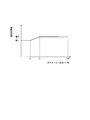
- the temperature target value setting unit 62 has a temperature target value setting function indicating the relationship between the temperature target value and the temperature T of the pressurized cooling air detected by the thermometer 45.
- This temperature target value setting function shows the first temperature target value where the temperature target value is constant from 0% to the aforementioned low output (a%), and the gas turbine output P is the medium output described above. Above (b%), it is a function that indicates a second temperature target value that is constant and higher than the first temperature target value.
- this temperature target value setting function is a function in which the temperature target value increases as the gas turbine output P increases from the low output (a%) to the medium output (b%).
- the temperature target value setting unit 62 uses this temperature target value setting function to determine a temperature target value according to the temperature T of the pressurized cooling air detected by the thermometer 45.
- differential pressure target value setting function may be in the form of expressing the relationship between each parameter in the form of a plurality of numerical values for each of a plurality of parameters. May be in the form of a table in which
- the starter starts to rotate the rotor of the turbine 15 and the rotor of the air compressor 11 (S1), and gradually increases their rotational speed.
- the pressure of the compressed air discharged from the air compressor 11 gradually increases and the temperature of the compressed air also gradually increases.
- the cooling air compressor 34 is activated by an instruction from a compressor control system (not shown) of the control device 50, and the control device
- the vane 36 of the IGV 35 starts to open in response to the drive command from the 50 IGV control system 51 (S2).
- the opening degree of the vane 36 of the IGV 35 (hereinafter simply referred to as the IGV opening degree) is fully open (100%), or the opening degree according to the temperature T detected by the thermometer 45 at that time.
- the maximum opening is reached (S3).
- the cooling air compressor 34 When the cooling air compressor 34 is started and the vane 36 of the IGV 35 starts to open (S2), the compressed air from the air compressor 11 passes through the cooling compressed air line 41, the cooling air line 42, and the pressurized cooling air line 43. Then, it is supplied to the combustion cylinder 13 of the combustor 12. At this time, the fan 33 of the cooler 31 has not been activated yet. At this stage, the cooler outlet temperature of the air, that is, the temperature of the air in the cooling air line 42 is substantially the same as the temperature of the compressed air immediately after being discharged from the air compressor 11. In addition, the air inlet temperature of the combustor 12, that is, the temperature in the pressurized cooling air line 43 detected by the thermometer 45, becomes higher than the cooler outlet temperature due to the pressurization by the cooling air compressor 34.
- the temperature of the cooling air in the cooling air line 42 that is, the cooler outlet temperature
- the temperature of the pressurized cooling air in the pressurized cooling air line 43 that is, the inlet temperature of the pressurized cooling air in the combustor
- the fan control system 61 of the control device 50 starts the fan 33 and starts controlling the rotational speed of the fan 33 as described above. (S5).
- the gas turbine output P0% is input from the host controller 70 to the temperature target value setting unit 62 of the fan control system 61.
- the temperature target value setting unit 62 outputs a first temperature target value that is a temperature target value of the pressurized cooling air corresponding to the gas turbine output P0%, using a temperature target value setting function (see FIG. 4).
- the subtractor 63 of the fan control system 61 obtains a deviation between the temperature T of the pressurized cooling air detected by the thermometer 45 and the first temperature target value, and outputs this to the PI controller 64 of the fan control system 61. .
- the PI controller 64 obtains a correction drive amount corresponding to the proportional / integral operation according to the deviation and outputs the correction drive amount to the fan drive command output unit 65.
- the fan drive command output unit 65 outputs a drive command corresponding to the corrected drive amount to the fan 33.
- the vane opening degree control of the IGV 35 is started by the IGV control system 51 of the control device 50 (S8).
- the preceding drive amount setting unit 55 of the IGV control system 51 receives the gas turbine output P from the host controller 70 and the temperature T of the pressurized cooling air detected by the thermometer 45.
- the preceding drive amount setting unit 55 determines a preceding drive amount corresponding to the gas turbine output P and the temperature T of the pressurized cooling air using the preceding drive amount setting function (see FIG. 3), and outputs this to the adder 56. To do.
- the differential pressure target value setting unit 52 of the IGV control system 51 also receives the gas turbine output P from the host controller 70 and the temperature T of the pressurized cooling air detected by the thermometer 45. Is done.
- the differential pressure target value setting unit 52 determines and outputs a differential pressure target value corresponding to the gas turbine output P and the temperature T of the pressurized cooling air using a differential pressure target value setting function (see FIG. 2). .
- the subtractor 53 of the IGV control system 51 obtains a deviation between the differential pressure target value and the differential pressure ⁇ P detected by the differential pressure gauge 46 and outputs this to the PI controller 54 of the IGV control system 51.
- the PI controller 54 obtains a correction drive amount corresponding to the proportional / integral operation according to the deviation, and outputs this to the adder 56.
- the adder 56 adds the preceding drive amount output from the preceding drive amount setting unit 55 and the corrected drive amount output from the PI controller 54, and outputs the drive amount obtained by this addition.
- the IGV drive command output unit 57 outputs a drive command corresponding to the drive amount output from the adder 56 to the driver 37 of the IGV 35.
- the IGV opening is an opening corresponding to the drive amount indicated by the drive command.
- the amount of advance driving of the IGV 35 is determined, the flow rate of the pressurized cooling air is feedforward controlled, and the pressure cooling is performed based on the differential pressure ⁇ P correlated with the flow rate of the pressurized cooling air. Feedback control of air flow rate.
- the preceding drive amount setting function indicates that the gas turbine output P increases as the gas turbine output P increases, as described above, from the low output (a%) to the medium output (b%). Thus, this is a function that decreases the preceding drive amount. For this reason, when the gas turbine output P is from the low output (a%) to the medium output (b%), the advance drive amount determined by this advance drive setting function is reached, and as the gas turbine output P increases, The IGV opening is reduced.
- the temperature target value setting function (see FIG. 4) of the fan control system 61 is as long as the gas turbine output P is from the low output (a%) to the medium output (b%). This is a function in which the temperature target value increases as the gas turbine output P increases. For this reason, when the gas turbine output P becomes low (a%), the temperature of the cooling air increases as the gas turbine output P increases from the low output (a%) to the medium output (b%). And the temperature of pressurized cooling air becomes high (S9).
- the preceding drive amount setting function (see FIG. 3) possessed by the IGV control system 51 indicates that the gas turbine output P increases as the gas turbine output P increases as described above when the gas turbine output P is greater than or equal to the medium output (b%). This is a function for increasing the preceding drive amount.
- the differential pressure target value setting function (FIG. 2) possessed by the IGV control system 51 indicates that the gas turbine output P becomes higher as described above when the gas turbine output P is equal to or higher than the medium output (b%). It is a function that increases the differential pressure target value. That is, when the gas turbine output P is equal to or higher than the medium output (b%), the preceding drive amount and the differential pressure target value increase as the gas turbine output P increases.
- the IGV opening increases as the gas turbine output P increases.
- the IGV opening becomes smaller as the gas turbine output P becomes lower (S10).
- the temperature target value setting function (see FIG. 4) of the fan control system 61 is a second temperature that is constant and higher than the first temperature target value when the gas turbine output P is medium output (b%) or more. It is a function indicating a target value. For this reason, when the gas turbine output P becomes equal to or higher than the medium output (b%), the temperature of the pressurized cooling air becomes substantially the second temperature target value (S11).
- the gas is controlled by the IGV control system 51.
- the opening degree of the vane 36 of the IGV 35 increases (S12), and as the gas turbine output P decreases as controlled by the fan control system 61, the temperature and pressure of the cooling air are increased. The temperature of the pressure cooling air is lowered (S13).
- the IGV opening becomes 100% again by the control by the IGV control system 51, or is detected by the thermometer 45 at that time.
- the maximum opening degree of the opening degree according to the temperature T is reached (S14), and the temperature of the pressurized cooling air becomes almost the first temperature target value again by the control by the fan control system 61 (S15). .
- the IGV opening is 0%, that is, fully closed by the control by the IGV control system 51 (S17),
- the cooling air compressor 34 is stopped, and the fan 33 is stopped under the control of the fan control system 61 (S18).
- the differential pressure ⁇ P with the pressure of the pressurized cooling air sent to is correlated with the flow rate of the cooling air sent to the combustion cylinder 13 of the combustor 12. For this reason, when the IGV opening is adjusted and the differential pressure ⁇ P is controlled to become the differential pressure target value, the flow rate of the cooling air sent to the combustion cylinder 13 of the combustor 12 is also a predetermined value corresponding to the differential pressure target value. It becomes flow rate.
- the combustion cylinder 13 can be managed within a predetermined temperature unless the flow rate can be controlled to match the temperature of the cooling air. Can not.
- the pressure differential cooling target value is determined in accordance with the temperature of the pressurized cooling air supplied to the combustion cylinder 13 and controlled so that the differential pressure ⁇ P becomes the target differential pressure ⁇ P.
- the flow rate of air is set to a target value corresponding to the temperature of the pressurized cooling air, and the temperature of the combustion cylinder 13 is controlled to a temperature that does not damage the combustion cylinder 13.
- the power generation efficiency of the gas turbine 10 can be improved.
- the gas turbine 10 When the gas turbine 10 reaches a medium output (b%) or more, the amount of fuel supplied to the gas turbine 10 increases, and when the gas turbine output P increases, the amount of heat for heating the combustion cylinder 13 increases. Therefore, in the present embodiment, as the gas turbine output P increases, the differential pressure target value is increased, the preceding drive amount of the IGV 35 is increased, and the flow rate of the pressurized cooling air supplied to the combustion cylinder 13 is increased. The increase in temperature of the combustion cylinder 13 is suppressed.
- feedback control of the flow rate of the pressurized cooling air is performed based on the differential pressure ⁇ P that is correlated with the flow rate of the pressurized cooling air, and the preceding drive amount of the IGV 35 is determined and added. Since feed-forward control is performed on the flow rate of the pressure cooling air, it is possible to improve the responsiveness of changing the flow rate of the pressurized cooling air that accompanies changes in various parameters such as the temperature of the pressurized cooling air and the gas turbine output P.
- the fuel supplied to the combustor 12 is supplied by the fuel preheater 49 using the heat of air blown from the fan 33 of the cooler 31 and heated by heat exchange with the compressed air. Since the preheating is performed, the power generation efficiency of the gas turbine 10 can be further improved.
- the pressure of the pressurized cooling air is lower than that during the load operation. Therefore, in this embodiment, in order to ensure the flow rate and temperature of the pressurized cooling air necessary for cooling the combustion cylinder 13 in the starting process and the stopping process, the IGV opening is fully opened (100%), or at that time The maximum opening degree of the opening degree corresponding to the temperature T detected by the thermometer 45 is reduced, and the temperature of the pressurized cooling air is lowered to increase the flow rate of the low-temperature pressurized cooling air. .
- the IGV opening is fully opened (100%) or the opening corresponding to the temperature T detected by the thermometer 45 without lowering the temperature of the pressurized cooling air. If the maximum opening is set, the combustion cylinder 13 of the combustor 12 can be cooled to a predetermined temperature or lower. However, if the temperature of the pressurized cooling air is not lowered, it becomes necessary to increase the flow rate of the pressurized cooling air. Therefore, the necessary intake air amount of the cooling air compressor 34 must be increased, and the cooling air compressor The size of 34 increases, and the equipment cost increases. Therefore, in the present embodiment, the required intake air volume of the cooling air compressor 34 is reduced by lowering the temperature of the pressurized cooling air during the starting process and the stopping process, thereby increasing the size and equipment of the cooling air compressor 34. Cost is suppressed.
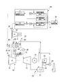
- the fuel preheater 49 for heating the fuel F is installed at a position adjacent to the radiator 32 of the cooler 31.
- the fuel F heated by the fuel preheater (first fuel preheater) 49 and the steam generated by the exhaust heat recovery boiler 21 or the heated water are further subjected to heat exchange, so that the fuel F A fuel preheater (second fuel preheater) 25 for further overheating is provided.
- the fuel F is heated using the heat of the air blown from the fan 33 of the cooler 31 and heated by heat exchange with the compressed air, and is generated in the exhaust heat recovery boiler 21.
- the fuel F is further heated using the heat of steam or heated water. Therefore, the power generation efficiency of the gas turbine can be further improved.
- the heat exchanger of the cooler 31 is the radiator 32, and the medium amount adjuster of the cooler 31 is the fan 33.
- a boiler water preheater 27 that exchanges heat of the boiler water supplied to the exhaust heat recovery boiler 21 with compressed air is used.
- a water amount adjustment valve (water amount adjuster) 28 for adjusting the flow rate of boiler water supplied to the boiler water preheater 27 is used as the amount adjuster.
- a water amount adjustment valve control system 61a that outputs an opening degree command to the water amount adjustment valve is provided instead of the fan control system 61.
- the boiler water supplied to the exhaust heat recovery boiler 21 is heat-exchanged with the compressed air, so that the compressed air can be cooled and the boiler water can be preheated.
- the differential pressure gauge 46 is provided, and the flow rate of the cooling air supplied to the combustion cylinder 13 of the combustor 12 is controlled based on the differential pressure ⁇ P detected by the differential pressure gauge 46.
- a flow meter for detecting the flow rate of the cooling air supplied to the combustor 12 is used in any of the lines that send the compressed air extracted from the air compressor 11 to the combustion cylinder 13 of the combustor 12.
- the flow rate of the cooling air supplied to the combustion cylinder 13 of the combustor 12 may be controlled based on the flow rate detected by the flow meter.
- the differential pressure target value setting unit 52 of the IGV control system 51 is a flow rate target value setting unit.
- the flow rate target setting unit uses a flow rate target value setting function that indicates the relationship between the flow rate target value, the gas turbine output P, and the temperature T of the pressurized cooling air detected by the thermometer 45, and A flow rate target value corresponding to the output P and the temperature T of the pressurized cooling air is determined. Further, the subtractor 53 of the IGV control system 51 obtains a deviation between the flow rate target value and the flow rate detected by the flow meter.
- the value corresponding to the flow rate of air supplied to the combustion cylinder 13 of the combustor 12 may be the flow rate of cooling air, or is correlated with the flow rate of air, for example, a difference. It may be a pressure ⁇ P or the like.
- the flow rate of the cooling air may be a volume flow rate or a mass flow rate.
- the differential pressure gauge 46 is installed to detect the differential pressure ⁇ P between the discharge pressure of the air compressor 11 and the inlet pressure of the pressurized cooling air to the combustor 12, but the air compressor 11 and the inlet pressure of the pressurized cooling air to the combustor 12 may be detected individually, and the pressure difference may be calculated by the control device 50 or 50a to obtain the differential pressure ⁇ P.
- the value of the power detected by a power meter or the like that detects the generated power of the generator 19 connected to the gas turbine 10 is used as the gas turbine output equivalent value.
- the gas turbine output equivalent value may be any parameter value that has a correlation with the gas turbine output P.
- the value of the fuel flow rate supplied to the gas turbine 10 The temperature of the combustion gas inlet of the turbine 10 assumed from the operating conditions 10 or a value obtained by making this temperature dimensionless may be used.
- thermometer 45 is provided in the pressurized cooling air line 43, but the thermometer 45 may be provided in the cooling air line 42 between the coolers 26 and 31 and the cooling air compressor 34. .
- the IGV 35 is used as the cooling air regulator.
- any device may be used as long as the flow rate of the cooling air supplied to the high temperature portion of the gas turbine 10 can be adjusted.
- the cooling air compressor 34 is provided with the IGV 35 as a cooling air regulator. This cooling air regulator may be provided on the downstream side even if provided on the upstream side of the cooling air compressor 34. It may be provided.
- the cooling air is supplied to the combustion cylinder 13 of the combustor 12, but the cooling air can be supplied to any place in the gas turbine 10 as long as it is in a high temperature portion that contacts the combustion gas.
- the cooling air may be supplied to the moving blades or stationary blades of the turbine 15.
- the temperature of the high temperature portion of the gas turbine can be suppressed to a predetermined value or less, and the power generation efficiency of the gas turbine can be improved.
Landscapes
- Engineering & Computer Science (AREA)
- Chemical & Material Sciences (AREA)
- Combustion & Propulsion (AREA)
- Mechanical Engineering (AREA)
- General Engineering & Computer Science (AREA)
- Physics & Mathematics (AREA)
- Fluid Mechanics (AREA)
- Control Of Turbines (AREA)
- Control Of Positive-Displacement Air Blowers (AREA)
Description
本願は、2012年9月27日に日本に出願された特願2012-215127号について優先権を主張し、その内容をここに援用する。
次に、ガスタービン設備に関する上記実施形態の第一変形例について、図6に基づいて説明する。
次に、ガスタービン設備の上記実施形態の第二変形例について、図7を基づいて説明する。
上記実施形態では、差圧計46を設け、この差圧計46で検知された差圧ΔPに基づいて、燃焼器12の燃焼筒13に供給する冷却空気の流量を制御している。しかしながら、この差圧計46の替りに、燃焼器12に供給する冷却空気の流量を検知する流量計を、空気圧縮機11から抽気した圧縮空気を燃焼器12の燃焼筒13に送るライン中のいずれかの位置に設け、この流量計で検知された流量に基づいて、燃焼器12の燃焼筒13に供給する冷却空気の流量を制御するようにしてもよい。この場合、IGV制御系51の差圧目標値設定部52は、流量目標値設定部となる。そして、この流量目標設定部は、流量目標値と、ガスタービン出力Pと、温度計45で検知される加圧冷却空気の温度Tとの関係を示す流量目標値設定関数を用いて、ガスタービン出力Pと加圧冷却空気の温度Tとに応じた流量目標値を定めことになる。さらに、IGV制御系51の減算器53は、この流量目標値と流量計で検知された流量との偏差を求めることになる。
また、上記実施形態では、空気圧縮機11の吐出圧と加圧冷却空気の燃焼器12への入口圧との差圧ΔPを検知するために差圧計46を設置しているが、空気圧縮機11の吐出圧と加圧冷却空気の燃焼器12への入口圧とをそれぞれ個別に設けた圧力計で検知し、制御装置50又は50aでその圧力差を演算して差圧ΔPとしてもよい。
11:空気圧縮機
12:燃焼器
13:燃焼筒
15:タービン
19:発電機
20:排熱回収装置
21:排熱回収ボイラー
25:燃料予熱器(第二燃料予熱器)
27:ボイラー水予熱器
28:水量調節弁
30:ガスタービン冷却系統
26,31:冷却器
32:ラジエター
33:ファン
34:冷却空気圧縮機
45:温度計
46:差圧計
49:燃料予熱器(第一燃料予熱器)
50:制御装置
51:IGV制御系
52:差圧目標値設定部
55:先行駆動量設定部
57:IGV駆動指令出力部
61:ファン制御系
62:温度目標値設定部
65:ファン駆動指令出力部
70:上位制御装置
Claims (16)
- ガスタービンの空気圧縮機から抽気した圧縮空気を冷却して冷却空気にする冷却器と、前記冷却空気をガスタービン中で燃焼ガスに接する高温部に供給する冷却空気圧縮機と、を備えているガスタービン冷却系統の制御方法において、
前記高温部に供給する前記冷却空気の流量相当値についての目標値と前記冷却空気の温度との関係を定めた目標値設定関数を用いて、検出された前記冷却空気の温度に応じた目標値を定める目標値設定工程と、
前記冷却空気の流量を調節する冷却空気量調節器の補正駆動量として、前記目標値に対する、検出された前記冷却空気の前記流量相当値の偏差が小さくなる補正駆動量を求める補正駆動量算出工程と、
前記補正駆動量に応じた駆動指令を前記冷却空気量調節器に出力する駆動指令出力工程と、
を実行するガスタービン冷却系統の制御方法。 - 請求項1に記載のガスタービン冷却系統の制御方法において、
前記目標値設定関数は、前記目標値と前記冷却空気の温度とガスタービン出力相当値との関係を定めており、前記目標値設定工程では、前記目標値設定関数を用いて、検出された前記冷却空気の温度と外部から得られた前記ガスタービン出力相当値とに応じた目標値を定める、
ガスタービン冷却系統の制御方法。 - 請求項1又は2に記載のガスタービン冷却系統の制御方法において、
前記冷却空気の温度と前記冷却空気量調節器の駆動量との関係を示す駆動量設定関数を用いて、検出された前記冷却空気の温度に応じた先行駆動量を定める先行駆動量設定工程を実行し、
前記駆動指令出力工程では、前記先行駆動量設定工程で定めた前記先行駆動量に前記補正駆動量に加えた駆動量に応じた駆動指令を出力する、
ガスタービン冷却系統の制御方法。 - 請求項3に記載のガスタービン冷却系統の制御方法において、
前記駆動量設定関数は、前記冷却空気の温度と、ガスタービン出力相当値と、前記冷却空気量調節器の駆動量との関係を定めており、前記先行駆動量設定工程では、前記駆動量設定関数を用いて、検出された前記冷却空気の温度と外部から得られた前記ガスタービン出力相当値とに応じた前記先行駆動量を定める、
ガスタービン冷却系統の制御方法。 - ガスタービンの空気圧縮機から抽気した圧縮空気を冷却して冷却空気にする冷却器と、前記冷却空気をガスタービン中で燃焼ガスに接する高温部に供給する冷却空気圧縮機と、を備えているガスタービン冷却系統の制御装置において、
前記冷却空気の流量相当値についての目標値と前記冷却空気の温度との関係を定めた目標値設定関数を用いて、検出された前記冷却空気の温度に応じた目標値を定める目標値設定部と、
前記冷却空気の流量を調節する冷却空気量調節器の補正駆動量として、前記目標値に対する、検出された前記冷却空気の前記流量相当値の偏差が小さくなる補正駆動量を求める補正駆動量算出部と、
前記補正駆動量に応じた駆動指令を前記冷却空気量調節器に出力する駆動指令出力部と、
を有するガスタービン冷却系統の制御装置。 - 請求項5に記載のガスタービン冷却系統の制御装置において、
前記目標値設定関数は、前記目標値と前記冷却空気の温度とガスタービン出力相当値との関係を定めており、前記目標値設定部は、前記目標値設定関数を用いて、検出された前記冷却空気の温度と外部から得られた前記ガスタービン出力相当値とに応じた目標値を定める、
ガスタービン冷却系統の制御装置。 - 請求項5又は6に記載のガスタービン冷却系統の制御装置において、
前記目標値設定関数は、前記冷却空気の温度が高くなるに連れて前記目標値が大きくなる関係を示す関数である、
ガスタービン冷却系統の制御装置。 - 請求項5から7のいずれか一項に記載のガスタービン冷却系統の制御装置において、
前記冷却空気の温度と前記冷却空気量調節器の駆動量との関係を示す駆動量設定関数を用いて、検出された前記冷却空気の温度に応じた先行駆動量を定める先行駆動量設定部を有し、
前記駆動指令出力部は、前記先行駆動量設定部が定めた前記先行駆動量に前記補正駆動量を加えた駆動量に応じた駆動指令を出力する、
ガスタービン冷却系統の制御装置。 - 請求項8に記載のガスタービン冷却系統の制御装置において、
前記駆動量設定関数は、前記冷却空気の温度と、ガスタービン出力相当値と、前記冷却空気量調節器の駆動量との関係を定めており、前記先行駆動量設定部は、該駆動量設定関数を用いて、検出された前記冷却空気の温度と外部から得られた前記ガスタービン出力相当値とに応じた先行駆動量を定める、
ガスタービン冷却系統の制御装置。 - 請求項5から9のいずれか一項に記載の制御装置と、
前記高温部に供給する前記冷却空気の温度を検出する温度計、前記冷却空気の前記流量相当値を検出する流量相当値計、前記冷却器、前記冷却空気圧縮機、及び前記冷却空気量調節器を備えている前記ガスタービン冷却系統と、
前記ガスタービンと、
を備えているガスタービン設備。 - 請求項10に記載のガスタービン設備において、
前記冷却器は、前記空気圧縮機からの圧縮空気と冷却媒体とを熱交換させる熱交換器と、前記冷却媒体の流量を調節する媒体量調節器と、を有し、
前記制御装置は、前記高温部に供給される前記冷却空気の温度が、前記冷却空気の温度の目標値である温度目標値になるよう、前記媒体量調節器に対して駆動指令を出力する駆動指令出力部を有する、
ガスタービン設備。 - 請求項11に記載のガスタービン設備において、
前記制御装置は、前記高温部に供給される前記冷却空気の温度の目標値である温度目標値とガスタービン出力相当値との関係を示す温度目標値設定関数を用いて、外部から得られた前記ガスタービン出力相当値に応じた前記温度目標値を定める温度目標値設定部を有する、
ガスタービン設備。 - 請求項11又は12に記載のガスタービン設備において、
前記冷却器の前記熱交換器は、空気を前記冷却媒体として前記圧縮空気と熱交換させるラジエターであり、前記冷却器の前記媒体量調節器は、前記ラジエターに送る前記空気の流量を調節できるファンである、
ガスタービン設備。 - 請求項13に記載のガスタービン設備において、
前記ファンから前記ラジエターに送られた空気と、前記ガスタービンの燃焼器に送る燃料とを熱交換させて、該燃料を加熱する燃料予熱器を備えている、
ガスタービン設備。 - 請求項13に記載のガスタービン設備において、
前記ガスタービンから排気された燃焼ガスとの熱交換で蒸気を発生させる排熱回収ボイラーと、
前記ファンから前記ラジエターに送られた空気と、前記ガスタービンの燃焼器に送る燃料とを熱交換させて、該燃料を加熱する第一燃料予熱器と、
前記燃料と前記排熱回収ボイラーで発生した蒸気又は加熱された水とを熱交換させて該燃料を加熱する第二燃料予熱器と、
を備えているガスタービン設備。 - 請求項11又は12に記載のガスタービン設備において、
前記ガスタービンから排気された燃焼ガスとの熱交換で蒸気を発生させる排熱回収ボイラーを備え、
前記冷却器の前記熱交換器は、前記排熱回収ボイラーに送る水を前記冷却媒体として前記圧縮空気と熱交換させるボイラー水予熱器であり、前記冷却器の前記媒体量調節器は、前記ボイラー水予熱器に送る前記水の流量を調節する水量調節器である、
ガスタービン設備。
Priority Applications (3)
| Application Number | Priority Date | Filing Date | Title |
|---|---|---|---|
| KR1020157002353A KR101576429B1 (ko) | 2012-09-27 | 2013-02-25 | 가스 터빈 냉각 계통의 제어 방법, 이 방법을 실행하는 제어 장치, 이것을 구비하고 있는 가스 터빈 설비 |
| CN201380038403.9A CN104520555B (zh) | 2012-09-27 | 2013-02-25 | 燃气涡轮冷却系统的控制方法、执行该方法的控制装置及具备该控制装置的燃气涡轮设备 |
| DE112013004755.1T DE112013004755B4 (de) | 2012-09-27 | 2013-02-25 | Verfahren zur Steuerung eines Kühlsystems einer Gasturbine, Steuervorrichtung zur Durchführung desselben und Gasturbinenanlage mit der Steuervorrichtung |
Applications Claiming Priority (2)
| Application Number | Priority Date | Filing Date | Title |
|---|---|---|---|
| JP2012-215127 | 2012-09-27 | ||
| JP2012215127A JP5787857B2 (ja) | 2012-09-27 | 2012-09-27 | ガスタービン冷却系統の制御方法、この方法を実行する制御装置、これを備えているガスタービン設備 |
Publications (1)
| Publication Number | Publication Date |
|---|---|
| WO2014050163A1 true WO2014050163A1 (ja) | 2014-04-03 |
Family
ID=50337526
Family Applications (1)
| Application Number | Title | Priority Date | Filing Date |
|---|---|---|---|
| PCT/JP2013/054727 Ceased WO2014050163A1 (ja) | 2012-09-27 | 2013-02-25 | ガスタービン冷却系統の制御方法、この方法を実行する制御装置、これを備えているガスタービン設備 |
Country Status (6)
| Country | Link |
|---|---|
| US (1) | US10465563B2 (ja) |
| JP (1) | JP5787857B2 (ja) |
| KR (1) | KR101576429B1 (ja) |
| CN (1) | CN104520555B (ja) |
| DE (1) | DE112013004755B4 (ja) |
| WO (1) | WO2014050163A1 (ja) |
Families Citing this family (15)
| Publication number | Priority date | Publication date | Assignee | Title |
|---|---|---|---|---|
| US20120198846A1 (en) * | 2011-02-04 | 2012-08-09 | Sieben Amy L | Air cooling system and method for a heat recovery steam generator inlet |
| EP2565442A1 (en) * | 2011-09-05 | 2013-03-06 | Siemens Aktiengesellschaft | System and method for operating a wind turbine using adaptive reference variables |
| JP6039056B2 (ja) | 2012-04-02 | 2016-12-07 | パワーフェイズ・エルエルシー | ガスタービンエンジン用の圧縮空気注入システム方法および装置 |
| WO2014066276A2 (en) | 2012-10-26 | 2014-05-01 | Kraft Robert J | Gas turbine energy supplementing systems and heating systems, and methods of making and using the same |
| WO2015064428A1 (ja) * | 2013-10-29 | 2015-05-07 | 三菱日立パワーシステムズ株式会社 | 温度制御装置、ガスタービン、温度制御方法およびプログラム |
| CN105157063B (zh) * | 2015-09-18 | 2018-04-13 | 中国航空工业集团公司沈阳发动机设计研究所 | 一种流量分配可调的火焰筒 |
| JP6700776B2 (ja) | 2015-12-24 | 2020-05-27 | 三菱日立パワーシステムズ株式会社 | ガスタービン冷却系統、これを備えるガスタービン設備、ガスタービン冷却系統の制御装置及び制御方法 |
| JP6587350B2 (ja) | 2016-01-22 | 2019-10-09 | 三菱日立パワーシステムズ株式会社 | ガスタービン冷却系統、これを備えるガスタービン設備、ガスタービン冷却系統の制御方法 |
| CN108884727B (zh) | 2016-03-30 | 2020-11-06 | 三菱重工业株式会社 | 成套设备及其运转方法 |
| JP6730116B2 (ja) * | 2016-07-08 | 2020-07-29 | 株式会社東芝 | プラント制御装置、プラント制御方法、および発電プラント |
| JP7129810B2 (ja) * | 2018-04-13 | 2022-09-02 | 三菱重工業株式会社 | 冷却空気調整弁の弁開度決定装置、ディスクキャビティ目標温度決定装置、およびディスクキャビティ温度制御装置 |
| JP7120893B2 (ja) * | 2018-11-20 | 2022-08-17 | 三菱重工業株式会社 | ガスタービン及びその抽気量調整方法 |
| CN109596371B (zh) * | 2018-12-10 | 2020-01-03 | 湘潭大学 | 一种涡轮叶片热障涂层的冷却工况加载设备 |
| CN109781446A (zh) * | 2019-01-11 | 2019-05-21 | 贵州永红航空机械有限责任公司 | 一种飞机制冷包升压式空气轴承涡轮冷却器性能试验装置 |
| CN120781725A (zh) * | 2025-06-10 | 2025-10-14 | 中国联合重型燃气轮机技术有限公司 | 燃气轮机气冷透平性能计算方法、装置、电子设备 |
Citations (5)
| Publication number | Priority date | Publication date | Assignee | Title |
|---|---|---|---|---|
| JPS6226329A (ja) * | 1985-07-29 | 1987-02-04 | Hitachi Ltd | ガスタービンのホットパーツ冷却方法 |
| WO2001034956A1 (fr) * | 1999-11-10 | 2001-05-17 | Hitachi, Ltd. | Materiel de turbine a gaz et procede de refroidissement de celle-ci |
| JP2007016791A (ja) * | 2006-09-13 | 2007-01-25 | Hitachi Ltd | コンバインド発電プラントおよびクローズド空気冷却ガスタービンシステム |
| JP2008291829A (ja) * | 2007-04-27 | 2008-12-04 | Hitachi Ltd | ガスタービン設備 |
| WO2010001655A1 (ja) * | 2008-06-30 | 2010-01-07 | 三菱重工業株式会社 | ガスタービン及びガスタービンの運転方法 |
Family Cites Families (14)
| Publication number | Priority date | Publication date | Assignee | Title |
|---|---|---|---|---|
| JPH07189740A (ja) | 1993-12-27 | 1995-07-28 | Hitachi Ltd | ガスタービン冷却系統 |
| JP3150567B2 (ja) * | 1995-04-14 | 2001-03-26 | 三菱重工業株式会社 | ガスタービン燃料加熱装置 |
| US5826430A (en) * | 1996-04-23 | 1998-10-27 | Westinghouse Electric Corporation | Fuel heating system used in conjunction with steam cooled combustors and transitions |
| JPH1150809A (ja) * | 1997-08-01 | 1999-02-23 | Mitsubishi Heavy Ind Ltd | 回転体の伸び量調整装置 |
| JPH1193694A (ja) | 1997-09-18 | 1999-04-06 | Toshiba Corp | ガスタービンプラント |
| JP3117424B2 (ja) | 1997-10-21 | 2000-12-11 | 三菱重工業株式会社 | ガスタービンコンバインドプラント |
| JP3035289B1 (ja) | 1999-03-11 | 2000-04-24 | 三菱重工業株式会社 | ハイブリッド燃焼器 |
| US6739119B2 (en) | 2001-12-31 | 2004-05-25 | Donald C. Erickson | Combustion engine improvement |
| JP4119908B2 (ja) | 2005-09-14 | 2008-07-16 | 三菱重工業株式会社 | ガスタービンの燃焼制御装置 |
| JP2008082247A (ja) | 2006-09-27 | 2008-04-10 | Mitsubishi Heavy Ind Ltd | ガスタービン |
| US8220268B2 (en) * | 2007-11-28 | 2012-07-17 | Caterpillar Inc. | Turbine engine having fuel-cooled air intercooling |
| JP5117431B2 (ja) | 2009-03-09 | 2013-01-16 | 株式会社日立製作所 | 二酸化炭素回収型ガスタービンプラント |
| JP5653705B2 (ja) | 2010-09-30 | 2015-01-14 | 三菱重工業株式会社 | 回収式空気冷却ガスタービン燃焼器冷却構造 |
| ITTO20100824A1 (it) * | 2010-10-06 | 2012-04-07 | Ansaldo Energia Spa | Metodo di controllo per raffreddare uno stadio di turbina in una turbina a gas |
-
2012
- 2012-09-27 JP JP2012215127A patent/JP5787857B2/ja active Active
-
2013
- 2013-02-22 US US13/774,409 patent/US10465563B2/en active Active
- 2013-02-25 WO PCT/JP2013/054727 patent/WO2014050163A1/ja not_active Ceased
- 2013-02-25 KR KR1020157002353A patent/KR101576429B1/ko active Active
- 2013-02-25 CN CN201380038403.9A patent/CN104520555B/zh active Active
- 2013-02-25 DE DE112013004755.1T patent/DE112013004755B4/de active Active
Patent Citations (5)
| Publication number | Priority date | Publication date | Assignee | Title |
|---|---|---|---|---|
| JPS6226329A (ja) * | 1985-07-29 | 1987-02-04 | Hitachi Ltd | ガスタービンのホットパーツ冷却方法 |
| WO2001034956A1 (fr) * | 1999-11-10 | 2001-05-17 | Hitachi, Ltd. | Materiel de turbine a gaz et procede de refroidissement de celle-ci |
| JP2007016791A (ja) * | 2006-09-13 | 2007-01-25 | Hitachi Ltd | コンバインド発電プラントおよびクローズド空気冷却ガスタービンシステム |
| JP2008291829A (ja) * | 2007-04-27 | 2008-12-04 | Hitachi Ltd | ガスタービン設備 |
| WO2010001655A1 (ja) * | 2008-06-30 | 2010-01-07 | 三菱重工業株式会社 | ガスタービン及びガスタービンの運転方法 |
Also Published As
| Publication number | Publication date |
|---|---|
| JP2014070510A (ja) | 2014-04-21 |
| DE112013004755B4 (de) | 2020-08-13 |
| US10465563B2 (en) | 2019-11-05 |
| DE112013004755T5 (de) | 2015-09-03 |
| KR101576429B1 (ko) | 2015-12-09 |
| JP5787857B2 (ja) | 2015-09-30 |
| KR20150036248A (ko) | 2015-04-07 |
| CN104520555A (zh) | 2015-04-15 |
| CN104520555B (zh) | 2016-03-30 |
| US20140083108A1 (en) | 2014-03-27 |
Similar Documents
| Publication | Publication Date | Title |
|---|---|---|
| JP5787857B2 (ja) | ガスタービン冷却系統の制御方法、この方法を実行する制御装置、これを備えているガスタービン設備 | |
| JP2014070510A5 (ja) | ||
| JP6189271B2 (ja) | ガスタービン、ガスタービンの制御装置及びガスタービンの運転方法 | |
| CN105089721B (zh) | 热能回收装置和控制方法 | |
| CN108474300B (zh) | 燃气轮机冷却系统、具备其的燃气轮机设备、燃气轮机冷却系统的控制装置以及控制方法 | |
| JP6578136B2 (ja) | コンバインドサイクルプラント、その制御装置及び起動方法 | |
| JP6264128B2 (ja) | コンバインドサイクルプラント、その制御方法、及びその制御装置 | |
| JP4885199B2 (ja) | ガスタービン運転制御装置及び方法 | |
| EP2623751B1 (en) | Method and apparatus to control part-load performance of a turbine | |
| JP2009057950A (ja) | ガスタービンの吸気加熱制御装置 | |
| US10883378B2 (en) | Combined cycle plant and method for controlling operation of combine cycle plant | |
| JP4948348B2 (ja) | コンバインドサイクル発電プラント | |
| JP2008128086A (ja) | ガスタービンの吸気加熱制御装置 | |
| WO2014033837A1 (ja) | 排熱回収ボイラ、排熱回収ボイラの制御方法、及びこれを用いたコンバインドサイクル発電プラント | |
| WO2012176256A1 (ja) | 閉サイクルガスタービン及びその運転方法 | |
| CN203925754U (zh) | 具有到hrsg和风扇的气流旁路的增压联合循环系统 | |
| JP5675527B2 (ja) | ガスタービン制御装置及びガスタービン制御方法 | |
| JP6590650B2 (ja) | コンバインドサイクルプラント及びその制御装置、運転方法 | |
| JP7253403B2 (ja) | 発電システム | |
| EP3936703B1 (en) | Power plant and method for operating said power plant | |
| JPS58107805A (ja) | コンバインドサイクル発電用タ−ビンの制御方法 |
Legal Events
| Date | Code | Title | Description |
|---|---|---|---|
| WWE | Wipo information: entry into national phase |
Ref document number: 201380038403.9 Country of ref document: CN |
|
| 121 | Ep: the epo has been informed by wipo that ep was designated in this application |
Ref document number: 13842012 Country of ref document: EP Kind code of ref document: A1 |
|
| ENP | Entry into the national phase |
Ref document number: 20157002353 Country of ref document: KR Kind code of ref document: A |
|
| WWE | Wipo information: entry into national phase |
Ref document number: 1120130047551 Country of ref document: DE Ref document number: 112013004755 Country of ref document: DE |
|
| 122 | Ep: pct application non-entry in european phase |
Ref document number: 13842012 Country of ref document: EP Kind code of ref document: A1 |