WO2014049797A1 - プレフィルドシリンジ用外筒、プレフィルドシリンジ用穿刺具、プレフィルドシリンジおよびプレフィルドシリンジ用外筒包装体 - Google Patents
プレフィルドシリンジ用外筒、プレフィルドシリンジ用穿刺具、プレフィルドシリンジおよびプレフィルドシリンジ用外筒包装体 Download PDFInfo
- Publication number
- WO2014049797A1 WO2014049797A1 PCT/JP2012/074988 JP2012074988W WO2014049797A1 WO 2014049797 A1 WO2014049797 A1 WO 2014049797A1 JP 2012074988 W JP2012074988 W JP 2012074988W WO 2014049797 A1 WO2014049797 A1 WO 2014049797A1
- Authority
- WO
- WIPO (PCT)
- Prior art keywords
- outer cylinder
- prefilled syringe
- puncture
- sealing member
- puncture member
- Prior art date
- Legal status (The legal status is an assumption and is not a legal conclusion. Google has not performed a legal analysis and makes no representation as to the accuracy of the status listed.)
- Ceased
Links
Images













Classifications
-
- B—PERFORMING OPERATIONS; TRANSPORTING
- B65—CONVEYING; PACKING; STORING; HANDLING THIN OR FILAMENTARY MATERIAL
- B65D—CONTAINERS FOR STORAGE OR TRANSPORT OF ARTICLES OR MATERIALS, e.g. BAGS, BARRELS, BOTTLES, BOXES, CANS, CARTONS, CRATES, DRUMS, JARS, TANKS, HOPPERS, FORWARDING CONTAINERS; ACCESSORIES, CLOSURES, OR FITTINGS THEREFOR; PACKAGING ELEMENTS; PACKAGES
- B65D25/00—Details of other kinds or types of rigid or semi-rigid containers
- B65D25/02—Internal fittings
- B65D25/10—Devices to locate articles in containers
- B65D25/108—Devices, e.g. plates, presenting apertures through which the articles project
-
- A—HUMAN NECESSITIES
- A61—MEDICAL OR VETERINARY SCIENCE; HYGIENE
- A61M—DEVICES FOR INTRODUCING MEDIA INTO, OR ONTO, THE BODY; DEVICES FOR TRANSDUCING BODY MEDIA OR FOR TAKING MEDIA FROM THE BODY; DEVICES FOR PRODUCING OR ENDING SLEEP OR STUPOR
- A61M5/00—Devices for bringing media into the body in a subcutaneous, intra-vascular or intramuscular way; Accessories therefor, e.g. filling or cleaning devices, arm-rests
- A61M5/002—Packages specially adapted therefor, e.g. for syringes or needles, kits for diabetics
-
- A—HUMAN NECESSITIES
- A61—MEDICAL OR VETERINARY SCIENCE; HYGIENE
- A61M—DEVICES FOR INTRODUCING MEDIA INTO, OR ONTO, THE BODY; DEVICES FOR TRANSDUCING BODY MEDIA OR FOR TAKING MEDIA FROM THE BODY; DEVICES FOR PRODUCING OR ENDING SLEEP OR STUPOR
- A61M5/00—Devices for bringing media into the body in a subcutaneous, intra-vascular or intramuscular way; Accessories therefor, e.g. filling or cleaning devices, arm-rests
- A61M5/178—Syringes
- A61M5/28—Syringe ampoules or carpules, i.e. ampoules or carpules provided with a needle
- A61M5/285—Syringe ampoules or carpules, i.e. ampoules or carpules provided with a needle with sealing means to be broken or opened
- A61M5/288—Syringe ampoules or carpules, i.e. ampoules or carpules provided with a needle with sealing means to be broken or opened by piercing without internal pressure increase
-
- A—HUMAN NECESSITIES
- A61—MEDICAL OR VETERINARY SCIENCE; HYGIENE
- A61M—DEVICES FOR INTRODUCING MEDIA INTO, OR ONTO, THE BODY; DEVICES FOR TRANSDUCING BODY MEDIA OR FOR TAKING MEDIA FROM THE BODY; DEVICES FOR PRODUCING OR ENDING SLEEP OR STUPOR
- A61M5/00—Devices for bringing media into the body in a subcutaneous, intra-vascular or intramuscular way; Accessories therefor, e.g. filling or cleaning devices, arm-rests
- A61M5/178—Syringes
- A61M5/31—Details
- A61M5/32—Needles; Details of needles pertaining to their connection with syringe or hub; Accessories for bringing the needle into, or holding the needle on, the body; Devices for protection of needles
- A61M5/3202—Devices for protection of the needle before use, e.g. caps
-
- A—HUMAN NECESSITIES
- A61—MEDICAL OR VETERINARY SCIENCE; HYGIENE
- A61M—DEVICES FOR INTRODUCING MEDIA INTO, OR ONTO, THE BODY; DEVICES FOR TRANSDUCING BODY MEDIA OR FOR TAKING MEDIA FROM THE BODY; DEVICES FOR PRODUCING OR ENDING SLEEP OR STUPOR
- A61M5/00—Devices for bringing media into the body in a subcutaneous, intra-vascular or intramuscular way; Accessories therefor, e.g. filling or cleaning devices, arm-rests
- A61M5/178—Syringes
- A61M5/31—Details
- A61M5/32—Needles; Details of needles pertaining to their connection with syringe or hub; Accessories for bringing the needle into, or holding the needle on, the body; Devices for protection of needles
- A61M5/34—Constructions for connecting the needle, e.g. to syringe nozzle or needle hub
- A61M5/347—Constructions for connecting the needle, e.g. to syringe nozzle or needle hub rotatable, e.g. bayonet or screw
-
- A—HUMAN NECESSITIES
- A61—MEDICAL OR VETERINARY SCIENCE; HYGIENE
- A61M—DEVICES FOR INTRODUCING MEDIA INTO, OR ONTO, THE BODY; DEVICES FOR TRANSDUCING BODY MEDIA OR FOR TAKING MEDIA FROM THE BODY; DEVICES FOR PRODUCING OR ENDING SLEEP OR STUPOR
- A61M5/00—Devices for bringing media into the body in a subcutaneous, intra-vascular or intramuscular way; Accessories therefor, e.g. filling or cleaning devices, arm-rests
- A61M5/178—Syringes
- A61M5/31—Details
- A61M5/32—Needles; Details of needles pertaining to their connection with syringe or hub; Accessories for bringing the needle into, or holding the needle on, the body; Devices for protection of needles
- A61M5/34—Constructions for connecting the needle, e.g. to syringe nozzle or needle hub
- A61M5/348—Constructions for connecting the needle, e.g. to syringe nozzle or needle hub snap lock, i.e. upon axial displacement of needle assembly
-
- A—HUMAN NECESSITIES
- A61—MEDICAL OR VETERINARY SCIENCE; HYGIENE
- A61M—DEVICES FOR INTRODUCING MEDIA INTO, OR ONTO, THE BODY; DEVICES FOR TRANSDUCING BODY MEDIA OR FOR TAKING MEDIA FROM THE BODY; DEVICES FOR PRODUCING OR ENDING SLEEP OR STUPOR
- A61M5/00—Devices for bringing media into the body in a subcutaneous, intra-vascular or intramuscular way; Accessories therefor, e.g. filling or cleaning devices, arm-rests
- A61M5/178—Syringes
- A61M5/31—Details
- A61M2005/3117—Means preventing contamination of the medicament compartment of a syringe
- A61M2005/3118—Means preventing contamination of the medicament compartment of a syringe via the distal end of a syringe, i.e. syringe end for mounting a needle cannula
- A61M2005/312—Means preventing contamination of the medicament compartment of a syringe via the distal end of a syringe, i.e. syringe end for mounting a needle cannula comprising sealing means, e.g. severable caps, to be removed prior to injection by, e.g. tearing or twisting
-
- A—HUMAN NECESSITIES
- A61—MEDICAL OR VETERINARY SCIENCE; HYGIENE
- A61M—DEVICES FOR INTRODUCING MEDIA INTO, OR ONTO, THE BODY; DEVICES FOR TRANSDUCING BODY MEDIA OR FOR TAKING MEDIA FROM THE BODY; DEVICES FOR PRODUCING OR ENDING SLEEP OR STUPOR
- A61M5/00—Devices for bringing media into the body in a subcutaneous, intra-vascular or intramuscular way; Accessories therefor, e.g. filling or cleaning devices, arm-rests
- A61M5/008—Racks for supporting syringes or needles
-
- A—HUMAN NECESSITIES
- A61—MEDICAL OR VETERINARY SCIENCE; HYGIENE
- A61M—DEVICES FOR INTRODUCING MEDIA INTO, OR ONTO, THE BODY; DEVICES FOR TRANSDUCING BODY MEDIA OR FOR TAKING MEDIA FROM THE BODY; DEVICES FOR PRODUCING OR ENDING SLEEP OR STUPOR
- A61M5/00—Devices for bringing media into the body in a subcutaneous, intra-vascular or intramuscular way; Accessories therefor, e.g. filling or cleaning devices, arm-rests
- A61M5/178—Syringes
- A61M5/31—Details
- A61M5/315—Pistons; Piston-rods; Guiding, blocking or restricting the movement of the rod or piston; Appliances on the rod for facilitating dosing ; Dosing mechanisms
- A61M5/31511—Piston or piston-rod constructions, e.g. connection of piston with piston-rod
- A61M5/31515—Connection of piston with piston rod
Definitions
- the present invention relates to a prefilled syringe outer cylinder, a prefilled syringe puncture device, a prefilled syringe, and a prefilled syringe outer cylinder package.
- the prefilled syringe is provided in a state where it is filled with a medical liquid such as a drug solution or a drug solution.
- a medical liquid such as a drug solution or a drug solution.
- a prefilled syringe for example, there is a prefilled syringe whose tip is sealed with a cap to which a double-ended needle can be attached.
- a puncture member having a double-ended needle is attached at the time of use.
- Patent Document 1 Japanese Patent Publication No. 2010-540122: WO2009 / 043000.
- the assembly 10 of Patent Document 1 includes a tubular body 16, a first stopper 18, a second stopper 20, a flexible insert 22, and a rigid retainer 24.
- the flexible insert 22 is formed from a material that can be pierced by a medical needle or other piercing device. The surface of the flexible insert 22 that is pierced by a medical needle or other piercing device is exposed. Thus, if bacteria adhere to the surface by the time of use, there is a risk that the bacteria will be mixed into the assembly 10 by the inserted medical needle or other piercing device. And there exists a danger that the microbe mixed in the assembly 10 will be administered with the chemical
- the object of the present invention is to keep the surface of the sealing member that seals the tip of the syringe outer cylinder from being contaminated until use, and to use the syringe outer cylinder with a simple operation.
- a prefilled syringe outer cylinder, a prefilled syringe puncture tool, a prefilled syringe, and a prefilled syringe outer cylinder package that can be put into a possible state, in other words, a puncture member having a double-ended needle can be mounted. is there.
- a prefilled syringe outer cylinder to which a puncture member comprising a hollow needle having needle portions at both ends and a puncture member body mounted with the hollow needle can be mounted wherein the prefilled syringe outer cylinder has a tip having an opening
- the outer cylinder sealing member is formed between the puncture member mounting portion and the rupture operation portion, and the rupture operation portion protruding from the puncture member mounting portion.
- a breakable portion, and the breakable portion is By separating the breaking operation section, the puncture member prefilled syringe outer cylinder for the piercing member to the mounting portion is made can be mounted.
- the puncture member comprising: the hollow needle having the needle portions at both ends; and the puncture member main body having the hollow needle attached thereto and being attachable to the outer cylinder sealing member and having a puncture member side engagement portion; And a storage member that detachably stores the puncture member, and the storage member has the puncture member mounted on the outer cylinder sealing member, and the puncture member side engagement portion and the outer cylinder seal
- the outer cylinder holding member capable of holding the prefilled syringe outer cylinder, the plurality of prefilled syringe outer cylinders held by the outer cylinder holding member, and the upper surface opening of the container body are hermetically sealed and peelable
- the package body further includes a vent portion that is provided in the container body or the lid member and has an air-permeable portion that is impermeable to water vapor and has water vapor flow.
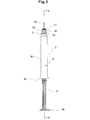
- FIG. 1 is a front view of a prefilled syringe and a puncture tool for a prefilled syringe according to the present invention.
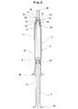
- FIG. 2 is a right side view of the prefilled syringe shown in FIG.
- FIG. 3 is an enlarged cross-sectional view taken along line AA in FIG.
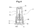
- FIG. 4 is an enlarged longitudinal sectional view of the prefilled syringe puncture device of the present invention.
- FIG. 5 is an enlarged cross-sectional view of the distal end portion of the prefilled syringe outer cylinder shown in FIG. 1.
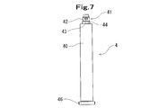
- FIG. 6 is a front view of the prefilled syringe outer cylinder and the outer cylinder used in the prefilled syringe of the present invention.
- FIG. 7 is a right side view of the outer cylinder shown in FIG.
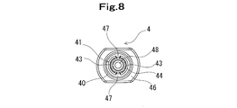
- FIG. 8 is an enlarged plan view of the outer cylinder shown in FIG.
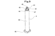
- FIG. 9 is a perspective view of the outer cylinder shown in FIG.
- FIG. 10 is a front view of the outer cylinder sealing member used for the prefilled syringe outer cylinder and the prefilled syringe of the present invention.
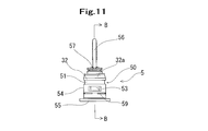
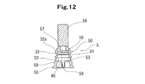
- FIG. 11 is a right side view of the outer cylinder sealing member shown in FIG. 12 is a cross-sectional view taken along line BB in FIG.
- FIG. 13 is an enlarged front view of a puncture member used in the prefilled syringe puncture device of the present invention.
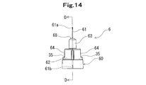
- FIG. 14 is a left side view of the puncture member shown in FIG.
- FIG. 15 is a cross-sectional view taken along the line CC of FIG. 16 is a cross-sectional view taken along the line DD of FIG. 17 is a perspective view of the puncture member shown in FIG.
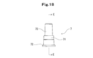
- FIG. 18 is an enlarged front view of a storage member used for the prefilled syringe puncture device of the present invention.
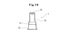
- 19 is a cross-sectional view taken along line EE in FIG.
- FIG. 20 is an enlarged front view of a plunger used in the prefilled syringe of the present invention.
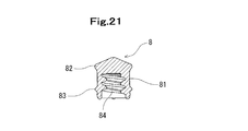
- FIG. 21 is a cross-sectional view of a gasket used in the prefilled syringe of the present invention.
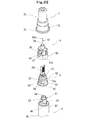
- FIG. 22 is an explanatory diagram for explaining constituent members used for the prefilled syringe and the puncture member shown in FIG.
- FIG. 23 is an explanatory diagram for explaining the operation of the prefilled syringe outer cylinder shown in FIG. 1.
- FIG. 24 is an explanatory diagram for explaining the action of the prefilled syringe outer cylinder shown in FIG. 1.
- FIG. 25 is an explanatory diagram for explaining the operation of the prefilled syringe outer cylinder and the puncture member shown in FIG. 1.
- FIG. 26 is an explanatory diagram for explaining the operation of the prefilled syringe outer cylinder and the puncture member shown in FIG. 1.
- FIG. 27 is an explanatory diagram for explaining a state in which the puncture member is attached to the prefilled syringe outer cylinder shown in FIG. 1.
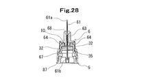
- FIG. 28 is an explanatory diagram for explaining how the outer cylinder sealing member and the puncture member of the prefilled syringe outer cylinder shown in FIG. 1 are mounted.
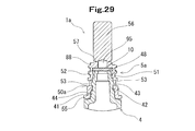
- FIG. 29 is an enlarged cross-sectional view of the distal end portion of the prefilled syringe outer cylinder of another embodiment of the present invention.
- 30 is an enlarged longitudinal sectional view of a puncture device used in the prefilled syringe shown in FIG.
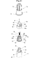
- FIG. 31 is an explanatory diagram for explaining constituent members of the prefilled syringe using the prefilled syringe outer cylinder shown in FIG. 29 and the puncture tool shown in FIG. 30.
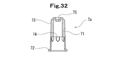
- 32 is a longitudinal sectional view of the storage member shown in FIG. FIG.
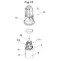
- FIG. 33 is an explanatory diagram for explaining the operation of the prefilled syringe using the prefilled syringe outer cylinder shown in FIG. 29 and the puncture device shown in FIG. 30.
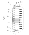
- FIG. 34 is a perspective view of the prefilled syringe outer cylinder package of the present invention.
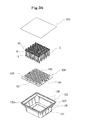
- FIG. 35 is an explanatory diagram for describing an internal configuration of the prefilled syringe outer cylinder package illustrated in FIG. 34.
- 36 is a front view of the prefilled syringe outer cylinder package shown in FIG. 34.
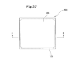
- FIG. FIG. 37 is a plan view of the prefilled syringe outer cylinder package shown in FIG.
- FIG. 38 is an enlarged sectional view taken along line FF in FIG.
- the prefilled syringe outer cylinder, the prefilled syringe puncture tool, the prefilled syringe, and the prefilled syringe outer cylinder package of the present invention will be described with reference to the embodiments shown in the drawings.
- the prefilled syringe outer cylinder 2 of the present invention can be mounted with a puncture member 6 including a hollow needle 61 having needle portions 61a and 61b at both ends and a puncture member body 60 to which the hollow needle 61 is mounted.
- the prefilled syringe outer cylinder 2 is a seal that seals the outer cylinder body 4 having a tip 41 having an opening 48 and the opening 48 of the tip 41 and allows the needle 61b of the hollow needle 61 to be pierced.
- the outer cylinder sealing member 5 that houses the member 10 and is attached to the distal end portion 41 of the outer cylinder main body 4 is provided.
- the outer cylinder sealing member 5 includes a puncture member mounting portion 50 to which the puncture member 6 can be mounted, and a restricting portion that restricts detachment and rotation of the outer cylinder sealing member 5 mounted on the outer cylinder main body 4.
- the outer cylinder sealing member 5 includes a breaking operation portion 56 protruding from the puncture member mounting portion 50, and a breakable portion 57 formed between the puncture member mounting portion 50 and the breaking operation portion 56, and the breakable portion
- the puncture member 6 can be attached to the puncture member attachment portion 50 by breaking 57 and separating the break operation portion 56.
- the sealing member 10 is covered with the breaking operation part, and the surface thereof is not exposed, so that the clean state is maintained until use. Moreover, in the state which does not isolate
- the puncture member 6 of this embodiment has a puncture member side engagement portion 35 provided in the puncture member main body 60, and the prefilled syringe outer cylinder 2 (including the outer cylinder sealing member 5) is associated with the puncture member side engagement.
- the outer cylinder sealing member side engaging part 32 which engages with the joint part 35 and regulates the detachment of the puncture member 6 from the outer cylinder sealing member 5 after engagement is provided.
- the outer cylinder sealing member 5 is engaged with the puncture member side engaging portion 35 by pushing the prefilled syringe outer cylinder 2 into the puncture member 6 from the outer cylinder sealing member 5 side, It has the outer cylinder sealing member side engaging part 32 which controls the detachment
- the puncture member 6 is mounted by pushing the outer cylinder sealing member 5 of the outer cylinder 2 from which the breaking operation portion 56 is separated into the outer cylinder. And easy.
- the outer cylinder sealing member 5 includes a breaking operation portion 56 that protrudes from the puncture member mounting portion 50, and a breakable portion 57 formed between the puncture member mounting portion 50 and the breaking operation portion 56.
- the puncture member 6 can be attached to the puncture member attachment portion 50 by breaking 57 and separating the break operation portion 56.
- the prefilled syringe 1 of this embodiment includes a prefilled syringe outer cylinder 2 and a gasket 8 which is housed in the outer cylinder 2 and can slide in a liquid-tight manner in the outer cylinder. And the medicine 11 accommodated in the space formed by the outer cylinder 2 and the gasket 8.
- the prefilled syringe outer cylinder 2 is formed on the outer cylinder main body 4 having a tip 41 having an opening 48 and the tip 41 of the outer cylinder main body 4. And a mounted outer cylinder sealing member 5.
- the outer cylinder main body 4 includes a main body portion 40, a distal end portion 41, and a flange 46.
- the main body 40 is substantially cylindrical and has a liquid storage space inside.
- the tip portion 41 protrudes from the shoulder portion of the main body portion 40 in the tip direction.
- the distal end portion 41 includes a distal end opening 48 for discharging a chemical solution or the like in the outer cylinder and cannot be connected to a medical device having a connection portion to a nozzle portion conforming to the ISO standard. That is, it is not a luer taper shape that the tip of a normal syringe has.
- the distal end portion 41 includes a diameter-expanded portion 44 formed at a boundary portion with the main-body portion 40, and a concave portion 47 (specifically, Two concavities facing each other) and near the tip of the intermediate portion 42 of the tip 41 (a portion having a smaller diameter than the enlarged diameter portion 44 and a diameter larger than the most distal portion) (in other words, near the central portion in the axial direction of the tip 41).
- the protruding portion 43 (specifically, two protruding portions facing each other) is provided.
- tip part 41 is equipped with the small diameter part at the front-end
- the protrusion part 43 is extended predetermined length in the circumferential direction.
- the two recesses 47 extend a predetermined length in the axial direction.
- the two protrusions 43 and the two recesses 47 are provided so as not to overlap in the axial direction.
- each recessed portion 47 and each protruding portion 43 are displaced by approximately 90 degrees with respect to the central axis of the tip end portion 41.
- tip part 41 of the outer cylinder main body 4 comprises the engaging part for outer cylinder sealing member detachment
- the flange 46 is an elliptical donut-shaped disk portion formed so as to protrude in the vertical direction from the entire rear end circumference of the outer cylinder body 4. As shown in FIGS. 8 and 9, the flange 46 includes two grip portions facing each other.
- the outer cylinder body 4 is a cylindrical body made of a transparent or translucent material, if necessary, made of a material having low oxygen permeability and water vapor permeability.
- Examples of the material for forming the outer cylinder body 4 include polypropylene, polyethylene, polystyrene, polyamide, polycarbonate, polyvinyl chloride, poly- (4-methylpentene-1), acrylic resin, acrylonitrile-butadiene-styrene copolymer, polyethylene.
- Various resins such as polyesters such as terephthalate and cyclic polyolefins may be mentioned. Among them, resins such as polypropylene and cyclic polyolefins are preferred because they are easy to mold and have heat resistance.
- the outer cylinder sealing member 5 includes a hollow main body 51 having a puncture member mounting portion 50 and an operation portion 56. And a seal member 10 accommodated in the main body 51. A closed space 95 is formed between the inner surface of the outer cylinder sealing member 5 and the upper surface of the seal member 10. The outer cylinder sealing member 5 is closed at the tip by the breaking operation portion 56.
- the puncture member mounting portion 50 includes a cylindrical small diameter portion provided at the distal end, a flange portion 55 provided at the proximal end, and a window portion 53 provided on the side portion (specifically, two window portions facing each other). ), A puncture member side engagement portion (annular rib) 32 provided on the outer surface on the distal end side from the window portion 53, and a rib 59 (plurality) formed on the distal end side from the flange portion 55 and on the proximal end side from the window portion 53. And a projecting portion 58 (specifically, two projecting portions facing each other) extending in the axial direction provided on the inner surface of the base end portion of the main body 51.
- the window 53 is for accommodating and engaging the protruding portion 43 of the outer cylinder main body 4, and extends a predetermined length in the circumferential direction. .
- the protrusion 43 of the outer cylinder main body 4 enters the window 53 of the outer cylinder sealing member 5 and engages to prevent the outer cylinder sealing member from being detached from the outer cylinder main body 4 and rotate. It also regulates. Therefore, in the prefilled syringe 1 of this embodiment, the outer cylinder sealing member 5 cannot be detached from the outer cylinder main body 4.
- the outer cylinder sealing member 5 When the outer cylinder sealing member 5 is mounted on the outer cylinder main body 4, the protrusion 58 provided on the inner surface of the base end portion of the outer cylinder sealing member 5 enters the concave portion 47 of the outer cylinder main body 4. And are engaged. For this reason, the outer cylinder sealing member 5 cannot rotate with respect to the outer cylinder main body 4. Therefore, by rotating the outer cylinder main body 4, the outer cylinder sealing member 5 follows and rotates. Therefore, the window portion 53 of the outer cylinder sealing member 5 constitutes an outer cylinder sealing member detachment restricting engagement portion on the cylindrical body side, and the projecting portion 58 is an outer cylinder sealing member rotation restriction on the cylindrical body side.
- the engagement part is constituted.
- the outer cylinder sealing member side engaging part 32 is provided in the outer surface of the front end side part of the puncture member mounting part 50.
- the outer cylinder sealing member side engaging portion 32 is formed by an annular rib.
- annular rib 32 becomes the cyclic
- the rear end surface of the annular rib 32 is an upstanding surface orthogonal to the central axis of the puncture member.
- the outer cylinder sealing member side engaging portion 32 engages with a puncture member side engaging portion 35 of the puncture member 6 described later as shown in FIG.
- two flat portions 54 facing each other are provided on the side of the base end portion side, so that the outer cylinder sealing member 5 can be easily held.
- the outer cylinder sealing member 5 includes a breaking operation portion 56 that projects forward from the puncture member mounting portion 50, and a breakable portion 57 that is formed between the puncture member mounting portion 50 and the breaking operation portion 56.
- the puncture member 6 can be attached to the puncture member attachment portion 50 by breaking the possible portion 57 and separating the break operation portion 56.
- the breakable portion 57 is a portion where a wedge-shaped annular recess is formed, and is thinner than other portions. For this reason, the breakable portion 57 is weaker than other portions, and by pushing the break operation portion 56 as shown in FIG. 23, the breakable portion 57 breaks at the breakable portion 57 portion as shown in FIG.
- the breaking operation portion has a flat plate shape and has a certain surface area. For this reason, the visual recognition of the breaking operation part is easy, and the pressing operation of the breaking operation part is also easy.
- the maximum width of the breaking operation portion is preferably smaller than the outer diameter of the main body portion 40 of the outer cylinder main body 4. Moreover, it is preferable to provide a non-slip
- the forming material of the outer cylinder sealing member those described above are preferably used.
- the seal member 10 is housed in the distal end portion of the puncture member mounting portion 50, and when the outer cylinder sealing member 5 is mounted on the distal end portion 41 of the outer cylinder main body 4 as shown in FIGS.
- the tip opening 48 of the cylinder body 4 is sealed in a liquid-tight manner.
- the seal member 10 is formed of an elastic member that can seal the tip opening of the tip portion 41 of the outer cylinder main body 4 in a liquid-tight manner and that can be pierced with a seal member piercing needle portion 61b of the puncture member 6 described later. Further, the seal member 10 may include a protruding portion that enters the outer cylinder main body 4.
- the above-described materials are preferably used.
- the prefilled syringe outer cylinder 2 of the illustrated embodiment has a closed space 95 formed between the inner surface of the outer cylinder sealing member 5 and the upper surface of the seal member 10, and the closed space 95 can be broken. Opening occurs when the portion 57 is broken. And it is preferable that the closed space 95 retains moisture for sterilization.
- the amount of sterilization water may be very small because the volume of the closed space is small. As water, aseptic water such as distilled water is suitable.
- the prefilled syringe 1 of this embodiment includes the prefilled syringe outer cylinder 2 to which the outer cylinder sealing member 5 described above is attached, the outer cylinder 2 accommodated in the outer cylinder 2, and the outer cylinder 2
- the gasket 8 is slidable in a liquid-tight manner in the cylinder, and the medicine 11 is stored in the space formed by the outer cylinder 2 and the gasket 8.
- the prefilled syringe 1 of this embodiment includes a plunger 9 attached to a gasket.
- the gasket 8 includes a main body portion 81 whose front end is closed and extends with substantially the same outer diameter, and a plurality of annular ribs 82 and 83 provided on the main body portion. The rib comes into liquid-tight contact with the inner surface of the main body portion 40 of the outer cylinder main body 4.
- elastic rubber for example, butyl rubber, latex rubber, silicone rubber, styrene-butadiene rubber, isoprene rubber, etc.
- thermoplastic elastomer for example, SBS elastomer, SEBS elastomer, SEPS elastomer, styrene, etc.
- olefin-based elastomers such as olefin-based elastomers and ethylene- ⁇ -olefin copolymer elastomers).
- the gasket 8 is provided with a recess extending inward from the rear end thereof, and this recess serves as a plunger mounting portion 84.
- the plunger mounting portion 84 has a female screw shape, and can be screwed with a male screw portion 93 formed on the outer surface of the gasket mounting portion 92 formed at the distal end portion of the plunger 9.
- the plunger 9 is mounted on the gasket 8 by screwing them together.
- the plunger 9 is provided at a gasket mounting portion 92 provided at the tip portion, a main body portion 91 extending in a cross-shaped axial direction, and a tip portion of the main body portion.
- a flat plate portion 95, a pressing portion 94 provided at the rear end portion of the main body portion 91, and reinforcing ribs 96 and 98 provided in the middle of the main body portion 91 are provided.
- a male screw portion 93 that is screwed with the plunger mounting portion 84 is formed on the outer surface of the gasket mounting portion 92.
- the plunger 9 is connected to the gasket 8 when the plunger mounting portion 84 and the male threaded portion 93 of the gasket mounting portion 92 are screwed together.
- the plunger 9 may be of a type that is not attached to the gasket and is attached at the time of use.
- the drug 11 to be filled in the prefilled syringe 1 is not particularly limited, but vitamin agents (total vitamin agents), various amino acids, antithrombotic agents such as heparin, insulin, antibiotics, antitumor agents, Analgesic, cardiotonic, intravenous anesthetic, antiparkinsonian, ulcer treatment, corticosteroid, arrhythmia, hormone preparation, interferon preparation, human immunoglobulin preparation, blood coagulation factor preparation, vaccine preparation, etc. Is mentioned.
- the prefilled syringe puncture device 3 of the present invention is used by being mounted on the prefilled syringe outer cylinder 2 or the outer cylinder sealing member 5 of the prefilled syringe 1 described above.
- the puncture device 3 is equipped with a hollow needle 61 having needle portions at both ends (specifically, a puncture needle portion 61a at one end and a sealing member piercing needle portion 61b at the other end), and a hollow needle 61, and an outer cylinder
- a puncture member 6 that can be attached to the sealing member 5 and includes a puncture member main body 60 having a puncture member side engaging portion 35 and a storage member 7 that removably accommodates the puncture member 6 are provided.
- the storage member 7 is pulled by pulling in the distal direction after the puncture member 6 is mounted on the outer cylinder sealing member 5 and the puncture member side engaging part 35 and the outer cylinder sealing member side engaging part 32 are engaged. It is separated from the puncture member 6.
- the outer cylinder sealing member side engaging part is comprised by the annular rib 32 formed in the outer surface of the outer cylinder sealing member 5, and the puncture member side engaging part is a puncture member main body.
- the rib 35 is formed on the inner surface of the rib 60 and can be moved over the annular rib 32 when the outer cylinder sealing member 5 is pushed into the puncture member 6.
- the puncture device 3 includes a storage member 7 and a puncture member 6 stored in the storage member 7.
- the storage member 7 has a cap shape with one end closed as shown in FIGS. 4, 18 and 19.
- the storage member 7 includes a cylindrical main body portion 71, a closing portion 75 formed at the front end portion thereof, a small diameter portion 73 formed at the front end side portion of the main body portion 71, and a flange 72 formed at the rear end portion. I have.
- the storage member 7 stores the entire puncture member 6. In particular, the storage member stores the puncture member so that the blade surface of the hollow needle of the puncture member is not exposed.
- the puncture member 6 includes a puncture member main body 60 and a hollow needle 61 fixed to the puncture member main body 60.
- the puncture member main body 60 is a cylindrical body having a hollow needle fixing portion having a small diameter at the distal end portion and an outer cylinder sealing member accommodating portion at the proximal end side portion.
- the outer cylinder sealing member housing portion includes an outer cylinder sealing member mounting portion to which the outer cylinder sealing member 5 of the outer cylinder 2 can be mounted.
- the outer cylinder sealing member mounting portion includes a puncture member side engaging portion 35 that engages with the outer cylinder sealing member side engaging portion 32 provided on the outer surface of the outer cylinder sealing member 5. Yes.
- the puncture member 6 has an opening 64 (specifically, two openings facing each other), and the puncture member side engagement is performed by a rib 35 protruding inward from the bottom of the opening 64.
- the part is formed.
- the rib 35 extends in a predetermined circumferential direction.
- the puncture member side engaging portion is not limited to the short rib as described above, and may be an annular rib, or may be constituted by a plurality of annularly arranged ribs. Also good.
- the lower surface of the rib 35 is an inclined surface 35a directed toward the inner surface, and the annular inclined surface of the annular rib 32 of the outer cylinder sealing member 5 when the puncture member 6 is attached to the outer cylinder sealing member 5.
- the puncture member 6 of this embodiment includes an annular recess 87 provided on the inner surface near the base end.
- the ribs 59 a plurality of circumferential ribs
- the outer cylinder sealing member 5 of this embodiment has the first outer cylinder sealing member side engaging portion 32 and the first outer cylinder sealing member side engaging portion 32 of the outer cylinder sealing member 5.
- a second outer cylinder sealing member side engaging portion (arc-shaped rib) 59 is provided on the proximal end side, and the puncture member 6 is engaged with the first outer cylinder sealing member side engaging portion 32.
- 1 puncture member side engagement portion 35 and a second puncture member side engagement portion (annular) which is located on the proximal end side of puncture member 6 and engages with second outer cylinder sealing member side engagement portion 59 (Concave part) 87 is provided.
- the outer surface of the axial center part of the puncture member main body 60 is provided with a recess 67 (specifically, two recesses facing each other).
- the hollow needle 61 is fixed to the hollow needle fixing portion 63 of the puncture member main body 60 with an adhesive 68, and has needle portions at both ends. Specifically, the hollow needle 61 has one end projecting toward the distal end side from the fixing portion 63, and a puncture needle portion 61 a for living body is provided at the distal end, and the other end side of the hollow needle 61 is inserted into the puncture member from the fixing portion 63. 6 is protruded inward, and a sealing member piercing needle portion 61b capable of piercing the sealing member of the outer cylinder sealing member 5 is provided at an end thereof.
- the hollow needle 61 extends substantially parallel to the central axis of the puncture member body 60. In the prefilled syringe and the prefilled syringe injector of this embodiment, the puncture member 6 attached to the outer cylinder sealing member 5 of the outer cylinder 2 is substantially unremovable.
- the outer cylinder sealing member side engagement portion 32 and the puncture member side engagement portion 35 are formed by the seal member insertion needle portion 61b of the hollow needle 61. After the seal member 10 is pierced, the outer cylinder sealing member side engaging portion 32 and the puncture member side engaging portion 35 are arranged to engage with each other.
- the prefilled syringe outer cylinder 2 of this embodiment is preferably a prefilled syringe outer cylinder for autoclave sterilization.
- the prefilled syringe outer cylinder 2 may be autoclaved.
- the prefilled syringe 1 of this embodiment may be autoclaved.
- FIGS. 1 to 3 in the prefilled syringe 1, the outer cylinder 2 is sealed by an outer cylinder sealing member 5 attached to the tip, and the puncture device 3 is placed in the storage member 7. Is stored and the outer tube 2 and the puncture device 3 are not mounted. Further, as shown in FIGS. 3 and 5, the outer cylinder sealing member 5 is attached to the distal end portion 41 of the outer cylinder main body 4 so that it cannot rotate and cannot be detached. The puncture member 6 is housed in the housing member 7. As shown in FIG. 22, the distal end portion of the prefilled syringe outer cylinder 2 includes a distal end portion 41 of the outer cylinder main body 4, an outer cylinder sealing member 5, a puncture member 6, and a storage member 7.
- the rupturing operation portion 56 of the outer cylinder sealing member 5 is pushed with a finger in the direction of the arrow, and the outer cylinder sealing member 5 is broken at the breakable portion 57 portion, as shown in FIG. As shown, the breaking operation portion 56 is separated from the outer cylinder sealing member. As a result, the outer cylinder sealing member 5 is formed with the breakable portion break end 57a and the opening 38, and the puncture member 6 can be mounted.
- the puncture member side engaging part 35 gets over the outer cylinder sealing member side engaging part 32, and the outer cylinder sealing member side engaging part 32 and the puncture member side engaging part 35 engage.
- the upright surface of the outer cylinder sealing member side engaging portion 32 and the upright surface of the puncture member side engaging portion 35 come into contact with each other, and the puncture member 6 from the outer cylinder sealing member 5 (outer cylinder 2). Regulate the withdrawal of.
- the operator recognizes the end of the mounting operation.
- the outer cylinder sealing member 5 is inserted into the annular recess 87 provided on the inner surface near the proximal end portion of the puncture member 6 at the same time or slightly before the above engagement.
- Ribs 59 a plurality of circumferential ribs enter and engage, and there is some resistance even during this engagement. Therefore, since the two engagement mechanisms are provided, the operator can recognize the end of the mounting operation more reliably.
- the mounting mechanism between the outer cylinder sealing member and the puncture member is not limited to the above-described embodiment.
- the type shown in FIGS. 29 to 33 may be used.
- the difference between the prefilled syringe 1a, the prefilled syringe outer cylinder and the puncture tool 3a of this embodiment, and the above-described prefilled syringe 1, the prefilled syringe outer cylinder 2 and the puncture tool 3 is that the outer cylinder sealing member 5a and the puncture member 6a are different. Only the difference in the mounting mechanism, and the other is the same.
- the same parts are denoted by the same reference numerals, and the above description is referred to.
- the puncture member 6a has a puncture member side engaging portion 86 provided in the puncture member main body 60a, and the prefilled syringe outer cylinder 2 is engaged with the puncture member side engaging portion 86. And an outer cylinder sealing member-side engaging portion 53 that regulates the detachment of the puncture member 6a from the outer cylinder sealing member 5a after the engagement.
- the puncture member 3a has a puncture member side screwing portion 85
- the outer cylinder sealing member 5a is an outer cylinder seal that can be screwed with the puncture member side screwing portion 85.
- the piercing member side engaging portion 86 and the outer cylinder sealing member side engaging portion 53 are composed of an outer cylinder sealing member side screwing portion 52 and a puncturing member side screwing portion 85. It engages after screwing and regulates the backward movement of the screwing.
- the outer cylinder sealing member 5 a includes a hollow main body 51 having a puncture member mounting portion 50 a and an operation portion 56, and a seal member 10 accommodated in the main body 51. Prepare. A closed space 95 is formed between the inner surface of the outer cylinder sealing member 5 a and the upper surface of the seal member 10. The outer cylinder sealing member 5 a is closed at the tip by the breaking operation portion 56.
- the puncture member mounting portion 50a has a cylindrical shape, a small diameter portion provided at the distal end, a flange portion 55 provided at the proximal end, and a window portion 53 (specifically, two facing each other).
- Two window portions an outer cylinder sealing member side screwing portion 52 provided on the outer surface on the distal end side from the window portion 53, and a rib 59 formed on the distal end side from the flange portion 55 and on the proximal end side from the window portion 53.
- a plurality of circumferential ribs An excessive rotation restricting rib 88 (specifically, two ribs facing each other) provided on the side of the small diameter portion, and an inner surface of the base end portion of the main body 51.
- a protruding portion 58 (specifically, two protruding portions facing each other) extending in the axial direction is provided.
- the outer cylinder sealing member side screwing part 52 is provided in the outer surface of the front end side part of the puncture member mounting part 50a.
- the outer cylinder sealing member side screwing portion 52 is formed by two spiral ribs. Further, a bulging portion 52a is formed at the central portion of the spiral rib, and a bulging portion 52b is also formed at the terminal portion of the spiral rib.
- An excessive rotation restricting rib 88 (specifically, two ribs facing each other) is provided on the distal end surface of the outer cylinder sealing member 5a.
- the outer cylinder sealing member side screwing portion 52 is screwed with a puncture member side screwing portion 85 described later.
- the outer cylinder sealing member 5a of this embodiment is provided with two flat portions 54 facing each other on the side of the base end portion, so that the outer cylinder sealing member 5a can be easily held.
- the outer cylinder sealing member 5a is provided with the fracture
- the puncture device 3a includes a puncture member 6a and a storage member 7a for storing it.
- the puncture member 6a is equipped with a hollow needle 61 having needle portions at both ends (specifically, a puncture needle portion 61a at one end and a seal member piercing needle portion 61b at the other end), and the hollow needle 61, and the puncture member A puncture member main body 60a that is detachable from the mounting portion 50a and has a puncture member side screwing portion 85 and a puncture member side engaging portion 86 is provided.
- the storage member 7a stores the puncture member 6a in a detachable manner.
- the storage member 7a includes a rotational force transmitting portion 74 that transmits the rotational force applied to the storage member 7a to the puncture member 6a, and the storage member 7a is mounted on the outer cylinder sealing member 5a. After being done, it is detached from the puncture member 6a by pulling in the distal direction.
- the puncture member main body 60a includes a puncture device side screwing portion 85 that is screwed with the outer tube sealing member side screwing portion 52 provided on the outer surface of the outer tube sealing member 5a.
- the puncture member 6a includes an opening 64 (specifically, two openings facing each other), and is punctured by a rib 85 protruding obliquely (short spiral) protruding inward from the bottom of the opening 64.
- a tool-side threaded portion is formed.
- the puncture member 6a includes a protrusion 86 (specifically, two protrusions facing each other) provided on the inner surface in the vicinity of the axially central portion (slightly from the base end). The protrusion 86 extends a predetermined length in the circumferential direction.
- the puncture member 6a When the puncture member 6a is attached to the outer cylinder sealing member 5a, the protrusion 86 enters and engages with the window 53 of the outer cylinder sealing member 5a. As a result, the mounting state of the puncture member 6a to the outer cylinder main body 4 becomes stable, the rotation of the puncture member in the direction in which the screwing is retracted is restricted, and the puncture member is loosened and detached from the outer cylinder. To prevent.
- the distal end portion of the main body 60a has a small diameter portion 62, and the bulging portion 65 (specifically, faces the outer surface of the small diameter portion 62 extending in the axial direction). 2 bulges).
- the bulging portion 65 enters and engages between a plurality of bulging portions 74 (rotational force transmitting portions) formed on the inner surface of the axially central portion of the storage member 7a described above.
- the puncture member 6a is restricted from idling in the state of being stored in the storage member 7a, and rotates following the rotation of the storage member 7a. Furthermore, as shown in FIG.
- the puncture member 6a includes a protruding portion 89 (specifically, two bulging portions facing each other) provided on the inner surface of the distal end of the small diameter portion 62.
- the protruding portion 89 includes an excessive rotation regulating rib 88 provided on the distal end surface of the outer cylinder sealing member 5a after the outer cylinder sealing member side screwing portion 52 and the puncture member side screwing portion 85 are screwed together. It abuts and prevents excessive rotation of the puncture member.
- the prefilled syringe 1a of this Example pushes the fracture
- the outer cylinder sealing member 5a is broken, and the breaking operation portion 56 is separated from the outer cylinder sealing member and opened.
- the sealing member piercing needle portion 61b of the hollow needle 61 of the puncture member 6a causes the seal member 10 of the outer cylinder sealing member 5a to move. Pierce. Thereafter, as shown in FIG.
- the puncture tool 3a by rotating the puncture tool 3a (the outer cylinder 2 may be rotated), the outer cylinder sealing member side screwing portion (spiral rib) 52 and the puncture member side screwing are performed. Screwing with the part 85 is started. By proceeding with the screwing, the puncture member side engagement portion 86 of the puncture member 6a enters the outer tube sealing member side engagement portion (window portion) 53 of the outer tube sealing member 5a and engages therewith. To do. Then, the preparation for administration is completed by removing the storage member 7a.
- the package 100 in which a plurality of prefilled syringe outer cylinders of the present invention are housed is one that can be autoclaved or autoclaved.
- the packaging body 100 includes a container body 102 having an open top surface and shape retention, an outer cylinder holding member 104 capable of holding a plurality of prefilled syringe outer cylinders 2, and a plurality of outer cylinder holding members 104.
- the prefilled syringe outer cylinder 2 and a sheet-like lid member 103 that hermetically seals the upper surface opening of the container body 102 and can be peeled off are provided. Furthermore, the package 100 includes a ventilation portion provided in the container body 102 or the lid member 103 and having a bacteria-impermeable and water vapor flow property.
- the prefilled syringe outer cylinder package 100 of the present invention includes a container body 102, an outer cylinder holding member 104 capable of holding a plurality of prefilled syringe outer cylinders 2, and an outer cylinder holding body. It consists of a plurality of prefilled syringe outer cylinders 2 held by a member 104, and a sheet-like lid member 103 which seals the upper surface opening of the container body 102 in an airtight manner and is peelable.
- the container body 102 has a tray-like shape having a predetermined depth with a certain degree of strength and shape retention, and has a main body 121 and an upper portion of the main body 121.
- An outer cylinder holding member holding part 126 for holding the peripheral part of the outer cylinder holding member 104 holding the formed prefilled syringe outer cylinder, and an annular flange 124 provided in the upper surface opening are provided.
- the container body 102 in this embodiment is a bottomed container having a rectangular shape, as shown in FIGS. 34 and 35, and a thin plate-like annular shape formed in the upper end opening so as to extend annularly and outward.
- a flange 124 is provided.
- an annular heat seal convex portion 125 for fixing to the sheet-like lid member 103 is provided on the upper surface of the annular flange 124.
- the annular heat-sealing convex portion 125 is provided so that the entirety is inside the outer edge of the annular flange portion.
- the annular heat seal convex portion 125 is provided so as to be entirely outside the inner edge of the annular flange portion.
- a protrusion 125 a extending in the direction of the corner of the annular flange 124 is formed at the corner of the annular heat-sealing convex portion 125.
- maintenance part 126 is formed in the position which becomes a predetermined long bottom face side from the flange 124.
- the outer cylinder holding member holding portion 126 is an annular stepped portion, and the peripheral portion of the outer cylinder holding member 104 holding the prefilled syringe outer cylinder can be placed thereon. Yes.
- the outer cylinder holding member holding portion is not continuous in an annular shape, and may be discontinuous.
- the container body 102 has a certain degree of shape retention and rigidity.
- a thermoplastic material having heat resistance 120 ° C. or higher.
- materials having a certain degree of shape retention, a certain degree of rigidity, heat resistance and thermoplasticity include polyolefins such as polypropylene and polyethylene, vinyl chloride resins, polystyrene / polypropylene resins, polyethylene / ionomers (eg, ethylene-based, styrene).
- Type, fluorine type) / polyethylene polyester resin (for example, polyethylene terephthalate, polybutylene terephthalate, amorphous-polyethylene terephthalate), PP / EVOH / PP (laminate), and the like.
- the thickness of the container body 102 is preferably about 0.05 to 4.00 mm, and more preferably 1.00 to 2.00 mm.
- the outer cylinder holding member 104 capable of holding the plurality of prefilled syringe outer cylinders 2 includes a substrate portion 141 and a plurality of cylindrical portions 142 protruding upward from the substrate portion 141. I have. An opening 143 is formed at the upper end of the cylindrical portion 142, and a gripping notch portion 144 is formed at the side portion of the substrate portion 141. The inner diameters of the cylindrical portion 142 and the opening 143 are larger than the maximum outer diameter portion of the prefilled syringe outer cylinder 2 to be held, and the flange portion of the prefilled syringe outer cylinder 2 to be held is The passage is impossible. For this reason, as shown in FIG.
- the outer cylinder main body 4 and the outer cylinder sealing member 5 of the prefilled syringe outer cylinder 2 penetrate the cylindrical portion 142, and the flange 46 cannot pass through the cylindrical portion 142.
- the flange of the outer cylinder is suspended from the opening 143 of the cylindrical portion 142.
- the lower end of the prefilled syringe outer cylinder 2 held by the outer cylinder holding member 104 (the tip of the outer cylinder sealing member) is not in contact with the bottom surface of the container body 102.
- the material for forming the outer cylinder holding member 104 also has heat resistance (120 ° C. or higher) in order to cope with autoclave sterilization.
- the sheet-like lid member 103 encapsulates and seals the upper end opening of the container body 102 and can be peeled off from the container body 102.
- the sheet-like lid member 103 is fixed to the upper surface opening of the container body 102 by an annular heat seal portion 131 so as to be peelable.
- the sheet-like lid member 103 is substantially impermeable to bacteria and water vapor, and can be detachably sealed with respect to the container body 102.
- the sheet-like lid 103 is preferably a member that cannot permeate microparticles such as bacteria and viruses and has water vapor flowability for autoclave sterilization. Further, it is preferable that the container body 102 can be heat sealed.
- a synthetic resin nonwoven fabric specifically, a nonwoven fabric made of a synthetic resin material such as polyolefin known as Tyvek (registered trademark), a synthetic resin porous membrane, and the like can be suitably used.
- the sheet-like lid member 103 is heat-sealed so that the peripheral portion thereof can be peeled off by a heat-sealing convex portion 125 provided on the annular flange 124 of the container body 102.
- the outer edge of the sheet-like lid member is not heat-sealed to the annular flange 124 of the container body 102, and is easy to peel off.
- angular part of the convex part 125 for heat seal functions as a peeling start part.
- the sheet-like lid member 103 preferably has a thickness of about 0.05 to 1.00 mm, and more preferably about 0.10 to 0.50 mm.
- the ventilation portion is provided in the lid member, but is not limited thereto, and may be provided in the container body 102.
- the prefilled syringe outer cylinder of the present invention is as follows.
- a prefilled syringe outer cylinder to which a puncture member comprising a hollow needle having needle portions at both ends and a puncture member main body equipped with the hollow needle can be attached
- the outer cylinder for a prefilled syringe contains an outer cylinder body having a tip portion having an opening, and a seal member that seals the opening of the tip portion and allows the needle portion of the hollow needle to be pierced.
- an outer cylinder sealing member attached to the distal end portion of the outer cylinder main body, the outer cylinder sealing member being attached to the puncture member mounting portion to which the puncture member can be attached, and the outer cylinder main body.
- a restricting portion for restricting detachment and rotation of the mounted outer cylinder sealing member, and the outer cylinder sealing member includes a breaking operation portion protruding from the puncture member mounting portion, and the puncture member
- the puncture member is attached to the puncture member attachment portion by providing a breakable portion formed between the attachment portion and the break operation portion, and breaking the breakable portion and separating the break operation portion.
- An outer cylinder for a prefilled syringe that is possible.
- the surface of the seal member that seals the tip of the prefilled syringe outer cylinder can be kept in a state that is not contaminated until use, and can be used for a syringe by a simple operation.
- the outer cylinder can be used, in other words, the puncture member having a double-ended needle can be mounted.
- the prefilled syringe outer cylinder has a closed space formed between the inner surface of the outer cylinder sealing member and the upper surface of the seal member, and the closed space is opened by the break of the breakable portion.
- the said closed space is an outer cylinder for prefilled syringes as described in said (2) which has the water
- the front end portion of the outer cylinder main body and the outer cylinder sealing member each include a rotation restricting engagement portion and a detachment restricting engagement portion as the restricting portion.
- the prefilled syringe outer cylinder according to any one of the above.
- the puncture member has a puncture member side engaging portion provided in the puncture member main body, and the prefilled syringe outer cylinder is engaged with the puncture member side engaging portion, and after being engaged.
- the prefilled syringe outer cylinder according to any one of (1) to (4), further including an outer cylinder sealing member side engagement portion that regulates the puncture member from being detached from the outer cylinder sealing member.
- the outer cylinder sealing member is engaged with the puncture member side engaging portion by pushing the outer cylinder for the prefilled syringe into the puncture member from the outer cylinder sealing member side.
- the puncture member has a puncture member side screwing portion
- the outer cylinder sealing member has an outer cylinder sealing member side screwing portion that can be screwed with the puncture member side screwing portion.
- the puncture member side engagement portion and the outer cylinder sealing member side engagement portion are engaged after the outer cylinder sealing member side screwing portion and the puncture member side screwing portion are screwed, and screwed together.
- the prefilled syringe outer cylinder according to the above (5) which regulates the backward movement of the syringe.
- the prefilled syringe of the present invention is as follows. (9) The prefilled syringe outer cylinder according to any one of the above (1) to (8), a gasket that is housed in the outer cylinder and that can slide in a liquid-tight manner in the outer cylinder, and the outer The prefilled syringe which consists of a chemical
- the surface of the seal member that seals the tip of the prefilled syringe outer cylinder can be kept in a state that is not contaminated until use, and the syringe outer cylinder can be easily operated.
- a usable state in other words, a state where a puncture member having a double-ended needle can be mounted can be obtained.
- prefilled syringe outer cylinder the following may be sufficient.
- (11) The prefilled syringe according to (9) or (10), wherein the prefilled syringe includes a plunger attached to or attachable to the gasket.
- the prefilled syringe puncture device of the present invention is as follows. (12) The prefilled syringe outer cylinder according to any one of (1) to (8) or the prefilled syringe according to any of (9) to (11) above, and provided in the outer cylinder sealing member A prefilled syringe puncture device having an outer cylinder sealing member side engagement portion, wherein the puncture device is mounted with the hollow needle having the needle portions at both ends, the hollow needle, and the outer cylinder seal.
- a puncture member including the puncture member main body having a puncture member side engaging portion and attachable to a stop member; and a storage member for detachably storing the puncture member; and After the puncture member is mounted on the outer cylinder sealing member and the puncture member side engaging portion and the outer cylinder sealing member side engaging portion are engaged, the puncture member is detached from the puncture member by pulling in the distal direction.
- Prefilled dough Linde puncture tool Prefilled dough Linde puncture tool.
- the prefilled syringe puncture tool can be easily mounted on the prefilled syringe outer cylinder and the prefilled syringe described above.
- the outer cylinder package for prefilled syringes of the present invention is as follows. (13) A prefilled syringe outer cylinder package capable of being autoclaved or autoclaved containing a plurality of prefilled syringe outer cylinders according to any one of (1) to (7) above, wherein the package is A container body having an open top surface and having shape retention, an outer cylinder holding member capable of holding the plurality of prefilled syringe outer cylinders, and a plurality of prefilled syringe outer cylinders held by the outer cylinder holding members And a sheet-like lid member that hermetically seals and peels off the upper surface opening of the container body, and further, the packaging body is bacteria-impermeable and water vapor provided on the container body or the lid member.
- An outer cylinder package for a prefilled syringe provided with a ventilation part having flowability According to the prefilled syringe outer cylinder package, the prefilled syringe outer cylinder having the above-described effective effects can be provided in a good state.
Landscapes
- Health & Medical Sciences (AREA)
- Engineering & Computer Science (AREA)
- Hematology (AREA)
- Anesthesiology (AREA)
- Biomedical Technology (AREA)
- Heart & Thoracic Surgery (AREA)
- Vascular Medicine (AREA)
- Life Sciences & Earth Sciences (AREA)
- Animal Behavior & Ethology (AREA)
- General Health & Medical Sciences (AREA)
- Public Health (AREA)
- Veterinary Medicine (AREA)
- Diabetes (AREA)
- Mechanical Engineering (AREA)
- Infusion, Injection, And Reservoir Apparatuses (AREA)
Description
本発明は、プレフィルドシリンジ用外筒、プレフィルドシリンジ用穿刺具、プレフィルドシリンジおよびプレフィルドシリンジ用外筒包装体に関する。
プレフィルドシリンジは、薬液、薬剤溶解液などの医療用液体が充填された状態にて提供される。そして、プレフィルドシリンジとしては、例えば、先端部が、両頭針が装着可能なキャップによりシールされたものがあり、このようなタイプのプレフィルドシリンジには、両頭針を有する穿刺部材が、使用時に装着される。また、両頭針を有する穿刺部材およびその装着形態としては、特許文献1(特表2010-540122号公報:WO2009/043000)に示すようなものもある。
特許文献1のアセンブリ10は、管状本体16と、第1のストッパ18と、第2のストッパ20と、可撓性インサート22と、剛性リテーナ24とを含む。可撓性インサート22は、医療用針または他の穿孔器具によって穿孔可能な材料から形成される。医療用針または他の穿孔器具によって穿孔される可撓性インサート22の表面は、露出したものとなっている。このため、使用時までに、表面に菌が付着すると、刺入される医療用針または他の穿孔器具によって、菌をアセンブリ10の内部に混入する危険性がある。そして、アセンブリ10内に混入された菌は、アセンブリ内の薬剤とともに投与される危険性がある。
本発明の目的は、シリンジ用外筒の先端を封止するシール部材の表面を使用時まで汚染されることがない状態に保つことができ、かつ、簡易な操作で、シリンジ用外筒を使用可能な状態、言い換えれば、両頭針を有する穿刺部材を装着可能な状態とすることができるプレフィルドシリンジ用外筒、プレフィルドシリンジ用穿刺具、プレフィルドシリンジおよびプレフィルドシリンジ用外筒包装体を提供するものである。
本発明の目的は、シリンジ用外筒の先端を封止するシール部材の表面を使用時まで汚染されることがない状態に保つことができ、かつ、簡易な操作で、シリンジ用外筒を使用可能な状態、言い換えれば、両頭針を有する穿刺部材を装着可能な状態とすることができるプレフィルドシリンジ用外筒、プレフィルドシリンジ用穿刺具、プレフィルドシリンジおよびプレフィルドシリンジ用外筒包装体を提供するものである。
上記問題点を解決するものは以下のものである。
両端に針部を有する中空針と、前記中空針を装着した穿刺部材本体とを備える穿刺部材が装着可能であるプレフィルドシリンジ用外筒であって、前記プレフィルドシリンジ用外筒は、開口を有する先端部を備えた外筒本体と、前記先端部の開口を封止し、かつ、前記中空針の前記針部が刺通可能なシール部材を収納し、かつ、前記外筒本体の前記先端部に装着された外筒封止部材とを備え、前記外筒封止部材は、前記穿刺部材を装着可能な穿刺部材装着部と、前記外筒本体に装着された前記外筒封止部材の離脱および回動を規制する規制部とを有し、さらに、前記外筒封止部材は、前記穿刺部材装着部より突出する破断操作部と、前記穿刺部材装着部と前記破断操作部間に形成された破断可能部とを備え、かつ、前記破断可能部を破断し、前記破断操作部を分離することにより、前記穿刺部材装着部に前記穿刺部材が装着可能となるものであるプレフィルドシリンジ用外筒。
両端に針部を有する中空針と、前記中空針を装着した穿刺部材本体とを備える穿刺部材が装着可能であるプレフィルドシリンジ用外筒であって、前記プレフィルドシリンジ用外筒は、開口を有する先端部を備えた外筒本体と、前記先端部の開口を封止し、かつ、前記中空針の前記針部が刺通可能なシール部材を収納し、かつ、前記外筒本体の前記先端部に装着された外筒封止部材とを備え、前記外筒封止部材は、前記穿刺部材を装着可能な穿刺部材装着部と、前記外筒本体に装着された前記外筒封止部材の離脱および回動を規制する規制部とを有し、さらに、前記外筒封止部材は、前記穿刺部材装着部より突出する破断操作部と、前記穿刺部材装着部と前記破断操作部間に形成された破断可能部とを備え、かつ、前記破断可能部を破断し、前記破断操作部を分離することにより、前記穿刺部材装着部に前記穿刺部材が装着可能となるものであるプレフィルドシリンジ用外筒。
また、上記問題点を解決するものは以下のものである。
上記のプレフィルドシリンジ用外筒と、前記外筒内に収納されかつ前記外筒内を液密に摺動可能なガスケットと、前記外筒と前記ガスケットにより形成された空間内に収納された薬剤とからなるプレフィルドシリンジ。
上記のプレフィルドシリンジ用外筒と、前記外筒内に収納されかつ前記外筒内を液密に摺動可能なガスケットと、前記外筒と前記ガスケットにより形成された空間内に収納された薬剤とからなるプレフィルドシリンジ。
また、上記問題点を解決するものは以下のものである。
上記のプレフィルドシリンジ用外筒もしくは上記のプレフィルドシリンジであり、かつ前記外筒封止部材に設けられた外筒封止部材側係合部を有するプレフィルドシリンジ用穿刺具であって、前記穿刺具は、両端に前記針部を有する前記中空針と、前記中空針を装着し、前記外筒封止部材に装着可能かつ、穿刺部材側係合部を有する前記穿刺部材本体とを備える前記穿刺部材と、前記穿刺部材を離脱可能に収納する収納部材とを備え、さらに、前記収納部材は、前記穿刺部材が前記外筒封止部材に装着され、前記穿刺部材側係合部と前記外筒封止部材側係合部が係合した後、先端方向に引くことにより、前記穿刺部材より離脱するものであるプレフィルドシリンジ用穿刺具。
上記のプレフィルドシリンジ用外筒もしくは上記のプレフィルドシリンジであり、かつ前記外筒封止部材に設けられた外筒封止部材側係合部を有するプレフィルドシリンジ用穿刺具であって、前記穿刺具は、両端に前記針部を有する前記中空針と、前記中空針を装着し、前記外筒封止部材に装着可能かつ、穿刺部材側係合部を有する前記穿刺部材本体とを備える前記穿刺部材と、前記穿刺部材を離脱可能に収納する収納部材とを備え、さらに、前記収納部材は、前記穿刺部材が前記外筒封止部材に装着され、前記穿刺部材側係合部と前記外筒封止部材側係合部が係合した後、先端方向に引くことにより、前記穿刺部材より離脱するものであるプレフィルドシリンジ用穿刺具。
また、上記問題点を解決するものは以下のものである。
上記のプレフィルドシリンジ用外筒を収納したオートクレーブ滅菌可能もしくはオートクレーブ滅菌されたプレフィルドシリンジ用外筒包装体であって、前記包装体は、上面が開口し、かつ保形性を有する容器体と、複数の前記プレフィルドシリンジ用外筒を保持可能な外筒保持部材と、前記外筒保持部材に保持された複数のプレフィルドシリンジ用外筒と、前記容器体の上面開口を気密に封止するとともに剥離可能なシート状蓋部材とを備え、さらに、前記包装体は、前記容器体もしくは前記蓋部材に設けられた菌不透過性かつ水蒸気流通性を有する通気部を備えているプレフィルドシリンジ用外筒包装体。
上記のプレフィルドシリンジ用外筒を収納したオートクレーブ滅菌可能もしくはオートクレーブ滅菌されたプレフィルドシリンジ用外筒包装体であって、前記包装体は、上面が開口し、かつ保形性を有する容器体と、複数の前記プレフィルドシリンジ用外筒を保持可能な外筒保持部材と、前記外筒保持部材に保持された複数のプレフィルドシリンジ用外筒と、前記容器体の上面開口を気密に封止するとともに剥離可能なシート状蓋部材とを備え、さらに、前記包装体は、前記容器体もしくは前記蓋部材に設けられた菌不透過性かつ水蒸気流通性を有する通気部を備えているプレフィルドシリンジ用外筒包装体。
本発明のプレフィルドシリンジ用外筒、プレフィルドシリンジ用穿刺具、プレフィルドシリンジおよびプレフィルドシリンジ用外筒包装体を図面に示した実施例を用いて説明する。
本発明のプレフィルドシリンジ用外筒2は、両端に針部61a,61bを有する中空針61と、中空針61を装着した穿刺部材本体60とを備える穿刺部材6が装着可能なものである。プレフィルドシリンジ用外筒2は、開口48を有する先端部41を備えた外筒本体4と、先端部41の開口48を封止し、かつ、中空針61の針部61bが刺通可能なシール部材10を収納し、かつ、外筒本体4の先端部41に装着された外筒封止部材5とを備える。外筒封止部材5は、穿刺部材6を装着可能な穿刺部材装着部50と、外筒本体4に装着された外筒封止部材5の離脱および回動を規制する規制部とを有する。さらに、外筒封止部材5は、穿刺部材装着部50より突出する破断操作部56と、穿刺部材装着部50と破断操作部56間に形成された破断可能部57とを備え、破断可能部57を破断し、破断操作部56を分離することにより、穿刺部材装着部50に穿刺部材6が装着可能となるものとなっている。
このため、破断操作部を分離するまで、シール部材10は、破断操作部にて覆われており、その表面は露出しないため、使用時までその清浄状態が維持される。また、破断操作部を分離しない状態では、穿刺部材6を装着不能である。
本発明のプレフィルドシリンジ用外筒2は、両端に針部61a,61bを有する中空針61と、中空針61を装着した穿刺部材本体60とを備える穿刺部材6が装着可能なものである。プレフィルドシリンジ用外筒2は、開口48を有する先端部41を備えた外筒本体4と、先端部41の開口48を封止し、かつ、中空針61の針部61bが刺通可能なシール部材10を収納し、かつ、外筒本体4の先端部41に装着された外筒封止部材5とを備える。外筒封止部材5は、穿刺部材6を装着可能な穿刺部材装着部50と、外筒本体4に装着された外筒封止部材5の離脱および回動を規制する規制部とを有する。さらに、外筒封止部材5は、穿刺部材装着部50より突出する破断操作部56と、穿刺部材装着部50と破断操作部56間に形成された破断可能部57とを備え、破断可能部57を破断し、破断操作部56を分離することにより、穿刺部材装着部50に穿刺部材6が装着可能となるものとなっている。
このため、破断操作部を分離するまで、シール部材10は、破断操作部にて覆われており、その表面は露出しないため、使用時までその清浄状態が維持される。また、破断操作部を分離しない状態では、穿刺部材6を装着不能である。
この実施例の穿刺部材6は、穿刺部材本体60に設けられた穿刺部材側係合部35を有し、プレフィルドシリンジ用外筒2(外筒封止部材5を備える)は、穿刺部材側係合部35と係合し、係合後における穿刺部材6の外筒封止部材5からの離脱を規制する外筒封止部材側係合部32を有している。この実施例では、外筒封止部材5は、プレフィルドシリンジ用外筒2を外筒封止部材5側より、穿刺部材6内に押し込むことにより、穿刺部材側係合部35と係合し、係合後における穿刺部材6の外筒封止部材5からの離脱を規制する外筒封止部材側係合部32を有するものとなっている。この実施例のものでは、穿刺部材6は、破断操作部56が分離された外筒2の外筒封止部材5を内部に外筒押し込むことにより、装着されるので、装着作業がわかりやすく、かつ容易である。
そして、外筒封止部材5は、穿刺部材装着部50より突出する破断操作部56と、穿刺部材装着部50と破断操作部56間に形成された破断可能部57とを備え、破断可能部57を破断し、破断操作部56を分離することにより、穿刺部材装着部50に穿刺部材6が装着可能となるものとなっている。
また、この実施例のプレフィルドシリンジ1は、図1ないし図3に示すように、プレフィルドシリンジ用外筒2と、外筒2内に収納されかつ外筒内を液密に摺動可能なガスケット8と、外筒2とガスケット8により形成された空間内に収納された薬剤11とからなる。プレフィルドシリンジ用外筒2は、図1および図2に示すように、プレフィルドシリンジ用外筒2は、開口48を有する先端部41を備える外筒本体4と、外筒本体4の先端部41に装着された外筒封止部材5とを備える。
また、この実施例のプレフィルドシリンジ1は、図1ないし図3に示すように、プレフィルドシリンジ用外筒2と、外筒2内に収納されかつ外筒内を液密に摺動可能なガスケット8と、外筒2とガスケット8により形成された空間内に収納された薬剤11とからなる。プレフィルドシリンジ用外筒2は、図1および図2に示すように、プレフィルドシリンジ用外筒2は、開口48を有する先端部41を備える外筒本体4と、外筒本体4の先端部41に装着された外筒封止部材5とを備える。
外筒本体4は、図1ないし図3、図5ないし図9に示すように、本体部40と、先端部41と、フランジ46とを備える。本体部40は、ほぼ円筒状となっており、内部に液体収納空間を有している。
先端部41は、本体部40の肩部より先端方向に突出している。先端部41は、外筒内の薬液等を排出するための先端開口48を備えるとともに、ISO規格に適合したノズル部への接続部を有する医療用具への接続が不能となっている。つまり、通常のシリンジの先端部が有するルアーテーパー状となっていない。
先端部41は、本体部40の肩部より先端方向に突出している。先端部41は、外筒内の薬液等を排出するための先端開口48を備えるとともに、ISO規格に適合したノズル部への接続部を有する医療用具への接続が不能となっている。つまり、通常のシリンジの先端部が有するルアーテーパー状となっていない。
特に、この実施例の外筒本体4では、先端部41は、本体部40との境界部に形成された拡径部44と、拡径部44に形成された凹部47(具体的には、向かい合う2つの凹部)と、先端部41の中間部42(拡径部44より小径かつ最先端部より大径の部分)の先端付近(言い換えれば、先端部41の軸方向中央部付近)に設けられた突出部43(具体的には、向かい合う2つの突出部)が設けられている。そして、先端部41は、先端に小径部を備えており、その先端に開口48が形成されている。
そして、この実施例の外筒本体4では、突出部43は、周方向に所定長延びるものとなっている。また、2つの凹部47は、軸方向に所定長延びるものとなっている。2つの突出部43と2つの凹部47は、軸方向に重ならないように設けられている。特に、この外筒では、各凹部47と各突出部43は、先端部41の中心軸に対して、ほぼ90度ずれたものとなっている。
そして、外筒本体4の先端部41の突出部43は、外筒側の外筒封止部材離脱規制用係合部を構成し、凹部47は、外筒側の外筒封止部材回動規制用係合部を構成している。
フランジ46は、外筒本体4の後端全周より垂直方向に突出するように形成された楕円ドーナツ状の円盤部である。フランジ46は、図8および図9に示すように向かい合う2つの把持部を備えている。
外筒本体4は、透明もしくは半透明材料により、必要に応じて、酸素透過性、水蒸気透過性の少ない材料により形成された筒状体である。
そして、外筒本体4の先端部41の突出部43は、外筒側の外筒封止部材離脱規制用係合部を構成し、凹部47は、外筒側の外筒封止部材回動規制用係合部を構成している。
フランジ46は、外筒本体4の後端全周より垂直方向に突出するように形成された楕円ドーナツ状の円盤部である。フランジ46は、図8および図9に示すように向かい合う2つの把持部を備えている。
外筒本体4は、透明もしくは半透明材料により、必要に応じて、酸素透過性、水蒸気透過性の少ない材料により形成された筒状体である。
外筒本体4の形成材料としては、例えば、ポリプロピレン、ポリエチレン、ポリスチレン、ポリアミド、ポリカーボネート、ポリ塩化ビニル、ポリ-(4-メチルペンテン-1)、アクリル樹脂、アクリロニトリル-ブタジエン-スチレン共重合体、ポリエチレンテレフタレート等のポリエステル、環状ポリオレフィンのような各種樹脂が挙げられるが、その中でも成形が容易で耐熱性があることから、ポリプロピレン、環状ポリオレフィンのような樹脂が好ましい。
また、外筒本体4の先端部41は、外筒封止部材5によりシールされている。
外筒封止部材5は、図1ないし図3、図5、図10ないし図12、図22ないし図24に示すように、穿刺部材装着部50および操作部56を有する中空状の本体部51と、本体部51内に収納されたシール部材10とを備える。外筒封止部材5の内面とシール部材10の上面間により閉鎖空間95が形成されている。また、外筒封止部材5は、破断操作部56により、先端部が閉塞している。
外筒封止部材5は、図1ないし図3、図5、図10ないし図12、図22ないし図24に示すように、穿刺部材装着部50および操作部56を有する中空状の本体部51と、本体部51内に収納されたシール部材10とを備える。外筒封止部材5の内面とシール部材10の上面間により閉鎖空間95が形成されている。また、外筒封止部材5は、破断操作部56により、先端部が閉塞している。
穿刺部材装着部50は、筒状で先端に設けられた小径部と、基端に設けられたフランジ部55と、側部に設けられた窓部53(具体的には、向かい合う2つの窓部)と、窓部53より先端側の外面に設けられた穿刺部材側係合部(環状リブ)32と、フランジ部55より先端側かつ窓部53より基端側に形成されたリブ59(複数の周方向リブ)と、本体部51の基端部の内面に設けられた軸方向に延びる突出部58(具体的には、向かい合う2つの突出部)を備えている。
この実施例の外筒封止部材5では、窓部53は、外筒本体4の突出部43を収納し、かつ係合するためのものであり、周方向に所定長延びるものとなっている。外筒本体4の突出部43が、外筒封止部材5の窓部53に進入し、係合することにより、外筒本体4から外筒封止部材が離脱することを防止し、回動も規制している。よって、この実施例のプレフィルドシリンジ1では、外筒封止部材5は、外筒本体4より離脱不能となっている。
また、外筒封止部材5が外筒本体4に装着された状態では、外筒封止部材5の基端部の内面に設けられた突出部58は、外筒本体4の凹部47に進入し、係合している。このため、外筒封止部材5は、外筒本体4に対して回転不能となっている。よって、外筒本体4を回転させることにより、外筒封止部材5は、追従し回転する。
よって、外筒封止部材5の窓部53は、筒状体側の外筒封止部材離脱規制用係合部を構成し、突出部58は、筒状体側の外筒封止部材回動規制用係合部を構成している。
よって、外筒封止部材5の窓部53は、筒状体側の外筒封止部材離脱規制用係合部を構成し、突出部58は、筒状体側の外筒封止部材回動規制用係合部を構成している。
そして、穿刺部材装着部50の先端側部分の外面には、外筒封止部材側係合部32が設けられている。この実施例では、外筒封止部材側係合部32は、環状リブにより形成されている。また、環状リブ32の先端部は、先端方向に向かって縮径する環状傾斜面32aとなっている。また、環状リブ32の後端面は、穿刺部材の中心軸と直交する起立面となっている。外筒封止部材側係合部32は、後述する穿刺部材6の穿刺部材側係合部35と図28に示すように係合する。
また、この実施例の外筒封止部材5では、基端部側側部に、向かい合う2つの平坦部54を備えており、外筒封止部材5の把持を容易としている。
また、この実施例の外筒封止部材5では、基端部側側部に、向かい合う2つの平坦部54を備えており、外筒封止部材5の把持を容易としている。
そして、外筒封止部材5は、穿刺部材装着部50より前方に突出する破断操作部56と、穿刺部材装着部50と破断操作部56間に形成された破断可能部57とを備え、破断可能部57を破断し、破断操作部56を分離することにより、穿刺部材装着部50に穿刺部材6が装着可能となるものとなっている。
破断可能部57は、クサビ状の環状凹部が形成された部分であり、他の部分に比べて肉薄となっている。このため、破断可能部57は、他の部分に比べて脆弱であり、破断操作部56を図23に示すように、押すことにより、図24に示すように、破断可能部57部分にて破断し、破断操作部56は、外筒封止部材より分離し、穿刺部材6を装着可能となる。この実施例では、破断操作部は、平板状のものとなっており、ある程度の表面積を有している。このため、破断操作部の視認が容易であり、かつ、破断操作部の押圧操作も容易である。なお、破断操作部の最大幅は、外筒本体4の本体部40の外径より小さいものであることが好ましい。また、破断操作部の平板状表面には、図に示すように、滑り止め部を設けることが好ましい。外筒封止部材の形成材料としては、上述したものが好適に使用される。
破断可能部57は、クサビ状の環状凹部が形成された部分であり、他の部分に比べて肉薄となっている。このため、破断可能部57は、他の部分に比べて脆弱であり、破断操作部56を図23に示すように、押すことにより、図24に示すように、破断可能部57部分にて破断し、破断操作部56は、外筒封止部材より分離し、穿刺部材6を装着可能となる。この実施例では、破断操作部は、平板状のものとなっており、ある程度の表面積を有している。このため、破断操作部の視認が容易であり、かつ、破断操作部の押圧操作も容易である。なお、破断操作部の最大幅は、外筒本体4の本体部40の外径より小さいものであることが好ましい。また、破断操作部の平板状表面には、図に示すように、滑り止め部を設けることが好ましい。外筒封止部材の形成材料としては、上述したものが好適に使用される。
シール部材10は、穿刺部材装着部50の先端部内に収納され、図3および図5に示すように、外筒封止部材5が外筒本体4の先端部41に装着された状態では、外筒本体4の先端開口48を液密に密封する。シール部材10としては、外筒本体4の先端部41の先端開口を液密に密封可能かつ後述する穿刺部材6のシール部材刺通用針部61bが刺通可能な弾性部材により形成されている。また、シール部材10は、外筒本体4内に進入する突出部を備えるものであってもよい。シール部材の形成材料としては、上述したものが好適に使用される。
そして、図示する実施例のプレフィルドシリンジ用外筒2は、外筒封止部材5の内面とシール部材10の上面間により形成された閉鎖空間95を有しており、閉鎖空間95は、破断可能部57の破断により開口する。そして、閉鎖空間95は、滅菌用水分を保有していることが好ましい。滅菌用水分は、閉鎖空間の容量が小さいことより、極めて少量でよい。水分としては、蒸留水などの無菌水が好適である。
そして、この実施例のプレフィルドシリンジ1は、図1ないし図3に示すように、上述した外筒封止部材5が装着されたプレフィルドシリンジ用外筒2と、外筒2内に収納されかつ外筒内を液密に摺動可能なガスケット8と、外筒2とガスケット8により形成された空間内に収納された薬剤11とからなる。また、この実施例のプレフィルドシリンジ1は、ガスケットに装着されたプランジャー9を備えている。
ガスケット8は、図3および図21に示すように、先端が閉塞するとともに、ほぼ同一外径にて延びる本体部81と、この本体部に設けられた複数の環状リブ82,83を備え、これらリブが、外筒本体4の本体部40の内面に液密に接触する。
ガスケット8の形成材料としては、弾性を有するゴム(例えば、ブチルゴム、ラテックスゴム、シリコーンゴム、スチレン-ブタジエンゴム、イソプレンゴムなど)、熱可塑性エラストマー(例えば、SBSエラストマー、SEBSエラストマー、SEPSエラストマー等のスチレン系エラストマー、エチレン-αオレフィン共重合体エラストマー等のオレフィン系エラストマーなど)等を使用することが好ましい。
ガスケット8の形成材料としては、弾性を有するゴム(例えば、ブチルゴム、ラテックスゴム、シリコーンゴム、スチレン-ブタジエンゴム、イソプレンゴムなど)、熱可塑性エラストマー(例えば、SBSエラストマー、SEBSエラストマー、SEPSエラストマー等のスチレン系エラストマー、エチレン-αオレフィン共重合体エラストマー等のオレフィン系エラストマーなど)等を使用することが好ましい。
そして、ガスケット8には、その後端部より内部に延びる凹部が設けられ、この凹部が、プランジャ装着部84となっている。具体的には、プランジャ装着部84は、雌ねじ状となっており、プランジャ9の先端部に形成されたガスケット装着部92の外面に形成された雄ねじ部93と螺合可能となっている。両者が螺合することにより、プランジャ9は、ガスケット8に装着される。
プランジャ9は、図1ないし図3、図20に示すように、先端部に設けられたガスケット装着部92と、断面十字状の軸方向に延びる本体部91と、本体部の先端に設けられた平板部95と、本体部91の後端部に設けられた押圧部94と、本体部91の途中に設けられた補強用リブ96,98を備えている。この実施例のプランジャでは、ガスケット装着部92の外面には、プランジャ装着部84と螺合する雄ねじ部93が形成されている。そして、プランジャ装着部84とガスケット装着部92の雄ねじ部93が螺合することにより、プランジャ9は、ガスケット8に接続される。なお、プランジャ9は、ガスケットに装着されておらず、使用時に取り付けるタイプのものであってもよい。
プレフィルドシリンジ1内に充填される薬剤11としては、特に限定されるものではないが、ビタミン剤(総合ビタミン剤)、各種アミノ酸、ヘパリンのような抗血栓剤、インシュリン、抗生物質、抗腫瘍剤、鎮痛剤、強心剤、静注麻酔剤、抗パーキンソン剤、潰瘍治療剤、副腎皮質ホルモン剤、不整脈用剤、ホルモン製剤、インターフェロン製剤、ヒト免疫グロブリン製剤、血液凝固因子製剤、ワクチン製剤などのタンパク製剤等が挙げられる。
次に、本発明のプレフィルドシリンジ用穿刺具3について、図4、図13ないし図17を参照して説明する。
本発明のプレフィルドシリンジ用穿刺具3は、上述したプレフィルドシリンジ用外筒2もしくはプレフィルドシリンジ1の外筒封止部材5に装着することにより、使用される。穿刺具3は、両端に針部(具体的には、一端に穿刺用針部61aを他端にシール部材刺通用針部61b)を有する中空針61と、中空針61を装着し、外筒封止部材5に装着可能かつ、穿刺部材側係合部35を有する穿刺部材本体60とを備える穿刺部材6と、穿刺部材6を離脱可能に収納する収納部材7とを備える。収納部材7は、穿刺部材6が外筒封止部材5に装着され、穿刺部材側係合部35と外筒封止部材側係合部32が係合した後、先端方向に引くことにより、穿刺部材6より離脱するものとなっている。
そして、この実施例のものでは、外筒封止部材側係合部は、外筒封止部材5の外面に形成された環状リブ32により構成され、穿刺部材側係合部は、穿刺部材本体60の内面に形成され、穿刺部材6内に外筒封止部材5が押し込まれることにより、環状リブ32を乗り越え可能なリブ35により構成されている。
本発明のプレフィルドシリンジ用穿刺具3は、上述したプレフィルドシリンジ用外筒2もしくはプレフィルドシリンジ1の外筒封止部材5に装着することにより、使用される。穿刺具3は、両端に針部(具体的には、一端に穿刺用針部61aを他端にシール部材刺通用針部61b)を有する中空針61と、中空針61を装着し、外筒封止部材5に装着可能かつ、穿刺部材側係合部35を有する穿刺部材本体60とを備える穿刺部材6と、穿刺部材6を離脱可能に収納する収納部材7とを備える。収納部材7は、穿刺部材6が外筒封止部材5に装着され、穿刺部材側係合部35と外筒封止部材側係合部32が係合した後、先端方向に引くことにより、穿刺部材6より離脱するものとなっている。
そして、この実施例のものでは、外筒封止部材側係合部は、外筒封止部材5の外面に形成された環状リブ32により構成され、穿刺部材側係合部は、穿刺部材本体60の内面に形成され、穿刺部材6内に外筒封止部材5が押し込まれることにより、環状リブ32を乗り越え可能なリブ35により構成されている。
穿刺具3は、収納部材7と、収納部材7内に収納された穿刺部材6とからなる。
収納部材7は、図4、図18および図19に示すような一端が閉塞したキャップ状のものである。収納部材7は、筒状本体部71と、その先端部に形成された閉塞部75と、本体部71の先端側部分に形成された小径部73と、後端部に形成されたフランジ72を備えている。収納部材7は、穿刺部材6の全体を収納する。特に、収納部材は、穿刺用部材の中空針の刃面が露出しないように、穿刺部材を収納している。
収納部材7は、図4、図18および図19に示すような一端が閉塞したキャップ状のものである。収納部材7は、筒状本体部71と、その先端部に形成された閉塞部75と、本体部71の先端側部分に形成された小径部73と、後端部に形成されたフランジ72を備えている。収納部材7は、穿刺部材6の全体を収納する。特に、収納部材は、穿刺用部材の中空針の刃面が露出しないように、穿刺部材を収納している。
穿刺部材6は、図4、図13ないし図17,図28に示すように、穿刺部材本体60と、穿刺部材本体60に固定された中空針61とを備える。
穿刺部材本体60は、先端部に小径となった中空針固定部を有し、基端側部分に外筒封止部材収納部を有する筒状体である。外筒封止部材収納部は、外筒2の外筒封止部材5が装着可能な外筒封止部材装着部を備えている。
具体的には、外筒封止部材装着部は、外筒封止部材5の外面に設けられた外筒封止部材側係合部32と係合する穿刺部材側係合部35を備えている。
穿刺部材本体60は、先端部に小径となった中空針固定部を有し、基端側部分に外筒封止部材収納部を有する筒状体である。外筒封止部材収納部は、外筒2の外筒封止部材5が装着可能な外筒封止部材装着部を備えている。
具体的には、外筒封止部材装着部は、外筒封止部材5の外面に設けられた外筒封止部材側係合部32と係合する穿刺部材側係合部35を備えている。
この実施例では、穿刺部材6は、開口部64(具体的には、向かい合う2つの開口部)を備え、開口部64の底部より内方に向かって突出するリブ35により、穿刺部材側係合部が形成されている。リブ35は、所定長周方向に延びるものとなっている。なお、穿刺部材側係合部は、上記のような短いリブに限定されるものではなく、環状リブであってもよく、また、環状に配置された複数のリブにより構成されたものであってもよい。さらに、このリブ35の下面は、内面方向に向かう傾斜面35aとなっており、穿刺部材6の外筒封止部材5への装着時に、外筒封止部材5の環状リブ32の環状傾斜面32aと当接し、両者が傾斜面となっているため、リブ35の環状リブ32の乗り越えを誘導する。両者が乗り越えた後は、起立面となっている環状リブ32の後端面と、同様に、起立面となっているリブ35の前端面が、当接し、離脱を防止する。
また、この実施例の穿刺部材6では、基端部付近の内面に設けられた環状凹部87を備えている。穿刺部材6が外筒封止部材5に装着されたとき、外筒封止部材5のリブ59(複数の周方向リブ)が、環状凹部87内に進入することにより、両者が係合し、穿刺部材6の外筒本体4からの離脱を防止している。
よって、この実施例の外筒封止部材5は、第1の外筒封止部材側係合部32と第1の外筒封止部材側係合部32より、外筒封止部材5の基端側に位置する第2の外筒封止部材側係合部(円弧状リブ)59を備え、穿刺部材6は、第1の外筒封止部材側係合部32と係合する第1の穿刺部材側係合部35と、穿刺部材6の基端側に位置し、第2の外筒封止部材側係合部59と係合する第2の穿刺部材側係合部(環状凹部)87を備えている。また、穿刺部材本体60の軸方向中央部の外面には、凹部67(具体的には、向かい合う2つの凹部)を備えている。
よって、この実施例の外筒封止部材5は、第1の外筒封止部材側係合部32と第1の外筒封止部材側係合部32より、外筒封止部材5の基端側に位置する第2の外筒封止部材側係合部(円弧状リブ)59を備え、穿刺部材6は、第1の外筒封止部材側係合部32と係合する第1の穿刺部材側係合部35と、穿刺部材6の基端側に位置し、第2の外筒封止部材側係合部59と係合する第2の穿刺部材側係合部(環状凹部)87を備えている。また、穿刺部材本体60の軸方向中央部の外面には、凹部67(具体的には、向かい合う2つの凹部)を備えている。
中空針61は、穿刺部材本体60の中空針固定部63に、固着剤68により固定されており、両端に針部を備えている。具体的には、中空針61は、一端側が固定部63より先端側に突出し、先端に、生体への穿刺用針部61aを備え、中空針61の他端側は、固定部63より穿刺部材6の内方に突出し、その端部に外筒封止部材5のシール部材を刺通可能なシール部材刺通用針部61bを備えている。また、中空針61は、 穿刺部材本体60の中心軸にほぼ平行に延びるものとなっている。
そして、この実施例のプレフィルドシリンジおよびプレフィルドシリンジ用注射器では、外筒2の外筒封止部材5に装着された穿刺部材6は、実質的に離脱不能なものとなっている。
そして、この実施例のプレフィルドシリンジおよびプレフィルドシリンジ用注射器では、外筒2の外筒封止部材5に装着された穿刺部材6は、実質的に離脱不能なものとなっている。
さらに、この実施例のプレフィルドシリンジ用外筒2および穿刺具3では、外筒封止部材側係合部32および穿刺部材側係合部35は、中空針61のシール部材刺通用針部61bが、シール部材10を刺通した後、外筒封止部材側係合部32と穿刺部材側係合部35とが係合するように配置されている。
そして、この実施例のプレフィルドシリンジ用外筒2は、オートクレーブ滅菌用のプレフィルドシリンジ用外筒であることが好ましい。特に、プレフィルドシリンジ用外筒2は、オートクレーブ滅菌されているものであってもよい。同様に、この実施例のプレフィルドシリンジ1は、オートクレーブ滅菌されているものであってもよい。
そして、この実施例のプレフィルドシリンジ用外筒2は、オートクレーブ滅菌用のプレフィルドシリンジ用外筒であることが好ましい。特に、プレフィルドシリンジ用外筒2は、オートクレーブ滅菌されているものであってもよい。同様に、この実施例のプレフィルドシリンジ1は、オートクレーブ滅菌されているものであってもよい。
次に、この実施例のプレフィルドシリンジ1の作用を図1ないし図3、図22ないし図28を用いて説明する。
プレフィルドシリンジ1は、図1ないし図3に示すように、外筒2は、先端部に装着された外筒封止部材5により封止され、穿刺具3は、収納部材7内に穿刺部材6が収納された状態であり、かつ、外筒2と穿刺具3は、装着されていない状態となっている。また、外筒封止部材5は、図3、図5に示すように、外筒本体4の先端部41に回動不能かつ離脱不能に装着されている。また、穿刺部材6は、収納部材7内に収納されている。プレフィルドシリンジ用外筒2の先端側部分は、図22に示すように、外筒本体4の先端部41,外筒封止部材5,穿刺部材6,収納部材7により構成されている。
プレフィルドシリンジ1は、図1ないし図3に示すように、外筒2は、先端部に装着された外筒封止部材5により封止され、穿刺具3は、収納部材7内に穿刺部材6が収納された状態であり、かつ、外筒2と穿刺具3は、装着されていない状態となっている。また、外筒封止部材5は、図3、図5に示すように、外筒本体4の先端部41に回動不能かつ離脱不能に装着されている。また、穿刺部材6は、収納部材7内に収納されている。プレフィルドシリンジ用外筒2の先端側部分は、図22に示すように、外筒本体4の先端部41,外筒封止部材5,穿刺部材6,収納部材7により構成されている。
最初に、図23に示すように、外筒封止部材5の破断操作部56を矢印方向に指で押し、破断可能部57部分にて、外筒封止部材5を破断し、図24に示すように、破断操作部56を外筒封止部材より分離する。これにより、外筒封止部材5には、破断可能部破断端57aと、開口38が形成され、かつ、穿刺部材6を装着可能となる。
そして、図25に示すように、開口38が形成された外筒2の先端部を穿刺具3内を押し込むことにより、穿刺部材6の中空針61のシール部材刺通用針部61bが、外筒封止部材5のシール部材10を刺通する。その後、外筒封止部材側係合部32の傾斜面32aと穿刺部材側係合部35の傾斜面35aが当接し、さらに押し込むことにより、穿刺部材側係合部35の傾斜面35aが、外筒封止部材側係合部32の傾斜面32aを進行する。
そして、穿刺部材側係合部35が、外筒封止部材側係合部32を乗り越え、外筒封止部材側係合部32と穿刺部材側係合部35が係合する。係合した状態では、外筒封止部材側係合部32の起立面と穿刺部材側係合部35の起立面が当接し、外筒封止部材5(外筒2)からの穿刺部材6の離脱を規制する。また、上記の係合の際に、ある程度の抵抗があるため、作業者は、装着操作の終了を認識する。また、なお、この実施例のプレフィルドシリンジ1では、上記の係合と同時もしくは若干前に、穿刺部材6の基端部付近の内面に設けられた環状凹部87に、外筒封止部材5のリブ59(複数の周方向リブ)が、進入し、係合するものとなっており、この係合の際にも、多少の抵抗がある。よって、2つの係合機構を備えているため、より確実に、作業者は、装着操作の終了を認識することができる。
外筒2への穿刺具3の装着が完了すると、図26の状態となり、この状態において、収納部材7を引くことにより、収納部材7が、離脱し、図27に示すように、穿刺部材6および穿刺用針部61aが露出し、投与準備が完了する。そして、このプレフィルドシリンジ1では、穿刺部材は、シリンジ本体(プレフィルドシリンジ用外筒)に係合した状態にて装着されるので、意図しない緩みを生じることがない。そして、投与操作が終了後、収納部材7をシリンジ本体に装着させた後、廃棄される。
本発明のプレフィルドシリンジにおいて、外筒封止部材と穿刺部材との装着機構は、上述した実施例のものに限定されるものではない。例えば、図29ないし図33に示されるようなタイプのものであってもよい。
この実施例のプレフィルドシリンジ1a、プレフィルドシリンジ用外筒および穿刺具3aと、上述したプレフィルドシリンジ1、プレフィルドシリンジ用外筒2および穿刺具3との相違は、外筒封止部材5aと穿刺部材6aとの装着機構の相違のみであり、その他については、同じである。同一部分については、同じ符号を付し、上述した記載を参照するものとする。
この実施例のプレフィルドシリンジ1a、プレフィルドシリンジ用外筒および穿刺具3aと、上述したプレフィルドシリンジ1、プレフィルドシリンジ用外筒2および穿刺具3との相違は、外筒封止部材5aと穿刺部材6aとの装着機構の相違のみであり、その他については、同じである。同一部分については、同じ符号を付し、上述した記載を参照するものとする。
この実施例のプレフィルドシリンジ1aでは、穿刺部材6aは、穿刺部材本体60aに設けられた穿刺部材側係合部86を有し、プレフィルドシリンジ用外筒2は、穿刺部材側係合部86と係合し、係合後における穿刺部材6aの外筒封止部材5aからの離脱を規制する外筒封止部材側係合部53を有している。さらに、この実施例のプレフィルドシリンジ1aでは、穿刺部材3aは、穿刺部材側螺合部85を有し、外筒封止部材5aは、穿刺部材側螺合部85と螺合可能な外筒封止部材側螺合部52を有し、穿刺部材側係合部86と外筒封止部材側係合部53は、外筒封止部材側螺合部52と穿刺部材側螺合部85が螺合した後に係合し、螺合の後退を規制するものとなっている。
外筒封止部材5aは、図29および図31に示すように、穿刺部材装着部50aおよび操作部56を有する中空状の本体部51と、本体部51内に収納されたシール部材10とを備える。外筒封止部材5aの内面とシール部材10の上面間により閉鎖空間95が形成されている。また、外筒封止部材5aは、破断操作部56により、先端部が閉塞している。
外筒封止部材5aは、図29および図31に示すように、穿刺部材装着部50aおよび操作部56を有する中空状の本体部51と、本体部51内に収納されたシール部材10とを備える。外筒封止部材5aの内面とシール部材10の上面間により閉鎖空間95が形成されている。また、外筒封止部材5aは、破断操作部56により、先端部が閉塞している。
穿刺部材装着部50a部分は、筒状であり、先端に設けられた小径部と、基端に設けられたフランジ部55と、側部に設けられた窓部53(具体的には、向かい合う2つの窓部)と、窓部53より先端側の外面に設けられた外筒封止部材側螺合部52と、フランジ部55より先端側かつ窓部53より基端側に形成されたリブ59(複数の周方向リブ)と、小径部の側部に設けられた過剰回転規制用リブ88(具体的には、向かい合う2つのリブ)と、本体部51の基端部の内面に設けられた軸方向に延びる突出部58(具体的には、向かい合う2つの突出部)を備えている。
そして、穿刺部材装着部50aの先端側部分の外面には、図31に示すように、外筒封止部材側螺合部52が設けられている。この実施例では、外筒封止部材側螺合部52は、2本の螺旋状リブにより形成されている。また、螺旋状リブの中央部には、膨出部52aが形成されており、螺旋状リブの終端部にも膨出部52bが形成されている。そして、外筒封止部材5aの先端面には、過剰回転規制用リブ88(具体的には、向かい合う2つのリブ)が設けられている。外筒封止部材側螺合部52は、後述する穿刺部材側螺合部85と螺合する。
また、この実施例の外筒封止部材5aでは、基端部側側部に、向かい合う2つの平坦部54を備えており、外筒封止部材5aの把持を容易としている。
また、この実施例の外筒封止部材5aでは、基端部側側部に、向かい合う2つの平坦部54を備えており、外筒封止部材5aの把持を容易としている。
そして、外筒封止部材5aは、穿刺部材装着部50aより前方に突出する破断操作部56と、穿刺部材装着部50aと破断操作部56間に形成された破断可能部57とを備え、破断可能部57を破断し、破断操作部56を分離することにより、穿刺部材装着部50aに穿刺部材6aが装着可能となるものとなっている。
そして、この実施例のプレフィルドシリンジ用穿刺具3aは、図30および図31に示すように、破断操作部56が分離された後の上述したプレフィルドシリンジ用外筒2の穿刺部材装着部50aに着脱可能である。穿刺具3aは、穿刺部材6aとそれを収納する収納部材7aとからなる。穿刺部材6aは、両端に針部(具体的には、一端に穿刺用針部61aを他端にシール部材刺通用針部61b)を有する中空針61と、中空針61を装着し、穿刺部材装着部50aに着脱可能かつ、穿刺部材側螺合部85と穿刺部材側係合部86とを有する穿刺部材本体60aとを備える。収納部材7aは、穿刺部材6aを離脱可能に収納する。さらに、収納部材7aは、収納部材7aに付与された回転力を穿刺部材6aに伝達する回転力伝達部74を備え、かつ、収納部材7aは、穿刺部材6aが外筒封止部材5aに装着された後、先端方向に引くことにより、穿刺部材6aより離脱するものとなっている。
穿刺部材本体60aは、外筒封止部材5aの外面に設けられた外筒封止部材側螺合部52と螺合する穿刺具側螺合部85を備えている。穿刺部材6aは、開口部64(具体的には、向かい合う2つの開口部)を備え、開口部64の底部より内方に向かって突出する斜め(短い螺旋状)に突出するリブ85により、穿刺具側螺合部が形成されている。また、穿刺部材6aは、軸方向中央部付近(やや基端部より)の内面に設けられた突出部86(具体的には、向かい合う2つの突出部)を備えている。突出部86は、周方向に所定長延びるものとなっている。そして、この突出部86は、穿刺部材6aが外筒封止部材5aに装着されたとき、外筒封止部材5aの窓部53内に進入し、係合する。これにより、穿刺部材6aの外筒本体4への装着状態が安定なものとなり、螺合が後退する方向への穿刺部材の回転を規制し、不用意な穿刺部材の緩み、外筒からの離脱を防止する。
また、この実施例の穿刺部材6aは、本体60aの先端側部分は、小径部62となっており、小径部62の外面には、軸方向に延びる膨出部65(具体的には、向かい合う2つの膨出部)を備えている。そして、この膨出部65は、上述した収納部材7aの軸方向中央部の内面に形成された複数の膨出部74(回転力伝達部)間に進入し、係合する。これにより、穿刺部材6aは、収納部材7aに収納された状態での空転が規制され、収納部材7aの回転に追従し回転する。
さらに、穿刺部材6aは、図30に示すように、小径部62の先端内面に設けられた突出部89(具体的には、向かい合う2つの膨出部)を備えている。この突出部89は、外筒封止部材側螺合部52と穿刺部材側螺合部85が螺合した後に、外筒封止部材5aの先端面に設けられた過剰回転規制用リブ88と当接するものであり、穿刺部材の過剰回転を防止する。
さらに、穿刺部材6aは、図30に示すように、小径部62の先端内面に設けられた突出部89(具体的には、向かい合う2つの膨出部)を備えている。この突出部89は、外筒封止部材側螺合部52と穿刺部材側螺合部85が螺合した後に、外筒封止部材5aの先端面に設けられた過剰回転規制用リブ88と当接するものであり、穿刺部材の過剰回転を防止する。
そして、この実施例のプレフィルドシリンジ1aは、上述した実施例のプレフィルドシリンジ1と同様に、外筒封止部材5aの破断操作部56を矢印方向に、指で押し、破断可能部57部分にて、外筒封止部材5aを破断し、破断操作部56を外筒封止部材より分離し、開封する。そして、図33に示すように、外筒2に、穿刺具3aを押し込むことにより、穿刺部材6aの中空針61のシール部材刺通用針部61bが、外筒封止部材5aのシール部材10を刺通する。その後、図33に示すように、穿刺具3aを回転(外筒2を回転させてもよい)させることにより、外筒封止部材側螺合部(螺旋状リブ)52と穿刺部材側螺合部85との螺合が開始される。螺合を進行させていくことにより、穿刺部材6aの穿刺部材側係合部86が、外筒封止部材5aの外筒封止部材側係合部(窓部)53に進入し、係合する。そして、収納部材7aを離脱することにより、投与準備が完了する。
次に、本発明のプレフィルドシリンジ用外筒が複数収納された包装体について、図面に示した実施例を図34ないし図38を用いて説明する。
本発明のプレフィルドシリンジ用外筒が複数収納された包装体100は、オートクレーブ滅菌可能なものもしくはオートクレーブ滅菌されたものとなっている。
包装体100は、上面が開口し、かつ保形性を有する容器体102と、複数のプレフィルドシリンジ用外筒2を保持可能な外筒保持部材104と、外筒保持部材104に保持された複数のプレフィルドシリンジ用外筒2と、容器体102の上面開口を気密に封止するとともに剥離可能なシート状蓋部材103とを備える。さらに、包装体100は、容器体102もしくは蓋部材103に設けられた菌不透過性かつ水蒸気流通性を有する通気部を備えている。
本発明のプレフィルドシリンジ用外筒が複数収納された包装体100は、オートクレーブ滅菌可能なものもしくはオートクレーブ滅菌されたものとなっている。
包装体100は、上面が開口し、かつ保形性を有する容器体102と、複数のプレフィルドシリンジ用外筒2を保持可能な外筒保持部材104と、外筒保持部材104に保持された複数のプレフィルドシリンジ用外筒2と、容器体102の上面開口を気密に封止するとともに剥離可能なシート状蓋部材103とを備える。さらに、包装体100は、容器体102もしくは蓋部材103に設けられた菌不透過性かつ水蒸気流通性を有する通気部を備えている。
本発明のプレフィルドシリンジ用外筒包装体100は、図34ないし図38に示すように、容器体102と、複数のプレフィルドシリンジ用外筒2を保持可能な外筒保持部材104と、外筒保持部材104に保持された複数のプレフィルドシリンジ用外筒2と、容器体102の上面開口を気密に封止するとともに剥離可能なシート状蓋部材103とからなる。
容器体102は、図34ないし図38に示すように、ある程度の強度と保形性を有する所定の深さを有するトレー状のものとなっており、本体部121と、本体部121の上部に形成されたプレフィルドシリンジ用外筒を保持した外筒保持部材104の周縁部を保持するための外筒保持部材保持部126と、上面開口に設けられた環状フランジ124とを備えている。
この実施例における容器体102は、図34および図35に示すように、矩形状をした有底の容器であり、上端開口には、環状にかつ外側に延びるように形成された薄板状の環状フランジ124が設けられている。さらに、環状フランジ124の上面には、シート状蓋部材103との固着のための環状のヒートシール用凸部125が設けられている。環状のヒートシール用凸部125は、全体が、環状フランジ部の外縁より内側となるように設けられている。また、環状のヒートシール用凸部125は、全体が、環状フランジ部の内縁より外側となるように設けられている。さらに、環状のヒートシール用凸部125の角部には、環状フランジ124の角部方向に延びる突出部125aが形成されている。
そして、フランジ124より所定長底面側となる位置に、外筒保持部材保持部126が形成されている。この実施例の容器体102では、外筒保持部材保持部126は、環状の段差部となっており、プレフィルドシリンジ用外筒を保持した外筒保持部材104の周縁部を載置可能となっている。なお、外筒保持部材保持部は、環状に連続するものではなく、非連続のものであってもよい。
容器体102としては、ある程度の保形性と剛性を備えることが好ましい。また、オートクレーブ滅菌に対応するために、耐熱性(120℃以上)を有する熱可塑性材料を用いることが望ましい。ある程度の保形性と、ある程度の剛性と、耐熱性と熱可塑性を有する材料としては、例えば、ポリプロピレン、ポリエチレンなどポリオレフィン、塩化ビニル樹脂、ポリスチレン/ポリプロピレン樹脂、ポリエチレン/アイオノマー(例えば、エチレン系、スチレン系、フッ素系)/ポリエチレン、ポリエステル樹脂(例えば、ポリエチレンテレフタレート、ポリブチレンテレフタレート、アモルファス-ポリエチレンテレフタレート)、PP/EVOH/PP(ラミネート)等が挙げられる。この場合の容器体102の厚さとしては、0.05~4.00mm程度が好ましく、特に、1.00~2.00mmがより好適である。
複数のプレフィルドシリンジ用外筒2を保持可能な外筒保持部材104は、図35および図38に示すように、基板部141と、この基板部141より上方に突出する複数の筒状部142を備えている。そして、筒状部142の上端に開口143が形成されており、また、基板部141の側部には、把持用の切欠部144が形成されている。筒状部142および開口143の内径は、保持されるプレフィルドシリンジ用外筒2の最大外径部より内径が大きいものとなっており、また、保持されるプレフィルドシリンジ用外筒2のフランジ部の通過が不能なものとなっている。このため、図38に示すように、プレフィルドシリンジ用外筒2の外筒本体4および外筒封止部材5は、筒状部142を貫通し、フランジ46が筒状部142を通過不能のため、筒状部142の開口143に、外筒のフランジが吊り下げられた状態となっている。また、図38に示すように、外筒保持部材104により保持されたプレフィルドシリンジ用外筒2の下端(外筒封止部材の先端)は、容器体102の底面に接触しないものとなっている。この外筒保持部材104の形成材料もオートクレーブ滅菌に対応するために、耐熱性(120℃以上)を有するものであることが望ましい。
プレフィルドシリンジ用外筒2としては、上述したいずれのものも使用できる。
シート状蓋部材103は、容器体102の上端開口部を被包し、封止するものであり、かつ、容器体102に対して剥離可能となっている。この包装体100では、シート状蓋部材103は、環状ヒートシール部131により、容器体102の上面開口部に剥離可能に固着されている。シート状蓋部材103は、菌および水蒸気を実質的に透過しないものであり、かつ容器体102に対して剥離可能にシール可能なものとなっている。
シート状蓋部材103は、容器体102の上端開口部を被包し、封止するものであり、かつ、容器体102に対して剥離可能となっている。この包装体100では、シート状蓋部材103は、環状ヒートシール部131により、容器体102の上面開口部に剥離可能に固着されている。シート状蓋部材103は、菌および水蒸気を実質的に透過しないものであり、かつ容器体102に対して剥離可能にシール可能なものとなっている。
シート状蓋103としては、オートクレーブ滅菌のために菌やウィルスなどの微粒子が透過不可能で、水蒸気流通性を有する部材が望ましい。また、容器体102にヒートシール可能であることが好ましい。例えば、合成樹脂製不織布、具体的には、タイベック(登録商標)として知られているポリオレフィン等の合成樹脂材料からなる不織布、合成樹脂製多孔質膜などが好適に使用できる。
そして、シート状蓋部材103は、容器体102の環状フランジ124に設けられたヒートシール用凸部125にその周縁部が剥離可能にヒートシールされている。なお、この実施例では、シート状蓋部材の外縁は、容器体102の環状フランジ124には、ヒートシールされておらず、剥離を容易なものとしている。また、ヒートシール用凸部125の角部に設けられた突出部125aが、剥離開始部として機能する。シート状蓋部材103としては、厚さ0.05~1.00mm程度が好ましく、0.10~0.50mm程度がより好適である。
なお、上述した実施例では、通気部は、蓋部材に設けられているが、これに限定されるものではなく、容器体102に設けてもよい。
なお、上述した実施例では、通気部は、蓋部材に設けられているが、これに限定されるものではなく、容器体102に設けてもよい。
本発明のプレフィルドシリンジ用外筒は、以下のものである。
(1) 両端に針部を有する中空針と、前記中空針を装着した穿刺部材本体とを備える穿刺部材が装着可能であるプレフィルドシリンジ用外筒であって、
前記プレフィルドシリンジ用外筒は、開口を有する先端部を備えた外筒本体と、前記先端部の開口を封止し、かつ、前記中空針の前記針部が刺通可能なシール部材を収納し、かつ、前記外筒本体の前記先端部に装着された外筒封止部材とを備え、前記外筒封止部材は、前記穿刺部材を装着可能な穿刺部材装着部と、前記外筒本体に装着された前記外筒封止部材の離脱および回動を規制する規制部とを有し、さらに、前記外筒封止部材は、前記穿刺部材装着部より突出する破断操作部と、前記穿刺部材装着部と前記破断操作部間に形成された破断可能部とを備え、かつ、前記破断可能部を破断し、前記破断操作部を分離することにより、前記穿刺部材装着部に前記穿刺部材が装着可能となるものであるプレフィルドシリンジ用外筒。
上記のプレフィルドシリンジ用外筒では、プレフィルドシリンジ用外筒の先端を封止するシール部材の表面を使用時まで汚染されることがない状態に保つことができ、かつ、簡易な操作で、シリンジ用外筒を使用可能な状態、言い換えれば、両頭針を有する穿刺部材を装着可能な状態とすることができる。
(1) 両端に針部を有する中空針と、前記中空針を装着した穿刺部材本体とを備える穿刺部材が装着可能であるプレフィルドシリンジ用外筒であって、
前記プレフィルドシリンジ用外筒は、開口を有する先端部を備えた外筒本体と、前記先端部の開口を封止し、かつ、前記中空針の前記針部が刺通可能なシール部材を収納し、かつ、前記外筒本体の前記先端部に装着された外筒封止部材とを備え、前記外筒封止部材は、前記穿刺部材を装着可能な穿刺部材装着部と、前記外筒本体に装着された前記外筒封止部材の離脱および回動を規制する規制部とを有し、さらに、前記外筒封止部材は、前記穿刺部材装着部より突出する破断操作部と、前記穿刺部材装着部と前記破断操作部間に形成された破断可能部とを備え、かつ、前記破断可能部を破断し、前記破断操作部を分離することにより、前記穿刺部材装着部に前記穿刺部材が装着可能となるものであるプレフィルドシリンジ用外筒。
上記のプレフィルドシリンジ用外筒では、プレフィルドシリンジ用外筒の先端を封止するシール部材の表面を使用時まで汚染されることがない状態に保つことができ、かつ、簡易な操作で、シリンジ用外筒を使用可能な状態、言い換えれば、両頭針を有する穿刺部材を装着可能な状態とすることができる。
そして、上記プレフィルドシリンジ用外筒の実施形態としては、以下のものであってもよい。
(2) 前記プレフィルドシリンジ用外筒は、前記外筒封止部材の内面と前記シール部材の上面間により形成された閉鎖空間を有し、前記閉鎖空間は、前記破断可能部の破断により開口するものである上記(1)に記載のプレフィルドシリンジ用外筒。
(3) 前記閉鎖空間は、滅菌用水分を保有している上記(2)に記載のプレフィルドシリンジ用外筒。
(4) 前記外筒本体の先端部および前記外筒封止部材は、前記規制部として、回動規制用係合部および離脱規制用係合部を有している上記(1)ないし(3)のいずれかに記載のプレフィルドシリンジ用外筒。
(2) 前記プレフィルドシリンジ用外筒は、前記外筒封止部材の内面と前記シール部材の上面間により形成された閉鎖空間を有し、前記閉鎖空間は、前記破断可能部の破断により開口するものである上記(1)に記載のプレフィルドシリンジ用外筒。
(3) 前記閉鎖空間は、滅菌用水分を保有している上記(2)に記載のプレフィルドシリンジ用外筒。
(4) 前記外筒本体の先端部および前記外筒封止部材は、前記規制部として、回動規制用係合部および離脱規制用係合部を有している上記(1)ないし(3)のいずれかに記載のプレフィルドシリンジ用外筒。
(5) 前記穿刺部材は、前記穿刺部材本体に設けられた穿刺部材側係合部を有し、前記プレフィルドシリンジ用外筒は、前記穿刺部材側係合部と係合し、係合後における前記穿刺部材の前記外筒封止部材からの離脱を規制する外筒封止部材側係合部を有している上記(1)ないし(4)のいずれかに記載のプレフィルドシリンジ用外筒。
このような構成を有することにより、穿刺部材は、破断操作部が分離された外筒の外筒封止部材を内部に外筒押し込むことにより、装着されるので、装着作業がわかりやすく、かつ容易である。
(6) 前記外筒封止部材は、前記プレフィルドシリンジ用外筒を前記外筒封止部材側より、前記穿刺部材内に押し込むことにより、前記穿刺部材側係合部と係合し、係合後における前記穿刺部材の前記外筒封止部材からの離脱を規制する前記外筒封止部材側係合部を有する上記(5)に記載のプレフィルドシリンジ用外筒。
(7) 前記穿刺部材は、穿刺部材側螺合部を有し、前記外筒封止部材は、前記穿刺部材側螺合部と螺合可能な外筒封止部材側螺合部を有し、前記穿刺部材側係合部と前記外筒封止部材側係合部は、前記外筒封止部材側螺合部と前記穿刺部材側螺合部が螺合した後に係合し、螺合の後退を規制するものである上記(5)に記載のプレフィルドシリンジ用外筒。
(8) 前記プレフィルドシリンジ用外筒は、オートクレーブ滅菌されている上記(1)ないし(6)のいずれかに記載のプレフィルドシリンジ用外筒。
このような構成を有することにより、穿刺部材は、破断操作部が分離された外筒の外筒封止部材を内部に外筒押し込むことにより、装着されるので、装着作業がわかりやすく、かつ容易である。
(6) 前記外筒封止部材は、前記プレフィルドシリンジ用外筒を前記外筒封止部材側より、前記穿刺部材内に押し込むことにより、前記穿刺部材側係合部と係合し、係合後における前記穿刺部材の前記外筒封止部材からの離脱を規制する前記外筒封止部材側係合部を有する上記(5)に記載のプレフィルドシリンジ用外筒。
(7) 前記穿刺部材は、穿刺部材側螺合部を有し、前記外筒封止部材は、前記穿刺部材側螺合部と螺合可能な外筒封止部材側螺合部を有し、前記穿刺部材側係合部と前記外筒封止部材側係合部は、前記外筒封止部材側螺合部と前記穿刺部材側螺合部が螺合した後に係合し、螺合の後退を規制するものである上記(5)に記載のプレフィルドシリンジ用外筒。
(8) 前記プレフィルドシリンジ用外筒は、オートクレーブ滅菌されている上記(1)ないし(6)のいずれかに記載のプレフィルドシリンジ用外筒。
また、本発明のプレフィルドシリンジは、以下のものである。
(9) 前記上記(1)ないし(8)のいずれかに記載のプレフィルドシリンジ用外筒と、前記外筒内に収納されかつ前記外筒内を液密に摺動可能なガスケットと、前記外筒と前記ガスケットにより形成された空間内に収納された薬剤とからなるプレフィルドシリンジ。
上記のプレフィルドシリンジでは、プレフィルドシリンジ用外筒の先端を封止するシール部材の表面を使用時まで汚染されることがない状態に保つことができ、かつ、簡易な操作で、シリンジ用外筒を使用可能な状態、言い換えれば、両頭針を有する穿刺部材を装着可能な状態とすることができる。
(9) 前記上記(1)ないし(8)のいずれかに記載のプレフィルドシリンジ用外筒と、前記外筒内に収納されかつ前記外筒内を液密に摺動可能なガスケットと、前記外筒と前記ガスケットにより形成された空間内に収納された薬剤とからなるプレフィルドシリンジ。
上記のプレフィルドシリンジでは、プレフィルドシリンジ用外筒の先端を封止するシール部材の表面を使用時まで汚染されることがない状態に保つことができ、かつ、簡易な操作で、シリンジ用外筒を使用可能な状態、言い換えれば、両頭針を有する穿刺部材を装着可能な状態とすることができる。
そして、上記プレフィルドシリンジ用外筒の実施形態としては、以下のものであってもよい。
(10) 前記プレフィルドシリンジは、オートクレーブ滅菌されている上記(9)9に記載のプレフィルドシリンジ。
(11) 前記プレフィルドシリンジは、前記ガスケットに装着されたもしくは装着可能なプランジャーを備えている上記(9)または(10)に記載のプレフィルドシリンジ。
(10) 前記プレフィルドシリンジは、オートクレーブ滅菌されている上記(9)9に記載のプレフィルドシリンジ。
(11) 前記プレフィルドシリンジは、前記ガスケットに装着されたもしくは装着可能なプランジャーを備えている上記(9)または(10)に記載のプレフィルドシリンジ。
また、本発明のプレフィルドシリンジ用穿刺具は、以下のものである。
(12) 上記(1)ないし(8)のいずれかに記載のプレフィルドシリンジ用外筒もしくは上記(9)ないし(11)いずれかに記載のプレフィルドシリンジであり、かつ前記外筒封止部材に設けられた外筒封止部材側係合部を有するプレフィルドシリンジ用穿刺具であって、前記穿刺具は、両端に前記針部を有する前記中空針と、前記中空針を装着し、前記外筒封止部材に装着可能かつ、穿刺部材側係合部を有する前記穿刺部材本体とを備える前記穿刺部材と、前記穿刺部材を離脱可能に収納する収納部材とを備え、さらに、前記収納部材は、前記穿刺部材が前記外筒封止部材に装着され、前記穿刺部材側係合部と前記外筒封止部材側係合部が係合した後、先端方向に引くことにより、前記穿刺部材より離脱するものであるプレフィルドシリンジ用穿刺具。
上記のプレフィルドシリンジ用穿刺具は、上述したプレフィルドシリンジ用外筒およびプレフィルドシリンジへの装着が容易である。
(12) 上記(1)ないし(8)のいずれかに記載のプレフィルドシリンジ用外筒もしくは上記(9)ないし(11)いずれかに記載のプレフィルドシリンジであり、かつ前記外筒封止部材に設けられた外筒封止部材側係合部を有するプレフィルドシリンジ用穿刺具であって、前記穿刺具は、両端に前記針部を有する前記中空針と、前記中空針を装着し、前記外筒封止部材に装着可能かつ、穿刺部材側係合部を有する前記穿刺部材本体とを備える前記穿刺部材と、前記穿刺部材を離脱可能に収納する収納部材とを備え、さらに、前記収納部材は、前記穿刺部材が前記外筒封止部材に装着され、前記穿刺部材側係合部と前記外筒封止部材側係合部が係合した後、先端方向に引くことにより、前記穿刺部材より離脱するものであるプレフィルドシリンジ用穿刺具。
上記のプレフィルドシリンジ用穿刺具は、上述したプレフィルドシリンジ用外筒およびプレフィルドシリンジへの装着が容易である。
また、本発明のプレフィルドシリンジ用外筒包装体は、以下のものである。
(13) 複数の上記(1)ないし(7)のいずれかに記載のプレフィルドシリンジ用外筒を収納したオートクレーブ滅菌可能もしくはオートクレーブ滅菌されたプレフィルドシリンジ用外筒包装体であって、前記包装体は、上面が開口し、かつ保形性を有する容器体と、複数の前記プレフィルドシリンジ用外筒を保持可能な外筒保持部材と、前記外筒保持部材に保持された複数のプレフィルドシリンジ用外筒と、前記容器体の上面開口を気密に封止するとともに剥離可能なシート状蓋部材とを備え、さらに、前記包装体は、前記容器体もしくは前記蓋部材に設けられた菌不透過性かつ水蒸気流通性を有する通気部を備えているプレフィルドシリンジ用外筒包装体。
このプレフィルドシリンジ用外筒包装体によれば、上述した有効な効果を有するプレフィルドシリンジ用外筒を良好な状態にて提供できる。
(13) 複数の上記(1)ないし(7)のいずれかに記載のプレフィルドシリンジ用外筒を収納したオートクレーブ滅菌可能もしくはオートクレーブ滅菌されたプレフィルドシリンジ用外筒包装体であって、前記包装体は、上面が開口し、かつ保形性を有する容器体と、複数の前記プレフィルドシリンジ用外筒を保持可能な外筒保持部材と、前記外筒保持部材に保持された複数のプレフィルドシリンジ用外筒と、前記容器体の上面開口を気密に封止するとともに剥離可能なシート状蓋部材とを備え、さらに、前記包装体は、前記容器体もしくは前記蓋部材に設けられた菌不透過性かつ水蒸気流通性を有する通気部を備えているプレフィルドシリンジ用外筒包装体。
このプレフィルドシリンジ用外筒包装体によれば、上述した有効な効果を有するプレフィルドシリンジ用外筒を良好な状態にて提供できる。
そして、上記プレフィルドシリンジ用外筒包装体の実施形態としては、以下のものであってもよい。
(14) 前記プレフィルドシリンジ用外筒包装体は、オートクレーブ滅菌されている上記(13)に記載のプレフィルドシリンジ用外筒包装体。
(14) 前記プレフィルドシリンジ用外筒包装体は、オートクレーブ滅菌されている上記(13)に記載のプレフィルドシリンジ用外筒包装体。
Claims (14)
- 両端に針部を有する中空針と、前記中空針を装着した穿刺部材本体とを備える穿刺部材が装着可能であるプレフィルドシリンジ用外筒であって、
前記プレフィルドシリンジ用外筒は、開口を有する先端部を備えた外筒本体と、前記先端部の開口を封止し、かつ、前記中空針の前記針部が刺通可能なシール部材を収納し、かつ、前記外筒本体の前記先端部に装着された外筒封止部材とを備え、前記外筒封止部材は、前記穿刺部材を装着可能な穿刺部材装着部と、前記外筒本体に装着された前記外筒封止部材の離脱および回動を規制する規制部とを有し、さらに、前記外筒封止部材は、前記穿刺部材装着部より突出する破断操作部と、前記穿刺部材装着部と前記破断操作部間に形成された破断可能部とを備え、かつ、前記破断可能部を破断し、前記破断操作部を分離することにより、前記穿刺部材装着部に前記穿刺部材が装着可能となるものであることを特徴とするプレフィルドシリンジ用外筒。 - 前記プレフィルドシリンジ用外筒は、前記外筒封止部材の内面と前記シール部材の上面間により形成された閉鎖空間を有し、前記閉鎖空間は、前記破断可能部の破断により開口するものである請求項1に記載のプレフィルドシリンジ用外筒。
- 前記閉鎖空間は、滅菌用水分を保有している請求項2に記載のプレフィルドシリンジ用外筒。
- 前記外筒本体の先端部および前記外筒封止部材は、前記規制部として、回動規制用係合部および離脱規制用係合部を有している請求項1または2に記載のプレフィルドシリンジ用外筒。
- 前記穿刺部材は、前記穿刺部材本体に設けられた穿刺部材側係合部を有し、前記プレフィルドシリンジ用外筒は、前記穿刺部材側係合部と係合し、係合後における前記穿刺部材の前記外筒封止部材からの離脱を規制する外筒封止部材側係合部を有している請求項1または2に記載のプレフィルドシリンジ用外筒。
- 前記外筒封止部材は、前記プレフィルドシリンジ用外筒を前記外筒封止部材側より、前記穿刺部材内に押し込むことにより、前記穿刺部材側係合部と係合し、係合後における前記穿刺部材の前記外筒封止部材からの離脱を規制する前記外筒封止部材側係合部を有する請求項5に記載のプレフィルドシリンジ用外筒。
- 前記穿刺部材は、穿刺部材側螺合部を有し、前記外筒封止部材は、前記穿刺部材側螺合部と螺合可能な外筒封止部材側螺合部を有し、前記穿刺部材側係合部と前記外筒封止部材側係合部は、前記外筒封止部材側螺合部と前記穿刺部材側螺合部が螺合した後に係合し、螺合の後退を規制するものである請求項5に記載のプレフィルドシリンジ用外筒。
- 前記プレフィルドシリンジ用外筒は、オートクレーブ滅菌されている請求項1または2に記載のプレフィルドシリンジ用外筒。
- 前記請求項1または2に記載のプレフィルドシリンジ用外筒と、前記外筒内に収納されかつ前記外筒内を液密に摺動可能なガスケットと、前記外筒と前記ガスケットにより形成された空間内に収納された薬剤とからなることを特徴とするプレフィルドシリンジ。
- 前記プレフィルドシリンジは、オートクレーブ滅菌されている請求項9に記載のプレフィルドシリンジ。
- 前記プレフィルドシリンジは、前記ガスケットに装着されたもしくは装着可能なプランジャーを備えている請求項9に記載のプレフィルドシリンジ。
- 請求項1または2に記載のプレフィルドシリンジ用外筒もしくは請求項9または10に記載のプレフィルドシリンジであり、かつ前記外筒封止部材に設けられた外筒封止部材側係合部を有するプレフィルドシリンジ用穿刺具であって、
前記穿刺具は、両端に前記針部を有する前記中空針と、前記中空針を装着し、前記外筒封止部材に装着可能かつ、穿刺部材側係合部を有する前記穿刺部材本体とを備える前記穿刺部材と、前記穿刺部材を離脱可能に収納する収納部材とを備え、さらに、前記収納部材は、前記穿刺部材が前記外筒封止部材に装着され、前記穿刺部材側係合部と前記外筒封止部材側係合部が係合した後、先端方向に引くことにより、前記穿刺部材より離脱するものであることを特徴とするプレフィルドシリンジ用穿刺具。 - 複数の請求項1または2に記載のプレフィルドシリンジ用外筒を収納したオートクレーブ滅菌可能もしくはオートクレーブ滅菌されたプレフィルドシリンジ用外筒包装体であって、
前記包装体は、上面が開口し、かつ保形性を有する容器体と、複数の前記プレフィルドシリンジ用外筒を保持可能な外筒保持部材と、前記外筒保持部材に保持された複数のプレフィルドシリンジ用外筒と、前記容器体の上面開口を気密に封止するとともに剥離可能なシート状蓋部材とを備え、さらに、前記包装体は、前記容器体もしくは前記蓋部材に設けられた菌不透過性かつ水蒸気流通性を有する通気部を備えていることを特徴とするプレフィルドシリンジ用外筒包装体。 - 前記プレフィルドシリンジ用外筒包装体は、オートクレーブ滅菌されている請求項13に記載のプレフィルドシリンジ用外筒包装体。
Priority Applications (2)
| Application Number | Priority Date | Filing Date | Title |
|---|---|---|---|
| JP2014537966A JP6031114B2 (ja) | 2012-09-27 | 2012-09-27 | プレフィルドシリンジ用外筒、プレフィルドシリンジ用穿刺具およびプレフィルドシリンジ |
| PCT/JP2012/074988 WO2014049797A1 (ja) | 2012-09-27 | 2012-09-27 | プレフィルドシリンジ用外筒、プレフィルドシリンジ用穿刺具、プレフィルドシリンジおよびプレフィルドシリンジ用外筒包装体 |
Applications Claiming Priority (1)
| Application Number | Priority Date | Filing Date | Title |
|---|---|---|---|
| PCT/JP2012/074988 WO2014049797A1 (ja) | 2012-09-27 | 2012-09-27 | プレフィルドシリンジ用外筒、プレフィルドシリンジ用穿刺具、プレフィルドシリンジおよびプレフィルドシリンジ用外筒包装体 |
Publications (1)
| Publication Number | Publication Date |
|---|---|
| WO2014049797A1 true WO2014049797A1 (ja) | 2014-04-03 |
Family
ID=50387260
Family Applications (1)
| Application Number | Title | Priority Date | Filing Date |
|---|---|---|---|
| PCT/JP2012/074988 Ceased WO2014049797A1 (ja) | 2012-09-27 | 2012-09-27 | プレフィルドシリンジ用外筒、プレフィルドシリンジ用穿刺具、プレフィルドシリンジおよびプレフィルドシリンジ用外筒包装体 |
Country Status (2)
| Country | Link |
|---|---|
| JP (1) | JP6031114B2 (ja) |
| WO (1) | WO2014049797A1 (ja) |
Cited By (2)
| Publication number | Priority date | Publication date | Assignee | Title |
|---|---|---|---|---|
| CN112156280A (zh) * | 2020-10-22 | 2021-01-01 | 惠州华阳医疗器械有限公司 | 一种无菌预灌封注射器及其生产工艺 |
| US12324905B2 (en) | 2019-04-26 | 2025-06-10 | Becton Dickinson France | Needle cover with undercut |
Citations (2)
| Publication number | Priority date | Publication date | Assignee | Title |
|---|---|---|---|---|
| JPH0574545U (ja) * | 1990-04-28 | 1993-10-12 | 株式会社大塚製薬工場 | 注射器 |
| JP2002528234A (ja) * | 1998-10-29 | 2002-09-03 | メドトロニック ミニメド インコーポレイテッド | 貯蔵器接続具 |
Family Cites Families (5)
| Publication number | Priority date | Publication date | Assignee | Title |
|---|---|---|---|---|
| DE19751219A1 (de) * | 1997-11-19 | 1999-05-27 | Vetter & Co Apotheker | Spritze, insbesondere vorgefüllte Spritze, oder Karpule |
| DE10313760B3 (de) * | 2003-03-27 | 2004-06-03 | Fresenius Kabi Deutschland Gmbh | Konnektor für medizinische Flüssigkeiten enthaltende Verpackungen und Verpackung für medizinische Flüssigkeiten |
| JP5512586B2 (ja) * | 2005-02-17 | 2014-06-04 | テルモ株式会社 | 医療用複室容器 |
| US20120179109A1 (en) * | 2010-03-05 | 2012-07-12 | Masafumi Takemoto | Medical device |
| JP5714284B2 (ja) * | 2010-09-29 | 2015-05-07 | テルモ株式会社 | プレフィルドシリンジ用外筒包装体およびプレフィルドシリンジ用外筒包装体用容器体 |
-
2012
- 2012-09-27 JP JP2014537966A patent/JP6031114B2/ja active Active
- 2012-09-27 WO PCT/JP2012/074988 patent/WO2014049797A1/ja not_active Ceased
Patent Citations (2)
| Publication number | Priority date | Publication date | Assignee | Title |
|---|---|---|---|---|
| JPH0574545U (ja) * | 1990-04-28 | 1993-10-12 | 株式会社大塚製薬工場 | 注射器 |
| JP2002528234A (ja) * | 1998-10-29 | 2002-09-03 | メドトロニック ミニメド インコーポレイテッド | 貯蔵器接続具 |
Cited By (2)
| Publication number | Priority date | Publication date | Assignee | Title |
|---|---|---|---|---|
| US12324905B2 (en) | 2019-04-26 | 2025-06-10 | Becton Dickinson France | Needle cover with undercut |
| CN112156280A (zh) * | 2020-10-22 | 2021-01-01 | 惠州华阳医疗器械有限公司 | 一种无菌预灌封注射器及其生产工艺 |
Also Published As
| Publication number | Publication date |
|---|---|
| JP6031114B2 (ja) | 2016-11-24 |
| JPWO2014049797A1 (ja) | 2016-08-22 |
Similar Documents
| Publication | Publication Date | Title |
|---|---|---|
| JP6031113B2 (ja) | プレフィルドシリンジ用外筒、プレフィルドシリンジ用穿刺具、プレフィルドシリンジおよびプレフィルドシリンジの投与準備方法 | |
| JP6731909B2 (ja) | 包装体および包装組立体 | |
| WO2014141471A1 (ja) | シリンジ用組立体、シリンジ用組立体包装体およびプレフィルドシリンジ | |
| WO2017158805A1 (ja) | シリンジ用組立体、シリンジ用組立体包装体およびプレフィルドシリンジ | |
| JP2011194045A (ja) | 薬剤投与具 | |
| JP6486276B2 (ja) | 穿刺機能付シリンジ外筒、穿刺機能付シリンジおよび穿刺機能付プレフィルドシリンジ | |
| WO2016039111A1 (ja) | シリンジ用組立体、シリンジ用組立体包装体、外筒用シールキャップおよびプレフィルドシリンジ | |
| JP2022028925A (ja) | 医療用採液チップ、採液ノズル、及び注入器セット | |
| WO2011132657A1 (ja) | 薬液投与器具 | |
| JP2012010930A (ja) | 薬剤投与具 | |
| WO2011068131A1 (ja) | プレフィルドシリンジ | |
| JP2014200504A (ja) | 薬剤調製用具 | |
| JP2011115345A (ja) | プレフィルドシリンジ | |
| JP5502579B2 (ja) | 医療用具接続具および薬剤投与具 | |
| JP6031114B2 (ja) | プレフィルドシリンジ用外筒、プレフィルドシリンジ用穿刺具およびプレフィルドシリンジ | |
| JP5875617B2 (ja) | 医療用具接続具および薬剤投与具 | |
| JP5977734B2 (ja) | 穿刺針一体型アダプタおよび穿刺針一体型アダプタの使用方法 | |
| JP4004106B2 (ja) | 薬液注入器具 | |
| WO2013089105A1 (ja) | プレフィルドシリンジ用筒状体、プレフィルドシリンジ用穿刺具、プレフィルドシリンジ用注射器およびプレフィルドシリンジ | |
| JP3668293B2 (ja) | 注入容器 | |
| JP3949124B2 (ja) | キャップおよび既充填薬液容器 | |
| JPWO2002005877A1 (ja) | 液体注入器具 | |
| JPH09206357A (ja) | 薬液移送器具および薬液移送システム | |
| JP6255163B2 (ja) | 薬剤調製用具 | |
| JP6479394B2 (ja) | シリンジ用組立体、シリンジ用組立体包装体およびプレフィルドシリンジ |
Legal Events
| Date | Code | Title | Description |
|---|---|---|---|
| 121 | Ep: the epo has been informed by wipo that ep was designated in this application |
Ref document number: 12885529 Country of ref document: EP Kind code of ref document: A1 |
|
| ENP | Entry into the national phase |
Ref document number: 2014537966 Country of ref document: JP Kind code of ref document: A |
|
| NENP | Non-entry into the national phase |
Ref country code: DE |
|
| 122 | Ep: pct application non-entry in european phase |
Ref document number: 12885529 Country of ref document: EP Kind code of ref document: A1 |