WO2014049775A1 - 医療用コネクタ - Google Patents
医療用コネクタ Download PDFInfo
- Publication number
- WO2014049775A1 WO2014049775A1 PCT/JP2012/074886 JP2012074886W WO2014049775A1 WO 2014049775 A1 WO2014049775 A1 WO 2014049775A1 JP 2012074886 W JP2012074886 W JP 2012074886W WO 2014049775 A1 WO2014049775 A1 WO 2014049775A1
- Authority
- WO
- WIPO (PCT)
- Prior art keywords
- connector
- insertion hole
- shape
- lock member
- enlarged diameter
- Prior art date
- Legal status (The legal status is an assumption and is not a legal conclusion. Google has not performed a legal analysis and makes no representation as to the accuracy of the status listed.)
- Ceased
Links
Images







Classifications
-
- A—HUMAN NECESSITIES
- A61—MEDICAL OR VETERINARY SCIENCE; HYGIENE
- A61M—DEVICES FOR INTRODUCING MEDIA INTO, OR ONTO, THE BODY; DEVICES FOR TRANSDUCING BODY MEDIA OR FOR TAKING MEDIA FROM THE BODY; DEVICES FOR PRODUCING OR ENDING SLEEP OR STUPOR
- A61M39/00—Tubes, tube connectors, tube couplings, valves, access sites or the like, specially adapted for medical use
- A61M39/10—Tube connectors; Tube couplings
-
- A—HUMAN NECESSITIES
- A61—MEDICAL OR VETERINARY SCIENCE; HYGIENE
- A61M—DEVICES FOR INTRODUCING MEDIA INTO, OR ONTO, THE BODY; DEVICES FOR TRANSDUCING BODY MEDIA OR FOR TAKING MEDIA FROM THE BODY; DEVICES FOR PRODUCING OR ENDING SLEEP OR STUPOR
- A61M39/00—Tubes, tube connectors, tube couplings, valves, access sites or the like, specially adapted for medical use
- A61M39/10—Tube connectors; Tube couplings
- A61M2039/1033—Swivel nut connectors, e.g. threaded connectors, bayonet-connectors
-
- A—HUMAN NECESSITIES
- A61—MEDICAL OR VETERINARY SCIENCE; HYGIENE
- A61M—DEVICES FOR INTRODUCING MEDIA INTO, OR ONTO, THE BODY; DEVICES FOR TRANSDUCING BODY MEDIA OR FOR TAKING MEDIA FROM THE BODY; DEVICES FOR PRODUCING OR ENDING SLEEP OR STUPOR
- A61M39/00—Tubes, tube connectors, tube couplings, valves, access sites or the like, specially adapted for medical use
- A61M39/10—Tube connectors; Tube couplings
- A61M2039/1038—Union screw connectors, e.g. hollow screw or sleeve having external threads
-
- A—HUMAN NECESSITIES
- A61—MEDICAL OR VETERINARY SCIENCE; HYGIENE
- A61M—DEVICES FOR INTRODUCING MEDIA INTO, OR ONTO, THE BODY; DEVICES FOR TRANSDUCING BODY MEDIA OR FOR TAKING MEDIA FROM THE BODY; DEVICES FOR PRODUCING OR ENDING SLEEP OR STUPOR
- A61M39/00—Tubes, tube connectors, tube couplings, valves, access sites or the like, specially adapted for medical use
- A61M39/10—Tube connectors; Tube couplings
- A61M2039/1066—Tube connectors; Tube couplings having protection means, e.g. sliding sleeve to protect connector itself, shrouds to protect a needle present in the connector, protective housing, isolating sheath
-
- A—HUMAN NECESSITIES
- A61—MEDICAL OR VETERINARY SCIENCE; HYGIENE
- A61M—DEVICES FOR INTRODUCING MEDIA INTO, OR ONTO, THE BODY; DEVICES FOR TRANSDUCING BODY MEDIA OR FOR TAKING MEDIA FROM THE BODY; DEVICES FOR PRODUCING OR ENDING SLEEP OR STUPOR
- A61M39/00—Tubes, tube connectors, tube couplings, valves, access sites or the like, specially adapted for medical use
- A61M39/10—Tube connectors; Tube couplings
- A61M2039/1094—Tube connectors; Tube couplings at least partly incompatible with standard connectors, e.g. to prevent fatal mistakes in connection
Definitions
- the present invention relates to a medical connector, and more particularly to a medical connector connected to a female connector.
- Patent Document 1 a medical connector for connecting medical tubes used for infusion and the like is known (see, for example, Patent Document 1).
- the medical connector described in Patent Literature 1 includes a male luer that is inserted into a female connector having a protrusion on the outer periphery of the end, and a lock nut portion that is attached to the male luer.
- This medical connector can be used as a lock connector by rotating the lock nut portion with the male luer inserted into the female connector and engaging the protrusion portion of the female connector with the thread groove portion of the lock nut portion. .
- the male luer is formed with a plurality of projecting portions projecting radially outward, and a plurality of groove-shaped portions corresponding to the projecting portions are formed on the inner surface of the lock nut portion. For this reason, in the state where the position of each protrusion and the position of each groove-like part are matched, the lock nut part is slid to the proximal end side of the male luer and detached from the male luer, thereby locking the lock nut part. It can also be used as a slip connector without performing.
- An object of the present invention is to provide a medical connector that can be used as a lock connector and a slip connector while suppressing manufacturing costs.
- the medical connector of the present invention comprises a tubular connector body, a lock member that has an insertion hole through which the connector body is inserted, and locks the connector body inserted through the insertion hole to a female connector,
- the connector main body is provided on the distal end side in the insertion direction with respect to the female connector, and is provided on the proximal end side with respect to the insertion portion to be inserted into the female connector and on the proximal end side with respect to the insertion portion.
- An enlarged diameter portion has an outer shape of any one of a cross-sectional ellipse, a cross-sectional convex polygon, and a shape in which a part of a circle is cut out linearly in a cross-sectional view
- the insertion hole has an inner shape whose maximum inner dimension is larger than the maximum outer dimension of the enlarged diameter portion and whose inner dimension passing through the center of gravity of the insertion hole is smaller than the maximum outer dimension of the enlarged diameter portion. It is characterized by that.
- the enlarged diameter portion of the connector main body has an outer shape such as an elliptical cross section
- the outer shape of the enlarged diameter portion can be a shape without unevenness. For this reason, since the workability of a connector main body can be improved, the manufacturing cost of a medical connector can be suppressed.
- the insertion hole of the lock member has an inner shape whose maximum inner dimension is larger than the maximum outer dimension of the enlarged diameter part and whose inner dimension passing through the center of gravity of the insertion hole is smaller than the maximum outer dimension of the enlarged diameter part. have. For this reason, according to the rotation position of a lock member, a lock member can be made slidable with respect to a connector main body, or it can be made non-slidable. For this reason, a medical connector can be used as a lock connector and a slip connector.
- the insertion hole has an inner shape having an elliptical cross section.
- the insertion hole has an inner shape having a polygonal cross section.
- the insertion hole has an inner shape in which a part of a circle is notched in a straight line in a cross-sectional view.
- the insertion hole of the lock member has an inner shape of a cross-sectional ellipse, a cross-sectional convex polygon, or a shape in which a part of a circle is cut out linearly in a cross-sectional view,
- the inner shape of the insertion hole can be a shape without irregularities. For this reason, since the workability of the lock member can also be improved, the manufacturing cost of the medical connector can be further suppressed.
- FIG. 9B is an operation explanatory diagram of the medical connector of FIG. 9A.
- Operation explanatory drawing of the medical connector of FIG. 10A The front view of the medical connector which concerns on 4th Embodiment of this invention. Operation
- the medical connector 1 includes a connector main body 2 and a lock member 3 that is detachably attached to the connector main body 2.
- the medical connector 1 is configured such that the connector main body 2 can be locked to the female connector 9 by the lock member 3 in a state where the connector main body 2 is inserted into the female connector 9.
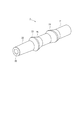
- the connector body 2 is formed in a tubular shape having a through hole 20 penetrating in the axial direction as shown in FIGS. 2 and 3.
- the connector main body 2 is provided on the distal end side in the insertion direction with respect to the female connector 9, the insertion portion 22 inserted into the female connector 9, and the insertion portion 22.
- a second enlarged-diameter part 24 as an enlarged-diameter part having an enlarged diameter outside the part 22.
- the insertion portion 22 has a tapered shape whose outer diameter is reduced toward the distal end. This taper is a 6% taper conforming to ISO (International Organization for Standardization) 594.
- the first enlarged diameter portion 23 has an outer shape with a circular cross section.
- the first enlarged diameter portion 23 is formed in a tapered shape in which the inner diameter on the second enlarged diameter portion 24 side is gradually reduced, and the insertion portion 22 side is formed in a tapered shape having an obtuse angle than the second enlarged diameter portion 24 side.
- the second enlarged diameter portion 24 has an outer shape with an elliptical cross section.
- the second enlarged diameter portion 24 is formed in a tapered shape having an enlarged diameter over the outer periphery of the shaft portion 21 and the insertion portion 22 side and the second enlarged diameter portion 24 side having substantially the same inclination angle.
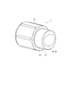
- the lock member 3 is formed in a tubular shape having a through hole 30 penetrating in the axial direction, as shown in FIGS.
- the lock member 3 includes a first cover portion 31 that covers the insertion portion 22 of the connector body 2 and a second cover portion that covers the shaft portion 21 of the connector body 2 when the lock member 3 is attached to the connector body 2. 32 and a stepped portion 33 located between the first covering portion 31 and the second covering portion 32.
- the first covering portion 31 is formed in a tubular shape having a larger outer diameter and inner diameter than the second covering portion 32.
- the inner diameter of the first covering portion 31 is set according to the outer diameter of the flange portion 91 of the female connector 9.
- a spiral thread 34 is formed on the inner surface of the first covering portion 31 along the central axis of the lock member 3. That is, the first covering portion 31 covers the flange portion 91 side portion of the female connector 9 when the lock member 3 locks the connector main body 2 and the female connector 9, and the screw thread 34 is the flange. It is comprised so that the part 91 may be engaged.
- the second covering part 32 is formed in a tubular shape having a smaller outer diameter and inner diameter than the first covering part 31.
- the second covering portion 32 is provided with an insertion hole 35 that passes through the second covering portion 32 and through which the connector main body 2 is inserted.
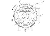
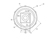
- the insertion hole 35 has a maximum inner dimension T11 larger than the maximum outer dimension T1 of the second enlarged diameter portion 24 of the connector body 2, and an inner dimension T12 passing through the center of gravity of the insertion hole 35 is as follows.
- the second enlarged diameter portion 24 has an elliptical inner shape smaller than the maximum outer dimension T1.
- the dimension in the major axis direction of the insertion hole 35 is formed larger than the dimension in the major axis direction of the second enlarged diameter part 24, and the dimension in the minor axis direction of the insertion hole 35 is the length of the second enlarged diameter part 24. It is formed smaller than the dimension in the axial direction.
- the insertion hole 35 constitutes a part of the through hole 30 and opens into the second covering portion 32 while being reduced in diameter toward the second covering portion 32 at the stepped portion 33.
- the step portion 33 includes a tapered contact surface 36 provided on the inner surface of the insertion hole 35 as shown in FIG.
- the abutment surface 36 abuts on the tapered surface 25 on the second enlarged diameter portion 24 side of the first enlarged diameter portion 23, and the insertion portion 22 contacts the tapered surface 25.
- a pressing force in the side direction is applied.
- the female connector 9 is formed in a tubular shape having a through hole 90 penetrating in the axial direction.
- the distal end of the female connector 9 in the insertion direction is formed in a taper shape in which the inner diameter of the through hole 90 increases toward the distal end (that is, the side close to the medical connector 1).
- a flange 91 that protrudes radially outward of the female connector 9 is formed at the tip of the female connector 9.
- the lock member 3 is attached to the connector body 2. That is, after the lock member 3 is rotated to the position shown in FIG. 6A with respect to the connector main body 2, the lock member 3 is slid toward the insertion portion 22 side of the connector main body 2 as shown in FIG. At this time, since the maximum outer dimension of the insertion portion 22 is located at the maximum inner dimension of the insertion hole 35 of the lock member 3, the lock member 3 can be slid and the lock member 3 is attached to the connector body 2. be able to.
- the lock member 3 When the lock between the female connector 9 and the medical connector 1 is released and the medical connector 1 is removed from the female connector 9, the lock member 3 is operated in the reverse procedure.
- the lock member 3 in the state where the medical connector 1 is detached from the female connector 9, the lock member 3 is at the position shown in FIG.
- the maximum external dimension portion of the insertion portion 22 of the connector main body 2 is positioned so as to protrude from the insertion hole 35 of the lock member 3, the insertion portion 22 and the lock member 3 interfere with each other as shown in FIG.
- the operation of the lock member 3 sliding toward the second covering portion 32 side of the connector body 2 is restricted. For this reason, it is possible to prevent the lock member 3 from being detached from the connector main body 2.
- the lock member 3 is detached from the connector body 2. That is, after the lock member 3 is rotated to the position shown in FIG. 6A with respect to the connector main body 2, the lock member 3 is slid to the second covering portion 32 side of the connector main body 2 as shown in FIG. 7. At this time, since the maximum external dimension portion of the insertion portion 22 of the connector main body 2 is positioned at the maximum inner shape portion of the insertion hole 35 of the lock member 3, the insertion portion 22 and the insertion hole 35 do not interfere with each other, and the connector main body. The lock member 3 can be detached from the member 2.
- the 2nd enlarged diameter part 24 of the connector main body 2 has the external shape of a cross-sectional ellipse, the external shape of the 2nd enlarged diameter part 24 can be made into a shape without an unevenness
- the second enlarged diameter portion 24 of the connector main body 2 has an outer shape having an elliptical cross section. Therefore, when the connector main body 2 is fixed to the patient's skin, the connector main body 2 The patient's skin can be prevented from being damaged.
- the insertion hole 35 of the lock member 3 has a maximum inner shape dimension that is larger than the maximum outer dimension of the second diameter-expanded portion 24, and an inner dimension that passes through the center of gravity of the insertion hole 35 is that of the second diameter-expanded portion 24. Since the inner shape is smaller than the maximum outer dimension, the lock member 3 can be slidable or non-slidable with respect to the connector body 2 according to the rotational position of the lock member 3. For this reason, the medical connector 1 can be used as a lock connector and a slip connector.
- the insertion hole 35 of the lock member 3 has an inner shape with an elliptical cross section, the inner shape of the insertion hole 35 can be a shape without irregularities. For this reason, since the workability of the lock member 3 can also be improved, the manufacturing cost of the medical connector 1 can be further suppressed.
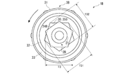
- the second enlarged diameter portion 24A has an outer shape in which a part of a circle is notched in a straight line in a cross-sectional view.
- the insertion hole 35A has an inner shape similar to the outer shape of the second enlarged diameter portion 24A. That is, the insertion hole 35A has a maximum inner dimension (long-axis dimension) T21 larger than the maximum outer dimension T2 of the second enlarged diameter portion 24A of the connector main body 2A and passes through the center of gravity of the insertion hole 35A. (Dimension in minor axis direction) T22 has a regular pentagonal inner shape smaller than the maximum outer dimension T2 of the second enlarged diameter portion 24A.
- FIGS. 10A and 10B a third embodiment of the present invention will be described with reference to FIGS. 10A and 10B.
- the shapes of the second enlarged diameter portion 24B of the connector main body 2B and the insertion hole 35B of the lock member 3B are different from those of the first and second embodiments.
- the second enlarged diameter portion 24B has an outer shape with a regular pentagonal cross section.
- the insertion hole 35B has a maximum inner shape dimension T31 larger than the maximum outer dimension T3 of the second enlarged diameter portion 24B of the connector body 2B, and an inner shape dimension T32 passing through the center of gravity of the insertion hole 35B is the second enlarged diameter portion. It has a regular pentagonal inner shape smaller than the maximum outer dimension T3 of 24B.
- the medical connector 1B can be used as a slip connector, and the lock member 3B is rotated to the position shown in FIG. 10B.
- the medical connector 1B can be used as a lock connector. According to the present embodiment described above, the same effects as those of the first and second embodiments can be obtained.
- the second enlarged diameter portion 24C has an outer shape having a square cross section.
- the maximum inner shape dimension T41 is larger than the maximum outer dimension T4 of the second enlarged diameter portion 24C of the connector body 2C, and the inner shape dimension T42 passing through the center of gravity of the insertion hole 35C is the second enlarged diameter portion. It has a square inner shape smaller than the maximum outer dimension T4 of 24C.
- the medical connector 1C can be used as a slip connector, and the lock member 3C is rotated to the position shown in FIG. 11B.
- the medical connector 1C can be used as a lock connector. Also by the present embodiment described above, the same effects as those of the first to third embodiments can be obtained.
- FIGS. 12A and 12B a fifth embodiment of the present invention will be described with reference to FIGS. 12A and 12B.
- the shapes of the second enlarged diameter portion 24D of the connector main body 2D and the insertion hole 35D of the lock member 3D are different from those of the first to fourth embodiments.
- the second enlarged diameter portion 24D has an outer shape having a regular triangular cross section.
- the insertion hole 35D has a maximum inner shape dimension T51 larger than the maximum outer dimension T5 of the second enlarged diameter portion 24D of the connector body 2D, and an inner shape dimension T52 passing through the center of gravity of the insertion hole 35D is the second enlarged diameter portion. It has an equilateral triangular inner shape smaller than the maximum outer dimension T5 of 24D.
- the medical connector 1D can be used as a slip connector, and the lock member 3D is rotated to the position shown in FIG. 12B.
- the medical connector 1D can be used as a lock connector. Also by the present embodiment described above, the same effects as those of the first to fourth embodiments can be obtained.
- FIGS. 13A and 13B a sixth embodiment of the present invention will be described with reference to FIGS. 13A and 13B.
- the shapes of the second enlarged diameter portion 24E of the connector main body 2E and the insertion hole 35E of the lock member 3E are different from those of the first to fifth embodiments.
- the second enlarged diameter portion 24E has an outer shape having a regular triangular cross section.
- the insertion hole 35E has an inner shape different from the outer shape of the second enlarged diameter portion 24E. That is, the insertion hole 35E has a maximum inner shape dimension T61 larger than the maximum outer dimension T6 of the second diameter-expanded portion 24E of the connector body 2E, and an inner shape dimension T62 passing through the center of gravity of the insertion hole 35E is the second diameter-expanded portion. It has a rectangular inner shape smaller than the maximum outer dimension T6 of 24E.
- the medical connector 1E can be used as a slip connector, and the lock member 3E is rotated to the position shown in FIG. 13B.
- the medical connector 1E can be used as a lock connector. According to the present embodiment as described above, the same effects as those of the first to fifth embodiments can be obtained.
- the present invention is not limited to the above-described embodiments, and modifications, improvements, and the like within the scope that can achieve the object of the present invention are included in the present invention.
- the lock members 3, 3A to 3E have the first cover portion 31 and the second cover portion 32 having different outer diameters, but the present invention is not limited to this.
- a region having a different inner diameter is formed in accordance with the outer diameter of the flange portion 91 of the female connector 9 and the outer diameter of the connector main bodies 2 and 2A to 2E.
- the outer diameter of the lock member may be uniform as long as the connector bodies 2, 2A to 3E can be pressed toward the female connector 9.
- the outer shape of the second enlarged diameter portion 24 and the inner diameter shape of the insertion hole 35 are each elliptical.
- the outer shape of the second enlarged diameter portion 24 is elliptical, and the inner diameter of the insertion hole is The shape may be a convex polygon or a shape obtained by cutting out a part of a circle in a straight line.
- the outer shape of the second enlarged diameter portion 24A and the inner diameter shape of the insertion hole 35A are each a shape in which a part of a circle is cut out linearly, but the outer shape of the second enlarged diameter portion 24A.
- the shape may be a shape in which a part of a circle is cut out linearly, and the inner diameter shape of the insertion hole may be an ellipse or a convex polygon.
- the outer shape of the second enlarged diameter portions 24B to 24D and the inner diameter shape of the insertion holes 35B to 35D are respectively convex polygons, but the second enlarged diameter portions 24B to 24D
- the outer shape may be a convex polygon
- the inner diameter shape of the insertion hole may be an ellipse or a shape obtained by notching a part of a circle in a straight line.
- the outer shape of the second enlarged diameter portions 24B to 24E and the inner shape of the insertion holes 35B to 35E are regular polygons such as a regular triangle, a square, and a regular pentagon.
- the regular polygon is not essential, and any shape can be adopted as long as it is a convex polygon.
- the outer shape of the second enlarged diameter portions 24B to 24E and the inner shape of the insertion holes 35B to 35E are regular polygons, the second enlarged diameter portions 24B to 24B with a smaller rotation angle as the number of angles increases. Since 24E easily passes through the insertion holes 35B to 35E, it is preferably up to a regular pentagon.
- the present invention can be used as a connector, for example, a connector provided at an end of a medical tube or the like and connected to a female connector provided in another tube or a three-way stopcock.
Landscapes
- Health & Medical Sciences (AREA)
- Heart & Thoracic Surgery (AREA)
- Pulmonology (AREA)
- Engineering & Computer Science (AREA)
- Anesthesiology (AREA)
- Biomedical Technology (AREA)
- Hematology (AREA)
- Life Sciences & Earth Sciences (AREA)
- Animal Behavior & Ethology (AREA)
- General Health & Medical Sciences (AREA)
- Public Health (AREA)
- Veterinary Medicine (AREA)
- Infusion, Injection, And Reservoir Apparatuses (AREA)
Description
本発明は、医療用コネクタに関し、詳しくは、メスコネクタに接続される医療用コネクタに関する。
従来、輸液等に用いられる医療用チューブ同士を接続する医療用コネクタが知られている(例えば、特許文献1参照)。
特許文献1に記載の医療用コネクタは、端部外周に突起部を有するメスコネクタに挿入されるオスルアーと、オスルアーに装着されるロックナット部とを備えている。この医療用コネクタは、メスコネクタにオスルアーを挿入した状態でロックナット部を回転させ、メスコネクタの突起部とロックナット部のねじ溝部とを係合させることで、ロックコネクタとして使用することができる。
特許文献1に記載の医療用コネクタは、端部外周に突起部を有するメスコネクタに挿入されるオスルアーと、オスルアーに装着されるロックナット部とを備えている。この医療用コネクタは、メスコネクタにオスルアーを挿入した状態でロックナット部を回転させ、メスコネクタの突起部とロックナット部のねじ溝部とを係合させることで、ロックコネクタとして使用することができる。
さらに、オスルアーには、径方向外側に突出する複数の突出部が形成され、ロックナット部の内面には、当該突出部に応じた複数の溝状部が形成されている。このため、各突出部の位置と各溝状部の位置とを合わせた状態で、ロックナット部をオスルアーの基端側にスライドさせて当該雄ルアーから離脱させることで、ロックナット部によるロックを行わずに、スリップコネクタとして使用することもできる。
しかしながら、特許文献1に記載されたような従来の医療用コネクタでは、オスルアーやロックナット部が複数の突出部や溝状部による凹凸形状を有しているため、加工が困難で、製造コストが増大するという問題がある。
本発明の目的は、製造コストを抑制しつつ、ロックコネクタおよびスリップコネクタとして使用できる医療用コネクタを提供することにある。
本発明の医療用コネクタは、管状のコネクタ本体と、前記コネクタ本体が挿通される挿通孔を有し、当該挿通孔に挿通された前記コネクタ本体をメスコネクタにロックするロック部材とを備え、前記コネクタ本体は、前記メスコネクタに対する挿入方向の先端側に設けられ、前記メスコネクタに挿入される挿入部と、前記挿入部よりも基端側に設けられ、前記挿入部よりも外側に拡径した拡径部とを備え、前記拡径部は、断面楕円形、断面凸多角形、および断面視で円の一部を直線状に切り欠いた形のうちのいずれかの外形形状を有し、前記挿通孔は、最大内形寸法が前記拡径部の最大外形寸法よりも大きく、かつ当該挿通孔の重心を通る内形寸法が前記拡径部の最大外形寸法よりも小さい内形形状を有していることを特徴とする。
本発明によれば、コネクタ本体の拡径部が断面楕円形等の外形形状を有するため、拡径部の外形形状を凹凸のない形状とすることができる。このため、コネクタ本体の加工性を向上させることができるので、医療用コネクタの製造コストを抑制することができる。
また、ロック部材の挿通孔は、最大内形寸法が拡径部の最大外形寸法よりも大きく、かつ当該挿通孔の重心を通る内形寸法が拡径部の最大外形寸法よりも小さい内形形状を有している。このため、ロック部材の回転位置に応じて、コネクタ本体に対してロック部材をスライド可能にしたり、スライド不能にしたりすることができる。このため、医療用コネクタをロックコネクタおよびスリップコネクタとして使用することができる。
また、ロック部材の挿通孔は、最大内形寸法が拡径部の最大外形寸法よりも大きく、かつ当該挿通孔の重心を通る内形寸法が拡径部の最大外形寸法よりも小さい内形形状を有している。このため、ロック部材の回転位置に応じて、コネクタ本体に対してロック部材をスライド可能にしたり、スライド不能にしたりすることができる。このため、医療用コネクタをロックコネクタおよびスリップコネクタとして使用することができる。
本発明の医療用コネクタにおいて、前記挿通孔は、断面楕円形の内形形状を有していることが好ましい。
本発明の医療用コネクタにおいて、前記挿通孔は、断面多角形の内形形状を有していることが好ましい。
本発明の医療用コネクタにおいて、前記挿通孔は、断面視で円の一部を直線状に切り欠いた内形形状を有していることが好ましい。
これらの本発明によれば、ロック部材の挿通孔が断面楕円形、断面凸多角形、または断面視で円の一部を直線状に切り欠いた形の内形形状を有しているため、当該挿通孔の内形形状を凹凸のない形状とすることができる。このため、ロック部材の加工性も向上させることができるので、医療用コネクタの製造コストをさらに抑制することができる。
以下、本発明の各実施形態を図面に基づいて説明する。
なお、第2実施形態以降において、次の第1実施形態で説明する構成部材と同じ構成部材および同様な機能を有する構成部材には、第1実施形態の構成部材と同じ符号を付し、それらの説明を省略または簡略化する。
なお、第2実施形態以降において、次の第1実施形態で説明する構成部材と同じ構成部材および同様な機能を有する構成部材には、第1実施形態の構成部材と同じ符号を付し、それらの説明を省略または簡略化する。
〔第1実施形態〕
医療用コネクタ1は、図1に示すように、コネクタ本体2と、コネクタ本体2に着脱自在に装着されるロック部材3とを備えている。この医療用コネクタ1は、コネクタ本体2がメスコネクタ9に挿入された状態で、ロック部材3によりコネクタ本体2をメスコネクタ9にロック可能に構成されている。
医療用コネクタ1は、図1に示すように、コネクタ本体2と、コネクタ本体2に着脱自在に装着されるロック部材3とを備えている。この医療用コネクタ1は、コネクタ本体2がメスコネクタ9に挿入された状態で、ロック部材3によりコネクタ本体2をメスコネクタ9にロック可能に構成されている。
コネクタ本体2は、図2および図3に示すように、軸線方向に貫通した貫通孔20を有する管状に形成されている。このコネクタ本体2は、略均一な外径および内径を有する軸部21と、メスコネクタ9に対する挿入方向の先端側に設けられ、当該メスコネクタ9に挿入される挿入部22と、挿入部22よりも基端側に設けられ、軸部21および挿入部22よりも外側に拡径した第1拡径部23と、第1拡径部23よりも基端側に設けられ、軸部21および挿入部22よりも外側に拡径した拡径部としての第2拡径部24とを備えている。
挿入部22は、先端に向かうにしたがって外径が縮径するテーパー形状を有している。このテーパーは、ISO(International Organization for Standardization)594に準拠した6%テーパーである。
第1拡径部23は、断面円形の外形形状を有している。この第1拡径部23は、第2拡径部24側の内径が次第に縮径するテーパー状に形成されるとともに、挿入部22側が第2拡径部24側よりも鈍角のテーパー状に形成されている。
第2拡径部24は、断面楕円形の外形形状を有している。この第2拡径部24は、軸部21の外周にわたって拡径するとともに、挿入部22側および第2拡径部24側がそれぞれ略同じ傾斜角を有するテーパー状に形成されている。
第1拡径部23は、断面円形の外形形状を有している。この第1拡径部23は、第2拡径部24側の内径が次第に縮径するテーパー状に形成されるとともに、挿入部22側が第2拡径部24側よりも鈍角のテーパー状に形成されている。
第2拡径部24は、断面楕円形の外形形状を有している。この第2拡径部24は、軸部21の外周にわたって拡径するとともに、挿入部22側および第2拡径部24側がそれぞれ略同じ傾斜角を有するテーパー状に形成されている。
ロック部材3は、図3から図5に示すように、軸線方向に貫通した貫通孔30を有する管状に形成されている。このロック部材3は、当該ロック部材3がコネクタ本体2に装着されたときに、コネクタ本体2の挿入部22を覆う第1被覆部31と、コネクタ本体2の軸部21を覆う第2被覆部32と、第1被覆部31および第2被覆部32の間に位置する段差部33とを備えている。
第1被覆部31は、第2被覆部32に比べて大きな外径および内径を有した管状に形成されている。この第1被覆部31の内径は、メスコネクタ9のフランジ部91の外径に合わせて設定されている。また、第1被覆部31の内面には、ロック部材3の中心軸に沿う螺旋状のねじ山34が形成されている。すなわち、第1被覆部31は、ロック部材3がコネクタ本体2とメスコネクタ9とをロックする際に、第1被覆部31がメスコネクタ9のフランジ部91側部分を覆い、ねじ山34がフランジ部91と係合するように構成されている。
第2被覆部32は、第1被覆部31に比べて小さな外径および内径を有した管状に形成されている。第2被覆部32には、当該第2被覆部32を貫通し、コネクタ本体2が挿通される挿通孔35が設けられている。挿通孔35は、図6Aに示すように、最大内形寸法T11がコネクタ本体2の第2拡径部24の最大外形寸法T1よりも大きく、当該挿通孔35の重心を通る内形寸法T12が第2拡径部24の最大外形寸法T1よりも小さい楕円形の内形形状を有している。すなわち、挿通孔35の長軸方向の寸法は、第2拡径部24の長軸方向の寸法よりも大きく形成され、挿通孔35の短軸方向の寸法は、第2拡径部24の長軸方向の寸法よりも小さく形成されている。この挿通孔35は、貫通孔30の一部を構成し、段差部33で第2被覆部32に向かって縮径しながら第2被覆部32内に開口する。
段差部33は、図3に示すように、挿通孔35の内面に設けられたテーパー状の当接面36を備えている。この当接面36は、コネクタ本体2をメスコネクタ9にロックする際に、第1拡径部23における第2拡径部24側のテーパー面25に当接し、当該テーパー面25に挿入部22側の方向(メスコネクタ9に近接する方向)の押圧力を作用させる。
メスコネクタ9は、軸線方向に貫通した貫通孔90を有する管状に形成されている。このメスコネクタ9の挿入方向先端部は、先端(すなわち、医療用コネクタ1に近接する側)に向かうに従って貫通孔90の内径が拡径するテーパー状に形成されている。また、メスコネクタ9の先端部には、当該メスコネクタ9の径方向外側に突出するフランジ部91が形成されている。
以下、医療用コネクタ1を使用する際の操作について説明する。
医療用コネクタ1をロックコネクタとして使用する際は、コネクタ本体2にロック部材3を装着する。すなわち、コネクタ本体2に対してロック部材3を図6Aに示す位置に回転操作した後、図7に示すように、ロック部材3をコネクタ本体2の挿入部22側にスライドさせる。この際、挿入部22の最大外形寸法部がロック部材3の挿通孔35の最大内形寸法部に位置するため、ロック部材3をスライドさせることができ、コネクタ本体2にロック部材3を装着することができる。
医療用コネクタ1をロックコネクタとして使用する際は、コネクタ本体2にロック部材3を装着する。すなわち、コネクタ本体2に対してロック部材3を図6Aに示す位置に回転操作した後、図7に示すように、ロック部材3をコネクタ本体2の挿入部22側にスライドさせる。この際、挿入部22の最大外形寸法部がロック部材3の挿通孔35の最大内形寸法部に位置するため、ロック部材3をスライドさせることができ、コネクタ本体2にロック部材3を装着することができる。
この状態で、コネクタ本体2の挿入部22を、メスコネクタ9の貫通孔90に挿入した後、ロック部材3を右回りに回転させる。これにより、ロック部材3がメスコネクタ9側に移動し、段差部33が第1拡径部23をメスコネクタ9側に押圧するため、コネクタ本体2の挿入部22がメスコネクタ9の貫通孔90に嵌合し、コネクタ本体2とメスコネクタ9とが密に接続される。また、ねじ山34とフランジ部91とが係合し、医療用コネクタ1がメスコネクタ9にロックされる。
メスコネクタ9と医療用コネクタ1とのロックを解除して、メスコネクタ9から医療用コネクタ1を取り外す際は、上記と反対の手順でロック部材3を操作する。
ここで、メスコネクタ9から医療用コネクタ1を取り外した状態では、ロック部材3の回転操作により、例えば、コネクタ本体2に対してロック部材3が図6Bに示す位置にある。この場合、コネクタ本体2の挿入部22の最大外形寸法部が、ロック部材3の挿通孔35からはみ出すように位置するため、図8に示すように、挿入部22とロック部材3とが干渉し、ロック部材3がコネクタ本体2の第2被覆部32側にスライドする動作が規制される。このため、ロック部材3がコネクタ本体2から離脱することを防止することができる。
ここで、メスコネクタ9から医療用コネクタ1を取り外した状態では、ロック部材3の回転操作により、例えば、コネクタ本体2に対してロック部材3が図6Bに示す位置にある。この場合、コネクタ本体2の挿入部22の最大外形寸法部が、ロック部材3の挿通孔35からはみ出すように位置するため、図8に示すように、挿入部22とロック部材3とが干渉し、ロック部材3がコネクタ本体2の第2被覆部32側にスライドする動作が規制される。このため、ロック部材3がコネクタ本体2から離脱することを防止することができる。
一方、医療用コネクタ1をスリップコネクタとして使用する際は、コネクタ本体2からロック部材3を離脱させる。すなわち、コネクタ本体2に対してロック部材3を図6Aに示す位置に回転操作した後、図7に示すように、ロック部材3をコネクタ本体2の第2被覆部32側にスライドさせる。この際、コネクタ本体2の挿入部22の最大外形寸法部がロック部材3の挿通孔35の最大内形寸法部に位置するため、挿入部22と挿通孔35とが干渉することなく、コネクタ本体2からロック部材3を離脱させることができる。
本実施形態によれば、次のような効果がある。
すなわち、コネクタ本体2の第2拡径部24が断面楕円形の外形形状を有するため、第2拡径部24の外形形状を凹凸のない形状とすることができる。このため、コネクタ本体2の加工性を向上させることができるので、医療用コネクタ1の製造コストを抑制することができる。
また、特に第1実施形態の場合には、コネクタ本体2の第2拡径部24が断面楕円形の外形形状を有するため、コネクタ本体2を患者の皮膚に固定した際に、コネクタ本体2により患者の皮膚が傷つくことを抑制することができる。
さらに、ロック部材3の挿通孔35は、最大内形寸法が第2拡径部24の最大外形寸法よりも大きく、かつ当該挿通孔35の重心を通る内形寸法が第2拡径部24の最大外形寸法よりも小さい内形形状を有しているため、ロック部材3の回転位置に応じて、コネクタ本体2に対してロック部材3をスライド可能にしたり、スライド不能にしたりすることができる。このため、医療用コネクタ1をロックコネクタおよびスリップコネクタとして使用することができる。
すなわち、コネクタ本体2の第2拡径部24が断面楕円形の外形形状を有するため、第2拡径部24の外形形状を凹凸のない形状とすることができる。このため、コネクタ本体2の加工性を向上させることができるので、医療用コネクタ1の製造コストを抑制することができる。
また、特に第1実施形態の場合には、コネクタ本体2の第2拡径部24が断面楕円形の外形形状を有するため、コネクタ本体2を患者の皮膚に固定した際に、コネクタ本体2により患者の皮膚が傷つくことを抑制することができる。
さらに、ロック部材3の挿通孔35は、最大内形寸法が第2拡径部24の最大外形寸法よりも大きく、かつ当該挿通孔35の重心を通る内形寸法が第2拡径部24の最大外形寸法よりも小さい内形形状を有しているため、ロック部材3の回転位置に応じて、コネクタ本体2に対してロック部材3をスライド可能にしたり、スライド不能にしたりすることができる。このため、医療用コネクタ1をロックコネクタおよびスリップコネクタとして使用することができる。
さらに、ロック部材3の挿通孔35が断面楕円形の内形形状を有しているため、当該挿通孔35の内形形状を凹凸のない形状とすることができる。このため、ロック部材3の加工性も向上させることができるので、医療用コネクタ1の製造コストをさらに抑制することができる。
〔第2実施形態〕
次に、本発明の第2実施形態を図9Aおよび図9Bに基づいて説明する。
本実施形態の医療用コネクタ1Aでは、コネクタ本体2Aの第2拡径部24Aおよびロック部材3Aの挿通孔35Aの形状が、第1実施形態と相違する。
次に、本発明の第2実施形態を図9Aおよび図9Bに基づいて説明する。
本実施形態の医療用コネクタ1Aでは、コネクタ本体2Aの第2拡径部24Aおよびロック部材3Aの挿通孔35Aの形状が、第1実施形態と相違する。
第2拡径部24Aは、図9Aに示すように、断面視で円の一部を直線状に切り欠いた外形形状を有している。
挿通孔35Aは、第2拡径部24Aの外形形状と同様の内形形状を有している。すなわち、挿通孔35Aは、最大内形寸法(長軸方向の寸法)T21がコネクタ本体2Aの第2拡径部24Aの最大外形寸法T2よりも大きく、当該挿通孔35Aの重心を通る内形寸法(短軸方向の寸法)T22が第2拡径部24Aの最大外形寸法T2よりも小さい正五角形の内形形状を有している。
挿通孔35Aは、第2拡径部24Aの外形形状と同様の内形形状を有している。すなわち、挿通孔35Aは、最大内形寸法(長軸方向の寸法)T21がコネクタ本体2Aの第2拡径部24Aの最大外形寸法T2よりも大きく、当該挿通孔35Aの重心を通る内形寸法(短軸方向の寸法)T22が第2拡径部24Aの最大外形寸法T2よりも小さい正五角形の内形形状を有している。
この医療用コネクタ1Aでは、コネクタ本体2Aに対してロック部材3Aを図9Aに示す位置に回転操作すれば、コネクタ本体2Aからロック部材3Aを離脱させすることができるので、医療用コネクタ1Aをスリップコネクタとして使用することができる。一方、コネクタ本体2Aに対してロック部材3Aを図9Bに示す位置に回転操作すれば、コネクタ本体2Aに対するロック部材3のスライド動作を規制することができ、医療用コネクタ1Aをロックコネクタとして使用することができる。
以上の本実施形態によっても、第1および第2実施形態と同様の効果が得られる。
以上の本実施形態によっても、第1および第2実施形態と同様の効果が得られる。
〔第3実施形態〕
次に、本発明の第3実施形態を図10Aおよび図10Bに基づいて説明する。
本実施形態の医療用コネクタ1Bでは、コネクタ本体2Bの第2拡径部24Bおよびロック部材3Bの挿通孔35Bの形状が、第1および第2実施形態と相違する。
次に、本発明の第3実施形態を図10Aおよび図10Bに基づいて説明する。
本実施形態の医療用コネクタ1Bでは、コネクタ本体2Bの第2拡径部24Bおよびロック部材3Bの挿通孔35Bの形状が、第1および第2実施形態と相違する。
第2拡径部24Bは、図10Aに示すように、断面正五角形の外形形状を有している。
一方、挿通孔35Bは、最大内形寸法T31がコネクタ本体2Bの第2拡径部24Bの最大外形寸法T3よりも大きく、当該挿通孔35Bの重心を通る内形寸法T32が第2拡径部24Bの最大外形寸法T3よりも小さい正五角形の内形形状を有している。
一方、挿通孔35Bは、最大内形寸法T31がコネクタ本体2Bの第2拡径部24Bの最大外形寸法T3よりも大きく、当該挿通孔35Bの重心を通る内形寸法T32が第2拡径部24Bの最大外形寸法T3よりも小さい正五角形の内形形状を有している。
そして、コネクタ本体2Bに対してロック部材3Bを図10Aに示す位置に回転操作すれば、医療用コネクタ1Bをスリップコネクタとして使用することができ、ロック部材3Bを図10Bに示す位置に回転操作すれば、医療用コネクタ1Bをロックコネクタとして使用することができる。
以上の本実施形態によっても、第1および第2実施形態と同様の効果が得られる。
以上の本実施形態によっても、第1および第2実施形態と同様の効果が得られる。
〔第4実施形態〕
次に、本発明の第4実施形態を図11Aおよび図11Bに基づいて説明する。
本実施形態の医療用コネクタ1Cでは、コネクタ本体2Cの第2拡径部24Cおよびロック部材3Cの挿通孔35Cの形状が、第1から第3実施形態と相違する。
次に、本発明の第4実施形態を図11Aおよび図11Bに基づいて説明する。
本実施形態の医療用コネクタ1Cでは、コネクタ本体2Cの第2拡径部24Cおよびロック部材3Cの挿通孔35Cの形状が、第1から第3実施形態と相違する。
第2拡径部24Cは、図11Aに示すように、断面正方形の外形形状を有している。
一方、挿通孔35Cは、最大内形寸法T41がコネクタ本体2Cの第2拡径部24Cの最大外形寸法T4よりも大きく、当該挿通孔35Cの重心を通る内形寸法T42が第2拡径部24Cの最大外形寸法T4よりも小さい正方形の内形形状を有している。
一方、挿通孔35Cは、最大内形寸法T41がコネクタ本体2Cの第2拡径部24Cの最大外形寸法T4よりも大きく、当該挿通孔35Cの重心を通る内形寸法T42が第2拡径部24Cの最大外形寸法T4よりも小さい正方形の内形形状を有している。
そして、コネクタ本体2Cに対してロック部材3Cを図11Aに示す位置に回転操作すれば、医療用コネクタ1Cをスリップコネクタとして使用することができ、ロック部材3Cを図11Bに示す位置に回転操作すれば、医療用コネクタ1Cをロックコネクタとして使用することができる。
以上の本実施形態によっても、第1から第3実施形態と同様の効果が得られる。
以上の本実施形態によっても、第1から第3実施形態と同様の効果が得られる。
〔第5実施形態〕
次に、本発明の第5実施形態を図12Aおよび図12Bに基づいて説明する。
本実施形態の医療用コネクタ1Dでは、コネクタ本体2Dの第2拡径部24Dおよびロック部材3Dの挿通孔35Dの形状が、第1から第4実施形態と相違する。
次に、本発明の第5実施形態を図12Aおよび図12Bに基づいて説明する。
本実施形態の医療用コネクタ1Dでは、コネクタ本体2Dの第2拡径部24Dおよびロック部材3Dの挿通孔35Dの形状が、第1から第4実施形態と相違する。
第2拡径部24Dは、図12Aに示すように、断面正三角形の外形形状を有している。
一方、挿通孔35Dは、最大内形寸法T51がコネクタ本体2Dの第2拡径部24Dの最大外形寸法T5よりも大きく、当該挿通孔35Dの重心を通る内形寸法T52が第2拡径部24Dの最大外形寸法T5よりも小さい正三角形の内形形状を有している。
一方、挿通孔35Dは、最大内形寸法T51がコネクタ本体2Dの第2拡径部24Dの最大外形寸法T5よりも大きく、当該挿通孔35Dの重心を通る内形寸法T52が第2拡径部24Dの最大外形寸法T5よりも小さい正三角形の内形形状を有している。
そして、コネクタ本体2Dに対してロック部材3Dを図12Aに示す位置に回転操作すれば、医療用コネクタ1Dをスリップコネクタとして使用することができ、ロック部材3Dを図12Bに示す位置に回転操作すれば、医療用コネクタ1Dをロックコネクタとして使用することができる。
以上の本実施形態によっても、第1から第4実施形態と同様の効果が得られる。
以上の本実施形態によっても、第1から第4実施形態と同様の効果が得られる。
〔第6実施形態〕
次に、本発明の第6実施形態を図13Aおよび図13Bに基づいて説明する。
本実施形態の医療用コネクタ1Eでは、コネクタ本体2Eの第2拡径部24Eおよびロック部材3Eの挿通孔35Eの形状が、第1から第5実施形態と相違する。
次に、本発明の第6実施形態を図13Aおよび図13Bに基づいて説明する。
本実施形態の医療用コネクタ1Eでは、コネクタ本体2Eの第2拡径部24Eおよびロック部材3Eの挿通孔35Eの形状が、第1から第5実施形態と相違する。
第2拡径部24Eは、図13Aに示すように、断面正三角形の外形形状を有している。
一方、挿通孔35Eは、第2拡径部24Eの外形形状とは異なる形の内形形状を有している。すなわち、挿通孔35Eは、最大内形寸法T61がコネクタ本体2Eの第2拡径部24Eの最大外形寸法T6よりも大きく、当該挿通孔35Eの重心を通る内形寸法T62が第2拡径部24Eの最大外形寸法T6よりも小さい長方形の内形形状を有している。
一方、挿通孔35Eは、第2拡径部24Eの外形形状とは異なる形の内形形状を有している。すなわち、挿通孔35Eは、最大内形寸法T61がコネクタ本体2Eの第2拡径部24Eの最大外形寸法T6よりも大きく、当該挿通孔35Eの重心を通る内形寸法T62が第2拡径部24Eの最大外形寸法T6よりも小さい長方形の内形形状を有している。
そして、コネクタ本体2Eに対してロック部材3Eを図13Aに示す位置に回転操作すれば、医療用コネクタ1Eをスリップコネクタとして使用することができ、ロック部材3Eを図13Bに示す位置に回転操作すれば、医療用コネクタ1Eをロックコネクタとして使用することができる。
以上の本実施形態によっても、第1から第5実施形態と同様の効果が得られる。
以上の本実施形態によっても、第1から第5実施形態と同様の効果が得られる。
なお、本発明は前述の実施形態に限定されるものではなく、本発明の目的を達成できる範囲での変形、改良等は本発明に含まれるものである。
例えば、前記各実施形態では、ロック部材3、3A~3Eは、それぞれ外径が異なる第1被覆部31および第2被覆部32を有していたが、本発明はこれに限らない。例えば、メスコネクタ9のフランジ部91の外径およびコネクタ本体2、2A~2Eの外径に応じて内径が異なる領域が形成され、コネクタ本体2、2A~2Eの一部に当接して、当該コネクタ本体2、2A~3Eをメスコネクタ9側に押圧できれば、ロック部材の外径は均一でもよい。
例えば、前記各実施形態では、ロック部材3、3A~3Eは、それぞれ外径が異なる第1被覆部31および第2被覆部32を有していたが、本発明はこれに限らない。例えば、メスコネクタ9のフランジ部91の外径およびコネクタ本体2、2A~2Eの外径に応じて内径が異なる領域が形成され、コネクタ本体2、2A~2Eの一部に当接して、当該コネクタ本体2、2A~3Eをメスコネクタ9側に押圧できれば、ロック部材の外径は均一でもよい。
前記第1実施形態では、第2拡径部24の外形形状および挿通孔35の内径形状がそれぞれ楕円形であったが、第2拡径部24の外形形状が楕円形で、挿通孔の内径形状が凸多角形または円の一部を直線状に切り欠いた形であってもよい。
前記第2実施形態では、第2拡径部24Aの外形形状および挿通孔35Aの内径形状がそれぞれ円の一部を直線状に切り欠いた形であったが、第2拡径部24Aの外形形状が円の一部を直線状に切り欠いた形で、挿通孔の内径形状が楕円形または凸多角形であってもよい。
前記第3から第5実施形態では、第2拡径部24B~24Dの外形形状および挿通孔35B~35Dの内径形状がそれぞれ凸多角形とされていたが、第2拡径部24B~24Dの外形形状が凸多角形で、挿通孔の内径形状が楕円形または円の一部を直線状に切り欠いた形であってもよい。
前記第3から第6実施形態では、第2拡径部24B~24Eの外形形状および挿通孔35B~35Eの内形形状が、正三角形、正方形、正5角形等の正多角形であったが、正多角形であることは必須ではなく、凸多角形であれば任意の形状を採用することができる。
なお、第2拡径部24B~24Eの外形形状および挿通孔35B~35Eの内形形状を正多角形とする場合、角数が多くなるに連れ、少ない回転角で第2拡径部24B~24Eが挿通孔35B~35Eを容易に通過してしまうため、正五角形までであることが好ましい。
なお、第2拡径部24B~24Eの外形形状および挿通孔35B~35Eの内形形状を正多角形とする場合、角数が多くなるに連れ、少ない回転角で第2拡径部24B~24Eが挿通孔35B~35Eを容易に通過してしまうため、正五角形までであることが好ましい。
本発明は、コネクタとして利用でき、例えば、医療用チューブ等の端部に設けられ、他のチューブや三方活栓等に設けられたメスコネクタに接続されるコネクタに利用できる。
1、1A~1E 医療用コネクタ
2、2A~2E コネクタ本体、
3、3A~3E ロック部材
9 メスコネクタ
22 挿入部
24、24A~24E 第2拡径部(拡径部)
35、35A~35E 挿通孔
2、2A~2E コネクタ本体、
3、3A~3E ロック部材
9 メスコネクタ
22 挿入部
24、24A~24E 第2拡径部(拡径部)
35、35A~35E 挿通孔
Claims (4)
- 管状のコネクタ本体と、
前記コネクタ本体が挿通される挿通孔を有し、当該挿通孔に挿通された前記コネクタ本体をメスコネクタにロックするロック部材とを備え、
前記コネクタ本体は、
前記メスコネクタに対する挿入方向の先端側に設けられ、前記メスコネクタに挿入される挿入部と、
前記挿入部よりも基端側に設けられ、前記挿入部よりも外側に拡径した拡径部とを備え、
前記拡径部は、断面楕円形、断面凸多角形、および断面視で円の一部を直線状に切り欠いた形のうちのいずれかの外形形状を有し、
前記挿通孔は、最大内形寸法が前記拡径部の最大外形寸法よりも大きく、かつ当該挿通孔の重心を通る内形寸法が前記拡径部の最大外形寸法よりも小さい内形形状を有している
ことを特徴とする医療用コネクタ。 - 請求項1に記載のコネクタにおいて、
前記挿通孔は、断面楕円形の内形形状を有している
ことを特徴とする医療用コネクタ。 - 請求項1に記載のコネクタにおいて、
前記挿通孔は、断面多角形の内形形状を有している
ことを特徴とする医療用コネクタ。 - 請求項1に記載のコネクタにおいて、
前記挿通孔は、断面視で円の一部を直線状に切り欠いた内形形状を有している
ことを特徴とする医療用コネクタ。
Priority Applications (1)
| Application Number | Priority Date | Filing Date | Title |
|---|---|---|---|
| PCT/JP2012/074886 WO2014049775A1 (ja) | 2012-09-27 | 2012-09-27 | 医療用コネクタ |
Applications Claiming Priority (1)
| Application Number | Priority Date | Filing Date | Title |
|---|---|---|---|
| PCT/JP2012/074886 WO2014049775A1 (ja) | 2012-09-27 | 2012-09-27 | 医療用コネクタ |
Publications (1)
| Publication Number | Publication Date |
|---|---|
| WO2014049775A1 true WO2014049775A1 (ja) | 2014-04-03 |
Family
ID=50387240
Family Applications (1)
| Application Number | Title | Priority Date | Filing Date |
|---|---|---|---|
| PCT/JP2012/074886 Ceased WO2014049775A1 (ja) | 2012-09-27 | 2012-09-27 | 医療用コネクタ |
Country Status (1)
| Country | Link |
|---|---|
| WO (1) | WO2014049775A1 (ja) |
Cited By (1)
| Publication number | Priority date | Publication date | Assignee | Title |
|---|---|---|---|---|
| WO2016202999A1 (de) * | 2015-06-19 | 2016-12-22 | Michael Schedler | Männlicher und weiblicher luer-verbinder und luer-verbindungssystem |
Citations (4)
| Publication number | Priority date | Publication date | Assignee | Title |
|---|---|---|---|---|
| US5113571A (en) * | 1990-01-29 | 1992-05-19 | Manska Wayne E | Method of manufacturing a connector for medical devices |
| JPH07148271A (ja) * | 1993-11-26 | 1995-06-13 | Jms Co Ltd | ロック型接続具 |
| JP2004081433A (ja) * | 2002-08-26 | 2004-03-18 | Nippon Sherwood Medical Industries Ltd | ロック型接続具 |
| JP2004523276A (ja) * | 2001-01-22 | 2004-08-05 | ベネテック インターナショナル インコーポレイテッド | 医療デバイスコネクタ取付具 |
-
2012
- 2012-09-27 WO PCT/JP2012/074886 patent/WO2014049775A1/ja not_active Ceased
Patent Citations (4)
| Publication number | Priority date | Publication date | Assignee | Title |
|---|---|---|---|---|
| US5113571A (en) * | 1990-01-29 | 1992-05-19 | Manska Wayne E | Method of manufacturing a connector for medical devices |
| JPH07148271A (ja) * | 1993-11-26 | 1995-06-13 | Jms Co Ltd | ロック型接続具 |
| JP2004523276A (ja) * | 2001-01-22 | 2004-08-05 | ベネテック インターナショナル インコーポレイテッド | 医療デバイスコネクタ取付具 |
| JP2004081433A (ja) * | 2002-08-26 | 2004-03-18 | Nippon Sherwood Medical Industries Ltd | ロック型接続具 |
Cited By (2)
| Publication number | Priority date | Publication date | Assignee | Title |
|---|---|---|---|---|
| WO2016202999A1 (de) * | 2015-06-19 | 2016-12-22 | Michael Schedler | Männlicher und weiblicher luer-verbinder und luer-verbindungssystem |
| CN107921249A (zh) * | 2015-06-19 | 2018-04-17 | 迈克尔·谢德勒 | 公鲁尔连接器、母鲁尔连接器和鲁尔连接系统 |
Similar Documents
| Publication | Publication Date | Title |
|---|---|---|
| JP6086153B2 (ja) | 流体用コネクタ、およびシリンジ | |
| JP4968607B2 (ja) | ルアー取付接続を改善するための方法及び装置 | |
| US10792465B2 (en) | Quick-release hubs for medical devices | |
| JP2007530171A5 (ja) | ||
| JP6968276B2 (ja) | 針遮蔽体除去器及び針遮蔽体除去器を備える薬剤送達デバイス | |
| CN104565606A (zh) | 用于连接到管的连接器 | |
| JP5923301B2 (ja) | コネクタ | |
| JP2012533436A (ja) | 針に特徴部を設ける方法 | |
| JP5678510B2 (ja) | 医療用コネクタ | |
| JP2012075495A (ja) | 医療用メスコネクタ | |
| US12129950B2 (en) | Device for connecting two tubular objects | |
| JP5018172B2 (ja) | プランジャーロッドとガスケットとの結合構造及びシリンジ | |
| US10206756B2 (en) | Tool for a dismantlable medical instrument | |
| JP2010213780A (ja) | 固定具、接続部材及び医療用具 | |
| US20180071507A1 (en) | Rotating connector | |
| TWI531357B (zh) | 植體移除裝置 | |
| WO2013157610A1 (ja) | ロック式ルアーテーパーコネクタ並びにそのロック式ルアーテーパーコネクタの雄コネクタおよび雌コネクタ | |
| WO2020184507A1 (ja) | トルクデバイス | |
| WO2018194770A3 (en) | TOOL CONNECTOR ASSEMBLY WITHOUT TOOL | |
| JP5843263B2 (ja) | ガイドワイヤ用把持具 | |
| JP6310127B1 (ja) | オスメスコネクタ接続機構 | |
| JP2016180480A (ja) | 支柱連結用継手及び支柱体 | |
| JP2012149731A (ja) | キャビネット連結部材 | |
| JP3183335U (ja) | カシメ用治具 | |
| JP2014208958A (ja) | シリンダー錠 |
Legal Events
| Date | Code | Title | Description |
|---|---|---|---|
| 121 | Ep: the epo has been informed by wipo that ep was designated in this application |
Ref document number: 12885830 Country of ref document: EP Kind code of ref document: A1 |
|
| NENP | Non-entry into the national phase |
Ref country code: DE |
|
| 122 | Ep: pct application non-entry in european phase |
Ref document number: 12885830 Country of ref document: EP Kind code of ref document: A1 |
|
| NENP | Non-entry into the national phase |
Ref country code: JP |