WO2014046263A1 - 画像処理装置、x線診断装置及び表示方法 - Google Patents
画像処理装置、x線診断装置及び表示方法 Download PDFInfo
- Publication number
- WO2014046263A1 WO2014046263A1 PCT/JP2013/075572 JP2013075572W WO2014046263A1 WO 2014046263 A1 WO2014046263 A1 WO 2014046263A1 JP 2013075572 W JP2013075572 W JP 2013075572W WO 2014046263 A1 WO2014046263 A1 WO 2014046263A1
- Authority
- WO
- WIPO (PCT)
- Prior art keywords
- image
- ray
- display
- superimposed
- unit
- Prior art date
- Legal status (The legal status is an assumption and is not a legal conclusion. Google has not performed a legal analysis and makes no representation as to the accuracy of the status listed.)
- Ceased
Links
Images


Classifications
-
- A—HUMAN NECESSITIES
- A61—MEDICAL OR VETERINARY SCIENCE; HYGIENE
- A61B—DIAGNOSIS; SURGERY; IDENTIFICATION
- A61B6/00—Apparatus or devices for radiation diagnosis; Apparatus or devices for radiation diagnosis combined with radiation therapy equipment
- A61B6/46—Arrangements for interfacing with the operator or the patient
- A61B6/461—Displaying means of special interest
- A61B6/463—Displaying means of special interest characterised by displaying multiple images or images and diagnostic data on one display
-
- A—HUMAN NECESSITIES
- A61—MEDICAL OR VETERINARY SCIENCE; HYGIENE
- A61B—DIAGNOSIS; SURGERY; IDENTIFICATION
- A61B6/00—Apparatus or devices for radiation diagnosis; Apparatus or devices for radiation diagnosis combined with radiation therapy equipment
- A61B6/12—Arrangements for detecting or locating foreign bodies
-
- A—HUMAN NECESSITIES
- A61—MEDICAL OR VETERINARY SCIENCE; HYGIENE
- A61B—DIAGNOSIS; SURGERY; IDENTIFICATION
- A61B6/00—Apparatus or devices for radiation diagnosis; Apparatus or devices for radiation diagnosis combined with radiation therapy equipment
- A61B6/46—Arrangements for interfacing with the operator or the patient
- A61B6/461—Displaying means of special interest
- A61B6/466—Displaying means of special interest adapted to display 3D data
-
- A—HUMAN NECESSITIES
- A61—MEDICAL OR VETERINARY SCIENCE; HYGIENE
- A61B—DIAGNOSIS; SURGERY; IDENTIFICATION
- A61B6/00—Apparatus or devices for radiation diagnosis; Apparatus or devices for radiation diagnosis combined with radiation therapy equipment
- A61B6/50—Apparatus or devices for radiation diagnosis; Apparatus or devices for radiation diagnosis combined with radiation therapy equipment specially adapted for specific body parts; specially adapted for specific clinical applications
- A61B6/503—Apparatus or devices for radiation diagnosis; Apparatus or devices for radiation diagnosis combined with radiation therapy equipment specially adapted for specific body parts; specially adapted for specific clinical applications for diagnosis of the heart
-
- A—HUMAN NECESSITIES
- A61—MEDICAL OR VETERINARY SCIENCE; HYGIENE
- A61B—DIAGNOSIS; SURGERY; IDENTIFICATION
- A61B6/00—Apparatus or devices for radiation diagnosis; Apparatus or devices for radiation diagnosis combined with radiation therapy equipment
- A61B6/52—Devices using data or image processing specially adapted for radiation diagnosis
- A61B6/5205—Devices using data or image processing specially adapted for radiation diagnosis involving processing of raw data to produce diagnostic data
-
- A—HUMAN NECESSITIES
- A61—MEDICAL OR VETERINARY SCIENCE; HYGIENE
- A61B—DIAGNOSIS; SURGERY; IDENTIFICATION
- A61B6/00—Apparatus or devices for radiation diagnosis; Apparatus or devices for radiation diagnosis combined with radiation therapy equipment
- A61B6/52—Devices using data or image processing specially adapted for radiation diagnosis
- A61B6/5211—Devices using data or image processing specially adapted for radiation diagnosis involving processing of medical diagnostic data
- A61B6/5217—Devices using data or image processing specially adapted for radiation diagnosis involving processing of medical diagnostic data extracting a diagnostic or physiological parameter from medical diagnostic data
-
- A—HUMAN NECESSITIES
- A61—MEDICAL OR VETERINARY SCIENCE; HYGIENE
- A61B—DIAGNOSIS; SURGERY; IDENTIFICATION
- A61B6/00—Apparatus or devices for radiation diagnosis; Apparatus or devices for radiation diagnosis combined with radiation therapy equipment
- A61B6/52—Devices using data or image processing specially adapted for radiation diagnosis
- A61B6/5211—Devices using data or image processing specially adapted for radiation diagnosis involving processing of medical diagnostic data
- A61B6/5229—Devices using data or image processing specially adapted for radiation diagnosis involving processing of medical diagnostic data combining image data of a patient, e.g. combining a functional image with an anatomical image
- A61B6/5247—Devices using data or image processing specially adapted for radiation diagnosis involving processing of medical diagnostic data combining image data of a patient, e.g. combining a functional image with an anatomical image combining images from an ionising-radiation diagnostic technique and a non-ionising radiation diagnostic technique, e.g. X-ray and ultrasound
-
- A—HUMAN NECESSITIES
- A61—MEDICAL OR VETERINARY SCIENCE; HYGIENE
- A61B—DIAGNOSIS; SURGERY; IDENTIFICATION
- A61B6/00—Apparatus or devices for radiation diagnosis; Apparatus or devices for radiation diagnosis combined with radiation therapy equipment
- A61B6/52—Devices using data or image processing specially adapted for radiation diagnosis
- A61B6/5258—Devices using data or image processing specially adapted for radiation diagnosis involving detection or reduction of artifacts or noise
- A61B6/5264—Devices using data or image processing specially adapted for radiation diagnosis involving detection or reduction of artifacts or noise due to motion
-
- A—HUMAN NECESSITIES
- A61—MEDICAL OR VETERINARY SCIENCE; HYGIENE
- A61B—DIAGNOSIS; SURGERY; IDENTIFICATION
- A61B6/00—Apparatus or devices for radiation diagnosis; Apparatus or devices for radiation diagnosis combined with radiation therapy equipment
- A61B6/52—Devices using data or image processing specially adapted for radiation diagnosis
- A61B6/5288—Devices using data or image processing specially adapted for radiation diagnosis involving retrospective matching to a physiological signal
-
- A—HUMAN NECESSITIES
- A61—MEDICAL OR VETERINARY SCIENCE; HYGIENE
- A61B—DIAGNOSIS; SURGERY; IDENTIFICATION
- A61B8/00—Diagnosis using ultrasonic, sonic or infrasonic waves
- A61B8/08—Clinical applications
- A61B8/0883—Clinical applications for diagnosis of the heart
-
- A—HUMAN NECESSITIES
- A61—MEDICAL OR VETERINARY SCIENCE; HYGIENE
- A61B—DIAGNOSIS; SURGERY; IDENTIFICATION
- A61B8/00—Diagnosis using ultrasonic, sonic or infrasonic waves
- A61B8/46—Ultrasonic, sonic or infrasonic diagnostic devices with special arrangements for interfacing with the operator or the patient
- A61B8/461—Displaying means of special interest
- A61B8/463—Displaying means of special interest characterised by displaying multiple images or images and diagnostic data on one display
-
- A—HUMAN NECESSITIES
- A61—MEDICAL OR VETERINARY SCIENCE; HYGIENE
- A61B—DIAGNOSIS; SURGERY; IDENTIFICATION
- A61B8/00—Diagnosis using ultrasonic, sonic or infrasonic waves
- A61B8/46—Ultrasonic, sonic or infrasonic diagnostic devices with special arrangements for interfacing with the operator or the patient
- A61B8/461—Displaying means of special interest
- A61B8/466—Displaying means of special interest adapted to display 3D data
-
- A—HUMAN NECESSITIES
- A61—MEDICAL OR VETERINARY SCIENCE; HYGIENE
- A61B—DIAGNOSIS; SURGERY; IDENTIFICATION
- A61B8/00—Diagnosis using ultrasonic, sonic or infrasonic waves
- A61B8/52—Devices using data or image processing specially adapted for diagnosis using ultrasonic, sonic or infrasonic waves
- A61B8/5215—Devices using data or image processing specially adapted for diagnosis using ultrasonic, sonic or infrasonic waves involving processing of medical diagnostic data
- A61B8/5238—Devices using data or image processing specially adapted for diagnosis using ultrasonic, sonic or infrasonic waves involving processing of medical diagnostic data for combining image data of patient, e.g. merging several images from different acquisition modes into one image
- A61B8/5261—Devices using data or image processing specially adapted for diagnosis using ultrasonic, sonic or infrasonic waves involving processing of medical diagnostic data for combining image data of patient, e.g. merging several images from different acquisition modes into one image combining images from different diagnostic modalities, e.g. ultrasound and X-ray
-
- G—PHYSICS
- G06—COMPUTING OR CALCULATING; COUNTING
- G06T—IMAGE DATA PROCESSING OR GENERATION, IN GENERAL
- G06T11/00—2D [Two Dimensional] image generation
- G06T11/60—Editing figures and text; Combining figures or text
-
- G—PHYSICS
- G16—INFORMATION AND COMMUNICATION TECHNOLOGY [ICT] SPECIALLY ADAPTED FOR SPECIFIC APPLICATION FIELDS
- G16H—HEALTHCARE INFORMATICS, i.e. INFORMATION AND COMMUNICATION TECHNOLOGY [ICT] SPECIALLY ADAPTED FOR THE HANDLING OR PROCESSING OF MEDICAL OR HEALTHCARE DATA
- G16H50/00—ICT specially adapted for medical diagnosis, medical simulation or medical data mining; ICT specially adapted for detecting, monitoring or modelling epidemics or pandemics
- G16H50/30—ICT specially adapted for medical diagnosis, medical simulation or medical data mining; ICT specially adapted for detecting, monitoring or modelling epidemics or pandemics for calculating health indices; for individual health risk assessment
-
- A—HUMAN NECESSITIES
- A61—MEDICAL OR VETERINARY SCIENCE; HYGIENE
- A61B—DIAGNOSIS; SURGERY; IDENTIFICATION
- A61B8/00—Diagnosis using ultrasonic, sonic or infrasonic waves
- A61B8/42—Details of probe positioning or probe attachment to the patient
- A61B8/4245—Details of probe positioning or probe attachment to the patient involving determining the position of the probe, e.g. with respect to an external reference frame or to the patient
- A61B8/4263—Details of probe positioning or probe attachment to the patient involving determining the position of the probe, e.g. with respect to an external reference frame or to the patient using sensors not mounted on the probe, e.g. mounted on an external reference frame
-
- A—HUMAN NECESSITIES
- A61—MEDICAL OR VETERINARY SCIENCE; HYGIENE
- A61B—DIAGNOSIS; SURGERY; IDENTIFICATION
- A61B8/00—Diagnosis using ultrasonic, sonic or infrasonic waves
- A61B8/48—Diagnostic techniques
- A61B8/485—Diagnostic techniques involving measuring strain or elastic properties
-
- A—HUMAN NECESSITIES
- A61—MEDICAL OR VETERINARY SCIENCE; HYGIENE
- A61B—DIAGNOSIS; SURGERY; IDENTIFICATION
- A61B8/00—Diagnosis using ultrasonic, sonic or infrasonic waves
- A61B8/48—Diagnostic techniques
- A61B8/488—Diagnostic techniques involving Doppler signals
-
- G—PHYSICS
- G06—COMPUTING OR CALCULATING; COUNTING
- G06T—IMAGE DATA PROCESSING OR GENERATION, IN GENERAL
- G06T2207/00—Indexing scheme for image analysis or image enhancement
- G06T2207/10—Image acquisition modality
- G06T2207/10016—Video; Image sequence
-
- G—PHYSICS
- G06—COMPUTING OR CALCULATING; COUNTING
- G06T—IMAGE DATA PROCESSING OR GENERATION, IN GENERAL
- G06T2207/00—Indexing scheme for image analysis or image enhancement
- G06T2207/10—Image acquisition modality
- G06T2207/10116—X-ray image
Definitions
- Embodiments described herein relate generally to an image processing apparatus, an X-ray diagnostic apparatus, and a display method.
- CRT Cardiac Resynchronization Therapy
- the timing to the myocardium surrounding the ventricle becomes abnormal, the left and right heart walls do not move simultaneously, the ventricle cannot contract in a timely manner, and blood is not pumped out. Used for treatment of diseases that become sufficient.
- CRT is a treatment method in which an electrode is placed in a site where the motion of the heart is bad (asynchronous site: Latest Activation) so that the heart contracts synchronously.
- the CRT specifies an asynchronous part by strain analysis by an ultrasonic diagnostic apparatus, and an electrode is placed in a vein closest to the asynchronous part while referring to an X-ray image taken by the X-ray diagnostic apparatus.
- the electrodes placed in this way cause stimulation potential to flow in a timely manner so that the myocardium contracts in a timely manner to control the movement of the ventricles.
- the problem to be solved by the present invention is to provide an image processing apparatus, an X-ray diagnostic apparatus, and a display method that can display an image with high visibility in a superimposed image of an X-ray image and another medical image. That is.
- the image processing apparatus includes a determination unit and a display control unit.
- the determination unit determines whether to display the X-ray image and the second image, which are the first images, as moving images or still images based on the display state.
- the display control unit converts the X-ray image and the second image into a combination of a moving image and a moving image, a combination of a moving image and a still image, or a still image and a moving image. Control is performed so that the superimposed image superimposed by any one of the combinations is displayed on the display unit.
- FIG. 1 is a diagram illustrating an example of a configuration of an image processing system according to the first embodiment.
- FIG. 2 is a diagram illustrating an example of the configuration of the X-ray diagnostic apparatus according to the first embodiment.
- FIG. 3 is a diagram illustrating an example of the configuration of the ultrasonic diagnostic apparatus according to the first embodiment.
- FIG. 4 is a diagram illustrating an example of a processing result by the volume data processing unit according to the first embodiment.
- FIG. 5A is a diagram for explaining an example of processing by the volume data processing unit according to the first embodiment.
- FIG. 5B is a diagram illustrating an example of an image generated by the volume data processing unit according to the first embodiment.
- FIG. 6 is a diagram illustrating an example of the configuration of the image processing apparatus according to the first embodiment.
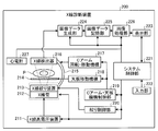
- FIG. 1 is a diagram illustrating an example of a configuration of an image processing system according to the first embodiment.
- FIG. 2 is a diagram illustrating an example of the configuration of the X-ray diagnostic apparatus according to
- FIG. 7 is a diagram for explaining an example of a fusion image display state according to the first embodiment.
- FIG. 8 is a diagram for explaining an example of processing by the alignment unit 151 according to the first embodiment.
- FIG. 9 is a diagram illustrating an example of a combination of fusion images determined by the determination unit according to the first embodiment.
- FIG. 10A is a diagram for explaining an ultrasound image used by the display control unit according to the first embodiment.
- FIG. 10B is a diagram for explaining an X-ray image used for real-time display by the display control unit according to the first embodiment.
- FIG. 10C is a diagram for explaining an ultrasonic image used by the display control unit according to the first embodiment.
- FIG. 11 is a diagram illustrating an example of display control processing by the display control unit according to the first embodiment.
- FIG. 12 is a flowchart illustrating a processing procedure performed by the image processing apparatus according to the first embodiment.
- FIG. 13 is a flowchart illustrating a procedure of synchronization processing by the image processing apparatus according to the first embodiment.
- FIG. 14A is a diagram illustrating an example of display control processing by the display control unit according to the second embodiment.
- FIG. 14B is a diagram illustrating an example of display control processing by the display control unit according to the second embodiment.
- FIG. 1 is a diagram illustrating an example of a configuration of an image processing system according to the first embodiment.
- the case where an ultrasonic image is used as another medical image to be superimposed on the X-ray image will be described as an example, but the embodiment is not limited to this.
- the image processing system 1 includes an image processing apparatus 100, an X-ray diagnostic apparatus 200, an ultrasonic diagnostic apparatus 300, and an image storage apparatus 400.
- Each apparatus illustrated in FIG. 1 is in a state where it can communicate with each other directly or indirectly by, for example, an in-hospital LAN (Local Area Network) installed in a hospital.
- an in-hospital LAN Local Area Network
- PACS Picture Archiving and Communication System
- each apparatus transmits and receives medical images and the like according to the DICOM (Digital Imaging and Communications in Medicine) standard.
- DICOM Digital Imaging and Communications in Medicine
- the X-ray diagnostic apparatus 200 and the ultrasonic diagnostic apparatus 300 collect an X-ray image and an ultrasonic image according to the operations of the respective engineers.
- the image processing apparatus 100 displays the ultrasound image aligned with the X-ray image, so that the doctor can accurately place the electrode at the indwelling position planned by the ultrasound diagnostic apparatus in the CRT. Become.
- the image storage device 400 is a database that stores medical images. Specifically, the image storage apparatus 400 according to the first embodiment stores an X-ray image transmitted from the X-ray diagnostic apparatus 200, an ultrasonic image transmitted from the ultrasonic diagnostic apparatus 300, and the like in a storage unit. And store it. In other words, the image processing apparatus 100 according to the first embodiment may receive image data directly from the X-ray diagnostic apparatus 200 and the ultrasonic diagnostic apparatus 300, or the image once stored in the image storage apparatus 400 may be used. It may be acquired.
- FIG. 2 is a diagram illustrating an example of the configuration of the X-ray diagnostic apparatus 200 according to the first embodiment.
- the X-ray diagnostic apparatus 200 according to the first embodiment includes an X-ray high voltage device 211, an X-ray tube 212, an X-ray diaphragm device 213, a top plate 214, and a C arm 215. And an X-ray detector 216.
- the X-ray diagnostic apparatus 200 according to the first embodiment includes a C-arm rotation / movement mechanism 217, a top-plate movement mechanism 218, a C-arm / top-plate mechanism control unit 219, an aperture control unit 220, and a system.
- the X-ray diagnostic apparatus 200 includes an image data generation unit 224, an image data storage unit 225, an image processing unit 226, and an electrocardiograph 227.
- the X-ray high voltage device 211 generates a high voltage under the control of the system control unit 221 and supplies the generated high voltage to the X-ray tube 212.
- the X-ray tube 212 generates X-rays using the high voltage supplied from the X-ray high voltage device 211.
- the X-ray diaphragm device 213 narrows the X-ray generated by the X-ray tube 212 under the control of the diaphragm controller 220 so that the region of interest of the subject P is selectively irradiated.
- the X-ray diaphragm device 213 has four slidable diaphragm blades.
- the X-ray diaphragm 213 narrows the X-rays generated by the X-ray tube 212 and irradiates the subject P by sliding these diaphragm blades under the control of the diaphragm controller 220.
- the top plate 214 is a bed on which the subject P is placed, and is arranged on a bed (not shown). The subject P is not included in the X-ray diagnostic apparatus 200.
- the X-ray detector 216 detects X-rays that have passed through the subject P.
- the X-ray detector 216 has detection elements arranged in a matrix. Each detection element converts the X-rays that have passed through the subject P into electrical signals and accumulates them, and transmits the accumulated electrical signals to the image data generation unit 224.
- the C-arm 215 holds the X-ray tube 212, the X-ray diaphragm device 213, and the X-ray detector 216.
- the X-ray tube 212, the X-ray diaphragm device 213, and the X-ray detector 216 are arranged so as to face each other with the subject P sandwiched by the C arm 215.
- the C-arm rotating / moving mechanism 217 is a mechanism for rotating and moving the C-arm 215, and the top board moving mechanism 218 is a mechanism for moving the top board 214.
- the C arm / top plate mechanism control unit 219 controls the C arm rotation / movement mechanism 217 and the top plate movement mechanism 218 under the control of the system control unit 221, thereby rotating and moving the C arm 215, the top plate 214. Adjust the movement of.
- the aperture control unit 220 controls the X-ray irradiation range irradiated to the subject P by adjusting the aperture of the aperture blades of the X-ray aperture device 213 under the control of the system control unit 221. .
- the electrocardiograph 227 acquires an electrocardiogram (ECG: Electrocardiogram) of the subject P to which a terminal (not shown) is attached, and the acquired electrocardiogram waveform together with time information, the image data generation unit 224 and the image processing unit 226. Send to.
- ECG Electrocardiogram
- the image data generation unit 224 generates an X-ray image using the electrical signal converted from the X-ray by the X-ray detector 216, and stores the generated X-ray image in the image data storage unit 225.
- the image data generation unit 224 performs current / voltage conversion, A (Analog) / D (Digital) conversion, and parallel-serial conversion on the electrical signal received from the X-ray detector 216 to convert the X-ray image. Generate. *
- the image data generation unit 224 generates a plurality of X-ray images obtained by photographing the heart of the subject P into which the contrast agent has been injected in time series.
- the image data generation unit 224 stores the generated X-ray image in the image data storage unit 225.
- the image data generation unit 224 in this embodiment receives the generated X-ray image from the electrocardiograph 227.
- the electrocardiogram waveform and the time information are stored in the image data storage unit 225 in association with each other.
- the image data storage unit 225 stores the X-ray image generated by the image data generation unit 224.
- the image data storage unit 225 stores the X-ray image generated by the image data generation unit 224 in association with the imaging time and the electrocardiogram waveform at the imaging time.
- the image processing unit 226 performs various image processes on the image data stored in the image data storage unit 225.
- the image processing unit 226 generates a moving image by processing a plurality of X-ray images in time series stored in the image data storage unit 225.
- the input unit 222 receives various instructions from an operator such as a doctor or engineer who operates the X-ray diagnostic apparatus 200.
- the input unit 222 includes a mouse, a keyboard, a button, a trackball, a joystick, and the like.
- the input unit 222 transfers the instruction received from the operator to the system control unit 221.
- the input unit 222 receives an instruction for turning on the power of the X-ray diagnostic apparatus 200.
- the display unit 223 displays a GUI (Graphical User Interface) for receiving an instruction from the operator, image data stored in the image data storage unit 225, and the like.
- GUI Graphic User Interface
- the display unit 223 includes a monitor.
- the display unit 223 may include a plurality of monitors.
- the system control unit 221 controls the operation of the entire X-ray diagnostic apparatus 200.
- the system control unit 221 controls the X-ray high voltage apparatus 211 according to the operator's instruction transferred from the input unit 222 and adjusts the voltage supplied to the X-ray tube 212, whereby the subject P is controlled. Controls X-ray dose and ON / OFF.
- the system control unit 221 controls the C arm / top plate mechanism control unit 219 in accordance with an instruction from the operator, and adjusts the rotation and movement of the C arm 215 and the movement of the top plate 214.
- the system control unit 221 controls the aperture control unit 220 in accordance with an instruction from the operator, and adjusts the aperture of the aperture blades included in the X-ray aperture device 213 to irradiate the subject P.
- the X-ray irradiation range is controlled.
- system control unit 221 controls image data generation processing by the image data generation unit 224, image processing by the image processing unit 226, analysis processing, and the like according to an instruction from the operator. Further, the system control unit 221 performs control so that a GUI for receiving an instruction from the operator, an image stored in the image data storage unit 225, and the like are displayed on the monitor of the display unit 223.
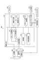
- FIG. 3 is a diagram for explaining the configuration of the ultrasonic diagnostic apparatus 300 according to the first embodiment.
- the ultrasonic diagnostic apparatus 300 according to the first embodiment includes an apparatus main body 310, an ultrasonic probe 320, an input device 330, a monitor 340, a transmitter 351, a position sensor 352, A control device 353 and an electrocardiograph 360 are provided.
- the ultrasonic probe 320 includes a plurality of piezoelectric vibrators, and the plurality of piezoelectric vibrators generate ultrasonic waves based on a drive signal supplied from a transmission / reception unit 311 included in the apparatus main body 310 to be described later. A reflected wave from the specimen P is received and converted into an electric signal.
- the ultrasonic probe 320 includes a matching layer provided in the piezoelectric vibrator, a backing material that prevents propagation of ultrasonic waves from the piezoelectric vibrator to the rear, and the like.
- the ultrasonic probe 320 is a sector type, linear type or convex type ultrasonic probe.
- the transmitted ultrasonic waves are reflected one after another at the discontinuous surface of the acoustic impedance in the body tissue of the subject P, and the ultrasonic probe is used as a reflected wave signal.
- 320 is received by a plurality of piezoelectric vibrators 320.
- the amplitude of the received reflected wave signal depends on the difference in acoustic impedance at the discontinuous surface where the ultrasonic wave is reflected.
- the reflected wave signal when the transmitted ultrasonic pulse is reflected by the moving blood flow or the surface of the heart wall depends on the velocity component of the moving object in the ultrasonic transmission direction due to the Doppler effect. , Subject to frequency shift.
- an ultrasonic probe 320 that mechanically swings a plurality of piezoelectric vibrators of a one-dimensional ultrasonic probe or a two-dimensional ultrasonic probe in which a plurality of piezoelectric vibrators are arranged in a two-dimensional grid.
- the object P is scanned three-dimensionally by the ultrasonic probe 320.
- the input device 330 includes a trackball, a switch, a button, a touch command screen, and the like, receives various setting requests from an operator of the ultrasonic diagnostic apparatus 300, and transfers the received various setting requests to the apparatus main body 310. .
- the input device 330 accepts various operations related to alignment between an ultrasound image and an X-ray image.
- the monitor 340 displays a GUI (Graphical User Interface) for the operator of the ultrasound diagnostic apparatus 300 to input various setting requests using the input device 330, or the ultrasound image generated in the apparatus main body 310 and the X A line CT image or the like is displayed in parallel.
- GUI Graphic User Interface
- Transmitter 351 transmits a reference signal.
- the transmitter 351 is disposed at an arbitrary position, and forms a magnetic field toward the outside centering on its own device.
- the position sensor 352 acquires position information on the three-dimensional space by receiving the reference signal.
- the position sensor 352 is attached to the surface of the ultrasonic probe 320, detects a three-dimensional magnetic field formed by the transmitter 351, converts the detected magnetic field information into a signal, and controls the control device 353. Output to.
- the control device 353 Based on the signal received from the position sensor 352, the control device 353 calculates the coordinates and orientation of the position sensor 352 in the space with the transmitter 351 as the origin, and the calculated coordinates and orientation are described later. Output to.
- the diagnosis of the subject P is performed in a magnetic field area where the position sensor 352 attached to the ultrasonic probe 320 can accurately detect the magnetic field of the transmitter 351.
- a magnetic sensor is used as a sensor for acquiring position information will be described, but the embodiment is not limited to this.
- an infrared sensor, an optical sensor, a camera, or the like may be used instead of the magnetic sensor.
- the electrocardiograph 360 is connected to the apparatus main body 310 and acquires an electrocardiogram (ECG: Electrocardiogram) of the subject P on which ultrasonic scanning is performed.
- ECG Electrocardiogram
- the electrocardiograph 360 transmits the acquired electrocardiogram waveform and time information to the apparatus main body 310.
- the apparatus main body 310 is an apparatus that generates an ultrasonic image based on the reflected wave received by the ultrasonic probe 320. As shown in FIG. 3, the transmission / reception unit 311, the B-mode processing unit 312, and the Doppler processing unit 313 are used. An image generation unit 314, an image memory 315, a control unit 316, an internal storage unit 317, an interface unit 318, and a volume data processing unit 319.
- the transmission / reception unit 311 includes a trigger generation circuit, a delay circuit, a pulsar circuit, and the like, and supplies a drive signal to the ultrasonic probe 320.
- the pulsar circuit repeatedly generates rate pulses for forming transmission ultrasonic waves at a predetermined rate frequency.
- the delay circuit also sets a delay time for each piezoelectric vibrator necessary for determining the transmission directivity by focusing the ultrasonic wave generated from the ultrasonic probe 320 into a beam, and for each rate pulse generated by the pulser circuit.
- the trigger generation circuit applies a drive signal (drive pulse) to the ultrasonic probe 320 at a timing based on the rate pulse. In other words, the delay circuit arbitrarily adjusts the transmission direction from the piezoelectric vibrator surface by changing the delay time given to each rate pulse.
- the transmission / reception unit 311 includes an amplifier circuit, an A / D converter, an adder, and the like, and performs various processes on the reflected wave signal received by the ultrasonic probe 320 to generate reflected wave data.
- the amplifier circuit amplifies the reflected wave signal for each channel and performs gain correction processing, and the A / D converter is necessary for A / D converting the gain-corrected reflected wave signal to determine the reception directivity.
- the adder performs an addition process of the reflected wave signal processed by the A / D converter to generate reflected wave data. By the addition processing of the adder, the reflection component from the direction corresponding to the reception directivity of the reflected wave signal is emphasized.
- the transmission / reception unit 311 controls transmission directivity and reception directivity in transmission / reception of ultrasonic waves.
- the transmission / reception unit 311 has a function capable of instantaneously changing delay information, a transmission frequency, a transmission drive voltage, the number of aperture elements, and the like under the control of a control unit 316 described later.
- the change of the transmission drive voltage is realized by a linear amplifier type oscillation circuit capable of instantaneously switching values or a mechanism for electrically switching a plurality of power supply units.
- the transmission / reception unit 311 can also transmit and receive different waveforms for each frame or rate.
- the B-mode processing unit 312 receives reflected wave data that is a processed reflected wave signal that has been subjected to gain correction processing, A / D conversion processing, and addition processing from the transmission / reception unit 311, and performs logarithmic amplification, envelope detection processing, and the like. As a result, data (B mode data) in which the signal intensity is expressed by brightness is generated. *
- the Doppler processing unit 313 performs frequency analysis on velocity information from the reflected wave data received from the transmission / reception unit 311, extracts blood flow, tissue, and contrast agent echo components due to the Doppler effect, and mobile object information such as average velocity, dispersion, and power Is generated for multiple points (Doppler data).
- the image generation unit 314 generates an ultrasonic image from the B mode data generated by the B mode processing unit 312 and the Doppler data generated by the Doppler processing unit 313. Specifically, the image generation unit 314 converts (scan converts) the scanning line signal sequence of the ultrasonic scan into a scanning line signal sequence of a video format typified by a television or the like, so that B mode data or Doppler data is obtained.
- the ultrasonic image for display (B mode image or Doppler image) is generated from the above.
- the image generation unit 314 associates the generated ultrasound image with the electrocardiogram waveform and time information received from the electrocardiograph 360 and stores them in the image memory 315.
- the image memory 315 stores image data such as a contrast image and a tissue image generated by the image generation unit 314.
- the image memory 315 stores an output signal (RF: Radio Frequency) immediately after passing through the transmission / reception unit 311, an image luminance signal, various raw data, image data acquired via a network, and the like as necessary.
- the data format of the image data stored in the image memory 315 is generated by the B-mode processing unit 312 and the Doppler processing unit 313 even if it is a data format after video format conversion displayed on the monitor 340 by the control unit 316 described later.
- the data format before coordinate conversion may be Raw data.
- the control unit 316 controls the entire processing in the ultrasonic diagnostic apparatus 300. Specifically, the control unit 316 transmits / receives the transmission / reception units 311, B based on various setting requests input from the operator via the input device 330 and various control programs and various setting information read from the internal storage unit 317. The processing of the mode processing unit 312, the Doppler processing unit 313, and the image generation unit 314 is controlled, and the ultrasonic image stored in the image memory 315 is controlled to be displayed on the monitor 340. In addition, the control unit 316, for example, in accordance with DICOM (Digital Imaging and Communications in Medicine) standard, 3D image data (volume data) of other modalities (for example, X-ray CT apparatus, MRI apparatus, etc.) Send and receive via.
- DICOM Digital Imaging and Communications in Medicine
- the internal storage unit 317 stores various data such as a control program for performing ultrasonic transmission / reception, image processing, and display processing, diagnostic information (for example, patient ID, doctor's findings, etc.), and a diagnostic protocol. Further, the internal storage unit 317 is also used for storing images stored in the image memory 315 as necessary.
- the interface unit 318 is an interface that controls the exchange of various information among the input device 330, the control device 353, and the device main body 310. For example, the interface unit 318 controls the transfer of the position information acquired by the control device 353 to the control unit 316.
- the volume data processing unit 319 executes various processes related to strain analysis. Specifically, an image in which a state of excitation propagation in the heart is depicted is generated by 3D Wall Motion Tracking.
- the ultrasonic diagnostic apparatus 300 according to the first embodiment first generates volume data of the heart of the subject P.
- the ultrasonic diagnostic apparatus 300 according to the first embodiment has a plurality of volumes obtained by photographing the left ventricle (LV) of the heart of the subject P in time series over a period of one heartbeat or more. Data (volume data group) is generated.
- the volume data processing unit 319 generates motion information related to the motion of the heart wall from each volume data group in time series generated by three-dimensionally scanning the heart of the subject P with ultrasound. Specifically, the volume data processing unit 319 generates exercise information by pattern matching between volume data. More specifically, the volume data processing unit 319 calculates the movement vector of each tracking point by tracking the tracking point set in the myocardial tissue depicted in each volume data based on the speckle pattern. Then, the volume data processing unit 319 generates motion information indicating local myocardial motion using the movement vector of each tracking point. In other words, the volume data processing unit 319 performs three-dimensional speckle tracking to generate exercise information. For example, the volume data processing unit 319 generates a local area change rate of the heart tissue as exercise information.
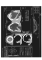
- FIG. 4 is a diagram illustrating an example of a processing result by the volume data processing unit 319 according to the first embodiment.
- the volume data processing unit 319 can generate a superimposed image in which a singular region is superimposed on a Polar-map image by a “time phase maintaining display method”.
- “ant-sept” shown in FIG. 4 is a front wall septum
- “ant” is a front wall
- “lat” is a side wall
- post” is a rear wall
- Inf is the lower wall
- septum is the septum.
- the volume data processing unit 319 changes the time change of the electrocardiogram waveform and the average motion information (average area change rate) for every 16 fractions, together with the time-keeping type superimposed image.
- a curve graph can also be synthesized.
- the time change curve of the average area change rate of each of the 16 fractions is shown by a solid line.
- the volume data processing unit 319 can determine which fraction the time variation curve of each average motion information corresponds to, and the time variation curve of the average motion information of each of the 16 fractions. Is colored with the tone assigned to each fraction.
- the volume data processing unit 319 generates a plurality of MPR images having a short-axis cross section or a long-axis cross section from the volume data.
- the volume data processing unit 319 generates a composite image in which an image in which a specific region is superimposed on the left ventricular heart wall of the apex four-chamber image in the region A is arranged in a time-phase-holding manner. is doing.
- the volume data processing unit 319 has a composite image in which an image in which a specific region is superimposed on the left ventricular heart wall of the apex two-chamber image in the region B is arranged in a time-phase-holding type. Is generated. *
- the volume data processing unit 319 arranges an image in which a singular region is superimposed on the left ventricular heart wall of a short-axis cross-sectional image close to the apex in the region C3 in a time-keeping manner.
- the synthesized image is generated.
- the volume data processing unit 319 has a temporal region holding type on the left ventricular heart wall of the short-axis cross-sectional image located in the middle between the apex and the base in the region C5.
- a composite image is generated in which the images superposed in (1) are arranged.
- the volume data processing unit 319 arranges an image in which a singular region is superimposed on the left ventricular heart wall of a short-axis cross-sectional image close to the base in a time-keeping type in the region C7.
- the synthesized image is generated.
- the EDV shown in FIG. 4 is the volume of the heart lumen in the end diastole (ED) phase. In the example illustrated in FIG. 4, the EDV is “156.01 mL” and the end diastole (reference time phase) time is “0 msec”.
- the ESV shown in FIG. 4 is the volume of the heart lumen in the end systole (ES) phase. In the example shown in FIG. 4, the ESV is “109.20 mL” and the end systolic time is “422 msec”. *
- EF shown in FIG. 4 is an ejection ratio defined by EDV and ESV. In the example illustrated in FIG. 4, the EF is “30.01%”.
- “1.05 ⁇ MV” shown in FIG. 4 is obtained by multiplying the myocardial volume (MV) by “1.05 g / mL” which is an average myocardial density value. It is.
- “1.05 ⁇ MV” is “140.66 g”.
- “est.LV MASS” indicating that “140.66 g” is estimated from the myocardial volume of the left ventricle is shown.
- the volume data processing unit 319 may calculate a time change rate (Area change rate) of a local area change rate (Area change) as exercise information. That is, the volume data processing unit 319 may calculate the time change rate of the area change rate by estimating the time differential value of the local area change rate. In such a case, as shown in FIG. 5A, the volume data processing unit 319 changes the color tone of the superimposed image so as to assign a color at each time when the threshold value is reached, with a predetermined value as a threshold value.
- FIG. 5A is a diagram for explaining an example of processing by the volume data processing unit 319 according to the first embodiment.
- FIG. 5B is a diagram illustrating an example of an image generated by the volume data processing unit 319 according to the first embodiment.
- FIG. 5B shows an image in which the state of excitation propagation in the heart is depicted.
- NOMAL health
- CLBBB complete left leg block
- a superimposed image in which the color tone is superimposed on the surface rendering image and a superimposed image in which the color tone is superimposed on the Polar-map image It shows.
- CLBBB an asynchronous part (Latest Site) is shown.
- an asynchronous part is identified from the superimposed image shown in FIG. 5B, and an X-ray image using a contrast agent is referred to and an electrode (pacing lead) is placed in the vein closest to the asynchronous part.
- an electrode pacing lead
- the electrode is accurately placed by further superimposing and displaying the superimposed image of the ultrasonic wave on the asynchronous part in the X-ray image.
- the X-ray image and the ultrasonic image to be superimposed are a moving image or a still image, respectively.
- the image processing apparatus 100 combines an X-ray image and an ultrasonic image to be superimposed in a combination of a moving image and a moving image, a combination of a moving image and a still image, or a still image and a moving image according to a display state.
- By superimposing the image in combination with the image it is possible to display an image with high visibility in the superimposed image of the X-ray image and the ultrasonic image.
- the superimposed image of the X-ray image and the ultrasonic image is referred to as a fusion image.
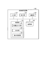
- FIG. 6 is a diagram illustrating an example of the configuration of the image processing apparatus 100 according to the first embodiment.
- the image processing apparatus 100 includes an input unit 110, a display unit 120, a communication unit 130, a storage unit 140, and a control unit 150.
- the image processing apparatus 100 is a workstation, an arbitrary personal computer, or the like, and is connected to the X-ray diagnostic apparatus 200, the ultrasonic diagnostic apparatus 300, the image storage apparatus 400, and the like via a network.
- the input unit 110 is a mouse, a keyboard, a trackball, or the like, and receives input of various operations on the image processing apparatus 100 from an operator (for example, an interpreting doctor). Specifically, the input unit 110 receives input of information for acquiring an X-ray image or an ultrasonic image.
- the display unit 120 is a liquid crystal panel or the like as a monitor, and displays various information. Specifically, the display unit 120 displays a GUI (Graphical User Interface) for receiving various operations from the operator, and a superimposed image of an X-ray image and an ultrasonic image that are processing results by the control unit 150 described later. To do.
- the communication unit 130 is a NIC (Network Interface Card) or the like, and communicates with other devices.
- the storage unit 140 is, for example, a semiconductor memory device such as a RAM (Random Access Memory) or a flash memory, or a storage device such as a hard disk or an optical disk, and stores an X-ray image, an ultrasonic image, or the like. To do.
- a semiconductor memory device such as a RAM (Random Access Memory) or a flash memory
- a storage device such as a hard disk or an optical disk
- the control unit 150 is, for example, an electronic circuit such as a CPU (Central Processing Unit) or MPU (Micro Processing Unit), an integrated circuit such as an ASIC (Application Specific Integrated Circuit) or FPGA (Field Programmable Gate Array), and an image processing apparatus. 100 total control is performed.
- a CPU Central Processing Unit
- MPU Micro Processing Unit
- ASIC Application Specific Integrated Circuit
- FPGA Field Programmable Gate Array
- control unit 150 includes, for example, an alignment unit 151, a determination unit 152, and a display control unit 153, and by changing the combination of fusion images according to the display status, A fusion image with high visibility is displayed.
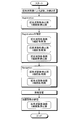
- FIG. 7 is a diagram for explaining an example of a fusion image display state according to the first embodiment.
- FIG. 7 shows a CRT procedure workflow.
- an ultrasonic image of the heart is acquired by the ultrasonic diagnostic apparatus 300, and a diagnosis and treatment plan are made.
- registration for registration at an accurate position is performed.
- the fusion image at this time is, for example, as shown in FIG. 7 in which a still image X-ray image is superimposed on a still image ultrasound image.
- the fusion image is generated as a combination of an ultrasonic image and an X-ray image as a moving image and a moving image, a still image and a moving image, or a moving image and a still image. This is because the X-ray image is moved while the ultrasonic image is still image, the ultrasonic image is moved while the X-ray image is still image, or both are moved. It is confirmed whether or not.
- the doctor carries the electrode (Navigation) to the blood vessel closest to the asynchronous part while viewing the fusion image, and the electrode is placed.
- the X-ray image is a moving image
- the ultrasonic image is a moving image or a still image.
- the therapeutic effect is confirmed.
- the ultrasonic image is a moving image
- the X-ray image is a still image.
- the control unit 150 determines a combination of fusion images according to each display state illustrated in FIG. 7 and causes the display unit 120 to display the fusion image of the determined combination.
- the display state shown in FIG. 7 is merely an example.
- the embodiment is not limited to displaying a fusion image related to a CRT procedure.
- the combination of fusion images shown in FIG. 7 is also an example, and the present invention is not limited to this.
- a fusion image in which a moving image ultrasound image is superimposed on a moving image X-ray image may be used.
- a combination of these display states and fusion images can be arbitrarily determined by an observer such as a doctor.
- the alignment unit 151 executes alignment when the X-ray image and the second image are superimposed.
- the alignment unit 151 performs alignment when superimposing the X-ray image and the second image.
- the alignment unit 151 may be configured such that an X-ray coordinate system that is a coordinate in a space where an X-ray image is captured and an ultrasonic coordinate system that is a coordinate in a space where an ultrasonic image is captured. Associate each coordinate system from the positional relationship.
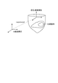
- FIG. 8 is a diagram for explaining an example of processing by the alignment unit 151 according to the first embodiment.
- the alignment unit 151 identifies the position of the ultrasonic coordinate system in the X-ray coordinate system as shown in FIG. That is, the alignment unit 151 specifies where in the X-ray coordinate system the coordinate space in which the ultrasound images are collected corresponds.
- examples of the alignment method by the alignment unit 151 include the following three methods.
- the first method is a method using a position sensor.
- the ultrasonic probe 320 to which the position sensor 352 is attached is photographed by the X-ray diagnostic apparatus 200.
- the alignment unit 151 calculates the coordinates of the ultrasonic probe 320 in the X-ray coordinate system from the position of the ultrasonic probe 320 included in the captured X-ray image. Further, the alignment unit 151 acquires position information of the position sensor 352 when the X-ray image is captured from the ultrasonic diagnostic apparatus 300. That is, the alignment unit 151 acquires the coordinates of the ultrasonic probe 320 in the ultrasonic coordinate system when an X-ray image is captured.
- the alignment unit 151 associates the coordinates of the ultrasonic probe 320 in the X-ray coordinate system with the coordinates of the ultrasonic probe 320 in the ultrasonic coordinate system when the X-ray image is captured, thereby allowing the X-ray coordinate system to Specify the position of the ultrasonic coordinate system. Thereby, the alignment part 151 can calculate the coordinate in the X-ray coordinate system of the treatment location specified in the ultrasonic image.
- the second method is a method using landmarks.
- the observer sets a portion that can be confirmed in the X-ray image as a landmark on the ultrasonic image.
- the alignment unit 151 aligns the ultrasonic image and the X-ray image using the landmark set in the ultrasonic image and the position corresponding to the landmark on the X-ray image. For example, a ventricular wall in an ultrasonic image is set as a landmark.
- the alignment unit 151 aligns the X-ray coordinate system and the ultrasonic coordinate system using the contrasted X-ray image and the ultrasonic image in which the landmark is set.
- a CT image is used.
- the alignment unit 151 specifies the position of the ultrasonic coordinate system in the CT coordinate system by aligning the ultrasonic image and the CT image. Further, the alignment unit 151 specifies the position of the X-ray coordinate system in the CT coordinate system by aligning the X-ray image and the CT image. Then, the alignment unit 151 specifies the position of the ultrasonic coordinate system in the X-ray coordinate system from the position of the ultrasonic coordinate system in the CT coordinate system and the position of the X-ray coordinate system in the CT coordinate system.
- the alignment unit 151 accurately calculates where in the X-ray image the treatment site specified in the ultrasonic image corresponds by specifying the position of the ultrasonic coordinate system in the X-ray coordinate system. This makes it possible to generate a fusion image superimposed at an accurate position.
- the alignment method described above is merely an example, and the embodiment is not limited to this. That is, any method may be used as long as it can identify the position of the ultrasonic coordinate system in the X-ray coordinate system.
- the determination unit 152 determines whether to display the X-ray image and the second image, which are the first images, as moving images or still images based on the display status. Decide each. For example, the determination unit 152 determines the combination of the fusion image of the X-ray image and the ultrasonic image along the workflow shown in FIG.
- the determination unit 152 can determine a more detailed combination as a combination of fusion images in addition to a combination of a moving image and a still image.
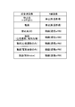
- FIG. 9 is a diagram illustrating an example of a combination of fusion images determined by the determination unit 152 according to the first embodiment.
- the determination unit 152 determines a still image (+ frame advance) and a still image (contrast image) as a combination of an ultrasonic image and an X-ray image.
- a still image (+ frame advance)
- a still image (contrast image)
- the ultrasonic image is a still image in which alignment information such as landmarks is expressed.
- the ultrasonic image may be an image capable of frame advance.
- the determination unit 152 determines a moving image and a still image (contrast image) as a combination of an ultrasonic image and an X-ray image. Such a combination is set to be used mainly when confirming the alignment.
- the X-ray image is a still image in which blood vessels are contrasted
- the ultrasonic image is a moving image in which alignment information such as landmarks is expressed.
- the determination unit 152 determines a still image (AI: Activation Imaging) and a moving image (perspective or RM: Road Map) as a combination of an ultrasonic image and an X-ray image.
- a still image AI: Activation Imaging
- a moving image perspective or RM: Road Map
- the X-ray image is a fluoroscopic moving image that can guide in real time that the electrode is moving
- the ultrasonic image is a still image in which the electrode placement planned position is clearly shown.
- the X-ray image can be a road map image in which blood vessels are mask images.
- the blood vessel mask image in the road map image may be a still image or a moving image.
- the determination unit 152 determines a moving image (heartbeat motion, electrical conduction) and a moving image (transmission or RM) as a combination of an ultrasonic image and an X-ray image.
- a moving image heartbeat motion, electrical conduction
- a moving image transmission or RM
- the X-ray image is a fluoroscopic video that can guide in real time that the electrode is moving
- the ultrasonic image is a video (color-mapped) that clearly shows the planned electrode placement and expresses the movement and electrical conduction of the heart. Moving video).
- the X-ray image can be a road map image in which blood vessels are mask images.
- the blood vessel mask image in the road map image may be a still image or a moving image.
- the determination unit 152 determines a moving image (only a heartbeat motion) and a moving image (perspective or RM) as a combination of an ultrasonic image and an X-ray image.
- a moving image is a fluoroscopic moving image that can guide in real time that the electrode is moving
- the ultrasonic image is a moving image that clearly shows the electrode placement planned position and expresses the motion of the heart.
- the X-ray image can be a road map image in which blood vessels are mask images.
- the blood vessel mask image in the road map image may be a still image or a moving image.
- the determination unit 152 determines a moving image (electric conduction only) and a moving image (perspective or RM) as a combination of an ultrasonic image and an X-ray image.
- a moving image electric conduction only
- a moving image moving image
- RM moving image
- Such a combination is set to be used, for example, when carrying an electrode.
- the X-ray image is a fluoroscopic moving image that can guide in real time that the electrode is moving
- the ultrasonic image is a moving image that clearly shows the electrode placement planned position and expresses only electric conduction. That is, the ultrasonic image is not deformed by the heartbeat motion, and only the color map changes. Thereby, the heartbeat motion is expressed only by the X-ray image, and an image with high visibility can be displayed.
- the X-ray image can be a road map image in which blood vessels are mask images.
- the blood vessel mask image in the road map image may be a still image or a moving image.
- the determination unit 152 determines a moving image (another window) and a moving image (perspective or RM) as a combination of an ultrasonic image and an X-ray image.
- a moving image is set to be used, for example, when carrying an electrode.
- the X-ray image is a fluoroscopic moving image that can guide in real time that the electrode is moving, and a still image ultrasonic image in which the electrode placement planned position is clearly shown is superimposed.
- a moving image in which electrical conduction is expressed in another window is displayed.
- an image of a different format such as a Polar Map image may be displayed, or a 2D ultrasonic image may be displayed as a moving image.
- the display control unit 153 converts the X-ray image and the ultrasonic image into a combination of a moving image and a moving image, a combination of a moving image and a still image, or a still image based on the determination by the determining unit 152. Control is performed so that at least one of the superimposed image superimposed by any one of the combination of the image and the moving image and the parallel image paralleled by any one of the combination is displayed on the display unit 120. Specifically, the display control unit 153 causes the display unit 120 to display the combination fusion image determined by the determination unit 152. Note that the display control unit 153 causes the display unit 120 to display the fusion image that has been aligned by the alignment unit 151.
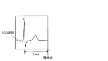
- the display control unit 153 when the superimposed image includes a moving image, the display control unit 153 superimposes the X-ray image and the ultrasonic image in synchronism with each other. More specifically, when using an X-ray image collected in real time for a superimposed image including a moving image, the display control unit 153 calculates a time from the immediately preceding R wave to the current time in the electrocardiogram signal of the subject, In the ultrasonic image, an ultrasonic image frame having a phase after the time calculated from the R wave is superimposed on the current X-ray image frame.
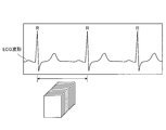
- FIG. 10A is a diagram for explaining an ultrasonic image used by the display control unit 153 according to the first embodiment.
- FIG. 10B is a diagram for explaining an X-ray image used for real-time display by the display control unit 153 according to the first embodiment.
- the display control unit 153 extracts a frame having substantially the same phase as that of the current X-ray image from the ultrasonic image frames collected within the RR interval of the ECG waveform. Then, it is superimposed on the X-ray image.
- the display control unit 153 acquires the phase corresponding to the current frame of the X-ray image captured in real time from the ECG waveform. That is, as shown in FIG. 10B, the display control unit 153 calculates the time “t sec” from the current time to the immediately preceding R wave.
- the display control unit 153 determines the phase at the time when “t sec” has elapsed from the R wave in the frame of the ultrasonic image as the phase substantially the same as the current phase of the X-ray image. Then, the display control unit 153 extracts a frame corresponding to the determined phase from the ultrasonic image frames, and superimposes the extracted ultrasonic image frame on the current frame in the X-ray image frame. The image is displayed on the display unit. Note that the display control unit 153 displays the fusion image in a state of being aligned by the alignment unit 151. In addition, when the X-ray image is captured in real time, the display control unit 153 determines the phase of the ultrasonic image frame that is substantially the same as the current phase each time an R wave appears in the ECG waveform.
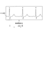
- the display control unit 153 calculates the phase of the X-ray image frame at the RR interval of the electrocardiogram signal of the subject, extracts an ultrasound image frame having substantially the same phase as the calculated phase, and extracts the extracted ultrasound image frame Is superimposed on the X-ray image frame.
- FIG. 10C is a diagram for explaining an ultrasonic image used by the display control unit 153 according to the first embodiment.
- FIG. 10C is a diagram for explaining an X-ray image used for display after X-ray image capturing is completed.
- the display control unit 153 calculates where in the X-ray image frame the frame at the start of the moving image is located in the RR interval, and exceeds the position that is substantially the same as the calculated position.
- the frame of the sound wave image is extracted and the fusion image is displayed.
- the display control unit 153 sets a ratio “a: b” between the moving image start time to the immediately preceding R wave and the moving image start time to the immediately following R in the RR interval. calculate.
- the display control unit 153 extracts a frame having a phase of “a: b” at the RR interval in the ultrasonic image.
- the display control unit 153 causes the display unit 120 to display a fusion image in which the extracted ultrasonic image frame is superimposed on the X-ray image frame at the start of the moving image.
- the display control unit 153 includes an X-ray image frame and an ultrasonic image that have substantially the same phase based on an area corresponding to the landmark in the X-ray image and the landmark added to the ultrasonic image. A frame is extracted, and the extracted X-ray image frame and ultrasonic image frame are superimposed. Specifically, when alignment by a landmark is executed by the alignment unit 151, the display control unit 153 synchronizes the phase using the landmark. For example, the display control unit 153 extracts a frame having substantially the same phase as the phase of the frame at the start of the moving image from the frame of the ultrasonic image based on the position and shape of the landmark. Then, the display control unit 153 causes the display unit 120 to display a fusion image in which the extracted ultrasonic image frame is superimposed on the X-ray image frame at the start of the moving image.
- FIG. 11 is a diagram illustrating an example of display control processing by the display control unit 153 according to the first embodiment.
- the display control unit 153 causes the display unit 120 to display a fusion image in which the ultrasound image 20 (a superimposed image in which a color tone is superimposed on the surface rendering image) is superimposed on the X-ray image 10.
- the display control unit 153 displays each image as a moving image or a still image, and in the case of a moving image, displays a fusion image in which the phases of the images are synchronized.
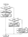
- FIG. 12 is a flowchart illustrating a processing procedure performed by the image processing apparatus 100 according to the first embodiment.
- FIG. 13 is a flowchart illustrating a procedure of synchronization processing performed by the image processing apparatus 100 according to the first embodiment.
- FIG. 12 shows the process after the alignment process by the alignment unit 151 is completed.
- FIG. 13 shows details of the process in step S103 of FIG.
- the determination unit 152 acquires a display situation (step S101) and determines whether or not to superimpose a moving image based on the display situation. Determination is made (step S102).
- the display control unit 153 synchronizes the phase (Step S103) and superimposes an ultrasonic image on the X-ray image (Step S104).
- Step S104 the display control unit 153 superimposes the ultrasonic image on the X-ray image. Then, the display control unit 153 causes the display unit 120 to display a fusion image obtained by superimposing an ultrasonic image on the X-ray image (step S105), and ends the process.
- step S ⁇ b> 201 when synchronizing the phases, the display control unit 153 determines whether or not the display is in real time.
- the display control unit 153 calculates the time from the R wave immediately before the current time to the current time (Step S202), and exceeds the phase corresponding to the calculated time.
- a frame of the sound image is extracted (step S203).
- Step S204 determines whether or not to use an electrocardiogram.
- the display control unit 153 calculates the phase of the frame of the X-ray image at the RR interval, and extracts the frame of the ultrasonic image having substantially the same phase as the calculated phase. (Step S205).
- step S204 when an electrocardiogram is not used in step S204 (No in step S204), the display control unit 153 displays an ultrasonic image including a landmark that is substantially the same as the position and shape of the landmark in the frame of the X-ray image. A frame is extracted (step S206).
- the determination unit 152 displays the X-ray image that is the first image and the second image as either a moving image or a still image based on the display state. Decide each. Based on the determination by the determination unit 152, the display control unit 153 converts the X-ray image and the second image into a combination of a moving image and a moving image, a combination of a moving image and a still image, or a still image and a moving image. Control is performed so that the fusion image superimposed in any combination with the image is displayed on the display unit 120. Therefore, the image processing apparatus 100 according to the first embodiment can display a fusion image according to the display status, and displays an image with high visibility in a superimposed image of an X-ray image and another medical image. Make it possible.
- the display control unit 153 when the fusion image includes a moving image, the display control unit 153 superimposes the phases of the X-ray image and the ultrasonic image in synchronization. Therefore, the image processing apparatus 100 according to the first embodiment can display an image with high visibility even in a procedure using a moving image.
- the display control unit 153 when using an X-ray image collected in real time as a fusion image including a moving image, the display control unit 153 includes the R wave from the previous R wave to the current time in the electrocardiogram signal of the subject. Time is calculated, and an ultrasonic image frame having a phase after the time calculated from the R wave in the ultrasonic image is superimposed on the current X-ray image frame. Therefore, the image processing apparatus 100 according to the first embodiment makes it possible to perform phase synchronization of an arrhythmia patient that is difficult to synchronize with simple electrocardiographic synchronization.
- the display control unit 153 calculates the phase of the X-ray image frame at the RR interval of the electrocardiogram signal of the subject, and outputs an ultrasound image frame having substantially the same phase as the calculated phase.
- the extracted ultrasonic image frame is superimposed on the X-ray image frame. Therefore, the image processing apparatus 100 according to the first embodiment makes it possible to easily perform phase synchronization.
- the display control unit 153 has substantially the same phase based on the landmark given to the ultrasonic image and the region corresponding to the landmark in the X-ray image. X-ray image frames and ultrasonic image frames are extracted, and the extracted X-ray image frames and ultrasonic image frames are superimposed. Therefore, the image processing apparatus 100 according to the first embodiment makes it possible to synchronize the phases without acquiring an electrocardiographic waveform.
- the display control unit 153 reflects only the color change in the fusion image when the ultrasonic image is color-mapped. Therefore, the image processing apparatus 100 according to the first embodiment makes it possible to suppress a decrease in visibility due to a superimposed moving image.
- the image processing apparatus 100 may include the X-ray image and the X-ray image. It is possible to display an ultrasonic image in parallel, or to display a fusion image and an ultrasonic image in parallel.
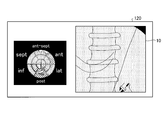
- 14A and 14B are diagrams illustrating an example of display control processing by the display control unit according to the second embodiment.
- FIG. 14A shows an example of a parallel image of an X-ray image and an ultrasonic image.
- FIG. 14B shows an example of a parallel image of a fusion image and an ultrasonic image.
- the display control unit 153 according to the second embodiment, as shown in FIG. 14A, a Polar Map image (moving image ultrasound image) in which a moving X-ray image 10 and a specific region are superimposed in a time-phase-holding type. ) are displayed in parallel in separate windows.
- the display control unit 153 displays the two moving images in synchronization with each other. That is, the display control unit 153 displays the two moving images in synchronization with each other using, for example, an ECG waveform in the same manner as the synchronization method described above.
- the display control unit 153 includes a fusion image obtained by superimposing an ultrasonic image 20 (a superimposed image obtained by superimposing a color tone on a surface rendering image) on the X-ray image 10 of a moving image, and a unique region.
- Polar Map image moving ultrasound image
- the display control unit 153 displays the phases of the fusion image and the Polar Map image in synchronization.
- an ultrasonic image is used as the second image.
- the embodiment is not limited to this.
- a CT Computerized Tomography
- an MR Magnetic Resonance
- PET Positron Emission Tomography
- IVAS Intravascular Ultrasound
- ICE Intra Cardiac Echo
- EM Electro anatomical Mapping
- the image processing apparatus 100 can display an X-ray image and an ultrasonic image in parallel in separate windows, and in addition to the fusion image, additional information such as a Polar Map image. Can be further provided to the observer.
- the X-ray diagnostic apparatus 200 may include the image processing apparatus 100 described above. That is, the system control unit 221 of the X-ray diagnostic apparatus 200 may include the above-described alignment unit 151, determination unit 152, and display control unit 153, and execute the above-described processing.
- the image processing apparatus of at least one embodiment described above it is possible to display an image with high visibility in a superimposed image of an X-ray image and another medical image.
Landscapes
- Health & Medical Sciences (AREA)
- Life Sciences & Earth Sciences (AREA)
- Engineering & Computer Science (AREA)
- Medical Informatics (AREA)
- Public Health (AREA)
- Physics & Mathematics (AREA)
- Biomedical Technology (AREA)
- Pathology (AREA)
- General Health & Medical Sciences (AREA)
- Biophysics (AREA)
- Nuclear Medicine, Radiotherapy & Molecular Imaging (AREA)
- Veterinary Medicine (AREA)
- Radiology & Medical Imaging (AREA)
- Heart & Thoracic Surgery (AREA)
- Molecular Biology (AREA)
- Surgery (AREA)
- Animal Behavior & Ethology (AREA)
- Optics & Photonics (AREA)
- High Energy & Nuclear Physics (AREA)
- Computer Vision & Pattern Recognition (AREA)
- Human Computer Interaction (AREA)
- Physiology (AREA)
- Cardiology (AREA)
- Computer Graphics (AREA)
- General Engineering & Computer Science (AREA)
- Dentistry (AREA)
- Oral & Maxillofacial Surgery (AREA)
- General Physics & Mathematics (AREA)
- Theoretical Computer Science (AREA)
- Epidemiology (AREA)
- Primary Health Care (AREA)
- Databases & Information Systems (AREA)
- Data Mining & Analysis (AREA)
- Ultra Sonic Daignosis Equipment (AREA)
- Apparatus For Radiation Diagnosis (AREA)
- Electrotherapy Devices (AREA)
Priority Applications (2)
| Application Number | Priority Date | Filing Date | Title |
|---|---|---|---|
| CN201380049235.3A CN104661596B (zh) | 2012-09-20 | 2013-09-20 | 图像处理装置、x射线诊断装置以及显示方法 |
| US14/642,808 US9931090B2 (en) | 2012-09-20 | 2015-03-10 | Image processing apparatus, X-ray diagnosis apparatus, and display method |
Applications Claiming Priority (2)
| Application Number | Priority Date | Filing Date | Title |
|---|---|---|---|
| JP2012-207496 | 2012-09-20 | ||
| JP2012207496A JP6109512B2 (ja) | 2012-09-20 | 2012-09-20 | 画像処理装置、x線診断装置及びプログラム |
Related Child Applications (1)
| Application Number | Title | Priority Date | Filing Date |
|---|---|---|---|
| US14/642,808 Continuation US9931090B2 (en) | 2012-09-20 | 2015-03-10 | Image processing apparatus, X-ray diagnosis apparatus, and display method |
Publications (1)
| Publication Number | Publication Date |
|---|---|
| WO2014046263A1 true WO2014046263A1 (ja) | 2014-03-27 |
Family
ID=50341562
Family Applications (1)
| Application Number | Title | Priority Date | Filing Date |
|---|---|---|---|
| PCT/JP2013/075572 Ceased WO2014046263A1 (ja) | 2012-09-20 | 2013-09-20 | 画像処理装置、x線診断装置及び表示方法 |
Country Status (4)
| Country | Link |
|---|---|
| US (1) | US9931090B2 (enExample) |
| JP (1) | JP6109512B2 (enExample) |
| CN (1) | CN104661596B (enExample) |
| WO (1) | WO2014046263A1 (enExample) |
Cited By (1)
| Publication number | Priority date | Publication date | Assignee | Title |
|---|---|---|---|---|
| EP3017766A1 (en) * | 2014-11-07 | 2016-05-11 | Samsung Medison Co., Ltd. | Ultrasound imaging apparatus and control method thereof |
Families Citing this family (15)
| Publication number | Priority date | Publication date | Assignee | Title |
|---|---|---|---|---|
| JP6441015B2 (ja) * | 2014-10-06 | 2018-12-19 | キヤノンメディカルシステムズ株式会社 | X線診断装置及びx線管制御方法 |
| EP3203440A1 (en) * | 2016-02-08 | 2017-08-09 | Nokia Technologies Oy | A method, apparatus and computer program for obtaining images |
| JP7080590B2 (ja) * | 2016-07-19 | 2022-06-06 | キヤノンメディカルシステムズ株式会社 | 医用処理装置、超音波診断装置、および医用処理プログラム |
| JP6740051B2 (ja) * | 2016-07-26 | 2020-08-12 | キヤノンメディカルシステムズ株式会社 | 超音波診断装置、医用画像処理装置及び医用画像処理プログラム |
| EP3629882A4 (en) * | 2017-05-24 | 2021-05-19 | Body Vision Medical Ltd. | METHODS OF USING RADIAL ENDOBRONCHIC ULTRASONIC PROBES FOR THREE-DIMENSIONAL IMAGE RECONSTRUCTION AND IMPROVED TARGET LOCATION |
| US11217344B2 (en) * | 2017-06-23 | 2022-01-04 | Abiomed, Inc. | Systems and methods for capturing data from a medical device |
| US11138746B2 (en) | 2017-07-03 | 2021-10-05 | Ricoh Company, Ltd. | Diagnostic support system and diagnostic support method |
| JP7120560B2 (ja) * | 2017-07-03 | 2022-08-17 | 株式会社リコー | 診断支援システム、診断支援方法及び診断支援プログラム |
| JP2021503364A (ja) * | 2017-11-16 | 2021-02-12 | エバメッド・エセアー | 心臓不整脈非侵襲的治療装置及び方法 |
| JP7032157B2 (ja) * | 2018-02-02 | 2022-03-08 | キヤノンメディカルシステムズ株式会社 | 医用画像診断装置及びx線照射制御装置 |
| JP7258483B2 (ja) * | 2018-07-05 | 2023-04-17 | キヤノンメディカルシステムズ株式会社 | 医用情報処理システム、医用情報処理装置及び超音波診断装置 |
| CN111727013B (zh) * | 2018-10-24 | 2023-12-22 | 中国医学科学院北京协和医院 | 一种成像方法以及成像系统 |
| US12343529B2 (en) | 2020-03-31 | 2025-07-01 | Novocure Gmbh | Methods, systems, and apparatuses for guiding transducer placements for tumor treating fields |
| JP7514673B2 (ja) * | 2020-07-01 | 2024-07-11 | キヤノンメディカルシステムズ株式会社 | 医用画像処理装置及び医用画像処理システム |
| US12251263B2 (en) * | 2022-06-02 | 2025-03-18 | Canon U.S.A., Inc. | Devices, systems, and methods for automated delay detection between medical-imaging devices |
Citations (3)
| Publication number | Priority date | Publication date | Assignee | Title |
|---|---|---|---|---|
| JP2009160307A (ja) * | 2008-01-09 | 2009-07-23 | Toshiba Corp | 放射線治療システム、放射線治療支援装置及び放射線治療支援プログラム |
| JP2009247739A (ja) * | 2008-04-09 | 2009-10-29 | Toshiba Corp | 医用画像処理表示装置、そのコンピュータ処理プログラム及び超音波診断装置。 |
| JP2012045285A (ja) * | 2010-08-30 | 2012-03-08 | Ge Medical Systems Global Technology Co Llc | 超音波診断装置及びその制御プログラム |
Family Cites Families (7)
| Publication number | Priority date | Publication date | Assignee | Title |
|---|---|---|---|---|
| JP5052123B2 (ja) * | 2006-12-27 | 2012-10-17 | 富士フイルム株式会社 | 医用撮像システム及び方法 |
| JP5238201B2 (ja) | 2007-08-10 | 2013-07-17 | 株式会社東芝 | 超音波診断装置、超音波画像処理装置及び超音波画像処理プログラム |
| US8238516B2 (en) | 2008-01-09 | 2012-08-07 | Kabushiki Kaisha Toshiba | Radiotherapy support apparatus |
| EP2160978A1 (en) * | 2008-09-05 | 2010-03-10 | General Electric Company | Method and apparatus for catheter guidance using a combination of ultrasound and x-ray imaging |
| WO2010051037A1 (en) * | 2008-11-03 | 2010-05-06 | Bruce Reiner | Visually directed human-computer interaction for medical applications |
| JP5846755B2 (ja) * | 2010-05-14 | 2016-01-20 | 株式会社東芝 | 画像診断装置及び医用画像表示装置 |
| EP2596750A4 (en) * | 2011-06-30 | 2013-09-25 | Kanzaki Clinic Of Cardiovascular Medicine Medical Corp | X-RAY DIAGNOSTIC DEVICE |
-
2012
- 2012-09-20 JP JP2012207496A patent/JP6109512B2/ja active Active
-
2013
- 2013-09-20 CN CN201380049235.3A patent/CN104661596B/zh active Active
- 2013-09-20 WO PCT/JP2013/075572 patent/WO2014046263A1/ja not_active Ceased
-
2015
- 2015-03-10 US US14/642,808 patent/US9931090B2/en active Active
Patent Citations (3)
| Publication number | Priority date | Publication date | Assignee | Title |
|---|---|---|---|---|
| JP2009160307A (ja) * | 2008-01-09 | 2009-07-23 | Toshiba Corp | 放射線治療システム、放射線治療支援装置及び放射線治療支援プログラム |
| JP2009247739A (ja) * | 2008-04-09 | 2009-10-29 | Toshiba Corp | 医用画像処理表示装置、そのコンピュータ処理プログラム及び超音波診断装置。 |
| JP2012045285A (ja) * | 2010-08-30 | 2012-03-08 | Ge Medical Systems Global Technology Co Llc | 超音波診断装置及びその制御プログラム |
Cited By (1)
| Publication number | Priority date | Publication date | Assignee | Title |
|---|---|---|---|---|
| EP3017766A1 (en) * | 2014-11-07 | 2016-05-11 | Samsung Medison Co., Ltd. | Ultrasound imaging apparatus and control method thereof |
Also Published As
| Publication number | Publication date |
|---|---|
| JP6109512B2 (ja) | 2017-04-05 |
| CN104661596B (zh) | 2017-12-08 |
| US20150173698A1 (en) | 2015-06-25 |
| JP2014061093A (ja) | 2014-04-10 |
| US9931090B2 (en) | 2018-04-03 |
| CN104661596A (zh) | 2015-05-27 |
Similar Documents
| Publication | Publication Date | Title |
|---|---|---|
| JP6109512B2 (ja) | 画像処理装置、x線診断装置及びプログラム | |
| JP6207819B2 (ja) | 画像処理装置、x線診断装置及びプログラム | |
| US11191524B2 (en) | Ultrasonic diagnostic apparatus and non-transitory computer readable medium | |
| CN105662475B (zh) | 超声波诊断装置、图像处理装置以及图像处理方法 | |
| US9865082B2 (en) | Image processing system, X-ray diagnostic apparatus, and image processing method | |
| JP6202963B2 (ja) | 画像処理システム、x線診断装置及び画像処理方法 | |
| JP5586203B2 (ja) | 超音波診断装置、超音波画像処理装置及び超音波画像処理プログラム | |
| JP5619584B2 (ja) | 超音波診断装置、超音波画像処理装置及び超音波画像処理プログラム | |
| JP6222797B2 (ja) | X線診断装置及びプログラム | |
| JP2018191848A (ja) | X線診断装置および医用画像診断システム | |
| JP7271126B2 (ja) | 超音波診断装置及び医用画像処理装置 | |
| JP2022012486A (ja) | 医用画像処理装置及び医用画像処理システム | |
| WO2009156894A1 (en) | Method and system for cardiac resynchronization therapy |
Legal Events
| Date | Code | Title | Description |
|---|---|---|---|
| 121 | Ep: the epo has been informed by wipo that ep was designated in this application |
Ref document number: 13838352 Country of ref document: EP Kind code of ref document: A1 |
|
| NENP | Non-entry into the national phase |
Ref country code: DE |
|
| 122 | Ep: pct application non-entry in european phase |
Ref document number: 13838352 Country of ref document: EP Kind code of ref document: A1 |