WO2014045858A1 - 手押し車 - Google Patents
手押し車 Download PDFInfo
- Publication number
- WO2014045858A1 WO2014045858A1 PCT/JP2013/073608 JP2013073608W WO2014045858A1 WO 2014045858 A1 WO2014045858 A1 WO 2014045858A1 JP 2013073608 W JP2013073608 W JP 2013073608W WO 2014045858 A1 WO2014045858 A1 WO 2014045858A1
- Authority
- WO
- WIPO (PCT)
- Prior art keywords
- unit
- main body
- wheel
- control mode
- angle
- Prior art date
- Legal status (The legal status is an assumption and is not a legal conclusion. Google has not performed a legal analysis and makes no representation as to the accuracy of the status listed.)
- Ceased
Links
Images









Classifications
-
- A—HUMAN NECESSITIES
- A61—MEDICAL OR VETERINARY SCIENCE; HYGIENE
- A61H—PHYSICAL THERAPY APPARATUS, e.g. DEVICES FOR LOCATING OR STIMULATING REFLEX POINTS IN THE BODY; ARTIFICIAL RESPIRATION; MASSAGE; BATHING DEVICES FOR SPECIAL THERAPEUTIC OR HYGIENIC PURPOSES OR SPECIFIC PARTS OF THE BODY
- A61H3/00—Appliances for aiding patients or disabled persons to walk about
- A61H3/04—Wheeled walking aids for patients or disabled persons
-
- A—HUMAN NECESSITIES
- A61—MEDICAL OR VETERINARY SCIENCE; HYGIENE
- A61H—PHYSICAL THERAPY APPARATUS, e.g. DEVICES FOR LOCATING OR STIMULATING REFLEX POINTS IN THE BODY; ARTIFICIAL RESPIRATION; MASSAGE; BATHING DEVICES FOR SPECIAL THERAPEUTIC OR HYGIENIC PURPOSES OR SPECIFIC PARTS OF THE BODY
- A61H3/00—Appliances for aiding patients or disabled persons to walk about
- A61H3/04—Wheeled walking aids for patients or disabled persons
- A61H2003/043—Wheeled walking aids for patients or disabled persons with a drive mechanism
-
- A—HUMAN NECESSITIES
- A61—MEDICAL OR VETERINARY SCIENCE; HYGIENE
- A61H—PHYSICAL THERAPY APPARATUS, e.g. DEVICES FOR LOCATING OR STIMULATING REFLEX POINTS IN THE BODY; ARTIFICIAL RESPIRATION; MASSAGE; BATHING DEVICES FOR SPECIAL THERAPEUTIC OR HYGIENIC PURPOSES OR SPECIFIC PARTS OF THE BODY
- A61H3/00—Appliances for aiding patients or disabled persons to walk about
- A61H3/04—Wheeled walking aids for patients or disabled persons
- A61H2003/046—Wheeled walking aids for patients or disabled persons with braking means
-
- A—HUMAN NECESSITIES
- A61—MEDICAL OR VETERINARY SCIENCE; HYGIENE
- A61H—PHYSICAL THERAPY APPARATUS, e.g. DEVICES FOR LOCATING OR STIMULATING REFLEX POINTS IN THE BODY; ARTIFICIAL RESPIRATION; MASSAGE; BATHING DEVICES FOR SPECIAL THERAPEUTIC OR HYGIENIC PURPOSES OR SPECIFIC PARTS OF THE BODY
- A61H2201/00—Characteristics of apparatus not provided for in the preceding codes
- A61H2201/50—Control means thereof
- A61H2201/5007—Control means thereof computer controlled
-
- A—HUMAN NECESSITIES
- A61—MEDICAL OR VETERINARY SCIENCE; HYGIENE
- A61H—PHYSICAL THERAPY APPARATUS, e.g. DEVICES FOR LOCATING OR STIMULATING REFLEX POINTS IN THE BODY; ARTIFICIAL RESPIRATION; MASSAGE; BATHING DEVICES FOR SPECIAL THERAPEUTIC OR HYGIENIC PURPOSES OR SPECIFIC PARTS OF THE BODY
- A61H2201/00—Characteristics of apparatus not provided for in the preceding codes
- A61H2201/50—Control means thereof
- A61H2201/5023—Interfaces to the user
- A61H2201/5025—Activation means
- A61H2201/5028—Contact activation, i.e. activated at contact with a surface of the user to be treated
-
- A—HUMAN NECESSITIES
- A61—MEDICAL OR VETERINARY SCIENCE; HYGIENE
- A61H—PHYSICAL THERAPY APPARATUS, e.g. DEVICES FOR LOCATING OR STIMULATING REFLEX POINTS IN THE BODY; ARTIFICIAL RESPIRATION; MASSAGE; BATHING DEVICES FOR SPECIAL THERAPEUTIC OR HYGIENIC PURPOSES OR SPECIFIC PARTS OF THE BODY
- A61H2201/00—Characteristics of apparatus not provided for in the preceding codes
- A61H2201/50—Control means thereof
- A61H2201/5058—Sensors or detectors
- A61H2201/5069—Angle sensors
-
- A—HUMAN NECESSITIES
- A61—MEDICAL OR VETERINARY SCIENCE; HYGIENE
- A61H—PHYSICAL THERAPY APPARATUS, e.g. DEVICES FOR LOCATING OR STIMULATING REFLEX POINTS IN THE BODY; ARTIFICIAL RESPIRATION; MASSAGE; BATHING DEVICES FOR SPECIAL THERAPEUTIC OR HYGIENIC PURPOSES OR SPECIFIC PARTS OF THE BODY
- A61H2201/00—Characteristics of apparatus not provided for in the preceding codes
- A61H2201/50—Control means thereof
- A61H2201/5058—Sensors or detectors
- A61H2201/5084—Acceleration sensors
-
- A—HUMAN NECESSITIES
- A61—MEDICAL OR VETERINARY SCIENCE; HYGIENE
- A61H—PHYSICAL THERAPY APPARATUS, e.g. DEVICES FOR LOCATING OR STIMULATING REFLEX POINTS IN THE BODY; ARTIFICIAL RESPIRATION; MASSAGE; BATHING DEVICES FOR SPECIAL THERAPEUTIC OR HYGIENIC PURPOSES OR SPECIFIC PARTS OF THE BODY
- A61H2201/00—Characteristics of apparatus not provided for in the preceding codes
- A61H2201/50—Control means thereof
- A61H2201/5058—Sensors or detectors
- A61H2201/5092—Optical sensor
Definitions
- the present invention relates to a handcart provided with wheels for assisting walking, and more particularly to an electric handcart for driving and controlling the wheels.
- Patent Document 1 describes a walking support device including a mechanism for connecting a self-propelled device and a pedestrian with a handle.
- the walking assist device of Patent Document 1 performs walking assistance / suppression control by motor power in a manner of supporting or pulling a pedestrian with a handle on an uphill and a downhill.
- the walking assist device It is desirable to drive the device that assists walking for a long time.
- the walking assist device is equipped with a large-capacity battery that is driven for a long time, the walking assist device becomes heavy and the manufacturing cost increases.
- the electric wheelbarrow can be easily used as a wheelbarrow without an electric mechanism even when the battery is exhausted.
- an object of the present invention is to provide an electric wheelbarrow capable of controlling a wheel driving mechanism, suppressing power consumption, and driving for a long time.
- the wheelbarrow of the present invention includes a first wheel, a main body portion that rotatably supports the first wheel, a support portion that is connected to the main body portion and can rotate in the pitch direction, A second wheel rotatably supported on the other of the support parts; a drive control part for driving and controlling the first wheel; and an inclination detecting means for detecting an inclination of a ground contact surface of the first wheel; A pitch angle sensor unit that detects an angle change in the pitch direction of the main body unit, and a power storage unit that stores electric power for operating the drive control unit, the tilt detection unit, and the pitch angle sensor unit.
- the drive control unit of the handcart of the present invention has an angle change of the main body unit of 0 based on the output of the pitch angle sensor unit when the tilt is detected by the tilt detection unit, and the main body A first control mode for controlling the rotation of the first wheel so that the angle of the portion with respect to the vertical direction becomes a predetermined angle, and when the inclination is not detected by the inclination detection means, And a second control mode in which the rotation is not controlled.
- the wheelbarrow of the present invention detects a somewhat steep uphill or downhill by the inclination detection means.
- the drive control unit maintains the posture of the main body by the inverted pendulum control so that the angle of the main body with respect to the vertical direction becomes a predetermined angle (first control mode). Since the handcart is in a self-supporting state, the pedestrian can walk while grabbing the handcart on the uphill or downhill.
- the wheelbarrow of the present invention detects a substantially flat road surface by the inclination detection means.
- the drive control unit detects a flat ground
- the drive control unit does not control the rotation of the first wheel and stops the inverted pendulum control (second control mode).
- the main body is supported by the first wheel and the second wheel without performing inverted pendulum control. Therefore, the pedestrian can walk while grasping the handcart even in the second control mode.
- the drive control unit in the second control mode, the drive control unit does not operate, so that power consumption is suppressed. Therefore, the pedestrian can use the handcart while suppressing power consumption.
- the handcart of the present invention can be driven for a long time by using the first control mode and the second control mode in combination, and can assist a pedestrian to walk for a long time.
- the handcart is characterized in that, in the second control mode, an angle formed by the main body and the support is larger than the angle in the first control mode.
- an angle formed by the main body and the support is larger than the angle in the first control mode.
- the handcart regenerates the electromotive force generated by the rotation of the first wheel in the power storage unit in the second control mode. By regenerating the generated electromotive force in the power storage unit, the duration time is further extended. Therefore, the handcart can assist a pedestrian for a long time.
- the drive control unit of the wheelbarrow of the present invention can be realized by a program.
- the wheelbarrow of the present invention can reduce power consumption and assist walking for a long time.
- FIG. 1 is an external view of an electric wheelbarrow 1 which is an embodiment of the wheelbarrow of the present invention.
- FIG. 2 is a control configuration diagram showing the configuration of the electric handcart 1.
- the electric wheelbarrow 1 includes, for example, a rectangular parallelepiped main body 10.
- the main body 10 has a shape that is long in the vertical direction (Z and ⁇ Z directions in the drawing) and short in the depth direction (Y and ⁇ Y directions in the drawing).
- the main body 10 incorporates a control board, a battery 40, and the like.
- Two main wheels 11 are attached to the left and right (X, -X direction) ends of the lower part of the main body 10 in the vertical downward direction (-Z direction).
- the two main wheels 11 are attached to the same shaft and rotate synchronously.
- the two main wheels 11 can be individually driven and rotated.
- the main wheel 11 has shown the example which is 2 wheels, 1 wheel or 3 wheels or more may be sufficient.
- a cylindrical handle 15 is attached to the upper part of the main body 10 in the vertical direction (Z direction), and a T-shaped grip 16 is attached to the other end of the handle 15.
- the grip portion 16 is provided with a user interface such as a power switch (user I / F 28 shown in FIG. 2).
- a manual brake 30 is attached to a position near the grip portion 16 of the handle 15.
- the main body 10 is actually provided with a cover so that the internal substrate and the like cannot be seen in appearance.
- a rod-like support portion 12 is attached to the back surface ( ⁇ Y direction) of the main body portion 10.
- One end of the support portion 12 is rotatably connected to the main body portion 10.
- An auxiliary wheel 13 is attached to the other end of the support portion 12.
- the auxiliary wheel 13 is installed on the ground together with the main wheel 11, supports the main body part 10, and prevents the main body part 10 from overturning (see FIG. 3B).
- the support part 12 and the auxiliary wheel 13 are not restricted to one each, and there may be two or more.
- one end of the support portion 12 is not necessarily connected to the main body portion 10, and an intermediate portion of the support portion 12 may be connected to the main body portion 10.
- the auxiliary wheel 13 does not necessarily have to be attached to the other end of the support portion 12, and may be attached to an intermediate portion of the support portion 12 as long as the other end of the support portion 12 is not in contact with the ground.
- the electric wheelbarrow 1 includes a control unit 21, a ROM 22, a RAM 23, a gyro sensor 24, a support unit drive unit 25, a main wheel drive unit 26, an auxiliary wheel drive unit 27, a user I / F 28, and a rotary encoder. 29, a support rotary encoder 31 and a manual brake 30 are provided.
- the control unit 21 is a functional unit that comprehensively controls the electric wheelbarrow 1, and reads various programs stored in the ROM 22 and develops the programs in the RAM 23 to realize various operations.
- the gyro sensor 24 detects the angular velocity in the pitch direction of the main body unit 10 and outputs the detection result to the control unit 21.
- the rotary encoder 29 detects the rotation angle of the main wheel 11 and outputs the detection result to the control unit 21.
- the support unit rotary encoder 31 detects an intersection angle formed by the main body unit 10 and the support unit 12, and outputs the detection result to the control unit 21.
- the electric handcart 1 may include an acceleration sensor that detects the acceleration of the main body 10.
- the gyro sensor 24 detects an angle change of the inclination angle in the pitch direction of the main body (rotation direction around the X axis in FIG. 1) and outputs the change to the control unit 21. Based on the detection result of the gyro sensor 24, the control unit 21 controls the main wheel drive unit 26 so that the angle change of the main body unit 10 becomes zero.
- the main wheel drive unit 26 is a functional unit that drives a motor that rotates a shaft attached to the main wheel 11, and rotates the main wheel 11 according to the control of the control unit 21.
- the auxiliary wheel drive unit 27 is a functional unit that drives the auxiliary wheel 13, and rotates the auxiliary wheel 13 in accordance with the control of the control unit 21.
- auxiliary wheel drive unit 27 is not an essential component of the present invention.
- the electric wheelbarrow 1 performs the inverted pendulum control as a basic operation, and performs control so as to keep the posture of the main body 10 constant. Since the electric wheelbarrow 1 maintains a constant posture even when the pedestrian grips the grip portion 16 and presses the electric wheelbarrow 1, the pedestrian can be used as a wheelbarrow.
- the electric wheelbarrow 1 can be used as a wheelbarrow because the main body part 10 is supported by the main wheel 11 and the auxiliary wheel 13 even when the inverted pendulum control is stopped.
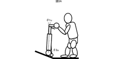
- FIG. 3A is a diagram illustrating the posture of the electric handcart 1 in the first control mode
- FIG. 3B is a diagram illustrating the posture of the electric handcart 1 in the second control mode.
- the first control mode operates uphill.
- the second control mode operates on flat ground.
- the posture of the main body 10 is kept constant by always performing the inverted pendulum control as described above.
- the rotation of the main wheel 11 is driven and controlled so that the angle of the main body 10 with respect to the vertical direction is ⁇ 1u close to 0 degrees.
- the angle formed between the main body portion 10 and the support portion 12 is ⁇ 2u close to 0 degrees.
- the angle formed between the main body 10 and the support 12 is maintained at ⁇ 2u by driving the motor provided at the connecting portion between the main body 10 and the support 12 by the support driving unit 25 under the control of the control unit 21. Be drunk. ⁇ 2u is set to such an angle that the support 12 does not get in the way when the pedestrian pushes the electric handcart 1.
- the support unit drive unit 25 is not an essential component in the present invention, and the support unit 12 may be simply connected to the main body unit 10 so as to be rotatable.
- the posture of the main body portion 10 becomes a vertical direction or a direction close to vertical
- the posture of the support portion 12 is also maintained in the vertical direction or a direction close to vertical due to the weight of the support portion 12 and the auxiliary wheel 13. Therefore, the support part 12 does not interfere with walking.
- the electric wheelbarrow 1 is self-supporting on an uphill, a pedestrian can use the electric wheelbarrow 1 as a wheelbarrow.
- the electric wheelbarrow 1 stops the inverted pendulum control.
- the posture of the main body portion 10 in the second control mode is largely inclined toward the side to which the support portion 12 is connected, and the angle formed by the main body portion 10 and the vertical direction is ⁇ 1 larger than ⁇ 1u. .
- the angle formed between the main body portion 10 and the support portion 12 is ⁇ 2, which is larger than ⁇ 2u.
- the control unit 21 controls the support unit driving unit 25 so that the angle formed by the main body unit 10 and the support unit 12 is ⁇ 2.
- the angle formed by the main body unit 10 and the support unit 12 is different between the support unit 12 and the auxiliary wheel 13. Expanded by its own weight.
- the angle ⁇ 2 formed between the support portion 12 and the main body portion 10 is not increased by a stopper or the like beyond a predetermined angle (for example, 120 degrees), so that the main body portion 10 falls to the side where the support portion 12 is provided. There is no.
- the electric wheelbarrow 1 assists walking when the pedestrian grasps the grip portion 16 even in the second control mode. Moreover, the power consumption of the electric handcart 1 becomes smaller than that in the first control mode by stopping the inverted pendulum control, and the consumption of the battery 40 can be suppressed.
- FIGS. 4A to 4D are diagrams showing an example of switching between the first control mode and the second control mode.
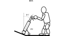
- FIG. 4A is a diagram illustrating the posture of the electric wheelbarrow 1 when approaching an uphill.
- FIG. 4B is a diagram illustrating the posture of the electric wheelbarrow 1 when approaching a flat ground from an uphill.
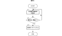
- FIG. 4C is a diagram illustrating a flowchart for switching from the second control mode to the first control mode.
- FIG. 4D is a diagram illustrating a flowchart for switching from the first control mode to the second control mode.
- FIGS. 4A and 4C An example of switching from the second control mode to the first control mode will be described with reference to FIGS. 4A and 4C.
- the angle formed between the main body portion 10 and the vertical direction becomes ⁇ 1 ′ larger than ⁇ 1 because the main body portion 10 is inclined toward the pedestrian side when the main wheel 11 approaches an uphill.
- the control unit 21 detects the angular change of the tilt angle of the main body unit 10 from the gyro sensor 24 periodically (for example, every 1 millisecond), and integrates the main unit 10 with the vertical direction. An angle formed by the direction is detected (s11). When the angle formed between the main body 10 and the vertical direction is larger than the predetermined threshold Th1 (s12), the control unit 21 determines that an uphill has been reached and proceeds to step s13. When the angle formed between the main body 10 and the vertical direction is equal to or smaller than the predetermined threshold Th1, the control unit 21 returns to step s11 and periodically detects the angle formed between the main body 10 and the vertical direction.
- the control unit 21 switches to the first control mode in which the inverted pendulum control is performed so that the angle formed between the main body 10 and the vertical direction becomes ⁇ 1u ( s13).
- the electric wheelbarrow 1 when the electric wheelbarrow 1 approaches an uphill, it switches to the first control mode. Since the electric handcart 1 becomes independent by the inverted pendulum control in the first control mode, the pedestrian can push the electric handcart 1 and go uphill.
- FIGS. 4B and 4D An example of switching from the first control mode to the second control mode will be described with reference to FIGS. 4B and 4D.
- the angle formed by the support portion 12 and the main body portion 10 becomes ⁇ 2 ′ that is larger than ⁇ 2u when the main wheel 11 approaches the flat ground.
- the control unit 21 detects the angle formed by the support unit 12 and the main body unit 10 from the support unit rotary encoder 31 periodically (for example, every 500 milliseconds) in the first control mode (s21). When the angle formed by the support portion 12 and the main body portion 10 is larger than the predetermined threshold Th2 (s22), the control unit 21 determines that the uphill is finished and proceeds to step s23. When the angle formed by the support unit 12 and the main body unit 10 is equal to or less than the predetermined threshold Th2, the control unit 21 determines that the uphill is continued, returns to step s21, and periodically performs a support between the support unit 12 and the main body unit 10. Detect the angle to make.
- the control unit 21 controls the support unit driving unit 25 so that the angle formed by the support unit 12 and the main body unit 10 is ⁇ 2 (s23). ). Then, the control unit 21 switches to the second control mode and stops the inverted pendulum control (s24).
- the electric wheelbarrow 1 switches to the second control mode. Since the electric handcart 1 does not perform the inverted pendulum control in the second control mode, the consumption of the battery 40 can be suppressed.
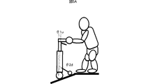
- FIG. 5A is a view showing the posture of the electric handcart 1 in the first control mode on the downhill
- FIG. 5B shows the posture of the electric handcart 1 in the second control mode on the flat ground.
- the posture of the main body 10 is kept constant by always performing the inverted pendulum control as described above.
- the rotation of the main wheel 11 is driven and controlled so that the angle of the main body 10 with respect to the vertical direction is ⁇ 1u.
- the angle ⁇ 2d is smaller than the angle ⁇ 2 at the time of flat ground.
- the electric wheelbarrow 1 stops the inverted pendulum control (the same posture as in FIG. 3B).
- FIG. 6 is a diagram illustrating an example of switching between the first control mode and the second control mode.
- FIG. 6A is a diagram illustrating the posture of the electric wheelbarrow 1 when approaching a downhill.
- FIG. 6B is a diagram illustrating the posture of the electric wheelbarrow 1 when approaching a flat ground from a downhill.
- FIG. 6C is a diagram illustrating a flowchart for switching from the second control mode to the first control mode.
- FIG. 6D is a diagram illustrating a flowchart for switching from the first control mode to the second control mode.
- the angle formed between the main body 10 and the vertical direction is an angle ⁇ 1 ′ smaller than the angle ⁇ 1 because the main wheel 11 approaches the downhill when the downhill is reached. .
- the control unit 21 integrates the value of the gyro sensor 24 periodically (for example, every 500 milliseconds) in the second control mode, and detects the angle formed by the main body unit 10 and the vertical direction (s31). When the angle formed between the main body 10 and the vertical direction is smaller than the predetermined threshold Th3 (s32), the control unit 21 determines that a downhill has been reached and proceeds to step s33. When the angle formed between the main body 10 and the vertical direction is equal to or greater than the predetermined threshold Th3, the control unit 21 returns to step s31 and periodically detects the angle formed between the main body 10 and the vertical direction.
- the control unit 21 switches to the first control mode in which the inverted pendulum control is performed so that the angle formed between the main body 10 and the vertical direction is ⁇ 1u ( s33).
- the electric wheelbarrow 1 when the electric wheelbarrow 1 approaches a downhill, it switches to the first control mode. Since the electric wheelbarrow 1 is self-supporting by the inverted pendulum control in the first control mode, the pedestrian can go downhill while grasping the grip portion 16.
- FIGS. 6B and 6D An example of switching from the first control mode to the second control mode will be described with reference to FIGS. 6B and 6D.
- the angle formed between the support portion 12 and the main body portion 10 is ⁇ 2 ′ that is larger than ⁇ 2d because the main wheel 11 approaches the flat ground.
- the control unit 21 detects the angle formed by the support unit 12 and the main body unit 10 from the support unit rotary encoder 31 periodically (for example, every 500 milliseconds) in the first control mode (s41).
- the control unit 21 determines that the downhill is finished and proceeds to step s43.
- the control unit 21 determines that the downhill continues, returns to step s41, and periodically performs a contact between the support unit 12 and the main body unit 10. Receive the angle to make.
- control unit 21 controls the support unit drive unit 25 so that the angle formed by the support unit 12 and the main body unit 10 is ⁇ 2 (s43). Then, the control unit 21 switches to the second control mode and stops the inverted pendulum control (s44).
- the electric wheelbarrow 1 switches to the second control mode when the main wheel 11 finishes going down the downhill. Since the electric handcart 1 does not perform the inverted pendulum control in the second control mode, the consumption of the battery 40 can be suppressed.
- the control unit 21 can detect the inclination even if an acceleration sensor is used instead of the gyro sensor 24.
- the acceleration in the Z-axis direction detected by the acceleration sensor is smaller than the acceleration in the Z-axis direction on the flat ground when moving from the flat ground to the uphill (or moving from the flat ground to the downhill).
- the control unit 21 detects a decrease in acceleration in the Z-axis direction, the control unit 21 determines that the electric wheelbarrow 1 has moved from the flat ground to the uphill (or from the flat ground to the downhill), and the first control mode starts from the second control mode. Switch to control mode.
- the acceleration in the Z-axis direction is larger than the acceleration in the Z-axis direction on the uphill (or downhill) when moving from the uphill to the flat ground (or moving from the downhill to the flat ground).
- the control unit 21 determines that the electric wheelbarrow 1 has moved from the uphill to the flat ground (or from the downhill to the flat ground), and from the first control mode to the second Switch to control mode.
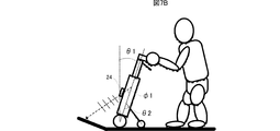
- FIG. 7A is a diagram showing the electric wheelbarrow 1 on a flat ground.
- FIG. 7B is a diagram showing the electric wheelbarrow 1 that has gone uphill.
- FIG. 7C is a diagram illustrating the electric wheelbarrow 1 on an uphill.
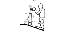
- FIG. 7D is a diagram illustrating the electric wheelbarrow 1 that approaches the flat ground from the uphill.
- the electric wheelbarrow 1 does not perform inverted pendulum control on a flat ground (second control mode), and the angle formed between the main body 10 and the vertical direction is ⁇ 1. Further, the angle formed between the main body 10 and the support 12 is ⁇ 2.
- the electric handcart 1 performs inverted pendulum control in the first control mode on the uphill as shown in FIGS. 7C and 7D. That is, the control unit 21 controls the main wheel drive unit 26 so that the angle formed by the main body unit 10 and the vertical direction is maintained at ⁇ 1u that is smaller than the angle ⁇ 1 on flat ground. Further, the angle formed between the main body 10 and the support 12 is an angle ⁇ 2u that is smaller than the angle ⁇ 2 on flat ground.
- the output angle of the ultrasonic wave emitted from the ultrasonic sensor with respect to the major axis of the main body 10 is ⁇ 1, as shown in FIGS. 7A to 7D.
- the ultrasonic sensor emits ultrasonic waves toward the ground contact surface of the main wheel 11 in the traveling direction and receives reflected waves.
- the time from the ultrasonic emission timing to the timing of receiving the reflected wave corresponds to the distance from the ultrasonic sensor to the ultrasonic reflection point on the ground surface (hereinafter referred to as the round trip distance).
- the reciprocating distance is shorter than the reciprocating distance on a flat ground when the electric wheelbarrow 1 approaches an uphill.
- the round trip time when going uphill is shorter than the round trip time on flat ground.
- the reciprocation distance when the electric wheelbarrow 1 approaches the flat ground from the uphill is longer than the reciprocation distance when the uphill as shown in FIG. 7D. Therefore, the reciprocation time when the electric handcart 1 approaches the flat ground from the uphill is longer than the reciprocation time when the uphill is up.
- FIG. 8 is a diagram showing a flowchart for detecting the uphill of the ground contact surface of the main wheel 11 using an ultrasonic sensor and switching between the first control mode and the second control mode.
- FIG. 8A is a diagram illustrating a flowchart for switching from the second control mode to the first control mode.
- FIG. 8B is a diagram illustrating a flowchart for switching from the first control mode to the second control mode.
- the control unit 21 controls the ultrasonic sensor so as to transmit and receive ultrasonic waves regularly (for example, every 500 milliseconds) in the second control mode (s51). Then, the control unit 21 calculates the ratio of the round trip time measured immediately before the previous round trip time (measured 500 milliseconds before), and when the ratio is smaller than the predetermined threshold Th5 (s52), It is determined that there is an uphill nearby, and the process proceeds to step s53. If the ratio is equal to or greater than the predetermined threshold Th5, the control unit 21 determines that there is no uphill near the traveling direction, returns to step s51, and periodically controls the ultrasonic sensor.
- step s53 is the same as the operation in step s13 in the flowchart shown in FIG. 4C.
- the electric wheelbarrow 1 when the electric wheelbarrow 1 approaches an uphill, it switches to the first control mode. Since the electric handcart 1 is self-supporting by the inverted pendulum control in the first control mode, the pedestrian can walk uphill while holding the grip part 16.
- the control unit 21 controls the ultrasonic sensor so as to transmit and receive ultrasonic waves regularly (for example, every 500 milliseconds) in the first control mode (s61). And the control part 21 calculates the ratio of the round trip time measured immediately before with respect to the round trip time of the last time (measured 500 milliseconds before), and when the said ratio is larger than the predetermined threshold Th6 (s62), It is determined that a flat ground is reached nearby, and the process proceeds to step s63. When the ratio is equal to or less than the threshold Th6, the control unit 21 determines that the uphill continues in the traveling direction, returns to step s61, and periodically controls the ultrasonic sensor.
- step s63 and step s64 are the same as those of step s23 and step 24 in the flowchart shown in FIG. 4D, respectively.
- the electric wheelbarrow 1 when the electric wheelbarrow 1 reaches the flat ground from the uphill, the electric wheelbarrow 1 switches to the second control mode. Since the electric handcart 1 does not perform the inverted pendulum control in the second control mode, the consumption of the battery 40 can be suppressed.
- the round trip time when going downhill is longer than the round trip time on flat ground.
- the round trip time when going downhill to the flat ground is shorter than the round trip time when going downhill.
- control unit 21 can also detect a downhill by using the fluctuation of the round trip time based on the output of the ultrasonic sensor.
- step s52 the ratio of the round-trip time measured immediately before the previous round-trip time is calculated.
- step s53 the process proceeds to step s53, and in step s62, the measurement is performed immediately before the previous round-trip time. If the ratio of the round trip time is calculated and the ratio is smaller than a predetermined threshold, the process proceeds to step s63, which is different from the flowchart shown in FIG.
- the electric wheelbarrow 1 switches between the first control mode and the second control mode by detecting the uphill and the downhill on the ground contact surface of the main wheel 11 with the ultrasonic sensor, and the battery 40 Reduce consumption.
- the tilt may be detected by using the infrared reciprocation time by the infrared sensor instead of the ultrasonic sensor, or the camera may be provided to detect the tilt by image recognition.
- the detection value from the rotary encoder 29 that detects the rotation angle of the main wheel 11 and the load (torque) applied to the main wheel drive unit 26 can also be used.
- the load on the motor is proportional to the magnetic flux and current consumption. Since the magnet in the motor that rotates the main wheel 11 is fixed, the magnetic flux does not change. Therefore, the control unit 21 calculates the load applied to the main wheel driving unit 26 by detecting the current consumption value of the main wheel driving unit 26 (for example, via an observer).
- FIG. 9 is a diagram illustrating an example of detecting that the electric wheelbarrow 1 moves from an uphill to a flat ground based on a detection value from the rotary encoder 29 and a load applied to the main wheel drive unit 26.
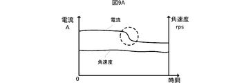
- FIG. 9A is a diagram showing, in time series, the angular velocity of the main wheel 11 and the current consumption value of the main wheel driving unit 26 when moving from an uphill to a flat ground. The angular velocity is obtained by differentiating the rotation angle detected by the rotary encoder 29 with respect to time.
- the control unit 21 reduces the load on the main wheel drive unit 26 when the current consumption value decreases. It can be determined that the vehicle has moved from the uphill to the flat ground.
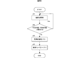
- FIG. 9B is a diagram showing a flowchart for switching from the first control mode to the second control mode based on the angular velocity based on the detection value from the rotary encoder 29 and the load applied to the main wheel drive unit 26.
- the control unit 21 acquires the rotation angle of the main wheel 11 from the rotary encoder 29 periodically (for example, every 500 milliseconds) in the first control mode, and simultaneously acquires the current consumption value of the main wheel drive unit 26. (S71). And the control part 21 calculates
- step s73 When the ratio is equal to or greater than the threshold Th7, the control unit 21 determines that the main wheel 11 is continuously going uphill, returns to step s71, and periodically rotates the rotation angle of the main wheel 11 and the main wheel drive. The current consumption value of the unit 26 is acquired.
- Steps s73 and 74 are the same as steps s23 and s24 in the flowchart shown in FIG. 4D, respectively.
- the electric wheelbarrow 1 can also detect that the descending of the downhill has been completed from the detection value from the rotary encoder 29 and the current consumption value of the main wheel drive unit 26. If the angular velocity is constant, the main wheel drive unit 26 requires a larger force when it is self-supporting on a downhill than when it approaches the flat ground. Therefore, the load on the main wheel drive unit 26 when approaching the flat ground is smaller than that on the downhill. When the angular velocity is substantially constant, the control unit 21 determines that the main wheel 11 has moved from the downhill to the flat ground because the load on the main wheel driving unit 26 has decreased when the current consumption value has decreased. Can do.
- control unit 21 determines that the vehicle has reached the flat ground from the downhill, and the second control is performed from the first control mode. Switch to the control mode.
- control unit 21 can also control the angle formed between the main body unit 10 and the vertical direction to be equal to the inclination angle of the ground contact surface of the main wheel 11 in the first control mode.
- the inclination angle of the ground plane is obtained using an angle formed by the support portion 12 and the main body portion 10 and an angle formed by the main body portion 10 and the vertical direction.
- control unit 21 regenerates the generated electromotive force in the battery 40.
- the main wheel 11 is rotated when the pedestrian pushes the electric wheelbarrow 1 in the second control mode or when going downhill in the first control mode.
- the electromotive force is generated when the motor constituting the main wheel drive unit 26 is rotated.
- the electric wheelbarrow 1 further extends the duration of the battery 40 due to power regeneration.
Landscapes
- Health & Medical Sciences (AREA)
- Epidemiology (AREA)
- Pain & Pain Management (AREA)
- Physical Education & Sports Medicine (AREA)
- Rehabilitation Therapy (AREA)
- Life Sciences & Earth Sciences (AREA)
- Animal Behavior & Ethology (AREA)
- General Health & Medical Sciences (AREA)
- Public Health (AREA)
- Veterinary Medicine (AREA)
- Handcart (AREA)
- Rehabilitation Tools (AREA)
Description
この発明は、歩行を補助する車輪を備えた手押し車に関し、特に車輪を駆動、制御する電動手押し車に関するものである。
従来、車輪を駆動、制御して歩行を補助する歩行補助装置が知られている。例えば、特許文献1には、自走装置および歩行者を柄で接続する機構を備えた歩行支援装置が記載されている。特許文献1の歩行支援装置は、登り坂および下り坂において、柄で歩行者を支えるまたは引っ張る態様で、モータ動力による歩行補助・抑制制御を行う。
歩行を補助する装置は、長時間駆動することが望ましい。しかし、歩行補助装置は、長時間駆動させるための大容量のバッテリを搭載させると、重くなり、製造コストも高くなってしまう。また、電動手押し車は、バッテリが消耗した場合でも、電動機構を備えていない手押し車としても取り回ししやすく使用できることが望ましい。
そこで、本発明は、車輪の駆動機構を制御し、電力消費を抑え、長時間駆動することができる電動手押し車を提供することを目的とする。
本発明の手押し車は、第1の車輪と、該第1の車輪を回転可能に支持する本体部と、該本体部に一方が連結され、ピッチ方向に回転することが可能な支持部と、該支持部の他方に回転可能に支持された第2の車輪と、前記第1の車輪を駆動・制御する駆動制御部と、前記第1の車輪の接地面の傾斜を検知する傾斜検知手段と、前記本体部のピッチ方向の角度変化を検出するピッチ角センサ部と、該駆動制御部、該傾斜検知手段およびピッチ角センサ部を作動させるための電力を蓄える蓄電部と、を備える。
また、本発明の手押し車の前記駆動制御部は、前記傾斜検知手段で傾斜を検知した場合に、前記ピッチ角センサ部の出力に基づいて、前記本体部の角度変化が0となり、かつ前記本体部の鉛直方向に対する角度が、所定の角度になるように前記第1の車輪の回転を制御する第1の制御モードと、前記傾斜検知手段で傾斜を検知しない場合に、前記第1の車輪の回転を制御しない第2の制御モードと、を有することを特徴とする。
本発明の手押し車は、傾斜検出手段によって、ある程度急な上り坂又は下り坂を検知する。駆動制御部は、傾斜を検知した場合、倒立振子制御により、本体部の鉛直方向に対する角度が所定の角度になるよう、本体部の姿勢を維持する(第1の制御モード)。歩行者は、当該手押し車が自立した状態であるため、上り坂または下り坂において、当該手押し車に掴まりながら歩行することができる。
本発明の手押し車は、傾斜検知手段によって、ほぼ平地の路面を検知する。駆動制御部は、平地であることを検知した場合、第1の車輪の回転を制御せず、倒立振子制御を停止する(第2の制御モード)。本体部は、倒立振子制御を行わなくても、第1の車輪および第2の車輪で支持される。したがって、歩行者は、第2の制御モードでも、当該手押し車に掴まりながら歩行することができる。また、本発明の手押し車は、第2の制御モードでは、駆動制御部が動作しないため、電力消費が抑えられる。したがって、歩行者は、電力消費を抑えながら、手押し車を使用することができる。
本発明の手押し車は、第1の制御モードおよび第2の制御モードを併用することにより、駆動可能な持続時間が延び、歩行者の長時間の歩行を補助することができる。
また、手押し車は、第2の制御モードにおいて、本体部と支持部の成す角度が、第1の制御モードにおける前記角度よりも大きいことを特徴とする。例えば、本体部と支持部の接合点にモータを設けることにより、本体部と支持部の成す角度は、モータ駆動による支持部の回転により、大きくなる。そして、第1の車輪と第2の車輪の間隔は、広くなる。その結果、本体部は、第1の制御モードにおける状態に比べ、より安定する。したがって、歩行者は、より安定した状態となる手押し車に掴まりながら歩行することができる。
また、手押し車は、第2の制御モードにおいて、第1の車輪の回転によって生じる起電力を蓄電部に回生することを特徴とする。発生した起電力を蓄電部に回生することにより、持続時間がさらに延びる。したがって、手押し車は、長時間歩行者を補助することができる。
また、本発明の手押し車の駆動制御部は、プログラムで実現可能である。
この発明の手押し車は、電力消費を抑え、長時間歩行を補助することができる。
図1は、本発明の手押し車の実施形態である電動手押し車1の外観図である。図2は、電動手押し車1の構成を示す制御構成図である。
電動手押し車1は、例えば直方体形状の本体部10を備えている。本体部10は、鉛直方向(図中Z,-Z方向)に長く、奥行き方向(図中Y,-Y方向)に短い形状である。本体部10は、内部に制御用の基板やバッテリ40等を内蔵している。
本体部10の鉛直下方向(-Z方向)の下部のうち、左右(図中X,-X方向)の端部には、2つの主輪11が取り付けられている。2つの主輪11は、同じ軸に取り付けられ、同期して回転する。ただし、2つの主輪11は、それぞれ個別に駆動させ、回転させることも可能である。また、この実施形態においては、主輪11は2輪である例を示しているが、1輪あるいは3輪以上であってもよい。
また、本体部10の鉛直方向(Z方向)上部には、例えば円筒形状のハンドル15の一端が取り付けられ、ハンドル15の他端には、T字型のグリップ部16が取り付けられている。グリップ部16には、電源スイッチ等のユーザインタフェース(図2に示すユーザI/F28)が設けられている。ハンドル15のうち、グリップ部16に近い位置には手動ブレーキ30が取り付けられている。歩行者は、グリップ部16を握るあるいは前腕等をグリップ部16に載せ、グリップ部16と前腕等の摩擦により、電動手押し車1を手押し車として使用する。
なお、本体部10は、実際にはカバーが取り付けられ、内部の基板等が外観上見えないようになっている。
本体部10の背面(-Y方向)には、棒状の支持部12の一端が取り付けられる。支持部12の一端は、本体部10に回転可能に接続されている。支持部12の他端には、補助輪13が取り付けられる。補助輪13は、主輪11とともに地面に設置され、本体部10を支持し、本体部10の転倒を防止する(図3Bを参照)。なお、支持部12および補助輪13は、それぞれ1つに限らず2つ以上あってもよい。なお、支持部12は、必ずしも一端が本体部10に接続されている必要はなく、支持部12の中間部分が本体部10に接続されていてもよい。また、補助輪13は、必ずしも支持部12の他端に取り付けられる必要はなく、支持部12の他端が地面に接しない範囲であれば、支持部12の中間部分に取り付けられてもよい。
次に、電動手押し車1の構成および基本動作について説明する。図2に示すように、電動手押し車1は、制御部21、ROM22、RAM23、ジャイロセンサ24、支持部駆動部25、主輪駆動部26、補助輪駆動部27、ユーザI/F28、ロータリエンコーダ29、支持部用ロータリエンコーダ31、および手動ブレーキ30を備えている。
制御部21は、電動手押し車1を統括的に制御する機能部であり、ROM22に記憶されているプログラムを読み出し、当該プログラムをRAM23に展開することで種々の動作を実現する。ジャイロセンサ24は、本体部10のピッチ方向の角速度を検知し、検知結果を制御部21に出力する。ロータリエンコーダ29は、主輪11の回転角度を検知し、検知結果を制御部21に出力する。支持部用ロータリエンコーダ31は、本体部10と支持部12からなる交差角度を検知し、検知結果を制御部21に出力する。また、電動手押し車1は、本体部10の加速度を検知する加速度センサを備えてもよい。
基本動作として、ジャイロセンサ24は、本体部のピッチ方向(図1におけるX軸を中心とする回転方向)の傾斜角の角度変化を検出し、制御部21に出力する。制御部21は、ジャイロセンサ24の検知結果に基づいて、本体部10の角度変化がゼロとなるように、主輪駆動部26を制御する。主輪駆動部26は、主輪11に取り付けられた軸を回転させるモータを駆動する機能部であり、制御部21の制御に従って主輪11を回転させる。補助輪駆動部27は、補助輪13を駆動する機能部であり、制御部21の制御に従って、補助輪13を回転させる。
ただし、補助輪駆動部27は、本発明の必須の構成ではない。
このようにして、電動手押し車1は、基本動作として、倒立振子制御を行い、本体部10の姿勢を一定に保つように制御する。電動手押し車1は、歩行者がグリップ部16を握って電動手押し車1を押した場合でも一定の姿勢を保つため、歩行者が手押し車として用いることができる。
電動手押し車1は、上記倒立振子制御を停止しても、主輪11および補助輪13により本体部10を支持するため、手押し車として使用することができる。
図3Aは、第1の制御モード時の電動手押し車1の姿勢を示す図であり、図3Bは、第2の制御モード時の電動手押し車1の姿勢を示す図である。第1の制御モードは、上り坂で動作する。第2の制御モードは、平地で動作する。
図3Aに示す第1の制御モード時には、上述したように倒立振子制御を常に行うことにより、本体部10の姿勢を一定に保つ。ここでは、本体部10の鉛直方向に対する角度が0度に近いθ1uとなるように主輪11の回転を駆動、制御する。このとき、本体部10と支持部12との成す角度は、0度に近いθ2uとなっている。
本体部10と支持部12との成す角度は、制御部21の制御に従って、支持部駆動部25が本体部10と支持部12との接続部分に設けられたモータを駆動することによりθ2uに保たれる。θ2uは、歩行者が電動手押し車1を押した場合に、支持部12が邪魔にならない程度の角度に設定されている。
ただし、支持部駆動部25は、本発明において必須の構成ではなく、支持部12が本体部10に、回転可能に接続されているだけでもよい。この場合、本体部10の姿勢が鉛直方向あるいは鉛直に近い方向になった場合に、支持部12および補助輪13の自重により、支持部12の姿勢も鉛直方向あるいは鉛直に近い方向に維持されるため、支持部12が歩行の邪魔になることがない。
以上のように、電動手押し車1は、上り坂において自立するため、歩行者は、電動手押し車1を手押し車として使用することができる。
図3Bに示す第2の制御モード時には、電動手押し車1は、上記倒立振子制御を停止する。第2の制御モード時における本体部10の姿勢は、支持部12が接続された側に大きく傾いた状態となり、本体部10と鉛直方向との成す角度は、θ1uよりも大きいθ1となっている。このとき、本体部10と支持部12との成す角度は、θ2uよりも大きいθ2となっている。制御部21は、本体部10と支持部12との成す角度がθ2になるように支持部駆動部25を制御する。支持部駆動部25が設けられず、支持部12が本体部10に回転可能に接続されているだけの場合も、本体部10と支持部12のなす角は、支持部12および補助輪13の自重により、広げられる。なお、支持部12と本体部10との成す角度θ2は、ストッパー等により、所定の角度(例えば120度)以上大きくならないため、本体部10は、支持部12が設けられた側に転倒することはない。
電動手押し車1は、第2の制御モードにおいても、歩行者がグリップ部16をつかむことにより、歩行を補助する。また、電動手押し車1の消費電力は、倒立振子制御を停止することにより、第1の制御モード時より小さくなり、バッテリ40の消費を抑えることができる。
図4A~図4Dは、第1の制御モードと第2の制御モードを切り替える例を示す図である。図4Aは、上り坂に差し掛かった際の電動手押し車1の姿勢を示す図である。図4Bは、上り坂から平地に差し掛かった際の電動手押し車1の姿勢を示す図である。図4Cは、第2の制御モードから第1の制御モードに切り替えるフローチャートを示す図である。図4Dは、第1の制御モードから第2の制御モードに切り替えるフローチャートを示す図である。
第2の制御モードから第1の制御モードに切り替える例を、図4Aおよび図4Cを用いて説明する。図4Aに示すように、本体部10と鉛直方向との成す角度は、主輪11が上り坂に差し掛かることにより、本体部10が歩行者側に傾くため、θ1より大きいθ1’になる。
制御部21は、第2の制御モードにおいて、定期的(例えば1ミリ秒毎)にジャイロセンサ24から、本体部10の傾斜角の角度変化を検出し、積分することにより、本体部10と鉛直方向の成す角度を検出する(s11)。制御部21は、本体部10と鉛直方向の成す角度が所定の閾値Th1より大きい場合(s12)、上り坂に差し掛かったと判断してステップs13に進む。制御部21は、本体部10と鉛直方向の成す角度が所定の閾値Th1以下の場合、ステップs11に戻り、定期的に本体部10と鉛直方向の成す角度を検出する。
本体部10と鉛直方向の成す角度が閾値Th1より大きい場合、制御部21は、本体部10と鉛直方向との成す角度がθ1uとなるように倒立振子制御を行う第1の制御モードに切り替える(s13)。
このように、電動手押し車1は、上り坂に差し掛かると、第1の制御モードに切り替える。電動手押し車1は、第1の制御モードにおいて、倒立振子制御により自立するため、歩行者は、電動手押し車1を押して上り坂を上ることができる。
第1の制御モードから第2の制御モードに切り替える例を、図4Bおよび図4Dを用いて説明する。図4Bに示すように、支持部12と本体部10の成す角度は、主輪11が平地に差し掛かることにより、θ2uより大きいθ2’となる。
制御部21は、第1の制御モードにおいて、定期的(例えば500m秒毎)に支持部用ロータリエンコーダ31から、支持部12と本体部10とのなす角度を検出する(s21)。制御部21は、支持部12と本体部10とのなす角度が所定の閾値Th2より大きい場合(s22)、上り坂を上り終わると判断してステップs23に進む。制御部21は、支持部12と本体部10とのなす角度が所定の閾値Th2以下の場合、上り坂が続くと判断し、ステップs21に戻り、定期的に支持部12と本体部10とのなす角度を検出する。
支持部12と本体部10とのなす角度が閾値Th2より大きい場合、制御部21は、支持部駆動部25を、支持部12と本体部10との成す角度をθ2となるよう制御する(s23)。そして、制御部21は、第2の制御モードに切り替え、倒立振子制御を停止する(s24)。
このように、電動手押し車1は、主輪11が上り坂を上り終わると、第2の制御モードに切り替える。電動手押し車1は、第2の制御モードにおいて、倒立振子制御を行わないため、バッテリ40の消費を抑えることができる。
次に、図5Aは、下り坂における第1の制御モード時の電動手押し車1の姿勢を示す図であり、図5Bは、平地における第2の制御モード時の電動手押し車1の姿勢を示す図である。
図5Aに示す第1の制御モード時には、上述したように倒立振子制御を常に行うことにより、本体部10の姿勢を一定に保つ。ここでは、本体部10の鉛直方向に対する角度がθ1uとなるように主輪11の回転を駆動、制御する。角度θ2dは、平地時の角度θ2より小さい。
図5Bに示す第2の制御モード時には、電動手押し車1は、上記倒立振子制御を停止する(図3Bと同じ姿勢である)。
図6は、第1の制御モードと第2の制御モードを切り替える例を示す図である。図6Aは、下り坂に差し掛かった際の電動手押し車1の姿勢を示す図である。図6Bは、下り坂から平地に差し掛かった際の電動手押し車1の姿勢を示す図である。図6Cは、第2の制御モードから第1の制御モードに切り替えるフローチャートを示す図である。図6Dは、第1の制御モードから第2の制御モードに切り替えるフローチャートを示す図である。
第2の制御モードから第1の制御モードに切り替える例を図6Aおよび図6Cを用いて説明する。図6Aに示すように、本体部10と鉛直方向との成す角度は、下り坂に差し掛かると、主輪11が下り坂に差し掛かることにより、角度θ1よりも小さい角度θ1’となっている。
制御部21は、第2の制御モードにおいて、定期的(例えば500ミリ秒毎)にジャイロセンサ24の値を積分して、本体部10と鉛直方向の成す角度を検出する(s31)。制御部21は、本体部10と鉛直方向の成す角度が所定の閾値Th3より小さい場合(s32)、下り坂に差し掛かったと判断してステップs33に進む。制御部21は、本体部10と鉛直方向の成す角度が所定の閾値Th3以上の場合、ステップs31に戻り、定期的に本体部10と鉛直方向の成す角度を検出する。
本体部10と鉛直方向の成す角度が閾値Th3より小さい場合、制御部21は、本体部10と鉛直方向との成す角度がθ1uとなるように倒立振子制御を行う第1の制御モードに切り替える(s33)。
このように、電動手押し車1は、下り坂に差し掛かると、第1の制御モードに切り替える。電動手押し車1は、第1の制御モードにおいて、倒立振子制御により自立するため、歩行者は、グリップ部16に掴まりながら下り坂を下ることができる。
第1の制御モードから第2の制御モードに切り替える例を、図6Bおよび図6Dを用いて説明する。図6Bに示すように、支持部12と本体部10の成す角度は、主輪11が平地に差し掛かることにより、θ2dより大きいθ2’となっている。
制御部21は、第1の制御モードにおいて、定期的(例えば500ミリ秒毎)に支持部用ロータリエンコーダ31から、支持部12と本体部10とのなす角度を検出する(s41)。制御部21は、支持部12と本体部10とのなす角度が所定の閾値Th4より大きい場合(s42)、下り坂を下り終わると判断してステップs43に進む。制御部21は、支持部12と本体部10とのなす角度が所定の閾値Th4以下の場合、下り坂が続くと判断し、ステップs41に戻り、定期的に支持部12と本体部10とのなす角度を受け取る。
次に、制御部21は、支持部駆動部25を、支持部12と本体部10との成す角度をθ2になるよう制御する(s43)。そして、制御部21は、第2の制御モードに切り替え、倒立振子制御を停止する(s44)。
このように、電動手押し車1は、主輪11が下り坂を下り終わると、第2の制御モードに切り替える。電動手押し車1は、第2の制御モードにおいて、倒立振子制御を行わないため、バッテリ40の消費を抑えることができる。
なお、制御部21は、ジャイロセンサ24の代わりに加速度センサを用いても、傾斜を検出することができる。加速度センサで検出されるZ軸方向の加速度は、平地から上り坂に移動した場合(または平地から下り坂に移動した場合)、平地におけるZ軸方向の加速度よりも小さくなる。制御部21は、Z軸方向の加速度の低下を検出した場合、電動手押し車1が平地から上り坂に(または平地から下り坂に)移動したと判断し、第2の制御モードから第1の制御モードに切り替える。Z軸方向の加速度は、上り坂から平地に移動した場合(または下り坂から平地に移動した場合)、上り坂(または下り坂)におけるZ軸方向の加速度よりも大きくなる。制御部21は、Z軸方向の加速度の上昇を検出した場合、電動手押し車1が上り坂から平地に(または下り坂から平地に)移動したと判断し、第1の制御モードから第2の制御モードに切り替える。
上り坂および下り坂の検知手法は、上述の例に限らない。例えば、図7に示すように、超音波センサを用いて、主輪11の接地面が傾斜していることを検知することもできる。図7Aは、平地における電動手押し車1を示す図である。図7Bは、上り坂に差し掛かった電動手押し車1を示す図である。図7Cは、上り坂における電動手押し車1を示す図である。図7Dは、上り坂から平地に差し掛かる電動手押し車1を示す図である。
電動手押し車1は、図7Aおよび図7Bに示すように、平地では倒立振子制御を行わず(第2の制御モード)、本体部10と鉛直方向との成す角度は、θ1となっている。また、本体部10と支持部12とのなす角度は、θ2となっている。
電動手押し車1は、図7Cおよび図7Dに示すように、上り坂では、第1の制御モードで、倒立振子制御を行う。すなわち、制御部21は、本体部10と鉛直方向との成す角度が平地における角度θ1より小さいθ1uで維持されるよう、主輪駆動部26を制御する。また、本体部10と支持部12との成す角度は、平地における角度θ2より小さい角度θ2uとなっている。
超音波センサから発射される超音波の本体部10の長軸に対する出力角度は、図7A乃至図7Dに示すように、φ1となっている。超音波センサは、進行方向の主輪11の接地面に向かって超音波を発射し、反射波を受け取る。超音波の発射タイミングから反射波を受け取るタイミングまでの時間(以下往復時間と称す。)は、超音波センサから接地面における超音波の反射点までの距離(以下、往復距離と称す。)に対応する。往復距離は、図7Bに示すように、電動手押し車1が上り坂に差し掛かる場合、平地における往復距離より短くなる。したがって、上り坂に差し掛かる際の往復時間は、平地における往復時間より、短くなる。電動手押し車1が上り坂から平地に差し掛かる際の往復距離は、図7Dに示すように上り坂を上る際の往復距離より長くなる。したがって、電動手押し車1が上り坂から平地に差し掛かる際の往復時間は、上り坂を上る際の往復時間より長くなる。
以上のことから、制御部21は、超音波センサの出力に基づく往復時間の変動を用いて、上り坂を検出することができる。図8は、超音波センサを用いて、主輪11の接地面の上り坂を検出し、第1の制御モードと第2の制御モードを切り替えるフローチャートを示す図である。図8Aは、第2の制御モードから第1の制御モードへ切り替えるフローチャートを示す図である。図8Bは、第1の制御モードから第2の制御モードへ切り替えるフローチャートを示す図である。
制御部21は、第2の制御モードにおいて、定期的に(例えば500ミリ秒毎)、超音波を送受信するように超音波センサを制御する(s51)。そして、制御部21は、前回(500ミリ秒前に測定した)の往復時間に対する直前に測定した往復時間の比率を算出し、当該比率が所定の閾値Th5より小さい場合(s52)、進行方向の近くに上り坂があると判断し、ステップs53に進む。制御部21は、当該比率が所定の閾値Th5以上の場合、進行方向の近くに上り坂がないと判断し、ステップs51に戻り、定期的に超音波センサを制御する。
ステップs53の動作は、図4Cに示すフローチャートのステップs13の動作と同じ動作である。
このように、電動手押し車1は、上り坂に差し掛かると、第1の制御モードに切り替える。電動手押し車1は、第1の制御モードにおいて、倒立振子制御により自立するため、歩行者は、グリップ部16に掴まりながら上り坂を歩行することができる。
制御部21は、第1の制御モードにおいて、定期的に(例えば500ミリ秒毎)、超音波を送受信するように超音波センサを制御する(s61)。そして、制御部21は、前回(500ミリ秒前に測定した)の往復時間に対する直前に測定した往復時間の比率を算出し、当該比率が所定の閾値Th6より大きい場合(s62)、進行方向の近くで平地に差し掛かると判断し、ステップs63に進む。制御部21は、当該比率が閾値Th6以下の場合、進行方向に上り坂が続くと判断し、ステップs61に戻り、定期的に超音波センサを制御する。
ステップs63およびステップs64の動作は、それぞれ図4Dに示すフローチャートのステップs23およびステップ24と同じ動作である。
このように、電動手押し車1は、上り坂から平地に差し掛かると、第2の制御モードに切り替える。電動手押し車1は、第2の制御モードにおいて、倒立振子制御を行わないため、バッテリ40の消費を抑えることができる。
下り坂に差し掛かる際の往復時間は、平地における往復時間より、長くなる。下り坂から平地に差し掛かる際の往復時間は、下り坂を下る際の往復時間より短くなる。
以上のことから、制御部21は、超音波センサの出力に基づく往復時間の変動を用いて、下り坂を検出することもできる。
制御部21が下り坂を検出する処理の流れは、図8に示すフローチャートに示す処理の流れとほぼ同じである。ステップs52において、前回の往復時間に対する直前に測定した往復時間の比率を算出し、当該比率が所定の閾値より大きい場合、ステップs53に進む点と、ステップs62において、前回の往復時間に対する直前に測定した往復時間の比率を算出し、当該比率が所定の閾値より小さい場合、ステップs63に進む点が、図8に示すフローチャートと異なる点である。
以上のように、電動手押し車1は、超音波センサで主輪11の接地面における上り坂および下り坂を検出することにより、第1の制御モードと第2の制御モードを切り替え、バッテリ40の消費を抑える。
なお、超音波センサではなく、赤外線センサによる赤外線の往復時間を用いて、傾斜を検出してもよいし、カメラを設け、画像認識で傾斜を検出してもよい。
また、傾斜から平地に移動したことを検出するために、主輪11の回転角度を検出するロータリエンコーダ29からの検出値および主輪駆動部26にかかる負荷(トルク)を用いることもできる。
一般に、モータにかかる負荷は、磁束および消費電流値に比例する。主輪11を回転させるモータ内の磁石は固定されているため、磁束は変化しない。したがって、制御部21は、主輪駆動部26の消費電流値を(例えばオブザーバを介して)検出することにより、主輪駆動部26にかかる負荷を算出する。
図9は、ロータリエンコーダ29からの検出値および主輪駆動部26にかかる負荷に基づいて、電動手押し車1が上り坂から平地に移動することを検出する例を示す図である。図9Aは、上り坂から平地に移動する際の主輪11の角速度および主輪駆動部26の消費電流値を時系列に示す図である。角速度は、ロータリエンコーダ29で検出した回転角度を時間で微分することにより求められる。
主輪駆動部26は、角速度が一定であれば、平地に差し掛かった場合よりも上り坂を上る場合の方が、大きな力を必要とする。したがって、平地に差し掛かった時の主輪駆動部26の負荷は、上り坂の時に比べ小さい。制御部21は、角速度がほぼ一定の場合、図9Aの破線部に示すように、消費電流値が小さくなる時点で、主輪駆動部26の負荷が小さくなったことから、電動手押し車1が上り坂から平地に移動したと判断することができる。
図9Bは、ロータリエンコーダ29からの検出値に基づく角速度および主輪駆動部26にかかる負荷に基づいて、第1の制御モードから第2の制御モードに切り替えるフローチャートを示す図である。制御部21は、第1の制御モードにおいて、定期的に(例えば500ミリ秒毎)、ロータリエンコーダ29から主輪11の回転角度を取得し、同時に主輪駆動部26の消費電流値を取得する(s71)。そして、制御部21は、主輪11の角速度(回転角度の微分値)に対する消費電流値の比率を求め、当該比率が所定の閾値Th7より小さい場合(s72)、主輪11が上り坂から平地に移動したと判断し、ステップs73に進む。制御部21は、当該比率が閾値Th7以上の場合、主輪11が継続して上り坂を上っていると判断し、ステップs71に戻り、定期的に主輪11の回転角度および主輪駆動部26の消費電流値を取得する。
ステップs73およびステップ74の動作は、それぞれ図4Dに示すフローチャートのステップs23およびステップs24と同じ動作である。
電動手押し車1は、ロータリエンコーダ29からの検出値および主輪駆動部26の消費電流値から、下り坂を下り終わったことも検出することもできる。主輪駆動部26は、角速度が一定であれば、平地に差し掛かった場合よりも下り坂で自立する場合の方が、大きな力を必要とする。したがって、平地に差し掛かった時の主輪駆動部26の負荷は、下り坂の時に比べ小さい。制御部21は、角速度がほぼ一定の場合、消費電流値が小さくなる時点で、主輪駆動部26の負荷が小さくなったことから、主輪11が下り坂から平地に移動したと判断することができる。制御部21は、主輪11の角速度に対する主輪駆動部26の消費電流値の比率が所定の閾値より小さくなった場合、下り坂から平地に差し掛かったと判断し、第1の制御モードから第2の制御モードに切り替える。
また、制御部21は、第1の制御モードで、本体部10と鉛直方向との成す角度を、主輪11の接地面の傾斜角度と等しくなるように制御することもできる。接地面の傾斜角度は、支持部12と本体部10との成す角度、および本体部10と鉛直方向との成す角度を用いて求められる。本体部10と鉛直方向との成す角度を接地面の傾斜角度として倒立振子制御を行う場合、グリップ部16とユーザの距離は、急な傾斜面でも、離れることはない。
また、制御部21は、発生する起電力をバッテリ40に回生することが好ましい。第2の制御モードで歩行者が電動手押し車1を押すことにより、または第1の制御モードで下り坂を下る際に主輪11は、回転される。起電力は、主輪駆動部26を構成するモータが回転されることによって、発生する。電動手押し車1は、電力回生により、さらにバッテリ40の持続時間が延びる。
1…電動手押し車
10…本体部
11…主輪
12…支持部
13…補助輪
15…ハンドル
16…グリップ部
21…制御部
22…ROM
23…RAM
24…ジャイロセンサ
25…支持部駆動部
26…主輪駆動部
27…補助輪駆動部
28…ユーザI/F
29…ロータリエンコーダ
30…手動ブレーキ
31…支持部用ロータリエンコーダ
40…バッテリ
10…本体部
11…主輪
12…支持部
13…補助輪
15…ハンドル
16…グリップ部
21…制御部
22…ROM
23…RAM
24…ジャイロセンサ
25…支持部駆動部
26…主輪駆動部
27…補助輪駆動部
28…ユーザI/F
29…ロータリエンコーダ
30…手動ブレーキ
31…支持部用ロータリエンコーダ
40…バッテリ
Claims (4)
- 第1の車輪と、
該第1の車輪を回転可能に支持する本体部と、
該本体部に一方が連結され、ピッチ方向に回転することが可能な支持部と、
該支持部の他方に回転可能に支持された第2の車輪と、
前記第1の車輪を駆動・制御する駆動制御部と、
前記第1の車輪の接地面の傾斜を検知する傾斜検知手段と、
前記本体部のピッチ方向の角度変化を検出するピッチ角センサ部と、
該駆動制御部、該傾斜検知手段、およびピッチ角センサ部を作動させるための電力を蓄える蓄電部と、
を備えた手押し車であって、
前記駆動制御部は、前記傾斜検知手段が傾斜を検知した場合に、前記ピッチ角センサ部の出力に基づいて、前記本体部の角度変化が0となり、かつ前記本体部の鉛直方向に対する角度が、所定の角度になるように前記第1の車輪の回転を制御する第1の制御モードと、
前記傾斜検知手段で傾斜を検知しない場合に、前記第1の車輪の回転を制御しない第2の制御モードと、
を有することを特徴とする手押し車。 - 前記第2の制御モードにおいて、前記本体部と前記支持部の成す角度が、前記第1の制御モードにおける前記角度よりも大きいことを特徴とする請求項1に記載の手押し車。
- 前記第2の制御モードにおいて、前記第1の車輪の回転によって生じる起電力を前記蓄電部に回生することを特徴とする請求項1または請求項2に記載の手押し車。
- 第1の車輪と、
該第1の車輪を回転可能に支持する本体部と、
該本体部に一方が連結され、ピッチ方向に回転することが可能な支持部と、
該支持部の他方に回転可能に支持された第2の車輪と、
前記第1の車輪を駆動・制御する駆動制御部と、
前記第1の車輪の接地面の傾斜を検知する傾斜検知手段と、
前記本体部のピッチ方向の角度変化を検出するピッチ角センサ部と、
該駆動制御部、該傾斜検知手段、およびピッチ角センサ部を作動させるための電力を蓄える蓄電部と、
を備えた手押し車を制御するプログラムであって、
前記駆動制御部に、前記傾斜検知手段が傾斜を検知した場合に、前記ピッチ角センサ部の出力に基づいて、前記本体部の角度変化が0となり、かつ前記本体部の鉛直方向に対する角度が、所定の角度になるように前記第1の車輪の回転を制御する第1の制御モードと、
前記傾斜検知手段で傾斜を検知しない場合に、前記第1の車輪の回転を制御しない第2の制御モードと、
を実行させることを特徴とするプログラム。
Priority Applications (1)
| Application Number | Priority Date | Filing Date | Title |
|---|---|---|---|
| JP2014536731A JP5704285B2 (ja) | 2012-09-18 | 2013-09-03 | 手押し車 |
Applications Claiming Priority (2)
| Application Number | Priority Date | Filing Date | Title |
|---|---|---|---|
| JP2012203924 | 2012-09-18 | ||
| JP2012-203924 | 2012-09-18 |
Publications (1)
| Publication Number | Publication Date |
|---|---|
| WO2014045858A1 true WO2014045858A1 (ja) | 2014-03-27 |
Family
ID=50341176
Family Applications (1)
| Application Number | Title | Priority Date | Filing Date |
|---|---|---|---|
| PCT/JP2013/073608 Ceased WO2014045858A1 (ja) | 2012-09-18 | 2013-09-03 | 手押し車 |
Country Status (2)
| Country | Link |
|---|---|
| JP (1) | JP5704285B2 (ja) |
| WO (1) | WO2014045858A1 (ja) |
Cited By (1)
| Publication number | Priority date | Publication date | Assignee | Title |
|---|---|---|---|---|
| JPWO2021132216A1 (ja) * | 2019-12-25 | 2021-07-01 |
Citations (3)
| Publication number | Priority date | Publication date | Assignee | Title |
|---|---|---|---|---|
| JPH11267162A (ja) * | 1998-03-19 | 1999-10-05 | Eiji Matsuura | 歩行補助車 |
| WO2010134664A1 (ko) * | 2009-05-21 | 2010-11-25 | Jang Suk Ho | 발전 겸용 전동기에 의한 추진력을 갖는 자전거 |
| WO2012114597A1 (ja) * | 2011-02-23 | 2012-08-30 | 株式会社村田製作所 | 歩行補助車 |
Family Cites Families (4)
| Publication number | Priority date | Publication date | Assignee | Title |
|---|---|---|---|---|
| JP4411415B2 (ja) * | 2003-09-08 | 2010-02-10 | 株式会社 東北テクノアーチ | パッシブ型移動台車 |
| JP2007090019A (ja) * | 2005-09-29 | 2007-04-12 | Hiroshi Okamura | 歩行支援システム |
| JP2009183405A (ja) * | 2008-02-05 | 2009-08-20 | Toyota Motor Corp | 歩行補助装置 |
| JP5350157B2 (ja) * | 2009-09-25 | 2013-11-27 | コーア株式会社 | 歩行補助車 |
-
2013
- 2013-09-03 JP JP2014536731A patent/JP5704285B2/ja not_active Expired - Fee Related
- 2013-09-03 WO PCT/JP2013/073608 patent/WO2014045858A1/ja not_active Ceased
Patent Citations (3)
| Publication number | Priority date | Publication date | Assignee | Title |
|---|---|---|---|---|
| JPH11267162A (ja) * | 1998-03-19 | 1999-10-05 | Eiji Matsuura | 歩行補助車 |
| WO2010134664A1 (ko) * | 2009-05-21 | 2010-11-25 | Jang Suk Ho | 발전 겸용 전동기에 의한 추진력을 갖는 자전거 |
| WO2012114597A1 (ja) * | 2011-02-23 | 2012-08-30 | 株式会社村田製作所 | 歩行補助車 |
Cited By (4)
| Publication number | Priority date | Publication date | Assignee | Title |
|---|---|---|---|---|
| JPWO2021132216A1 (ja) * | 2019-12-25 | 2021-07-01 | ||
| WO2021132216A1 (ja) * | 2019-12-25 | 2021-07-01 | ナブテスコ株式会社 | 電動歩行補助車 |
| CN114867444A (zh) * | 2019-12-25 | 2022-08-05 | 纳博特斯克有限公司 | 电动步行辅助车 |
| JP7220810B2 (ja) | 2019-12-25 | 2023-02-10 | ナブテスコ株式会社 | 電動歩行補助車 |
Also Published As
| Publication number | Publication date |
|---|---|
| JPWO2014045858A1 (ja) | 2016-08-18 |
| JP5704285B2 (ja) | 2015-04-22 |
Similar Documents
| Publication | Publication Date | Title |
|---|---|---|
| JP5716873B2 (ja) | 移動体 | |
| US9969086B1 (en) | Achieving a target gait in a legged robot based on steering commands | |
| US20210147202A1 (en) | Systems and methods for operating autonomous tug robots | |
| JP6232873B2 (ja) | 手押し車およびプログラム | |
| JP5943154B2 (ja) | 手押し車 | |
| JP6156504B2 (ja) | 手押し車 | |
| US20150066242A1 (en) | Walking assistance moving vehicle | |
| US20150066328A1 (en) | Walking assistance moving vehicle | |
| WO2013099091A1 (ja) | 自走式ロボットハンド | |
| JP2016202609A (ja) | 歩行補助車 | |
| JP5958581B2 (ja) | 手押し車 | |
| JP5704285B2 (ja) | 手押し車 | |
| JP2004295429A (ja) | ロボットの目標軌道データ設定方法 | |
| US20230135665A1 (en) | Torque assisted surface maintenance machine | |
| JP5800110B2 (ja) | 手押し車 | |
| JP2007223399A (ja) | 車両 | |
| JPWO2015019982A1 (ja) | 手押し車 | |
| JP2014168967A (ja) | 手押し車 | |
| KR20190041596A (ko) | 탑승형 서비스 로봇 및 그 제어방법 | |
| Sayidmarie et al. | Real-time validation of a novel two-wheeled robot with a dynamically moving payload | |
| JP6373235B2 (ja) | モータの制御装置 |
Legal Events
| Date | Code | Title | Description |
|---|---|---|---|
| 121 | Ep: the epo has been informed by wipo that ep was designated in this application |
Ref document number: 13839390 Country of ref document: EP Kind code of ref document: A1 |
|
| ENP | Entry into the national phase |
Ref document number: 2014536731 Country of ref document: JP Kind code of ref document: A |
|
| NENP | Non-entry into the national phase |
Ref country code: DE |
|
| 122 | Ep: pct application non-entry in european phase |
Ref document number: 13839390 Country of ref document: EP Kind code of ref document: A1 |