WO2014045822A1 - フロートガラスの製造装置および製造方法 - Google Patents
フロートガラスの製造装置および製造方法 Download PDFInfo
- Publication number
- WO2014045822A1 WO2014045822A1 PCT/JP2013/073094 JP2013073094W WO2014045822A1 WO 2014045822 A1 WO2014045822 A1 WO 2014045822A1 JP 2013073094 W JP2013073094 W JP 2013073094W WO 2014045822 A1 WO2014045822 A1 WO 2014045822A1
- Authority
- WO
- WIPO (PCT)
- Prior art keywords
- side wall
- glass
- float
- supply path
- float bath
- Prior art date
- Legal status (The legal status is an assumption and is not a legal conclusion. Google has not performed a legal analysis and makes no representation as to the accuracy of the status listed.)
- Ceased
Links
Images


Classifications
-
- C—CHEMISTRY; METALLURGY
- C03—GLASS; MINERAL OR SLAG WOOL
- C03B—MANUFACTURE, SHAPING, OR SUPPLEMENTARY PROCESSES
- C03B5/00—Melting in furnaces; Furnaces so far as specially adapted for glass manufacture
- C03B5/16—Special features of the melting process; Auxiliary means specially adapted for glass-melting furnaces
- C03B5/26—Outlets, e.g. drains, siphons; Overflows, e.g. for supplying the float tank, tweels
- C03B5/265—Overflows; Lips; Tweels
- C03B5/267—Overflows; Lips; Tweels specially adapted for supplying the float tank
-
- C—CHEMISTRY; METALLURGY
- C03—GLASS; MINERAL OR SLAG WOOL
- C03B—MANUFACTURE, SHAPING, OR SUPPLEMENTARY PROCESSES
- C03B18/00—Shaping glass in contact with the surface of a liquid
- C03B18/02—Forming sheets
- C03B18/20—Composition of the atmosphere above the float bath; Treating or purifying the atmosphere above the float bath
-
- Y—GENERAL TAGGING OF NEW TECHNOLOGICAL DEVELOPMENTS; GENERAL TAGGING OF CROSS-SECTIONAL TECHNOLOGIES SPANNING OVER SEVERAL SECTIONS OF THE IPC; TECHNICAL SUBJECTS COVERED BY FORMER USPC CROSS-REFERENCE ART COLLECTIONS [XRACs] AND DIGESTS
- Y02—TECHNOLOGIES OR APPLICATIONS FOR MITIGATION OR ADAPTATION AGAINST CLIMATE CHANGE
- Y02P—CLIMATE CHANGE MITIGATION TECHNOLOGIES IN THE PRODUCTION OR PROCESSING OF GOODS
- Y02P40/00—Technologies relating to the processing of minerals
- Y02P40/50—Glass production, e.g. reusing waste heat during processing or shaping
- Y02P40/57—Improving the yield, e-g- reduction of reject rates
Definitions
- the present invention relates to a float glass manufacturing apparatus and manufacturing method.
- the method for producing float glass continuously supplies molten glass onto the surface of molten tin stored in a float bath, and heats the molten glass with a plurality of heaters, while bringing the molten glass along the surface of the molten metal.
- This is a method for producing a plate glass by flowing in a predetermined direction and forming a ribbon glass ribbon having a desired width and thickness.
- Float molding can produce plate glass with high productivity and excellent flatness, so it is widely used in, for example, the production of architectural plate glass and display panel substrate glass, and proposals to improve the quality of the glass obtained are proposed. It has been made conventionally.
- a float glass manufacturing method nitrogen gas is blown into a space (twill space) formed by two twills that adjust the flow rate of molten glass supplied from a melting furnace and molten glass, and the pressure in the twill space is reduced.
- a technique for maintaining the pressure higher than the pressure of a spout that is a section from a twill to a float bath is known (see Patent Document 1). By giving this pressure difference, it is possible to prevent tin vapor flowing from the float bath into the spout from flowing into the twill space. Then, Kyashiteraito tin vapor and oxygen react to produce (SnO 2) crystals can be prevented from adhering to a movable part Towiru.
- SnO 2 Kyashiteraito tin vapor and oxygen react to produce
- the float bath and the spout are separated by the front wall, that is, the front lintel, and a lip for molten glass inflow is formed on the bottom side of the spout.
- a weiring wheel is provided, and the structure is complicated.
- These parts are composed of a combination of heat-resistant materials such as bricks and have a certain level of airtightness, but there are many gaps such as the need for gaps in the moving parts of the wheel, so there is no leakage from the outside. It is not a structure that can be completely suppressed.
- the seam portion of heat-resistant materials is filled with a sealing material, but glass-based sealing materials are prone to cracking, and cement-based sealing materials are susceptible to cracking when dried. Sealing materials such as water glass However, since a large number of holes are formed when dried, there is a problem that leakage prevention cannot be realized completely.
- the present inventor has developed a float glass production apparatus and production capable of suppressing the generation of tin oxide around the portion where molten glass flows into the float bath and obtaining high-quality glass with few defects.
- the purpose is to provide a method.
- molten glass supplied from a melting furnace is supplied to a float bath via a supply path and a spout part, and is made to flow along the surface of molten tin stored in the float bath to form a strip-like glass ribbon.
- a float glass manufacturing apparatus for molding wherein the supply path, the spout part, and the inlet part of the float bath are each configured by combining a plurality of heat-resistant materials, and surround a supply path tip portion constituted by the heat-resistant material.
- a first side wall provided with an opening
- a second side wall provided with an opening surrounding the inlet part of the float bath made of the heat-resistant material, and arranged to face the first side wall
- the spout part A cover body comprising a third and a fourth side wall that is located outside the first side wall and connects the first and second side walls, and a ceiling wall connected to the side walls; Said Is disposed so as to cover the out part of the inlet portion of the float bath, characterized in that the blowing opening of the non-oxidizing gas on the side wall of the cover body is formed.
- the periphery of the tip of the molten glass supply path, the spout and the inlet of the float bath can be covered with the non-oxidizing gas.
- the tip of the molten glass supply path, the spout part, and the inlet part of the float bath have a complex structure that combines heat-resistant materials, so leaks inevitably occur, and the atmosphere of the installation environment starts around these parts. Gas enters.
- the inside of the cover body is always filled with a non-oxidizing gas, atmospheric gas in the installation environment has entered from the leaked portions of the tip portion of the molten glass supply path, the spout portion, and the inlet portion of the float bath.
- a seal piece for filling a gap between the heat-resistant material and the inner peripheral edge of the opening may be attached to the inner peripheral edge of the opening of the first side wall and the inner peripheral edge of the opening of the second side wall.
- High quality glass ribbon can be provided.
- the cover body includes a metal frame member provided along a peripheral edge of the side wall and the ceiling wall, and a plate member integrated with the frame member, and the plate member includes the side wall and the side wall. It can be set as the structure which comprises the said ceiling wall. If the cover body is made of a metal frame member and a plate member, the assembly is simple and can be widely applied to glass ribbon manufacturing apparatuses of various sizes. In addition, the airtightness of the cover body can be improved.
- the non-oxidizing gas inlet may be formed on both the left and right sides of the first side wall bottom.
- the gas flow flows between the tip of the molten glass supply path, the spout and the inlet of the float bath. It can be introduced in a balanced manner from the left and right so that it does not directly hit the surroundings. For this reason, it is possible to suppress the turbulence of gas that entrains air inside the cover body, and to fill the inside of the cover body with the non-oxidizing gas.
- the non-oxidizing property that does not contribute to the formation of the cathelite crystals It can be gas.
- a front tool for damming a part of the molten glass flowing inside the supply path and adjusting the flow rate is provided at the tip of the supply path of the molten glass, and is upstream of the installation position of the front tool. It can be set as the structure by which the said 1st side wall was installed in the side.
- the front twill is inserted into the tip of the molten glass supply path and comes into contact with the molten glass to adjust the flow of the molten glass, so there are many leaking parts around the front twill on the tip side of the molten glass supply path. It is formed.
- a structure in which oxygen is not introduced to the front end side of the molten glass supply path can be provided by reliably covering the portion with a lot of leakage with the cover body.
- a front lintel may be provided at the entrance of the float bath, and the second side wall may be provided so as to surround the front lintel. Since the structure is also complicated on the inlet side of the float bath, there are many portions that leak from the joints of the heat-resistant material. A structure in which oxygen is not introduced to the inlet side of the float bath can be realized by reliably covering the portion with a large leak with the cover body.
- molten glass supplied from a melting furnace is supplied to a float bath via a supply path and a spout part, and is made to flow along the surface of molten tin stored in the float bath to form a strip-like glass ribbon.
- a method for manufacturing float glass in which a front end of a supply path, a spout, and an inlet of a float bath made of a heat-resistant material are covered with a cover body composed of a side wall and a ceiling wall,
- the present invention relates to a float glass manufacturing method of forming a glass ribbon while supplying the molten glass to the float bath through the supply path and a spout part in a state where an oxidizing gas is filled.
- the periphery of the tip portion of the molten glass supply path, the spout portion, and the inlet portion of the float bath can be covered with the non-oxidizing gas. Since the tip part of the molten glass supply path, the spout part and the part of the inlet part of the float bath have a complicated structure, leaks inevitably occur, and atmospheric gas enters from the periphery of these parts.
- the inside of the cover body is always filled with a non-oxidizing gas, it is assumed that the surrounding atmospheric gas has entered from the leaked portion of the tip portion of the molten glass supply path, the spout portion, and the inlet portion of the float bath.
- the first side wall provided with an opening portion surrounding the supply path tip portion constituted by the heat resistant material, and the opening portion surrounding the inlet portion of the float bath constituted by the heat resistant material.
- a second side wall disposed so as to face the side wall, third and fourth side walls located outside the spout portion and connecting the first and second side walls, and a ceiling connected to the side walls
- a cover body made of a wall can be used.
- a seal piece for filling a gap between the heat resistant material and the inner peripheral edge of the opening may be attached to the inner peripheral edge of the opening of the first side wall and the inner peripheral edge of the opening of the second side wall.
- High quality glass ribbon can be provided.
- the non-oxidizing gas blowing ports are formed on both the left and right sides of the first side wall bottom so that the non-oxidizing gas can be blown evenly from both the blowing ports.
- the flow of gas flows between the tip of the molten glass supply path, the spout and the float bath.
- Non-oxidizing gas can be introduced in a balanced manner from the left and right so that it does not directly hit the periphery of the inlet.
- the inside of the cover body can be filled with a non-oxidizing gas so that the oxygen concentration inside the cover body can be 0.3% or less. If the oxygen concentration inside the cover main body is 0.3% or less, defects due to cassiterite crystals on the surface of the glass ribbon to be produced can be extremely reduced.
- the periphery of the tip portion of the molten glass supply path, the spout portion, and the inlet portion of the float bath can be covered with the non-oxidizing gas. Since the tip part of the molten glass supply path, the spout part, and the part of the inlet part of the float bath have complicated structures, leaks inevitably occur, and ambient gas in the installation environment enters from the periphery of these parts.
- FIG. 1 is a configuration diagram of a float glass manufacturing apparatus including a molten glass supply path, a spout unit, and a float bath according to the first embodiment of the present invention.
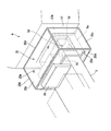
- FIG. 2 is a perspective view showing an attachment state of the cover body provided in the float glass manufacturing apparatus.
- FIG. 3 is a configuration diagram of the cover body.
- the float glass manufacturing apparatus 1 of the present embodiment flows molten glass G that flows from a melting furnace 2 over a lip 5 via a molten glass supply path 3 and is supplied to a float bath 6.
- the apparatus is configured as a device for forming a strip-like glass ribbon 8 by flowing along the surface of molten tin 7 provided in a float bath 6.
- the glass ribbon 8 is taken out from the outlet of the float bath 6, cooled in a not-shown layer (slow cooling furnace), washed, and then cut into predetermined dimensions.
- the supply path 3 is constructed by assembling a plurality of heat-resistant materials such as refractory bricks in the shape of a passage to form a horizontally elongated flow path 10, inside the hollow front block 11 provided at the front end of the supply path 3, at the tip.
- a lip 5 having a slope 5a that gradually becomes thinner is provided.
- the supply path 3 is provided with a ceiling 3A, and a cooling front wall 12 is constructed on the ceiling 3A.
- a front wheel 15 and a back wheel 16 are suspended from a distal end portion of the supply path 3 by a crane device (not shown) so as to freely move up and down.
- the front twill 15 is installed so as to penetrate up and down through an insertion hole formed in the ceiling portion 3A near the tip of the supply path 3.
- the front twill 15 is moved up and down by the crane device, and the ratio of blocking the flow path 10 in the supply path can be adjusted, whereby the amount of the molten glass G flowing on the lip 5 can be adjusted.
- the molten glass G whose flow rate is controlled by the front twill 15 is supplied to the float bath 6 from the tip of the lip 5.
- a front lintel 17 is provided at the inlet of the float bath 6, and the molten glass G flowing from the lip 5 flows down onto the molten tin 7 on the front side of the front lintel 17.
- the front tween 15 and the front tween 15 are provided with a front surface of the front lintel 17, a float bath 6 below the front lintel 17, a portion provided with the lip 5 on the front end side of the supply path 3 provided on the front side of the front lintel 17
- the enclosed area is referred to as a spout portion 21.
- the ceiling portion of the spout portion 21 is covered with a heat-resistant material 22 provided so as to extend the ceiling portion 3A of the supply path 3, and the side portion of the spout portion 21 is also covered with a heat-resistant material (not shown). Since the bottom part of the spout part 21 is installed so that the inlet part 6A of the float bath 6 covers the bottom part, the spout part 21 is a semi-sealed space surrounded by these members.
- a cover main body 25 is provided so as to cover the front end side of the supply path 3, the part facing the lip 5, the spout part 21, the part of the inlet part 6 ⁇ / b> A of the float bath 6, and the front part side of the front lintel 17. It has been.
- the cover main body 25 is formed in a box shape from a frame member 25A in which a metal frame material is assembled in a rectangular frame shape, and a plurality of metal plate members 25B that are fitted inside the frame member 25A and constitute a wall portion. Is formed.
- the first side wall 25a is configured by the plate member 25B installed on the front end side of the supply path 3
- the second side wall 25b is configured by the plate member 25B installed on the front lintel 17 side. ing.
- a third side wall 25c and a fourth side wall 25c are constituted by a plate member 25B connecting these side portions, and the first side wall 25a and the second side wall 25c are formed.
- a ceiling wall 25d is constituted by a plate member 25B that covers the ceiling side of the side wall 25b, the third side wall 25c, and the fourth side wall 25c.
- 1st opening 25e is formed in the center side of the 1st side wall 25a, and the strip
- a second opening 25g is formed on the second side wall 25b so as to extend from the bottom to the top, and a strip-shaped sealing piece 25h made of a heat-resistant cloth is provided on the inner peripheral edge of the second opening 25g.
- the heat-resistant cloth is composed of a cloth piece of a heat-resistant material such as glass cloth or silica cloth.
- the first opening 25e formed in the first side wall 25a is formed to have a width and height that can be inserted through the distal end side of the supply path 3, and the first side wall 25a is formed between the front and back wheels 15 and 16. It is installed so that the front end side of the supply path 3 can be inserted through the first opening 25e.
- the second opening 25g formed in the second side wall 25b is formed to have a width and height that can be inserted through the inlet 6A side of the float bath 6, and the second side wall 25b is located on the front side of the front lintel 17. It is located so as to be able to pass through the inlet 6A side of the float bath 6 through the second opening 25g and surround the periphery thereof.
- Communication holes 25k for supplying a non-oxidizing gas such as an inert gas are formed in the left and right sides of the bottom of the first side wall 25a.
- the ceiling wall 25d has two communication holes 25m for measuring the internal atmosphere.
- a non-oxidizing gas supply device (not shown) is connected to the communication hole 25k formed in the first side wall 25a so that a non-oxidizing gas such as an inert gas can be supplied into the cover body 25. It is configured.
- a gas component measuring device (not shown) and a pressure measuring device (not shown) are connected to the communication hole 25m formed in the ceiling wall 25d, and a gas component including an oxygen concentration inside the cover body 25 is detected to measure an internal pressure. It is configured to be able to.
- a portion located above the front tween 15 is formed with a through-hole through which a wire connected to the crane device for lifting and lowering the twill is formed.
- the front twill 15 is suspended so as to be movable up and down without being interfered with the cover body 25.
- the communication holes 25k formed on the left and right of the bottom portion of the first side wall 25a surround the spout portion 21 when a non-oxidizing gas such as nitrogen gas is evenly supplied from these positions into the cover body 25. It can supply without blowing a nitrogen gas flow directly on the member side. In order to fill the inside of the cover body 25 with nitrogen gas, it is necessary to supply nitrogen gas to the inside of the cover body 25 using a strong gas flow, so that the communication holes 25k are positioned on both sides of the bottom of the first side wall 25a.
- the communication hole 25m formed in the ceiling wall 25d is located sufficiently away from the communication hole 25k of the first side wall 25a, when measuring the internal atmosphere of the cover body 25, the gas flow from the communication hole 25k The internal atmosphere of the cover body 25 can be measured without being affected.
- the molten glass G is supplied from the melting furnace 2 to the supply path 3 and flows over the lip 5. Is supplied onto the molten tin 7 at the inlet 6 ⁇ / b> A of the float bath 6 while adjusting the flow rate of the above by the amount of damming of the front twill 15.
- the glass ribbon 8 can be obtained by using the molten glass G flowing on the molten tin 7 as a strip-shaped glass ribbon 8 having a predetermined width and thickness.
- the target plate glass can be obtained by transporting to a subsequent cooling furnace and cutting apparatus and cutting to a target size.
- the main component of the float bath 6 is an inert gas such as nitrogen gas in order to prevent the molten glass G flowing on the surface of the molten tin 7 from deteriorating.
- This gas contains a reducing hydrogen gas in order to prevent the vapor of molten tin 7 from being oxidized to produce a cassiterite crystal.
- the gas supplied to the float bath 6 is discharged to the outside through a duct (not shown) provided on the ceiling of the float bath 6.
- a part of the gas supplied to the float bath 6 reduces the gap between the lower end of the front wall 18 of the front lintel 17 and the molten glass G below the front lintel 17 to prevent the gas from flowing into the spout portion 21 side. Even if it is, it partially passes through this gap and reaches the spout portion 21 side. For this reason, since a part of the tin vapor is mixed inside the spout part 21, if oxygen is present inside the spout part 21, there is a possibility that a cassiterite crystal is generated.
- the internal pressure of the cover main body 25 is controlled from atmospheric pressure to (atmospheric pressure + float bath pressure).
- atmospheric pressure for example, if the pressure in the float bath 6 is assumed to be 5 to 25 Pa, the pressure in the cover body 25 is preferably set to a pressure in the range of 1 atm to (1 atm + 5 Pa to 25 Pa).
- the cover main body 25 of the present embodiment covers the spout portion 21 and the front twill 15 and the portion of the float bath 6 on the inlet 6A side. For this reason, even if a leak occurs, by covering portions that are highly likely to be leaked with a cover body 25 and surrounding those portions with a non-oxidizing gas, The structure allows non-oxidizing gas to enter. For this reason, even if tin vapor enters into the inside of the spout portion 21, the glass ribbon 8 can be manufactured without generating a cassiterite crystal. Therefore, there is an effect that it is possible to manufacture a high-quality glass ribbon 8 that is free from defects caused by the formation of the cassiterite crystal.
- a heat-resistant cloth seal piece 25f is provided in the first opening 25e to prevent air from entering the cover main body 25 from around the tip of the supply path 3.
- a heat-resistant cloth seal piece 25h can be provided in the second opening 25g to prevent air from entering from the portion around the inlet 6A side of the float bath 6 into the cover body.
- the cover main body 25 used in the present embodiment has its side wall covered with a metal plate member 25B, but transparent glass, Teflon (registered trademark) is provided on the third side wall 25c and the fourth side wall 25c side of the plate member 25B.
- Teflon registered trademark
- Polytetrafluoroethylene is preferably provided so that the inside can be monitored.
- the side walls and the ceiling wall may be made of a sheet material such as a Teflon (registered trademark) sheet.
- the frame member 25A may be formed of a metal frame, and the plate member 25B may be bonded or fitted and fixed. However, the plate member 25B is preferably configured to be replaceable with a new one.
- the glass ribbon production apparatus shown in FIG. 1 is used, and the glass for the display device is float-molded under the following conditions in a steady state. Adherence of the cassiterite crystals was confirmed. Float bath tin vapor concentration 6mg / m 3 , spout tin vapor concentration 0.5mg / m 3 , float bath hydrogen concentration 7vol%, spout portion hydrogen concentration 0.2vol%, nitrogen supply to spout portion the amount 100 Nm 3 / time, nitrogen supply amount 10 Nm 3 / time to float bath was operated by setting the spacing 15mm clearance of the front phosphorus ether.
- the flow rate of nitrogen gas supplied into the cover body was adjusted to adjust the oxygen concentration inside the cover body. Furthermore, when the oxygen concentration of the spout part obtained by that was also measured and the glass ribbon was produced in the state, the number of the faults resulting from the fall of a cassiterite crystal
- the oxygen concentration in the cover body 21% ⁇ the oxygen concentration in the spout 0.013% ⁇ the number of defects: 350 cps / m 2 .
- Oxygen concentration in the cover body 10% ⁇ oxygen concentration in the spout 0.011% ⁇ number of defects: 250 cps / m 2 .
- Oxygen concentration in cover main body 2% ⁇ oxygen concentration in spout 0.0013% ⁇ number of defects: 110 cps / m 2 .
- Oxygen concentration in cover main body 1% ⁇ oxygen concentration in spout 0.0006% ⁇ number of defects: 45 cps / m 2 .
- Oxygen concentration in cover main body 0.3% ⁇ oxygen concentration in spout 0.0002% ⁇ number of defects: 4 cps / m 2 .
- Oxygen concentration in cover main body 0.1% ⁇ oxygen concentration in spout 0.00005% ⁇ number of defects: 0.5 cps / m 2 .
- the technology of the present invention can be widely applied to an apparatus and a method for forming a glass ribbon by performing a float process.
Landscapes
- Chemical & Material Sciences (AREA)
- Engineering & Computer Science (AREA)
- Materials Engineering (AREA)
- Organic Chemistry (AREA)
- Glass Compositions (AREA)
- Furnace Details (AREA)
Abstract
Description
この圧力差を与えることにより、フロートバスからスパウトに流入した錫蒸気がトウィル空間に流入することを防止できる。そして、錫蒸気と酸素が反応して生成されるキャシテライト(SnO2)結晶が可動部であるトウィルに付着することを防止できる。なお、キャシテライト結晶は溶融ガラス表面に落下して付着するとガラスの欠点となる可能性がある。この種キャシテライト結晶の落下物は、外径数10μm程度の黒色の酸化物粒子として知られている。
また、耐熱材の継ぎ目の部分はシール材を用いて隙間埋めを行うが、ガラス系のシール材は割れが入りやすく、セメント系のシール材は乾燥するとひびが入りやすく、水ガラスなどのシール材も乾燥すると多数の孔が生成するので、リーク防止は完全には実現できない問題がある。
側壁開口部の内周縁にシール片を設けることでカバー本体の各側壁が溶融ガラス供給経路の先端部とスパウト部とフロートバスの入口部の周囲を高い密着性で覆うので、カバー本体内部側への酸素の侵入を抑制できる。このため、溶融ガラス供給経路の先端部の内側とスパウト部の内側とフロートバスの入口部の内側において錫蒸気を酸化させるおそれが少なくなり、キャシテライト結晶の生成と成長に起因する欠陥を生じていない高品質のガラスリボンを提供できる。
金属製の枠組み部材とプレート部材からなるカバー本体であるならば、組み立てが簡単で種々なサイズのガラスリボン製造装置に広汎に適用ができる。また、カバー本体の気密性を良好とすることが可能となる。
非酸化性ガスの吹込口を側壁底部の両側に設けることでカバー本体の内部に非酸化性ガスを吹き込む際、そのガス流が溶融ガラス供給経路の先端部とスパウト部とフロートバスの入口部の周囲に直接当たらないように左右からバランス良く導入できる。このため、カバー本体の内部側に空気を巻き込むようなガスの乱れを抑制し、カバー本体内部を非酸化性ガスで満たすことができる。よって溶融ガラス供給経路の先端部とスパウト部とフロートバスの入口部の内側にリークなどによってカバー本体内部のガスが流入したとしても、リークにより侵入するガスをキャシテライト結晶の生成に関与しない非酸化性ガスとすることができる。
フロントツイールは溶融ガラスの供給経路の先端部に挿入されて溶融ガラスに接触し、溶融ガラスの流れを調整するので溶融ガラスの供給経路先端側のフロントツイールの周囲にはリークする部分が多く形成される。このリークが多い部分を確実にカバー本体で覆うことで、溶融ガラスの供給経路先端部側へ酸素を導入しない構造を提供できる。
フロートバスの入口部側においても構造が複雑なため、耐熱材の継ぎ目などからリークする部分が多く形成される。このリークが多い部分を確実にカバー本体で覆うことで、フロートバスの入口部側へ酸素を導入しない構造を実現できる。
ここで、カバー本体の内部に常に非酸化性ガスを満たしておくならば、溶融ガラス供給経路の先端部とスパウト部とフロートバスの入口部の部分のリーク部分から周囲の雰囲気ガスが侵入したとしても、これらの内部には非酸化性のガスが侵入するのみであり、酸素が侵入する割合は少なくなるので、錫蒸気と酸素が反応する確率が少なくなる。これにより、錫酸化物としてのキャシテライト結晶が生成することがなく、キャシテライト結晶が成長するおそれが少なくなり、ガラスリボンの上にキャシテライト結晶の成長物が落下するおそれも少なくなる。このため、欠点の少ない高品質のガラスリボンを得ることができる。
各側壁と天井壁で供給経路先端部の周囲とフロートバスの入口部の周囲とスパウト部の周囲を囲む構成のカバー本体とすることにより、これらの部分周りを確実に覆うことができる構造を提供できる。
側壁開口部の内周縁にシール片を設けることでカバー本体の各側壁が溶融ガラス供給経路の先端部とスパウト部とフロートバスの入口部の周囲を良好な密着性で覆うので、カバー本体内部側への酸素の侵入を抑制できる。このため、溶融ガラス供給経路の先端部の内側とスパウト部の内側とフロートバスの入口部の内側において錫蒸気を酸化させるおそれが少なくなり、キャシテライト結晶の生成と成長に起因する欠陥を生じていない高品質のガラスリボンを提供できる。
非酸化性ガスの吹込口を側壁底部の両側に設けこれらから均等にカバー本体の内部に非酸化性ガスを吹き込むことにより、そのガス流が溶融ガラス供給経路の先端部とスパウト部とフロートバスの入口部の周囲に直接当たらないように左右からバランス良く非酸化性ガスを導入できる。このため、カバー本体の内部側に空気を巻き込むようなガスの乱れを抑制し、カバー本体内部を非酸化性ガスで満たすことができる。よって溶融ガラス供給経路の先端部とスパウト部とフロートバスの入口部の内側にリークなどによってカバー本体内部のガスが流入したとしても、リークにより侵入するガスをキャシテライト結晶の生成に関与しない非酸化性ガスとすることができる。
カバー本体内部の酸素濃度を0.3%以下とするならば、製造されるガラスリボン表面のキャシテライト結晶に起因する欠点を極めて少なくすることができる。
図1に示すように、本実施形態のフロートガラスの製造装置1は、溶融炉2から溶融ガラスの供給経路3を介しリップ5の上を流れてフロートバス6に供給された溶融ガラスGを、フロートバス6に湛えられた溶融錫7の表面に沿って流動させて帯板状のガラスリボン8を成形する装置として構成されている。ガラスリボン8はフロートバス6の出口部から取り出された後、図示略のレヤー(徐冷炉)にて冷却され、洗浄された後、所定の寸法に切断される。
カバー本体25は、金属製のフレーム材を矩形枠状に組み付けた枠組み部材25Aと、この枠組み部材25Aの内側に嵌め込まれて壁部を構成する金属製の複数のプレート部材25Bとから箱状に形成されている。カバー本体25において、供給経路3の先端側に設置されているプレート部材25Bにより第1の側壁25aが構成され、フロントリンテル17側に設置されているプレート部材25Bにより第2の側壁25bが構成されている。第1の側壁25aと第2の側壁25bの間にはこれらの側部どうしを接続するプレート部材25Bにより第3の側壁25c、第4の側壁25cが構成され、第1の側壁25a、第2の側壁25b、第3の側壁25c、第4の側壁25cの天井側を覆うプレート部材25Bにより天井壁25dが構成されている。
第1の側壁25aに形成されている連通孔25kには、図示略の非酸化性ガスの供給装置が接続され、カバー本体25の内部に不活性ガスなどの非酸化性ガスを供給できるように構成されている。天井壁25dに形成された連通孔25mには、図示略のガス成分測定装置と圧力測定装置が接続されていて、カバー本体25の内側の酸素濃度を含むガス成分を検知し、内部圧力を測定できるように構成されている。
なお、図面では略しているが、天井壁25dにおいて、フロントツイール15の上方に位置する部分には、ツイール上下昇降用のクレーン装置に接続されるワイヤーを挿通する透孔が形成されていて、フロントツイール15はカバー本体25に干渉されることなく上下移動自在に吊り下げられている。
また、天井壁25dに形成した連通孔25mは第1の側壁25aの連通孔25kから充分に離間した位置にあるので、カバー本体25の内部雰囲気を測定する際、連通孔25kからのガス流に影響されずにカバー本体25の内部雰囲気を測定できる。
フロートバス6内の水素量をキャシテライト結晶が成長しない程度の水素量とすることは容易であるが、スパウト部21に多くの水素ガスを流入させると、スパウト部21において水が生成していまい、好ましくないので、スパウト部21に水素を多く送ることはできず、このためスパウト部21においてキャシテライト結晶が成長するおそれがある。
そこで、本実施形態の製造装置1では、ガラスリボン8を製造する場合、カバー本体25の内部に窒素ガスなどの非酸化性ガスを満たした状態で上述のようにガラスリボン8を製造する。ガラスリボン8の製造時、カバー本体25の内部圧力を大気圧から(大気圧+フロートバス内圧力)の間の圧力に制御しておくことが好ましい。例えば、フロートバス6内の圧力を5~25Paと仮定するならば、カバー本体25内の圧力を1気圧~(1気圧+5Pa~25Pa)の範囲内の圧力とすることが好ましい。
また、本実施形態のカバー本体25にあっては、第1の開口部25eに耐熱布のシール片25fを設けて供給経路3の先端部周りからカバー本体25内への空気の混入を抑制し、第2の開口部25gに耐熱布のシール片25hを設けてフロートバス6の入口部6A側周りの部分からカバー本体内への空気の混入を抑制することができる。
フロートバスの錫蒸気濃度6mg/m3、スパウト部の錫蒸気濃度0.5mg/m3、フロートバスの水素濃度7体積%、スパウト部の水素濃度0.2体積%、スパウト部への窒素供給量100Nm3/時間、フロートバスへの窒素供給量10Nm3/時間、フロントリンテルの隙間の間隔15mmに設定して運転した。
カバー本体内酸素濃度:10%→スパウト内酸素濃度0.011%→欠点数:250cps/m2。
カバー本体内酸素濃度:2%→スパウト内酸素濃度0.0013%→欠点数:110cps/m2。
カバー本体内酸素濃度:1%→スパウト内酸素濃度0.0006%→欠点数:45cps/m2。
カバー本体内酸素濃度:0.3%→スパウト内酸素濃度0.0002%→欠点数:4cps/m2。
カバー本体内酸素濃度:0.1%→スパウト内酸素濃度0.00005%→欠点数:0.5cps/m2。
このため、カバー本体内の酸素濃度を0.3%以下に調整することが望ましく、0.1%以下に調整することがより好ましい。
Claims (11)
- 溶融炉から供給された溶融ガラスを供給経路とスパウト部を介しフロートバスに供給し、該フロートバスに蓄えられた溶融錫の表面に沿って流動させて帯板状のガラスリボンに成形するフロートガラスの製造装置であって、
前記供給経路と前記スパウト部と前記フロートバスの入口部がそれぞれ複数の耐熱材を組み合わせて構成され、
前記耐熱材により構成された供給経路先端部を囲む開口部を備えた第1の側壁と、前記耐熱材により構成されたフロートバスの入口部を囲む開口部を備え前記第1の側壁に対向するよう配置された第2の側壁と、前記スパウト部の外側に位置して前記第1、第2の側壁を接続する第3、第4の側壁と、これら側壁に接続された天井壁とを具備してなるカバー本体が、前記供給経路先端部と前記スパウト部と前記フロートバスの入口部を覆うように設置され、前記カバー本体の側壁に非酸化性ガスの吹込口が形成されたフロートガラスの製造装置。 - 前記第1の側壁の開口部内周縁と前記第2の側壁の開口部内周縁に、前記耐熱材と前記開口部内周縁との隙間を埋めるシール片が貼設された請求項1に記載のフロートガラスの製造装置。
- 前記カバー本体が前記側壁と前記天井壁の周縁に沿って設けられた金属製の枠組み部材と、該枠組み部材に一体化されたプレート部材とからなり、前記プレート部材が前記側壁と前記天井壁を構成している請求項1または2に記載のフロートガラスの製造装置。
- 前記非酸化性ガスの吹込口が前記第1の側壁底部の左右両側に形成された請求項1~3のいずれか一項に記載のフロートガラスの製造装置。
- 前記溶融ガラスの供給経路先端部に該供給経路内部を流れる溶融ガラスの一部を堰き止めて流量調整するためのフロントツイールが設けられ、このフロントツイールの設置位置よりも上流側に前記第1の側壁が設置された請求項1~4のいずれか一項に記載のフロートガラスの製造装置。
- 前記フロートバスの入口部にフロントリンテルが設けられ、このフロントリンテルの周囲を囲むように前記第2の側壁が設けられた請求項1~5のいずれか一項に記載のフロートガラスの製造装置。
- 溶融炉から供給された溶融ガラスを供給経路とスパウト部を介しフロートバスに供給し、該フロートバスに蓄えられた溶融錫の表面に沿って流動させて帯板状のガラスリボンに成形するフロートガラスの製造方法であって、
耐熱材により構成された供給経路先端部とスパウト部とフロートバスの入口部を側壁と天井壁とからなるカバー本体で覆い、該カバー本体の内部に非酸化性ガスを満たした状態で、前記溶融ガラスを前記供給経路とスパウト部を介し前記フロートバスに供給しつつガラスリボンを成形するフロートガラスの製造方法。 - 前記カバー本体が、前記耐熱材により構成された供給経路先端部を囲む開口部を備えた第1の側壁と、前記耐熱材により構成されたフロートバスの入口部を囲む開口部を備え前記第1の側壁に対向するよう配置された第2の側壁と、前記スパウト部の外側に位置して前記第1、第2の側壁を接続する第3、第4の側壁と、これら側壁に接続された天井壁とからなる請求項7に記載のフロートガラスの製造方法。
- 前記第1の側壁の開口部内周縁と前記第2の側壁の開口部内周縁に、前記耐熱材と前記開口部内周縁との隙間を埋めるシール片が貼設された請求項7または8に記載のフロートガラスの製造方法。
- 前記非酸化性ガスの吹込口を前記第1の側壁底部の左右両側に形成し、両方の吹込口から均等に非酸化性ガスを吹き込む請求項7~9のいずれか一項に記載のフロートガラスの製造方法。
- 前記カバー本体の内部に非酸化性ガスを満たして前記カバー本体内部の酸素濃度を0.3%以下とすることを特徴とする請求項7~10のいずれか一項に記載のフロートガラスの製造方法。
Priority Applications (2)
| Application Number | Priority Date | Filing Date | Title |
|---|---|---|---|
| KR1020157006829A KR20150058225A (ko) | 2012-09-19 | 2013-08-29 | 플로트 유리의 제조 장치 및 제조 방법 |
| CN201380048806.1A CN104640818B (zh) | 2012-09-19 | 2013-08-29 | 浮法玻璃的制造装置和制造方法 |
Applications Claiming Priority (2)
| Application Number | Priority Date | Filing Date | Title |
|---|---|---|---|
| JP2012-206307 | 2012-09-19 | ||
| JP2012206307A JP2015221725A (ja) | 2012-09-19 | 2012-09-19 | フロートガラスの製造装置および製造方法 |
Publications (1)
| Publication Number | Publication Date |
|---|---|
| WO2014045822A1 true WO2014045822A1 (ja) | 2014-03-27 |
Family
ID=50341144
Family Applications (1)
| Application Number | Title | Priority Date | Filing Date |
|---|---|---|---|
| PCT/JP2013/073094 Ceased WO2014045822A1 (ja) | 2012-09-19 | 2013-08-29 | フロートガラスの製造装置および製造方法 |
Country Status (5)
| Country | Link |
|---|---|
| JP (1) | JP2015221725A (ja) |
| KR (1) | KR20150058225A (ja) |
| CN (1) | CN104640818B (ja) |
| TW (1) | TW201418173A (ja) |
| WO (1) | WO2014045822A1 (ja) |
Citations (2)
| Publication number | Priority date | Publication date | Assignee | Title |
|---|---|---|---|---|
| JPS6265941A (ja) * | 1985-09-12 | 1987-03-25 | Asahi Glass Co Ltd | フロ−トガラスの製造装置 |
| JP2010070417A (ja) * | 2008-09-18 | 2010-04-02 | Nippon Electric Glass Co Ltd | ガラス板の製造装置および製造方法 |
-
2012
- 2012-09-19 JP JP2012206307A patent/JP2015221725A/ja active Pending
-
2013
- 2013-08-29 KR KR1020157006829A patent/KR20150058225A/ko not_active Withdrawn
- 2013-08-29 CN CN201380048806.1A patent/CN104640818B/zh active Active
- 2013-08-29 WO PCT/JP2013/073094 patent/WO2014045822A1/ja not_active Ceased
- 2013-09-06 TW TW102132279A patent/TW201418173A/zh unknown
Patent Citations (2)
| Publication number | Priority date | Publication date | Assignee | Title |
|---|---|---|---|---|
| JPS6265941A (ja) * | 1985-09-12 | 1987-03-25 | Asahi Glass Co Ltd | フロ−トガラスの製造装置 |
| JP2010070417A (ja) * | 2008-09-18 | 2010-04-02 | Nippon Electric Glass Co Ltd | ガラス板の製造装置および製造方法 |
Also Published As
| Publication number | Publication date |
|---|---|
| KR20150058225A (ko) | 2015-05-28 |
| JP2015221725A (ja) | 2015-12-10 |
| CN104640818B (zh) | 2017-03-08 |
| TW201418173A (zh) | 2014-05-16 |
| CN104640818A (zh) | 2015-05-20 |
Similar Documents
| Publication | Publication Date | Title |
|---|---|---|
| KR102147684B1 (ko) | 플로트 유리의 제조 방법과 제조 장치 | |
| JP5064526B2 (ja) | フロートガラス製造用フロート槽システム | |
| TWI588101B (zh) | 用於提供乾淨玻璃製造環境的設備與方法 | |
| JP2011251893A (ja) | フロートガラスのための徐冷装置及び方法 | |
| JP5459213B2 (ja) | フロートガラスの製造装置および製造方法 | |
| TW201210965A (en) | Device for depressurizing and defoaming molten glass, method for depressurizing and defoaming molten glass, device for manufacturing glass product, and method for manufacturing glass product | |
| CN104718166B (zh) | 浮法玻璃的成形装置及浮法玻璃的制造方法 | |
| CN110668679B (zh) | 一种浮法玻璃的制造装置及其制造方法 | |
| KR101621999B1 (ko) | 판유리 제조장치 및 제조방법 | |
| US20140308621A1 (en) | Sintering apparatus | |
| JP2015221725A (ja) | フロートガラスの製造装置および製造方法 | |
| CN105377778B (zh) | 浮法玻璃制造装置以及使用该装置的浮法玻璃制造方法 | |
| CN102285754A (zh) | 用于制造浮法玻璃的装置及方法 | |
| JP6206179B2 (ja) | 溶融ガラス供給装置、及びガラス板製造装置 | |
| KR20150076095A (ko) | 플로트 판 유리의 제조 방법 | |
| JP5102591B2 (ja) | 合成シリカガラスの製造装置 | |
| CN107531541B (zh) | 浮法玻璃的制造方法 | |
| JP2015093794A (ja) | フロートガラスの製造方法 | |
| JP5660622B2 (ja) | ガラス板の製造装置及び方法 | |
| JP4132198B2 (ja) | フロート板ガラス製造装置 | |
| JP5615314B2 (ja) | 合成シリカガラスの製造装置及び合成石英ガラスの製造方法 | |
| KR20090030205A (ko) | 에지 롤러용 부싱 장치 및 판 유리의 제조 방법 | |
| JP2008505837A (ja) | フロート法による板ガラスの製造装置及びフロート浴の流出端のシール配置 | |
| JP2008143746A (ja) | ガラス板の製造方法及びその装置並びにフラットパネルディスプレイ用ガラス基板 | |
| KR20120102939A (ko) | 유리판 제조용 성형 롤러, 이를 이용한 유리판 제조 장치 및 방법 |
Legal Events
| Date | Code | Title | Description |
|---|---|---|---|
| 121 | Ep: the epo has been informed by wipo that ep was designated in this application |
Ref document number: 13839415 Country of ref document: EP Kind code of ref document: A1 |
|
| ENP | Entry into the national phase |
Ref document number: 20157006829 Country of ref document: KR Kind code of ref document: A |
|
| NENP | Non-entry into the national phase |
Ref country code: DE |
|
| 122 | Ep: pct application non-entry in european phase |
Ref document number: 13839415 Country of ref document: EP Kind code of ref document: A1 |
|
| NENP | Non-entry into the national phase |
Ref country code: JP |