WO2014045812A1 - 基地局装置、端末装置、通信システム、通信方法および集積回路 - Google Patents
基地局装置、端末装置、通信システム、通信方法および集積回路 Download PDFInfo
- Publication number
- WO2014045812A1 WO2014045812A1 PCT/JP2013/072829 JP2013072829W WO2014045812A1 WO 2014045812 A1 WO2014045812 A1 WO 2014045812A1 JP 2013072829 W JP2013072829 W JP 2013072829W WO 2014045812 A1 WO2014045812 A1 WO 2014045812A1
- Authority
- WO
- WIPO (PCT)
- Prior art keywords
- base station
- station device
- station apparatus
- information
- channel
- Prior art date
- Legal status (The legal status is an assumption and is not a legal conclusion. Google has not performed a legal analysis and makes no representation as to the accuracy of the status listed.)
- Ceased
Links
Images



Classifications
-
- H—ELECTRICITY
- H04—ELECTRIC COMMUNICATION TECHNIQUE
- H04L—TRANSMISSION OF DIGITAL INFORMATION, e.g. TELEGRAPHIC COMMUNICATION
- H04L5/00—Arrangements affording multiple use of the transmission path
- H04L5/14—Two-way operation using the same type of signal, i.e. duplex
- H04L5/1469—Two-way operation using the same type of signal, i.e. duplex using time-sharing
-
- H—ELECTRICITY
- H04—ELECTRIC COMMUNICATION TECHNIQUE
- H04W—WIRELESS COMMUNICATION NETWORKS
- H04W72/00—Local resource management
- H04W72/30—Resource management for broadcast services
-
- H—ELECTRICITY
- H04—ELECTRIC COMMUNICATION TECHNIQUE
- H04L—TRANSMISSION OF DIGITAL INFORMATION, e.g. TELEGRAPHIC COMMUNICATION
- H04L5/00—Arrangements affording multiple use of the transmission path
- H04L5/14—Two-way operation using the same type of signal, i.e. duplex
-
- H—ELECTRICITY
- H04—ELECTRIC COMMUNICATION TECHNIQUE
- H04W—WIRELESS COMMUNICATION NETWORKS
- H04W36/00—Hand-off or reselection arrangements
- H04W36/0005—Control or signalling for completing the hand-off
- H04W36/0055—Transmission or use of information for re-establishing the radio link
- H04W36/0072—Transmission or use of information for re-establishing the radio link of resource information of target access point
-
- H—ELECTRICITY
- H04—ELECTRIC COMMUNICATION TECHNIQUE
- H04W—WIRELESS COMMUNICATION NETWORKS
- H04W48/00—Access restriction; Network selection; Access point selection
- H04W48/08—Access restriction or access information delivery, e.g. discovery data delivery
- H04W48/12—Access restriction or access information delivery, e.g. discovery data delivery using downlink control channel
Definitions
- the present invention relates to a base station device, a terminal device, a communication system, a communication method, and an integrated circuit.
- a communication service area is formed by a cell configuration in which a large number of base station devices are arranged.
- a cell refers to a range in which a base station device can be connected to a terminal device (mobile station device, UE (User Equipment)).
- a cellular system In a system formed by this cell configuration (hereinafter referred to as a cellular system), traffic distribution is required as traffic volume increases due to an increase in large-capacity services.
- a part or all of the range of cells (macrocells) formed by the main base station device (macro base station), and low power base station devices (picocell base stations, femtocell base stations, small cell base stations) It has been proposed to arrange a plurality of base station apparatuses so as to overlap the range of cells (picocells, femtocells, small cells, etc.) configured by (heterogeneous network deployment (HetNet; Heterogeneous Network deployment).
- HetNet Heterogeneous Network deployment
- FIG. 9 is a schematic diagram of a cellular system in the downlink in which a plurality of base station apparatuses having different cell radii are arranged.
- Cell 1000-2a small cell of base station apparatus 1000-2 in which cell 1000-1a (macro cell) of macro base station 1000-1 is a low-power base station having a smaller maximum transmission power than macro base station apparatus, and Each base station apparatus is arranged so as to overlap the cell 1000-3a (small cell) of the base station apparatus 1000-3.
- Base station apparatuses 1000-1, 1000-2 and 1000-3 are connected by optical fiber, X2 interface or other wired or wireless lines. Necessary control information and the like are exchanged between the base station apparatuses through these lines.
- the mobile station device 2000-1 is wirelessly connected (r11) to the base station device 1000-1
- the mobile station device 2000-2 is wirelessly connected (r22) to the base station device 1000-2
- the device 2000-3 is wirelessly connected (r33) to the base station device 1000-3.
- Each mobile station apparatus is controlled so as to be wirelessly connected to, for example, a base station apparatus that can receive a signal with the maximum received electric field strength. In this control, for example, a bias is added to the received electric field strength (Non-Patent Document 2). Thereby, traffic distribution is realized.
- FIG. 10 is an example of a transmission frame format in the downlink of the cellular system.
- one transmission frame is composed of 10 subframes (subframe index # 0 to subframe index # 10).
- a downlink physical signal or physical channel as a downlink physical signal or physical channel, a cell-specific reference signal (CRS; Cell-specific Reference Signal, black portion in the figure), a downlink common channel (PDSCH; Physical Downlink Shared Channel, Channels that mainly transmit information data, white area in the figure), downlink control channel (PDCCH; Physical Downlink Control Channel, shaded part in the figure), synchronization signal (PSS; Primary Synchronization Signal, SSS; Sechronism) Singal), broadcast channel (PBCH; Physical Broa) cast Channel, the grating portions in the figure) are mapped.
- CRS Cell-specific Reference Signal
- PDSCH Physical Downlink Shared Channel, Channels that mainly transmit information data, white area in the figure
- PDCCH Physical Downlink Control Channel, shaded part in the figure
- PSS Primary Synchronization Signal, SSS; Sechronism
- PBCH Physical Broa
- CRS is a signal used for propagation path estimation.
- PDSCH is a channel that mainly transmits information data.
- the PDCCH is a channel used to notify the radio resource allocation information of the terminal device.
- PSS is a signal mainly used for symbol timing synchronization.
- SSS is a signal used for frame synchronization.
- the PBCH is a channel for transmitting control information (for example, MIB in LTE; Master Information Block) necessary for the terminal device to receive the PDSCH.
- Base station apparatuses 1000-1, 1000-2 and 1000-3 in FIG. 9 transmit control information to terminal apparatuses 2000-1, 2000-2 and 2000-3 based on this transmission frame format, respectively. .
- the present invention has been made in view of the above problems, and the object thereof is a communication system in which a plurality of base station devices are arranged so that all or a part of the connectable range of each base station device overlaps.
- An object of the present invention is to provide a base station device, a terminal device, a communication system, a communication method, and an integrated circuit capable of distributing traffic while avoiding complicated control of connection and switching between the base station device and the terminal device.
- each configuration of a base station device, a terminal device, a communication system, a communication method, and an integrated circuit according to the present invention is as follows.
- a base station apparatus includes a plurality of second base station apparatuses arranged so as to overlap a cell range of the first base station apparatus and the first base station apparatus, and the first base station apparatus 1st base station apparatus of a communication system provided with the terminal device connected with 1 base station apparatus or the said 2nd base station apparatus, Comprising:
- reporting channel which notifies alerting
- a base station apparatus is the above base station apparatus, wherein the system information included in the downlink control channel is broadcast information of a second base station apparatus. To do.
- a base station apparatus is the above base station apparatus, wherein the system information included in the downlink control channel is the number of transmission antennas of the second base station apparatus.
- a base station apparatus is the above base station apparatus, and the system information included in the downlink control channel is a system bandwidth of the second base station apparatus.
- a base station apparatus is the above-described base station apparatus, wherein the system information included in the downlink control channel is a system frame number of the second base station apparatus.
- a base station apparatus is the above base station apparatus, and the first base station apparatus includes: An upper layer that determines the connection destination of the terminal device from the peripheral base station measurement results, The upper layer acquires the system information of the second base station apparatus determined as the connection destination from the second base station apparatus.
- the transmission method of the base station apparatus by 1 aspect of this invention WHEREIN: The several 2nd base arrange
- a transmission method of a first base station apparatus of a communication system comprising a station apparatus and a terminal apparatus connected to the first base station apparatus or the second base station apparatus, and broadcast information of the first base station apparatus And a downlink control channel including system information of the second base station apparatus are transmitted.
- a terminal device includes a plurality of second base station devices arranged so as to overlap a cell range of the first base station device and the first base station device, and A terminal device of a communication system including a terminal device connected to the first base station device or the second base station device, a broadcast channel for reporting broadcast information of the first base station device, and a second base It is provided with the receiving part which receives the downlink control channel containing the system information of a station apparatus.
- a communication system includes a plurality of second base station devices arranged to overlap the cell range of the first base station device and the first base station device, and the A communication system including a terminal device connected to a first base station device or the second base station device, wherein a transmission unit of the first base station device notifies broadcast information of the first base station device And a downlink control channel including system information of the second base station apparatus is transmitted.
- a communication system is the communication system described above, wherein the first base station apparatus is based on scheduling information for assigning a reference signal, a data channel, a control channel, a broadcast channel, and a synchronization signal.
- the second base station apparatus includes a resource mapping unit that performs resource mapping based on scheduling information for assigning a reference signal, a data channel, and a control channel.
- a communication system is the communication system described above, wherein the second base station apparatus performs resource mapping based on scheduling information for assigning a reference signal, a data channel, a control channel, and a synchronization signal. And a resource mapping unit.
- a communication system is the communication system described above, wherein the first base station apparatus includes a resource mapping unit that performs resource mapping based on a frame format for performing frequency division duplexing,
- the second base station apparatus includes a resource mapping unit that performs resource mapping based on a frame format for performing time division duplexing.
- a communication system includes a plurality of second base station devices arranged so as to overlap a cell range of the first base station device and the first base station device, and A communication method for a terminal device connected to the first base station device or the second base station device, wherein the first base station device notifies the broadcast information of the first base station device; A downlink control channel including system information of the second base station apparatus is transmitted.
- the integrated circuit of the base station apparatus includes a plurality of second bases arranged so as to overlap the cell range of the first base station apparatus and the first base station apparatus.
- An integrated circuit of a first base station device of a communication system comprising a station device and a terminal device connected to the first base station device or the second base station device, the broadcast information of the first base station device And a function of transmitting a downlink control channel including system information of the second base station apparatus.
- the control information of the low-power base station device can be reduced. It is possible to avoid complicated control such as connection and switching between the base station device and the terminal device. Thereby, a wireless communication system with a small connection delay can be realized.
- a base station device eNodeB, transmission station, transmission device, transmission point, access point (AP)
- terminal device ((terminal, mobile station device, mobile terminal, reception point, reception) constituting the communication system
- a terminal, a receiving device, and a UE User Equipment
- OFDM Orthogonal frequency division multiplexing
- Transmission schemes such as narrow band single carrier transmission, SC-FDMA (single carrier-frequency division multiple access), DFT-s-O Single carrier transmission schemes such as DM (discrete Fourier transform-spread-OFDM) and multi-carrier transmission schemes such as MC-CDMA (multiple carrier-code division multiple access)
- W-CDMA Wideband Code Division Multiple Access
- LTE Long Term Evolution A
- LTE Long Term Evolution A
- 3GPP 3rd Generation Partnership Project
- LTE-Advanced and IEEE ( Including wireless communication systems such as WiMAX (Worldwide Interoperability for Microwave Access) by he Institute of Electrical and Electronics Engineers), but are not limited to.
- FIG. 1 is a schematic diagram illustrating an example of a downlink communication system in which a plurality of base station apparatuses having different cell radii according to the first embodiment are arranged.
- base station apparatuses 100-2 to 100-5 have cells 100-2a to 100-5a (for example, small cells) connected to the base station apparatus 100.
- -1 first base station apparatus, macro cell base station apparatus
- cell 100-1a for example, a macro cell
- the system frequencies of the first base station apparatus and the second base station apparatus may be different.
- the transmission power of the first base station device and the second base station device may be different.
- the second base station device can also be placed indoors.
- the second base station apparatus can be densely arranged in the cell of the first base station apparatus.
- the small cell base station apparatus may be a base station apparatus having a transmission power smaller than that of the macro cell base station apparatus.
- the macro cell base station and the small cell base station may be differentiated between a backward compatible cell that supports the already serviced scheme and a newly defined non-backward compatible cell.
- the base station apparatuses are connected by a backhaul line using a wired line such as an optical fiber, an Internet line, an X2 interface, or a wireless line.
- the terminal device 200 is a terminal device that exists in the cell 100-1a of the base station device 100-1.
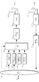
- FIG. 2 is a block diagram illustrating a first base station apparatus according to the first embodiment.
- the first base station apparatus includes an upper layer 101, a data channel generation unit 102, a control channel generation unit 103, a control signal generation unit 104, a reference signal generation unit 105, a resource mapping unit 106, a transmission signal generation unit 107, and a transmission unit 108.
- Transmission antenna units 109-1 to 109-NT Transmission antenna units 109-1 to 109-NT, reception antenna units 121-1 to 121-NR, a reception unit 122, and a control signal detection unit 123.
- NT is the number of transmitting antennas
- NR is the number of receiving antennas.
- the upper layer 101 is connected to the second base station apparatus via the backhaul line 10.
- a chip control circuit (not shown) for controlling each functional block is provided.
- the uplink signal includes an uplink data channel, a control channel, and a reference signal.
- the data channel is a channel used for transmitting uplink user data.
- an uplink common channel (PUSCH) can be used in LTE-A.
- the control channel includes a signal (Channel Statement Information) indicating a measurement result of a neighboring base station.
- the control channel includes a signal (Channel Quality Control) for notifying downlink reception quality, a scheduling allocation request signal, and the like.
- a signal Choannel Quality Control
- PUCCH Physical Uplink Control Channel
- measurement reports or the like can be used in LTE-A.
- control channel includes a random access channel.
- the random access channel is used when the terminal apparatus establishes a connection with a cell by initial access or handover.
- the reference signal is used for uplink propagation path estimation, symbol timing synchronization, reception quality measurement, and the like.
- the reference signal may be CRS, CSI-RS (Channel State Information-Reference Signal), DMRS (Demodulation Reference Signal), SRS (Sounding Reference Signal), etc. in LTE and LTE-A.
- the receiving unit 122 down-converts (radio frequency conversion) the signal received by the antenna 121 to a frequency band in which digital signal processing such as signal detection processing can be performed, and further performs filtering processing to remove spurious signals. Conversion from analog signal to digital signal (Analog to Digital conversion).
- the control signal detection unit 123 performs demodulation processing, decoding processing, and the like on the signal output from the reception unit 122. Thereby, the above-mentioned various signals (uplink data channel, uplink control channel, etc.) can be acquired from the uplink signal.
- the upper layer 101 generates information data (transport block, codeword) for the terminal device and outputs the information data to the data channel generation unit 102.
- the information data can be a unit for performing error correction coding processing.
- the information data can be a unit for performing retransmission control such as HARQ (Hybrid Automatic Repeat reQuest).
- the first base station device can transmit a plurality of information data to the terminal device.
- the upper layer is a layer of functions higher than the physical layer (Physical Layer) among the layers of communication functions defined in the OSI reference model, for example, a data link layer, a network layer, and the like.
- the upper layer 101 acquires a signal for notifying the downlink reception quality and the scheduling assignment request signal from the control signal detection unit 123.
- the upper layer 101 performs data channel scheduling based on the signal notifying the downlink reception quality and the scheduling assignment request signal.
- Scheduling refers to determining resource elements that map data channels and / or control channels and / or reference signals.
- a resource element is a minimum unit for arranging a signal. In OFDM transmission, a resource element is a unit for arranging a signal composed of one subcarrier and one OFDM symbol.
- the higher layer 101 notifies the control channel generation unit 103 of a base station apparatus candidate that is the next connection destination of the terminal apparatus connected to the first base station apparatus. For example, the cell ID of the base station apparatus candidate is notified.
- the upper layer 101 acquires the measurement result of the surrounding base station from the control signal detection unit 123.
- the upper layer 101 determines a base station device (target base station device) that is a connection destination of the terminal device, using the peripheral base station measurement result and other signals related to radio resource management.
- the upper layer requests a determination as to whether or not connection to the target base station apparatus is possible via the backhaul line 10 (connection request).
- the upper layer 101 obtains connection permission and system information of the target base station device from the target base station device that has requested connection through the backhaul line 10.
- the system information includes the number of transmission antennas of the target base station apparatus, the system bandwidth, and the system frame number.
- the system information can include broadcast information of the target base station device. For example, in LTE-A, MIB (Master Information) Block) can be used. Further, the system information may include the number of receiving antennas of the target base station apparatus.
- the upper layer 101 can hold information such as the number of transmission antennas, the system bandwidth, and the system frame number received from the target base station apparatus.
- the upper layer 101 notifies the target base station apparatus of terminal information of the connected terminal apparatus, unreachable packets, and the like through the backhaul line 10.
- the data channel generation unit 102 (data channel region allocation unit, data channel mapping unit, shared channel generation unit) performs adaptive control on the information data output from the upper layer 101 and performs data channel (shared channel, shared channel) for the terminal.
- the adaptive control in the data channel generation unit 102 includes an encoding process for performing error correction encoding, a scramble process for applying a scramble code unique to the terminal, and a multilevel modulation scheme (BPSK, QPSK, QAM). Etc.) and a layer mapping process for performing spatial multiplexing such as MIMO.
- the layer mapping process in the data channel generation unit 102 maps to one or more layers (streams) based on the number of ranks set for the terminal.
- the control channel generation unit 103 generates a downlink control channel.
- the downlink control channel includes downlink control information (DCI; Downlink Control Information).
- Downlink control information includes information on data channel resource allocation, MCS (Modulation and Coding scheme), information on spatial multiplexing (eg, RI; Rank Indicator), and scrambling identity (also referred to as scrambling link identifier).
- Information, information on a reference signal sequence identity also referred to as a base sequence identity, a base sequence identifier, and a base sequence index
- a reference signal sequence identity also referred to as a base sequence identity, a base sequence identifier, and a base sequence index
- the downlink control channel includes a signal (peripheral base station measurement control) indicating that the connected terminal apparatus requests measurement of communication quality between the peripheral base station apparatus and the terminal apparatus.
- the peripheral base station measurement control can include the cell ID of the target base station candidate notified from the higher layer 101.
- the downlink control channel includes information for instructing connection to the target base station apparatus notified from the higher layer 101.
- the information instructing the connection can include a cell ID of the target base station device.
- the downlink control channel includes system information of the target base station apparatus notified from the higher layer 101.
- the control channel generation unit 103 performs data modulation processing and precoding processing on the downlink control channel.
- the control channel generation unit 103 includes broadcast information of the first base station apparatus (for example, LTE PBCH; Physical Broadcast Channel).
- the control signal generation unit 104 generates a synchronization signal for establishing and following the synchronization between the first base station apparatus and the terminal apparatus such as symbol synchronization and frame synchronization.
- a synchronization signal LTE, LTE-A PSS (Primary Synchronization Signal), SSS (Secondary Synchronization Signal) can be used.
- the reference signal generation unit 105 generates a reference signal (pilot signal) and outputs the reference signal to the resource mapping unit 106.
- the reference signal is a signal used by each mobile station apparatus to estimate the communication quality between the base station apparatus and the base station apparatus that transmits the reference signal. Communication quality includes propagation path, received power, interference power, received SNR (Signal to Noise power Ratio), received SINR (Signal to Interference and Noise power Ratio), etc. is there.
- the resource mapping unit 106 is a data channel / control channel generation unit that the data channel generation unit 102 outputs based on the resource allocation (scheduling information) of the data channel, control channel, control signal, and reference signal notified from the upper layer 101
- the control channel output from 103, the control signal output from the control signal generation unit 104, and the reference signal output from the reference signal generation unit 105 are allocated to resource elements.
- the transmission signal generation unit 107 generates an OFDM signal. Specifically, an inverse discrete Fourier transform (IDFT) is performed on the frequency domain signal input from the resource mapping unit 106 to convert it into a time domain signal.
- the transmission signal generation unit 107 adds an GI (Guard Interval; also referred to as a guard interval or guard interval) to the time domain signal (referred to as an effective symbol) to generate an OFDM symbol.
- the GI is a section added for the purpose of preventing the OFDM symbols of the preceding and succeeding times from interfering with each other.
- the GI is, for example, CP (Cyclic Prefix).
- the GI insertion unit 110 prepends a copy of a part of the latter half of the valid symbol as a GI to the valid symbol. Therefore, an effective symbol preceded by GI is an OFDM symbol.
- the transmitting unit 108 performs D / A (digital-to-analog) conversion on the OFDM symbol to generate an analog signal.
- the transmission unit 108 generates a band limited signal by band-limiting the generated analog signal by filtering processing.
- Transmitting section 108 up-converts the generated band limited signal into a radio frequency band, and outputs it to transmitting antenna sections 109-1 through 109-NT.
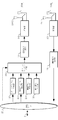
- FIG. 3 is a block diagram illustrating a second base station apparatus according to the first embodiment.
- the second base station apparatus includes an upper layer 151, a data channel generation unit 152, a control channel generation unit 153, a control signal generation unit 154, a reference signal generation unit 155, a resource mapping unit 156, a transmission signal generation unit 157, and a transmission unit 158.
- a chip control circuit (not shown) for controlling each functional block is provided.
- the upper layer 151 can be connected to the first base station apparatus and the other second base station apparatus through the backhaul line 10.
- the receiving unit 172 down-converts (radio frequency conversion) the signal received by the antenna 171-x into a frequency band in which digital signal processing such as signal detection processing can be performed, and performs filtering processing to remove spurious and perform filtering processing.
- the signal is converted from an analog signal to a digital signal (Analog to Digital conversion).
- the control signal detection unit 173 performs demodulation processing, decoding processing, and the like on the signal output from the reception unit 172. As a result, various signals (uplink, uplink data channel, etc.) included in the uplink signal can be acquired.
- the upper layer 151 includes a function of determining whether or not connection is permitted in response to a connection request from the first base station apparatus through the backhaul line 10.
- the upper layer 151 can generate system information to be notified to the terminal device.
- the system information includes the number of transmission antennas of the target base station apparatus, the system bandwidth, and the system frame number. For example, in LTE-A, MIB (Master Information Block) can be used. Further, the system information may include the number of receiving antennas of the target base station apparatus.
- the upper layer 151 can notify the first base station apparatus of the connection permission and the system information through the backhaul line 10.
- the upper layer 151 can acquire terminal information and unreachable packets of the terminal devices connected to the own base station device from the first base station device through the backhaul line 10.
- the upper layer 151 generates information data (transport block, codeword) for the terminal device and outputs the information data to the data channel generation unit 152.
- the upper layer 151 notifies the control channel generation unit 153 of downlink control information used by the control channel generation unit 153 for control channel generation.
- the data channel generation unit 152 performs adaptive control on the information data output from the upper layer 151 and generates a data channel for the terminal.
- the control channel generation unit 153 generates a downlink control channel.
- the downlink control channel includes downlink control information (DCI; Downlink Control Information).
- Downlink control information includes information on data channel resource allocation, MCS (Modulation and Coding scheme), information on spatial multiplexing number (RI), information on scrambling identity (also called scrambling link identifier), reference signal sequence Information on the identity (also referred to as a base sequence identity, a base sequence identifier, and a base sequence index) is included.
- the control channel generation unit 153 performs data modulation processing and precoding processing on the downlink control channel.
- the resource mapping unit 156 is configured to output the data channel, control channel generation unit, and data channel output from the data channel generation unit 152 based on the resource allocation (scheduling information) of the data channel, control channel, control signal, and reference signal notified from the higher layer 151.
- the control channel output by 153, the control signal output by control signal generation section 154, and the reference signal output by reference signal generation section 155 are allocated to resource elements.
- the control signal generation unit 154 can generate a synchronization signal for establishing and following the synchronization between the second base station apparatus and the terminal apparatus such as symbol synchronization and frame synchronization.
- the reference signal generation unit 155 generates a reference signal (pilot signal) and outputs the reference signal to the resource mapping unit 156.
- the transmission signal generation unit 157 generates an OFDM signal from the signal input from the resource mapping unit 156.
- the transmission unit 158 D / A converts the OFDM symbol to generate an analog signal.
- the transmission unit 158 generates a band limited signal by band-limiting the generated analog signal by filtering processing. Transmitting section 158 upconverts the generated band limited signal to a radio frequency band and outputs it to transmitting antenna sections 159-1 through 159-NT.
- the control channel transmitted by the second base station apparatus can be reduced. Specifically, control information transmitted on the downlink control channel can be reduced. In addition, control information transmitted through the broadcast channel can be reduced. For this reason, it is possible to avoid complicated control of connection and switching between the base station device and the terminal device for a plurality of base station devices arranged to overlap the cell of the first base station device. .
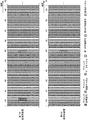
- FIG. 4 shows an aspect of a transmission frame format in the communication system according to the first embodiment.
- one transmission frame format is composed of 10 subframes (# 0 to # 9).
- the 4 is a transmission frame format in the downlink of the first base station apparatus.
- the upper layer 101 of the first base station apparatus notifies the resource mapping unit 106 of scheduling information according to the upper format of FIG.
- the resource mapping unit 106 of the first base station apparatus according to the scheduling information, the data channel output from the data channel generation unit 102, the downlink control channel output from the control channel generation unit 103, the broadcast channel, and the control signal generation unit
- the synchronization signal output from 104 and the reference signal output from the reference signal generation unit 105 can be assigned to resource elements.
- FIG. 4 is a transmission frame format in the downlink of the second base station apparatus.
- Upper layer 151 of the second base station apparatus notifies scheduling information to resource mapping section 156 according to the lower format of FIG.
- the resource mapping unit 156 of the second base station apparatus outputs the data channel output from the data channel generation unit 102, the downlink control channel output from the control channel generation unit 103, and the control signal generation unit 104 according to the scheduling information.
- the reference signal output from the reference signal generation unit 105 can be assigned to resource elements.
- mapping of the broadcast channel can be omitted in the second base station apparatus. For this reason, many radio
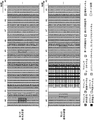
- FIG. 5 shows another aspect of the transmission frame format of the communication system in the first embodiment.
- FIG. 5 shows a case where the second base station apparatus performs uplink and downlink communication with a terminal apparatus connected to the base station apparatus using TDD (Time Division Duplex, time division duplex).
- TDD Time Division Duplex, time division duplex
- one transmission frame format is composed of 10 subframes (# 0 to # 9).
- the upper part of FIG. 5 shows a transmission frame format in the downlink of the first base station apparatus.
- the upper part of FIG. 5 is a downlink transmission frame format of FDD (Frequency Division Duplex, Frequency Division Duplex).
- the upper part of FIG. 5 has the same format as that of the upper part of FIG. 4, and the resource mapping unit 106 of the first base station apparatus performs resource mapping in the same manner as described for the upper part of FIG.
- the lower part of FIG. 5 shows the transmission frame format of the second base station apparatus.
- subframe indexes # 0 and # 4 to # 9 are subframes to which downlink signals are mapped.
- Subframe indexes # 3 and # 4 are subframes to which uplink signals are mapped.
- the subframe index # 2 is a subframe (also referred to as a special subframe) having a guard interval in order to prevent complication at the time of switching from uplink to downlink.
- the upper layer 151 of the second base station apparatus notifies the scheduling information to the resource mapping unit 156 according to the lower format of FIG.
- the resource mapping unit 156 of the second base station apparatus includes the downlink data channel output from the data channel generation unit 102, the downlink control channel output from the control channel generation unit 103, and the control signal generation unit 104 according to the scheduling information.
- the synchronization signal to be output and the downlink reference signal output from the reference signal generation unit 105 can be assigned to the resource element.
- mapping of the broadcast channel can be omitted in the second base station apparatus. For this reason, many radio
- FDD transmission method
- FIG. 6 is a block diagram illustrating the terminal device according to the first embodiment.
- the terminal apparatus includes reception antenna units 201-1 to 201-NR, reception unit 202, reception signal processing unit 203, propagation path estimation unit 204, control channel processing unit 205, data channel processing unit 206, synchronization unit 207, and upper layer 210. , Transmission antenna units 221-1 to 221-NT, a transmission unit 222, a transmission signal generation unit 223, a data channel generation unit 224, a control channel generation unit 225, and a reference signal generation unit 226.
- a part or all of the terminal device is formed into a chip to form an integrated circuit, it has a chip control circuit (not shown) that controls each functional block.
- Receiving antenna units 201-1 to 201-NR receive a carrier band OFDM signal propagated as a radio wave from the first base station device or the second base station device, and receive the received carrier band OFDM signal to receiving unit 202. Output.
- the terminal apparatus can be provided with receiving antenna units 201-1 to 201-NR each capable of corresponding to the frequency band.
- the receiving unit 202 down-converts the OFDM signals input from the receiving antenna units 201-1 to 201-NR into a frequency band where digital signal processing is possible, and further performs filtering processing on the down-converted signal to remove unnecessary components (spurious signals). Spurious);
- the receiving unit 202 converts the filtered signal from an analog signal to a digital signal (A / D; Analog-to-Digital), and outputs the converted digital signal to the received signal processing unit 203 and the synchronization unit 207.
- the synchronization unit 207 establishes symbol synchronization and frame synchronization for signals transmitted from the first base station apparatus and the second base station apparatus, using a synchronization signal (eg, PSS, SSS) included in the input signal. To do.
- the received signal processing unit 203 performs OFDM modulation decoding processing on the digital signal input from the receiving unit 202 according to the symbol synchronization timing and frame synchronization timing input from the synchronization unit 207. Specifically, GI length removal and DFT (IFFT) processing are performed.
- the propagation path estimation unit 204 performs propagation path estimation using a downlink reference signal included in the signal output from the reception signal processing unit 203.
- the propagation path estimation value is input to the control channel processing unit 205, the data channel processing unit 206, and the upper layer 210.
- the propagation path estimated value is, for example, a transfer function or an impulse response.
- the propagation path estimation unit 204 measures the channel quality between the terminal device and the first base station device or the second base station device using the downlink reference signal included in the signal output from the received signal processing unit 203. (Channel state measurement). For example, the channel quality corresponds to received power, interference power, received SNR, received SINR, and the like.
- the control channel processing unit 205 detects a downlink control channel (for example, PDCCH, radio resource control (RRC) signaling, etc.) included in the signal output from the received signal processing unit 203 (propagation based on the channel estimation value). Path compensation, demodulation processing, and decoding processing).
- a downlink control channel for example, PDCCH, radio resource control (RRC) signaling, etc.
- RRC radio resource control
- control channel processing unit 205 When the control channel processing unit 205 extracts a signal related to measurement control of neighboring base stations included in the downlink control channel, it notifies the higher layer 210. When the control channel processing unit 205 extracts a signal related to the connection instruction included in the downlink control channel, the control channel processing unit 205 notifies the upper layer 210 of the extracted signal. When the control channel processing unit 205 extracts the system information related to the second base station device included in the downlink control channel, the control channel processing unit 205 notifies the higher layer 210 of it. When the control channel processing unit 205 extracts uplink data channel control information such as MCS and scheduling assignment applied to the uplink data channel included in the downlink control channel, the control channel processing unit 205 notifies the upper layer 210 of the extracted information.
- uplink data channel control information such as MCS and scheduling assignment applied to the uplink data channel included in the downlink control channel
- the data channel processing unit 206 performs detection of a downlink data channel included in the signal output from the reception signal processing unit 203 (propagation compensation, demodulation processing, and decoding processing based on the channel estimation value) Input to layer 210.
- the upper layer 210 selects a base station device to be connected from the channel state between the terminal device and the peripheral base station device input from the propagation path estimation unit 204, and transmits the result (peripheral base station measurement result) as a transmission signal generation unit. 223 can be input.
- the upper layer 210 extracts information data from the downlink data channel input from the data channel processing unit 206.
- the data channel generation unit 224 performs adaptive control (error correction coding, data modulation, etc.) on the information data output from the higher layer 210, and a data channel (for example, PUSCH; Physical Uplink Shared Channel) for the base station apparatus Is generated.
- adaptive control error correction coding, data modulation, etc.
- the control channel generation unit 225 generates an uplink control channel.
- the uplink control channel includes the surrounding base station assumption result.
- the control channel generation unit 225 generates a random access channel used for uplink synchronization.
- the reference signal generation unit 226 generates a reference signal (for example, DMRS, SRS) used for reception quality measurement necessary for applying uplink channel estimation and frequency scheduling.
- the transmission signal generation unit 223 performs resource mapping on the uplink data channel, the uplink control channel, the random access channel, and the reference signal according to the uplink transmission format, and performs multi-carrier modulation (SC-FDMA, OFDM) and the like, and an uplink transmission signal is generated.
- SC-FDMA multi-carrier modulation
- the output signal of the control signal generation unit 223 is up-converted by the transmission unit 222 to a frequency band that can be transmitted in the uplink, and is transmitted to the base station apparatus via the transmission antenna units 221-1 to 221-NT.
- terminal 200 when power is turned on, terminal 200 performs a cell search for a connected base station apparatus.
- terminal 200 searches for a base station apparatus to be connected from among the first base station apparatuses.
- Terminal apparatus 200 performs a cell search using a synchronization sequence (synchronization channel) generated based on the cell ID assigned to the first base station apparatus.
- the terminal device 200 searches for a base station device connected from the first base station device by performing a cell search only on the frequency band of the first base station device.
- the first base station apparatus and the second base station are configured by assigning synchronization channels to different resource elements in the first base station apparatus and the second base station apparatus. Can be distinguished from the device.
- the terminal device performs cell research on the base station device to be connected by the resource allocation of the synchronization channel in the first base station device.
- the terminal device 200 receives the broadcast channel of the selected first base station device and establishes a connection with the first base station device.
- the base station device 100-1 is selected by the cell search, and the connection is established.
- base station apparatus 100-1 switches the connection to the second base station apparatus.
- FIG. 7 is a sequence diagram in which the terminal device in the communication system according to the first embodiment connects to the second base station device.
- FIG. 7 shows a case where the terminal device connected to the first base station device switches connection to the second base station device.
- the source base station apparatus is a connection source base station apparatus
- the target base station apparatus is a connection destination base station apparatus.
- the terminal device 200 When receiving a notification of control of neighboring base stations from the base station device 100-1 that is the source base station device (S201), the terminal device 200 measures the channel state between the base station device designated by the notification and its own station. (S202). In FIG. 1, the terminal device 200 measures the channel state between the own station and the base station devices 100-2 to 100-5.
- a reference signal transmitted from each base station apparatus can be used. For example, CRS, SRS, and CSI-RS in LTE can be used.
- the terminal device 200 notifies the base station device 100-1 of the channel state measurement result (peripheral base station measurement result) (S203).
- the base station apparatus 100-1 can determine the connection destination (target base station apparatus) based on the measurement results of the neighboring base stations, the resource allocation status of the terminal apparatus, and the like (S204).
- the source base station apparatus desirably selects a base station apparatus with good channel quality as the target base station apparatus.
- the channel quality can be determined from received power, interference power, received SNR, received SINR, and the like.
- base station apparatus 100-1 selects base station apparatus 100-3 as the target base station apparatus.
- the base station apparatus 100-1 notifies a connection request (for example, a handover request) to the base station apparatus 100-3 through the backhaul line 10 (S205).
- the base station device 100-3 determines whether or not connection is possible (S206). If connection is possible, preparation for connection such as scheduling is performed (S206).
- the base station 100-3 notifies the base station apparatus 100-1 of permission notification (handover request ACK / NACK) and system information (S207).
- the system information includes the system bandwidth of the base station device 100-3, the system frame number, and the number of transmission antennas. As the system information, information notified by MIB can be used.
- the base station device 100-1 When receiving the permission notification, the base station device 100-1 instructs the terminal device 200 to switch the connection to the base station device 100-3 (S208). Also, the base station apparatus 100-1 notifies the terminal apparatus 200 of the system information of the base station apparatus 100-3 (S209).
- the notification of the system information in S207 can be omitted. For example, it can be omitted when the target base station apparatus requested by the first base station apparatus for connection (S205) has been selected as the target base station apparatus in the past.
- the terminal device 200 Upon receiving the connection instruction and system information notification (S208, S209), the terminal device 200 performs transmission destination switching, and performs synchronization processing with the base station device 100-3 using a random access channel (S211). ). The terminal device 200 then notifies the base station device 100-3 that the switching has been completed (notification that the connection has been established), and transmits a data channel (information data) (S212).
- the terminal device connected to the first base station device changes connection to the second base station device, broadcast information can be reduced. Thereby, the utilization efficiency of a radio
- the terminal apparatus connected to the second base station apparatus is the second Another mode of connecting / switching to the base station apparatus will be described.
- FIG. 8 is a sequence diagram in which the terminal device in the communication system according to the second embodiment connects to the second base station device.
- terminal apparatus 200 is wirelessly connected to base station apparatus 100-3 belonging to the second base station apparatus.
- the base station device 100-3 becomes the source base station device.
- the base station device 100-3 When switching the connection destination of the terminal device 200, the base station device 100-3 makes a connection switching request to the base station device 100-1 (master base station device) which is the first base station device (S301). For example.
- the base station apparatus 100-3 continuously receives a NACK signal for requesting retransmission in the downlink from the terminal apparatus 200 or an error in the uplink data channel from the terminal apparatus 200 increases, the base station apparatus 100-3 requests connection switching I do. Further, the terminal device 200 can request connection to the source base station device. Also, the base station apparatus 100-3 can notify the terminal apparatus 200 that the connection switching request has been made (S302).
- the terminal device 200 When the terminal device 200 receives a neighboring base station measurement control notification from the base station device 100-1 that has received the connection switching request (S301) (S303), the base station device (target base station device candidate) designated by the notification The channel state between the mobile station and the own station is measured (S304).
- the terminal device 200 measures channel states between the own station and the base station device 100-2, between the own station and the base station device 100-4, and between the own station and the base station device 100-5.
- the base station apparatus 100-1 may be included in the target base station apparatus candidates.
- a reference signal transmitted from each base station apparatus can be used.
- CRS, SRS, and CSI-RS in LTE can be used.
- the terminal device 200 notifies the base station device 100-1 of the channel state measurement result (peripheral base station measurement result) (S305).
- the base station device 100-1 can determine the connection destination based on the measurement results of the neighboring base stations, the resource allocation status of the terminal device, and the like (S306).
- the source base station apparatus desirably selects a base station apparatus with good channel quality as the target base station apparatus.
- base station apparatus 100-1 selects base station apparatus 100-2 as the target base station apparatus. That is, the second base station apparatus (target base station apparatus) in FIG. 8 becomes the base station apparatus 100-2.
- the base station apparatus 100-1 notifies a connection request (for example, a handover request) to the base station apparatus 100-2 through the backhaul line 10 (S307).
- the base station apparatus 100-2 determines whether or not connection is possible (S308). If connection is possible, preparation for connection such as scheduling is performed (S309).
- the base station 100-3 notifies the base station apparatus 100-1 of permission notification (handover request ACK / NACK) and system information (S309).
- the system information includes the system bandwidth of the base station apparatus 100-2, the system frame number, and the number of transmission antennas. As the system information, information notified by MIB can be used.
- the notification of the system information in S309 can be omitted.
- the target base station apparatus requested by the first base station apparatus for connection (S307) has been selected as the target base station apparatus in the past.
- the base station device 100-1 When receiving the permission notification, the base station device 100-1 notifies the base station device 100-3 of the permission (S310). In addition, the base station device 100-1 issues a connection instruction to the terminal device 200 to switch the connection to the base station device 100-2 (S311). Also, the base station apparatus 100-1 notifies the terminal apparatus 200 of the system information of the base station apparatus 100-2 (S312).
- the base station device 100-3 notifies the base station device 100-2 of the terminal information of the terminal device 200, the unreachable packet, etc. (S313).
- the terminal device 200 Upon receiving the connection instruction and system information notification (S311 and S312), the terminal device 200 performs transmission destination switching and performs synchronization processing using the random access channel for the base station device 100-2 (S314).
- the terminal device 200 then notifies the base station device 100-3 that the switching has been completed (notification that the connection has been established), and transmits a data channel (information data) (S315).
- the first base station apparatus in the second embodiment can have the same configuration as that in FIG.
- the upper layer 101 of the first base station apparatus in the second embodiment can have a function of transferring a permission notice (S310) to the second base station apparatus through the backhaul line 10.
- the 2nd base station apparatus in 2nd Embodiment can be equipped with the structure similar to FIG.
- the upper layer 151 of the second base station apparatus in the second embodiment may notify terminal information, unreachable packet information, etc. to another second base station apparatus through the backhaul line 10 (S313). it can.
- the upper layer 151 of the second base station apparatus in the second embodiment can include information (S302) for notifying that the connection has been switched to the downlink control channel.
- the upper layer 151 of the second base station apparatus in the second embodiment performs frequency base station measurement transmitted by the first base station apparatus (master base station apparatus) in the notification that the connection has been switched (S302).
- the transmission timing information of control (S303) can be included in the downlink control channel.
- the terminal device in the second embodiment can have the same configuration as in FIG.
- the control channel processing unit 205 of the terminal device in the second embodiment can extract information notifying that the connection has been switched and transmission timing information of frequency base station measurement control, and can notify the higher layer 210 of the information.
- the control channel processing unit 205 of the terminal device in the second embodiment can extract the frequency base station measurement control transmitted by the first base station device based on the transmission timing information of the frequency base station measurement control. .
- the first base station apparatus in the second embodiment is based on the transmission frame format in the upper part of FIG. 4 and the upper part of FIG. 5, and the downlink data channel, downlink control channel, broadcast channel, downlink synchronization signal, downlink Resource mapping can be performed on the link reference signal.
- the second base station apparatus according to the second embodiment is based on the transmission frame format in the lower part of FIG. 4 and the lower part of FIG. 5, and the downlink data channel, the downlink control channel, the downlink synchronization signal, and the downlink reference signal. Can be resource mapped.
- the second embodiment in the communication system in which a plurality of second base station devices are arranged so that the entire range or part of the connectable range of the first base station device overlaps with the base station device.
- the terminal device connected to the second base station device changes connection to another second base station device, the broadcast information can be reduced. Thereby, the utilization efficiency of a radio
- the terminal device can connect the plurality of second base station devices with low delay.
- the second base station apparatus (target base station apparatus) in FIG. 8 sends a permission notice (S309, S310) to the second base station apparatus (source base station apparatus) via the backhaul line 10. ) Directly.
- the terminal device can switch the connection between the second base station devices with even lower delay.
- the terminal device it is possible to control the terminal device to be connected to the second base station device only after the terminal device is initially connected to the first base station device.
- the synchronization signal (first synchronization signal, second synchronization signal) can be omitted in the transmission frame of the second base station apparatus in the lower part of FIG. 4 and the lower part of FIG.
- the first base station apparatus can notify the synchronization timing between the second base station apparatus and the terminal apparatus in S208 or S209 of FIG.
- the first base station apparatus can notify the synchronization timing between the second base station apparatus and the terminal apparatus in S311 or S312 of FIG.
- the first base station apparatus can notify the synchronization timing of the second base station apparatus based on the synchronization timing of the first base station apparatus.
- the notification of the synchronization timing can be included in a downlink control channel.
- the terminal device can perform downlink frame synchronization, symbol synchronization acquisition, and fine adjustment based on the notification of the synchronization timing.
- the synchronization unit 207 of the terminal device can perform synchronization processing based on the back synchronization timing notification.
- the program that operates in the terminal device or base station device related to the present invention is a program that controls the CPU or the like (a program that causes a computer to function) so as to realize the functions of the above-described embodiments related to the present invention.
- Information handled by these devices is temporarily stored in the RAM at the time of processing, then stored in various ROMs and HDDs, read out by the CPU, and corrected and written as necessary.
- a recording medium for storing the program a semiconductor medium (for example, ROM, nonvolatile memory card, etc.), an optical recording medium (for example, DVD, MO, MD, CD, BD, etc.), a magnetic recording medium (for example, magnetic tape, Any of a flexible disk etc. may be sufficient.
- the processing is performed in cooperation with the operating system or other application programs.
- the functions of the invention may be realized.
- the program when distributing to the market, can be stored and distributed on a portable recording medium, or transferred to a server computer connected via a network such as the Internet.
- the storage device of the server computer is also included in the present invention.
- Each functional block of the receiving apparatus may be individually formed as a chip, or a part or all of them may be integrated into a chip. When each functional block is integrated, an integrated circuit control unit for controlling them is added.
- the method of circuit integration is not limited to LSI, and may be realized by a dedicated circuit or a general-purpose processor.
- an integrated circuit based on the technology can also be used.
- the terminal device of the present invention is not limited to application to a mobile station device, but is a stationary or non-movable electronic device installed indoors or outdoors, such as an AV device, a kitchen device, a cleaning / cleaning device, etc. Needless to say, it can be applied to laundry equipment, air conditioning equipment, office equipment, vending machines, and other daily life equipment.
- the present invention is suitable for use in communication systems, communication methods, base station apparatuses, and mobile station apparatuses.
Landscapes
- Engineering & Computer Science (AREA)
- Signal Processing (AREA)
- Computer Networks & Wireless Communication (AREA)
- Computer Security & Cryptography (AREA)
- Mobile Radio Communication Systems (AREA)
Abstract
Description
周辺基地局測定結果から前記端末装置の接続先を決定する上位レイヤを備え、
前記上位レイヤは、接続先と決定した第2の基地局装置のシステム情報を該第2の基地局装置から取得することを特徴とする。
本発明に係る実施形態における通信システムは、複数の基地局装置と複数の端末装置を備える。
図1は、第1の実施形態における異なるセル半径の複数の基地局装置を配置した下りリンクにおける通信システムの一例を示す概略図である。
第1の基地局装置は、上位レイヤ101、データチャネル生成部102、制御チャネル生成部103、制御信号生成部104、参照信号生成部105、リソースマッピング部106、送信信号生成部107、送信部108、送信アンテナ部109-1乃至109-NT、受信アンテナ部121-1乃至121-NR、受信部122、制御信号検出部123を備えて構成される。NTは送信アンテナ数、NRは受信アンテナ数である。また、上位レイヤ101は、第2の基地局装置とバックホール回線10で接続されている。なお、上記第1の基地局装置の一部或いは全部をチップ化して集積回路となる場合、各機能ブロックに対して制御を行なうチップ制御回路(図示せず)を有する。
前記データチャネルは、上りリンクのユーザデータを送信するために使用されるチャネルである。前期データチャネルは、例えば、LTE-Aでは上りリンク共通チャネル(PUSCH;Phisical Uplink Shared CHannel)を用いることができる。
Block)を用いることができる。また、前記システム情報にターゲット基地局装置の受信アンテナ数を含むことができる。
下りリンク制御チャネルには、上位レイヤ101から通知されるターゲット基地局装置のシステム情報が含まれる。
制御チャネル生成部103は、前記下りリンク制御チャネルに対してデータ変調処理、プレコーディング処理を行う。
第2の基地局装置は、上位レイヤ151、データチャネル生成部152、制御チャネル生成部153、制御信号生成部154、参照信号生成部155、リソースマッピング部156、送信信号生成部157、送信部158、送信アンテナ部159-1乃至159-NT、受信アンテナ部171-1乃至171-NR、受信部172、制御信号検出部173を備えて構成される。なお、第2の基地局装置の一部あるいは全部をチップ化して集積回路となる場合、各機能ブロックに対して制御を行なうチップ制御回路(図示せず)を有する。また、上位レイヤ151は、バックホール回線10を通じて、第1の基地局装置及び他の第2の基地局装置と接続することができる。
第2の基地局装置のリソースマッピング部156は、前記スケジューリング情報にしたがい、データチャネル生成部102が出力する下りデータチャネル、制御チャネル生成部103が出力する下りリンク制御チャネル、制御信号生成部104が出力する同期信号、及び参照信号生成部105が出力する下り参照信号をリソースエレメントに割り当てることができる。
基地局装置100-1は、周辺基地局測定結果、端末装置のリソース割当状況などに基づいて、接続先(ターゲット基地局装置)を決定することができる(S204)。ソース基地局装置は、チャネル品質が良い基地局装置をターゲット基地局装置と選定することが望ましい。前記チャネル品質は、受信電力、干渉電力、受信SNR、受信SINRなどにより判断することができる。ここで、基地局装置100-1は、ターゲット基地局装置として、基地局装置100-3を選択したとする。
第2の実施形態では、第1の基地局装置のセルと重複するように第2の基地局装置が配置された通信システムにおいて、第2の基地局装置に接続している端末装置が第2の基地局装置に接続・切替を行う別の態様を説明する。
これによれば、端末装置はさらに低遅延で第2の基地局装置間の接続切替をすることができる。
100-1 第1の基地局装置
100-2、100-3、100-4、100-5 第2の基地局装置
101 上位レイヤ
102 データチャネル生成部
103 制御チャネル生成部
104 制御信号生成部
105 参照信号生成部
106 リソースマッピング部
107 送信信号生成部
108 送信部
109―NT 送信アンテナ部
121-NR 受信アンテナ部
122 受信部
123 制御信号検出部
151 上位レイヤ
152 データチャネル生成部
153 制御チャネル生成部
153 制御チャネル生成部
154 制御信号生成部
155 参照信号生成部
156 リソースマッピング部
157 送信信号生成部
158 送信部
159-NT 送信アンテナ部
171-NR 受信アンテナ部
172 受信部
173 制御信号検出部
200 端末装置
201―NR 受信アンテナ部
202 受信部
203 受信信号処理部
204 伝搬路推定部
205 制御チャネル処理部
206 データチャネル処理部
210 上位レイヤ
221-NT 送信アンテナ部
222 送信部
223 送信信号生成部
224 データチャネル生成部
225 制御チャネル生成部
226 参照信号生成部
Claims (14)
- 第1の基地局装置と前記第1の基地局装置のセル範囲と重複するように配置された複数の第2の基地局装置と前記第1の基地局装置又は前記第2の基地局装置と接続する端末装置を備える通信システムの第1の基地局装置であって、
第1の基地局装置の報知情報を通知する報知チャネルと、第2の基地局装置のシステム情報を通知する無線リソース制御信号を含む下りリンクチャネルを送信する送信部を備えること、
を特徴とする基地局装置。 - 前記第2の基地局装置のシステム情報は第2の基地局装置の報知情報であること、
を特徴とする請求項1に記載の基地局装置。 - 前記第2の基地局装置のシステム情報は第2の基地局装置の送信アンテナ数であること、
を特徴とする請求項1に記載の基地局装置。 - 前記第2の基地局装置のシステム情報は第2の基地局装置のシステム帯域幅であること、
を特徴とする請求項1に記載の基地局装置。 - 前記第2の基地局装置のシステム情報は第2の基地局装置のシステムフレーム番号であること、
を特徴とする請求項1に記載の基地局装置。 - 前記第1の基地局装置は、
周辺基地局測定結果から前記端末装置の接続先を決定する上位レイヤを備え、
前記上位レイヤは、接続先と決定した第2の基地局装置のシステム情報を該第2の基地局装置から取得すること、
を特徴とする請求項1に記載の基地局装置。 - 第1の基地局装置と前記第1の基地局装置のセル範囲と重複するように配置された複数の第2の基地局装置と前記第1の基地局装置又は前記第2の基地局装置と接続する端末装置を備える通信システムの第1の基地局装置の送信方法であって、
第1の基地局装置の報知情報を通知する報知チャネルと、第2の基地局装置のシステム情報を通知する無線リソース制御信号を含む下りリンクチャネルとを送信すること、
を特徴とする送信方法。 - 第1の基地局装置と前記第1の基地局装置のセル範囲と重複するように配置された複数の第2の基地局装置と前記第1の基地局装置又は前記第2の基地局装置と接続する端末装置を備える通信システムの端末装置であって、
第1の基地局装置の報知情報を通知する報知チャネルと、第2の基地局装置のシステム情報を通知する無線リソース制御信号を含む下りリンクチャネルを受信する受信部を備えること、
を特徴とする端末装置。 - 第1の基地局装置と前記第1の基地局装置のセル範囲と重複するように配置された複数の第2の基地局装置と前記第1の基地局装置又は前記第2の基地局装置と接続する端末装置を備える通信システムであって、
前記第1の基地局装置の送信部は、
第1の基地局装置の報知情報を通知する報知チャネルと、第2の基地局装置のシステム情報を通知する無線リソース制御信号を含む下りリンクチャネルを送信すること、
を特徴とする通信システム。 - 前記第1の基地局装置は、
参照信号、データチャネル、制御チャネル、報知チャネル及び同期信号を割り当てるスケジューリング情報に基づきリソースマッピングをするリソースマッピング部を備え、
前記第2の基地局装置は、
参照信号、データチャネル及び制御チャネルを割り当てるスケジューリング情報に基づきリソースマッピングをするリソースマッピング部を備えること、
を特徴とする請求項1に記載の通信システム。 - 前記第2の基地局装置は、
参照信号、データチャネル、制御チャネル及び同期信号を割り当てるスケジューリング情報に基づきリソースマッピングをするリソースマッピング部を備えること、
を特徴とする請求項10に記載の通信システム。 - 前記第1の基地局装置は、周波数分割複信を行うフレームフォーマットに基づきリソースマッピングするリソースマッピング部を備え、
前記第2の基地局装置は、時間分割複信を行うフレームフォーマットに基づきリソースマッピングするリソースマッピング部を備えること、
を特徴とする請求項10又は請求項11に記載の通信システム。 - 第1の基地局装置と前記第1の基地局装置のセル範囲と重複するように配置された複数の第2の基地局装置と前記第1の基地局装置又は前記第2の基地局装置と接続する端末装置の通信方法であって、
前記第1の基地局装置は、
第1の基地局装置の報知情報を通知する報知チャネルと、第2の基地局装置のシステム情報を通知する無線リソース制御信号を含む下りリンクチャネルを送信すること、
を特徴とする通信方法。 - 第1の基地局装置と前記第1の基地局装置のセル範囲と重複するように配置された複数の第2の基地局装置と前記第1の基地局装置又は前記第2の基地局装置と接続する端末装置を備える通信システムの第1の基地局装置の集積回路であって、
第1の基地局装置の報知情報を通知する報知チャネルと、第2の基地局装置のシステム情報を通知する無線リソース制御信号を含む下りリンクチャネルを送信する機能を有すること、
を特徴とする集積回路。
Priority Applications (2)
| Application Number | Priority Date | Filing Date | Title |
|---|---|---|---|
| US14/425,065 US20150223202A1 (en) | 2012-09-19 | 2013-08-27 | Base station device, terminal device, communication system, communication method, and integrated circuit |
| JP2014536708A JPWO2014045812A1 (ja) | 2012-09-19 | 2013-08-27 | 基地局装置、端末装置、通信システム、通信方法および集積回路 |
Applications Claiming Priority (2)
| Application Number | Priority Date | Filing Date | Title |
|---|---|---|---|
| JP2012205283 | 2012-09-19 | ||
| JP2012-205283 | 2012-09-19 |
Publications (1)
| Publication Number | Publication Date |
|---|---|
| WO2014045812A1 true WO2014045812A1 (ja) | 2014-03-27 |
Family
ID=50341135
Family Applications (1)
| Application Number | Title | Priority Date | Filing Date |
|---|---|---|---|
| PCT/JP2013/072829 Ceased WO2014045812A1 (ja) | 2012-09-19 | 2013-08-27 | 基地局装置、端末装置、通信システム、通信方法および集積回路 |
Country Status (3)
| Country | Link |
|---|---|
| US (1) | US20150223202A1 (ja) |
| JP (1) | JPWO2014045812A1 (ja) |
| WO (1) | WO2014045812A1 (ja) |
Cited By (1)
| Publication number | Priority date | Publication date | Assignee | Title |
|---|---|---|---|---|
| WO2025204178A1 (ja) * | 2024-03-27 | 2025-10-02 | パナソニックIpマネジメント株式会社 | 無線通信システム |
Families Citing this family (5)
| Publication number | Priority date | Publication date | Assignee | Title |
|---|---|---|---|---|
| WO2014069587A1 (ja) * | 2012-11-02 | 2014-05-08 | シャープ株式会社 | 基地局装置、端末装置、通信システム、送信方法、受信方法、通信方法および集積回路 |
| JP6325249B2 (ja) * | 2013-12-26 | 2018-05-16 | 株式会社Nttドコモ | ユーザ端末及び無線通信方法 |
| KR102301826B1 (ko) * | 2014-08-27 | 2021-09-14 | 삼성전자 주식회사 | 무선 통신 시스템 및 그 시스템에서 간섭 조정을 위한 자원 관리 방법 |
| CN109155649B (zh) | 2016-05-11 | 2022-07-08 | 三菱电机株式会社 | 通信系统 |
| US10111194B2 (en) * | 2016-05-18 | 2018-10-23 | Telefonaktiebolaget Lm Ericsson (Publ) | Transmission and reception of control signals comprising control information |
Citations (1)
| Publication number | Priority date | Publication date | Assignee | Title |
|---|---|---|---|---|
| JP2007325237A (ja) * | 2006-05-01 | 2007-12-13 | Ntt Docomo Inc | 基地局及び通信方法 |
Family Cites Families (3)
| Publication number | Priority date | Publication date | Assignee | Title |
|---|---|---|---|---|
| KR101565723B1 (ko) * | 2008-06-30 | 2015-11-03 | 인터디지탈 패튼 홀딩스, 인크 | E-utran에서 핸드오버를 수행하기 위한 방법 및 장치 |
| US8902830B2 (en) * | 2010-12-28 | 2014-12-02 | Motorola Mobility Llc | Energy-saving base station and method |
| US20140376515A1 (en) * | 2012-02-17 | 2014-12-25 | Nokia Corporation | Methods, apparatuses and computer program products for wlan discovery and handover in coexisted lte and wlan networks |
-
2013
- 2013-08-27 US US14/425,065 patent/US20150223202A1/en not_active Abandoned
- 2013-08-27 JP JP2014536708A patent/JPWO2014045812A1/ja active Pending
- 2013-08-27 WO PCT/JP2013/072829 patent/WO2014045812A1/ja not_active Ceased
Patent Citations (1)
| Publication number | Priority date | Publication date | Assignee | Title |
|---|---|---|---|---|
| JP2007325237A (ja) * | 2006-05-01 | 2007-12-13 | Ntt Docomo Inc | 基地局及び通信方法 |
Non-Patent Citations (2)
| Title |
|---|
| "LTE Release 12 and Beyond", 3GPP RAN WS ON REL-12 AND ONWARDS, RWS-120003, 12 June 2012 (2012-06-12) * |
| BENJEBBOUR ANASS ET AL.: "Conceptual Views and Radio Access Technologies for Future Evolution of LTE-A", IEICE TECHNICAL REPORT, RCS2012-100, 23 August 2012 (2012-08-23) * |
Cited By (1)
| Publication number | Priority date | Publication date | Assignee | Title |
|---|---|---|---|---|
| WO2025204178A1 (ja) * | 2024-03-27 | 2025-10-02 | パナソニックIpマネジメント株式会社 | 無線通信システム |
Also Published As
| Publication number | Publication date |
|---|---|
| US20150223202A1 (en) | 2015-08-06 |
| JPWO2014045812A1 (ja) | 2016-08-18 |
Similar Documents
| Publication | Publication Date | Title |
|---|---|---|
| KR101876884B1 (ko) | 전기통신시스템에서 채널 상태 정보를 보고하기 위한 방법 및 배열 | |
| JP5383725B2 (ja) | 基地局装置、移動局装置、送信方法、受信方法、および集積回路 | |
| CN106576337B (zh) | 用户终端、无线基站、无线通信方法以及无线通信系统 | |
| JP5216058B2 (ja) | 移動端末装置および上り制御情報信号の送信方法 | |
| EP2836008B1 (en) | Communication system, mobile communication terminal, local area base station device and communication method | |
| TWI662822B (zh) | 用於以低延時無線通訊來傳送回饋的技術 | |
| US8638743B2 (en) | Method and apparatus that facilitates interference cancellation for control channels in heterogeneous networks | |
| CN103430617A (zh) | 通讯系统中传输和接收控制信道的系统和方法 | |
| JPWO2014069587A1 (ja) | 基地局装置、端末装置、通信システム、送信方法、受信方法、通信方法および集積回路 | |
| JP2016536932A (ja) | 無線通信における基準信号 | |
| WO2016041570A1 (en) | Downlink control channel for single carrier transmission | |
| WO2013073557A1 (ja) | 通信システム、通信方法、基地局装置及び移動局装置 | |
| WO2012044111A2 (ko) | 다중 노드 시스템에서 신호 전송 방법 | |
| WO2014045812A1 (ja) | 基地局装置、端末装置、通信システム、通信方法および集積回路 | |
| WO2019031058A1 (ja) | 端末装置、基地局装置、および通信方法 | |
| JP2014022815A (ja) | 通信システム、通信方法、移動局の送信方法、移動局装置及び基地局装置 | |
| JP2011166682A (ja) | 移動端末装置および上り制御情報信号の送信方法 | |
| JP2014060638A (ja) | 通信システム、基地局、端末及び通信方法 | |
| WO2016182038A1 (ja) | 端末装置および基地局装置 | |
| WO2015190314A1 (ja) | 端末装置 | |
| CN103875300A (zh) | 无线通信系统、无线基站装置、用户终端以及无线通信方法 | |
| JP6009376B2 (ja) | 移動端末装置および送信方法 | |
| JP2013197961A (ja) | 通信システム、移動局装置、小型基地局装置及び通信方法 | |
| US20150296417A1 (en) | Base station and terminal | |
| WO2013154083A1 (ja) | 通信システム、通信方法、基地局装置及び移動局装置 |
Legal Events
| Date | Code | Title | Description |
|---|---|---|---|
| 121 | Ep: the epo has been informed by wipo that ep was designated in this application |
Ref document number: 13838360 Country of ref document: EP Kind code of ref document: A1 |
|
| ENP | Entry into the national phase |
Ref document number: 2014536708 Country of ref document: JP Kind code of ref document: A |
|
| WWE | Wipo information: entry into national phase |
Ref document number: 14425065 Country of ref document: US |
|
| NENP | Non-entry into the national phase |
Ref country code: DE |
|
| 122 | Ep: pct application non-entry in european phase |
Ref document number: 13838360 Country of ref document: EP Kind code of ref document: A1 |