WO2014045694A1 - アキシャルギャップモータの鉄心の製造装置、アキシャルギャップモータの鉄心の製造方法、及びその鉄心を用いたアキシャルギャップモータ。 - Google Patents
アキシャルギャップモータの鉄心の製造装置、アキシャルギャップモータの鉄心の製造方法、及びその鉄心を用いたアキシャルギャップモータ。 Download PDFInfo
- Publication number
- WO2014045694A1 WO2014045694A1 PCT/JP2013/069579 JP2013069579W WO2014045694A1 WO 2014045694 A1 WO2014045694 A1 WO 2014045694A1 JP 2013069579 W JP2013069579 W JP 2013069579W WO 2014045694 A1 WO2014045694 A1 WO 2014045694A1
- Authority
- WO
- WIPO (PCT)
- Prior art keywords
- iron core
- laminated
- axial gap
- core material
- gap motor
- Prior art date
- Legal status (The legal status is an assumption and is not a legal conclusion. Google has not performed a legal analysis and makes no representation as to the accuracy of the status listed.)
- Ceased
Links
Images



Classifications
-
- H—ELECTRICITY
- H02—GENERATION; CONVERSION OR DISTRIBUTION OF ELECTRIC POWER
- H02K—DYNAMO-ELECTRIC MACHINES
- H02K1/00—Details of the magnetic circuit
- H02K1/02—Details of the magnetic circuit characterised by the magnetic material
-
- H—ELECTRICITY
- H01—ELECTRIC ELEMENTS
- H01F—MAGNETS; INDUCTANCES; TRANSFORMERS; SELECTION OF MATERIALS FOR THEIR MAGNETIC PROPERTIES
- H01F41/00—Apparatus or processes specially adapted for manufacturing or assembling magnets, inductances or transformers; Apparatus or processes specially adapted for manufacturing materials characterised by their magnetic properties
- H01F41/02—Apparatus or processes specially adapted for manufacturing or assembling magnets, inductances or transformers; Apparatus or processes specially adapted for manufacturing materials characterised by their magnetic properties for manufacturing cores, coils, or magnets
- H01F41/0206—Manufacturing of magnetic cores by mechanical means
- H01F41/0233—Manufacturing of magnetic circuits made from sheets
-
- H—ELECTRICITY
- H02—GENERATION; CONVERSION OR DISTRIBUTION OF ELECTRIC POWER
- H02K—DYNAMO-ELECTRIC MACHINES
- H02K15/00—Processes or apparatus specially adapted for manufacturing, assembling, maintaining or repairing of dynamo-electric machines
- H02K15/02—Processes or apparatus specially adapted for manufacturing, assembling, maintaining or repairing of dynamo-electric machines of stator or rotor bodies
-
- H—ELECTRICITY
- H02—GENERATION; CONVERSION OR DISTRIBUTION OF ELECTRIC POWER
- H02K—DYNAMO-ELECTRIC MACHINES
- H02K21/00—Synchronous motors having permanent magnets; Synchronous generators having permanent magnets
- H02K21/12—Synchronous motors having permanent magnets; Synchronous generators having permanent magnets with stationary armatures and rotating magnets
- H02K21/24—Synchronous motors having permanent magnets; Synchronous generators having permanent magnets with stationary armatures and rotating magnets with magnets axially facing the armatures, e.g. hub-type cycle dynamos
Definitions
- the present invention relates to a technique for manufacturing an axial gap motor.
- Amorphous metal has excellent characteristics such as low loss and high magnetic permeability, so when it is used as a core material for motors, it can contribute to higher efficiency and lower costs of the motor.
- Patent Document 1 JP 2009-284578 (Patent Document 1) as a background art in this technical field.
- a method for producing an amorphous iron core a method is described in which an amorphous ribbon once round-rolled is fixed with a resin and then divided into a fan shape.
- Patent Document 2 JP 2010-115069
- Patent Document 1 there is a description of a method of winding an amorphous ribbon in a round shape and then fixing it with a resin or the like and dividing it, and a method of winding it in a fan shape after the division.
- the amorphous material or electromagnetic steel sheet is generally called an iron core material in the iron core of the stator for the motor.
- the following three methods are generally used to manufacture iron cores using these iron core materials. Can be considered.
- what is described in prior art documents is also included in the following three ways.
- the first method is to round the iron core material, fix it with resin etc., and finally divide it into a fan shape.
- the second method is to wind the iron core in a fan shape.
- the third is a method in which iron core materials are sequentially cut and laminated in a strip shape and are laminated in a fan shape by varying the cutting length in accordance with the amount of lamination. The third method is considered to be the best method among the three methods.
- the first method generates cutting waste for the width of the blade when cutting into a fan-shaped individual iron core, leading to a decrease in the yield of the iron core material.
- the third method can be used without discarding the iron core material, and by changing the length of cutting the strip, it can be laminated in any fan shape. For this reason, it is a problem to manufacture an axial gap motor by providing a means for making an iron core by the third method.
- the iron core material is formed in a strip shape, and the length to be cut is varied, so that lamination in an arbitrary fan shape is referred to as a so-called strip cutting lamination method.
- the present invention relates to a method for manufacturing an iron core in the manufacture of an axial gap motor of the present invention, in the lamination of iron core materials cut into strips, a receiving mold having a shape corresponding to the core stack shape, It is characterized by being lowered and stacked in accordance with the stacked stacking height.
- the present invention is characterized in that the laminated shape of the receiving mold is slanted in order to avoid interference with the already laminated upper iron core material when the next cut is sent out.
- the present invention is characterized in that after the cutting upper blade reaches the bottom dead center, the stacking posture of the laminated iron cores is stabilized by pressing the material to be laminated from above.
- An iron core manufacturing apparatus for an axial gap motor includes a storage unit in which an iron core material is stored, a conveyance unit in which the iron core material is conveyed from the storage unit, and a cutting in which the iron core material conveyed from the conveyance unit is cut. And a laminated part on which the iron core material cut at the cutting part is laminated, and the laminated part includes a receiving mold corresponding to a laminated shape on which the cut iron core material is laminated, and the receiving mold And when the iron core material cut at the cutting portion is laminated at the laminated portion, the receiving member corresponds to the stacking height of the iron core material laminated on the receiving mold. The lowering part of the mold is lowered.
- the stored iron core material is conveyed, the conveyed iron core material is then cut, and then the cut iron core materials are laminated and laminated.
- the cut iron core material is laminated on a receiving mold corresponding to the laminated shape of the iron core material, and when the cut iron core material is laminated on the receiving mold, the stacking height of the iron core material laminated on the receiving mold Correspondingly, the receiving mold is lowered.
- the receiving mold is inclined so that the iron core material cut at the cutting portion is inclined and stacked.
- a pressing part for pressing the iron core material laminated on the receiving mold is provided, and after the iron core material is cut at the cutting part, the iron core material laminated on the receiving mold is pressed by the pressing part.
- the axial gap motor of the present invention is a rotor in which a stationary iron core using an iron core manufactured in the iron core manufacturing apparatus of the axial gap motor, a winding wound around the stationary iron core, and a magnet in a disk shape are arranged. And a rotating shaft of the rotor, a bearing portion that supports the rotating shaft, a stationary iron core that has the winding, and a housing that supports the bearing portion.
- the axial gap motor of the present invention is a rotor in which a stationary iron core using an iron core manufactured by the method of manufacturing an iron core of the axial gap motor, a winding wound around the stationary iron core, and a magnet in a disk shape are arranged. And a rotating shaft of the rotor, a bearing portion that supports the rotating shaft, a stationary iron core that has the winding, and a housing that supports the bearing portion.
- the production of the iron core of the present invention improves the production efficiency of the iron core as compared with the prior art, and it is possible to provide, for example, an inexpensive axial gap motor.
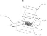
- the bird's-eye view which shows immediately before cut
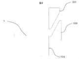
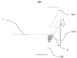
- the side view at the time of FIG. The bird's-eye view which shows immediately after cut
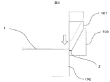
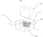
- the side view at the time of FIG. The bird's-eye view which shows the state laminated
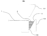
- the side view at the time of FIG. The bird's-eye view which shows the state which completed lamination
- This example is an example in the production of an iron core of an axial gap motor, and the mechanism of an apparatus for laminating iron core materials cut into strips will be described.
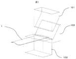
- FIG. 1 shows a state immediately before the material is cut into strips.
- a cutting upper blade 101 and a cutting lower blade 102 for cutting the iron core material 1 are provided.
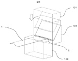
- FIG. 3 shows the state immediately after the first cutting, but after the material is sent out to a predetermined length and conveyed in this way, the core material 1 is cut into a strip shape by lowering the cutting upper blade 101. .
- the iron core material cut into a strip shape falls by its own weight, but a receiving die 103 is provided as a mechanism for receiving it.
- this receiving mold has a size and length corresponding to the thickness of the strip each time a strip material is laminated and stacked. It has a function to descend only.
- the lowering portion lowers the receiving mold in accordance with the stacking height of the iron cores stacked on the receiving mold.
- FIG. 5 shows a state in which approximately half of the required stacking amount is stacked, but the receiving mold is selected according to the stacking amount, the size corresponding to the stacked plate thickness, and the length. Lowering. Alternatively, the receiving mold is lowered in accordance with the stacking height of the iron core material stacked on the receiving mold.
- the receiving mold has a groove shape corresponding to the length of the material to be sequentially cut. Or it is set as the shape of the receiving type corresponding to the lamination
- the iron stack shape and the receiving groove are the same shape, and FIG. 7 shows a state in which the predetermined lamination is completed, but the space formed by the cut lower mold and the receiving groove is It matches the stacking shape of the iron core.
- a lowering mechanism for lowering the receiving mold there is a method of connecting a screw to the receiving mold and rotating the screw by the power of a motor or the like. An example of this is shown in FIG.
- the receiving mold 103 since the receiving mold 103 is provided with a female screw, it is supported by a screw block 105, and the receiving mold 103 can be lowered along the linear guide by the rotation of the external screw 104.
- the male screw 104 is rotated by the rotational drive of the driving unit 106, and the receiving mold 103 can be lowered and raised.
- the mechanism of the descending portion is an example, and any means can be used as long as it is a mechanism that can control the amount of movement corresponding to the plate thickness.
- FIG. 10 is a block diagram illustrating an iron core manufacturing apparatus that manufactures the iron core of the axial gap motor described above.
- the iron core material 1 is stored in a storage unit 150, for example, wound around a hoop, and the iron core material 1 is drawn out from the storage unit 150 by the conveyance unit 151 and conveyed.
- the conveyed iron core material 1 is cut by the cutting unit 152.
- the cut iron core material 1 is laminated by the laminated portion / lowering portion 153.
- the receiving mold on which the cut iron core material 1 is stacked is lowered by the lowering portion of the stacking portion / lowering portion 153.
- the iron core manufacturing apparatus 1500 can be operated by an input to the operation unit 154 or the like.
- the stored iron core material 1 is pulled out, sent, and conveyed (step 201).
- the conveyed iron core material 1 is cut and stacked (steps). 202)
- the receiving mold is lowered (step 203).
- step 204-NO if the predetermined number of iron core materials 1 stacked on the receiving mold are not reached (step 204-NO), the process returns to before step 201.
- step 204-YES if the core material 1 laminated on the receiving mold has a predetermined number (step 204-YES), the iron core manufacturing operation is terminated (step 205).
- the number of sheets of the core material 1 stacked in the receiving mold is a predetermined number or not.
- the present invention is not limited to this.
- a method for measuring the thickness or a method for measuring the laminated weight an alternative method may be used.
- the iron core material when the length of the iron core material is long, that is, when the feed amount up to a predetermined dimension to be cut is long, if the iron core material is a soft material, as illustrated in FIG. The leading edge of the material may hang down due to its own weight, which may occur.
- FIG. 13A the shape of the bottom surface 9 of the receiving mold is processed with an inclination angle a on the front end side in the material feeding direction.
- This inclination angle a is an angle in which the tip of the laminated strip material is expected to fall under its own weight, and a gap b is provided so that the iron core material being fed does not touch the laminated iron core material. .
- the amorphous material has a specific gravity equivalent to that of iron, but since the subject material is a foil strip having a plate thickness of about 0.025 mm, one strip material itself is very light. To make this an iron core, it is necessary to repeat several hundreds of layers. When the stacking is repeated, a slight gap is generated between the strips, so that it becomes higher than a predetermined stacking height. In other words, since the laminated shape of the iron core does not match the receiving groove shape, the strip materials may not be orderly laminated. In FIG. 14, the top end of the cutting upper blade presses the upper surface of the stacked strip material.
- the pressing depth of the cutting upper blade may be slightly deeper than the predetermined depth in consideration of the fact that the strip material floats back. Further, the pressing operation frequency may be intermittently performed instead of every time of cutting.
- An axial gap motor is a motor having a structure (also referred to as a face-to-face structure) in which a disc-shaped magnet and an exciting coil are axially opposed to each other with a gap in the axial direction.
- FIG. 15 there is a stationary iron core 510, a winding 520 is wound around the stationary iron core 510, and a magnet is disposed in a disk shape so as to face the stationary iron core 510 in the axial direction.
- the rotor 530 is supported by the rotation shaft 540.
- the rotating shaft 540 is rotatably supported by a bearing portion 550, and the bearing portion 550 and the stationary iron core 510 are supported by a housing 560.
- Iron core material 2 Cut iron core strip material 3: Strip material in the middle of lamination 4: Strip material in which lamination has been completed 5: Groove 6: Sag 7: Poor feed 8: Deviation of already laminated material 9: Bottom surface of groove 10: Inclination angle 11: Clearance 12: Contact portion 13: Pressing portion 101: Cutting upper blade 102: Cutting lower blade 103: Receiving die 104: Male screw 105: Female screw block 106: Screw rotation motor 107: Linear motion guide 150: Iron core Material holding part 151: Iron core material feeding part 152: Iron core material cutting part 153: Iron core material stacking part 154: Control part 200: Flow start 201: Flow processing box 1 202: Flow processing box 2 203: Flow processing box 3 204: Flow determination box 205: Flow end 510: Static iron core 520: Winding 530: Rotor 540: Rotating shaft 550: Bearing portion 560: Housing
Landscapes
- Engineering & Computer Science (AREA)
- Power Engineering (AREA)
- Manufacturing & Machinery (AREA)
- Manufacture Of Motors, Generators (AREA)
- Iron Core Of Rotating Electric Machines (AREA)
- Permanent Magnet Type Synchronous Machine (AREA)
- Manufacturing Cores, Coils, And Magnets (AREA)
Abstract
アキシャルギャップモータを製造するにあたり、その鉄心を製造する為に、鉄心材を短冊状に順次切断積層させて、積層量に応じて切断長を可変することで扇状に積層させる方法がある。この方法における鉄心の製造において、従来よりも鉄心の製造効率などを改善させることを課題とする。 短冊状に切断した鉄心材を積層する時、鉄心積み形状と同形状の受け型を、積層した積み高さに応じて、リニアに下降させながら積層するようにして、鉄心を製造し、この鉄心を用いて、アキシャルギャップモータを製造するようにする。
Description
本発明は、アキシャルギャップモータを製造する技術に関する。
近年、経済面や環境面を考慮して、更なる省エネルギーが世界的に謳われており、本対象製品である電気モータ分野においても高効率、低コスト化が要求されている。
アモルファス金属は低損失、高透磁率といった優れた特性があるため、モータ用の鉄心材料とした場合、モータの高効率化、低コスト化に貢献できる。
しかしその反面、アモルファス材は高硬度で脆性があるため、塑性加工が難しいことから、低コスト化を図るためには、製造方法に工夫が必要である。
本技術分野の背景技術として、特開2009-284578(特許文献1)がある。ここでは、アモルファス鉄心の製造方法として、一旦丸巻したアモルファスリボンを樹脂にて固着させ、それを扇状に分断する方法が記載されている。
この他に特開2010-115069(特許文献2)がある。ここでは、特許文献1と同様に、アモルファスリボンを丸巻し、その後樹脂等で固着させ分断する方法と、前記分断後の扇状に小さく巻回する方法の記載がある。
アキシャルギャップモータを製造するにあたり、そのモータ用のステータの鉄心において、アモルファス材または電磁鋼板を総称して鉄心材と言うが、これらの鉄心材を使用した鉄心の製造方法として、大きく下記の三通りが考えられる。なお、先行技術文献に記載があるものも、下記の三通りに含まれる。
一つ目は、鉄心材を丸巻し、それを樹脂等で固着させ、最後に扇状に分断する方法。二つ目は、鉄心材を扇状に巻回する方法。三つ目は鉄心材を短冊状に順次切断積層させて、積層量に応じて切断長を可変することで扇状に積層させる方法である。この三方式の中で最良と思われる方式は三つ目の方式であると考えられる。
なぜならば一つ目の方式は、扇状の個別鉄心に切断する際、刃物幅分の切断屑が発生することから、鉄心材の歩留まり低下につながる。
二つ目の方式は、高硬度で脆性のある鉄心材を小さく巻回し扇状を形成することは実現が困難であることに加え、積層型鉄心に比べて鉄損が大きくなること傾向にある。
三つ目の方式は、鉄心材を廃棄することなく使用でき、短冊を切断する長さを可変させることで、如何様な扇状の形状に積層することが可能となるためである。このことから、三つ目の方式による鉄心を作る手段を提供して、アキシャルギャップモータを製造することが課題である。
なお、三つ目の方式では、鉄心材を短冊の形状として、切断する長さを可変させることで、任意の扇状の形状に積層することを、いわゆる短冊切断積層方式と呼ぶものとする。
前記課題を解決するため、本発明のアキシャルギャップモータの製造での鉄心の製造方法について、本発明は、短冊状に切断した鉄心材の積層において、鉄心積み形状に対応した形状の受け型を、積層した積み高さに対応して下降させ、積層することを特徴とするものである。
さらに本発明は、次回切断分を送り出す時、既に積層済みの上部鉄心材との干渉を避けるため、受け型の積層形状を斜めにしていることを特徴とするものである。
さらに本発明は、切断上刃が下死点に達した後に、積層する材料を上から押さえることにより、積層鉄心の積み姿勢の安定化を図ることを特徴とするものである。
また、本発明の構成を以下に別の表現にて説明する。
本発明のアキシャルギャップモータの鉄心製造装置は、鉄心材が格納される格納部と、前記格納部から鉄心材が搬送される搬送部と、前記搬送部から搬送された鉄心材が切断される切断部と、前記切断部で切断された鉄心材が積層される積層部とを備え、前記積層部は、前記切断された鉄心材が積層される積層形状に対応する受け型と、前記受け型を下降させる下降部とを有し、前記切断部にて切断された鉄心材が前記積層部で積層される際に、前記受け型に積層された鉄心材の積み高さに対応して、前記受け型を前記下降部が下降させるようにする。
また、本発明のアキシャルギャップモータの鉄心製造方法は、格納された鉄心材が搬送され、次に、搬送された鉄心材が切断され、次に、切断された鉄心材が積層され、前記積層される鉄心材の積層形状に対応する受け型に前記切断された鉄心材が積層され、前記受け型に切断された鉄心材が積層される際に、前記受け型に積層された鉄心材の積み高さに対応して、前記受け型を下降させるようにする。
また、前記受け型を傾斜させ、前記切断部で切断された鉄心材が傾斜して積層されるようにする。
また、前記受け型に積層される鉄心材を押さえる押さえ部を設け、前記切断部で鉄心材が切断された後に、前記受け型に積層される鉄心材が前記押さえ部によって押さえられるようにする。
また、本発明のアキシャルギャップモータは、前記アキシャルギャップモータの鉄心製造装置において製造された鉄心を用いる静止鉄心と、前記静止鉄心に巻かれる巻線と、円板状に磁石が配置される回転子と、前記回転子の回転軸と、前記回転軸を支持する軸受け部と、前記巻線を有する静止鉄心と、前記軸受け部とを支持する筐体とを有する構成とされる。
また、本発明のアキシャルギャップモータは、前記アキシャルギャップモータの鉄心製造方法において製造された鉄心を用いる静止鉄心と、前記静止鉄心に巻かれる巻線と、円板状に磁石が配置される回転子と、前記回転子の回転軸と、前記回転軸を支持する軸受け部と、前記巻線を有する静止鉄心と、前記軸受け部とを支持する筐体とを有する構成とされる。
本発明の鉄心の製造によって、従来よりも、鉄心の製造効率などが改善され、例えば、安価なアキシャルギャップモータを提供することが可能となる。
以下、本発明の実施例について図面を用いて説明する。
本実施例は、アキシャルギャップモータの鉄心の製造における一例であり、短冊状に切断した鉄心材の積層を行う装置の機構を説明する。
図1は、材料を短冊状に切断する直前の状態を示している。ここでは、鉄心材1を切断する切断上刃101と切断下刃102が備えられている。
図3は一回目を切断した直後を示しているが、このように所定の長さに材料を送り出し、搬送した後、切断上刃101が下降することで鉄心材1が短冊状に切断される。この短冊状に切断された鉄心材は自重で落下するが、これを受ける機構として受け型103なるものを備えている。このように切断と積層を繰り返していくと鉄心材の板厚分だけ積層高さが増加するため、この受け型は短冊材を積層、重ねる度に、板厚分に対応する大きさ、長さだけ下降する機能を有している。若しくは、受け型に積層された鉄心材の積み高さに対応して、前記受け型を前記下降部が下降させる。
図5は必要積層量に対して、およそ半分まで積層した状態を示したものであるが、このように積層量、積層された板厚分に対応する大きさ、長さに応じて受け型を下降させている。若しくは、受け型に積層された鉄心材の積み高さに対応して、前記受け型を下降させている。
また、受け型は順次切断される材料の長さに応じた溝部形状としている。若しくは、切断された鉄心材が積層される積層形状に対応する受け型の形状としている。
例えば、鉄心積み形状と受け型の溝部を同形状とするものであり、図7は所定の積層が完了した状態を示すものであるが、切断下型と受け型の溝部によって形成される空間は、鉄心の積み形状に合致させている。
また、受け型を下降させる下降部の機構の一例として、受け型にねじを連結してモータなどの動力によりねじを回転させる方法がある。この一例を示したものが図9である。
図9では、受け型103がめねじの設けられためねじブロック105で支持されており、おねじ104の回転によって、受け型103は直動ガイドに沿って下降するように出来る。
おねじ104は、駆動部106の回転駆動によって、回転し、受け型103を下降・上昇させることが出来る。
なお、前記下降部の機構は、一例であり、これ例外にも板厚分の移動量を制御できる機構であれば特に手段を選ばない。
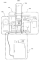
図10は、前述したアキシャルギャップモータの鉄心を製造する鉄心製造装置を説明するブロック図である。
図10において、鉄心材1は、格納部150に、例えばフープに巻かれて格納されており、前記格納部150から、鉄心材1が搬送部151によって、引き出され、搬送される。
次に、搬送された鉄心材1が切断部152によって、切断される。切断された鉄心材1は、積層部・下降部153によって、積層される。
この際に、切断された鉄心材1が積層される受け型が、積層部・下降部153の下降部によって、下降するようになっている。
なお、この鉄心製造装置1500は、操作部154への入力などによって、操作される様に出来る。
また、図11において、前記鉄心製造装置1500における鉄心の製造の手順を説明する。
鉄心の製造開始(ステップ200)によって、格納された鉄心材1が、引き出され、送られ、搬送される(ステップ201)、次に、搬送された鉄心材1が切断され、積層される(ステップ202)、その後、受け型が下降する(ステップ203)。
次に、受け型に積層された鉄心材1が所定の枚数となっていなければ(ステップ204-NO)、前記ステップ201の前迄戻る。
一方、受け型に積層された鉄心材1が所定の枚数となっていれば(ステップ204-YES)、鉄心製造の作業を終了する(ステップ205)。
前記ステップ204では、受け型に積層された鉄心材1が所定の枚数となっているか、否かの枚数のカウントとしているが、これに限定されるものではなく、例えば、積層された積み高さを測定する方法や、積層された重量を測定する方法として、代替するものであっても良い。
本実施例では、受け型の溝形状についての別の実施例を示したものである。
図12に示す通り、鉄心材の短冊長さ、つまり切断する所定寸法までの送り量が長い場合、鉄心材が軟弱材であると、図12(a)に例示するように、送りの途中で材料の先端が自重で垂れ下り6が発生してしまうことがある。
この時、既に積層してある鉄心材の上面に接触するため、材料同士の接触抵抗により、図12(b)に例示する送り不良7や、既に積層された鉄心材の位置をずらせる、図12(c)に例示する積層ずれ8などの不具合の発生が予想される。
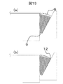
これに対して、図13(a)では、受け型の溝底面9の形状が材料送り方向の先端側に傾斜角度aを付けて加工されているものである。
この傾斜角度aは、積層した短冊材の先端が自重で落下することを見込んだ角度としており、送り途中の鉄心材が積層済みの鉄心材に触れないように、隙間bを設けるようにしている。
但し、図13(b)に例示するように、仮に触れた場合でも接触する面積12が小さいため、送り不良7や積層ずれ8を防止することができる。
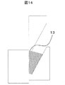
本実施例では、受け型に短冊材を整然と整列積層するための例を示したものである。鉄心材の中でも特にアモルファス材は、鉄と同等程度の比重があるが、本対象材料は板厚が0.025mm前後の箔帯のため、一つの短冊材自体は非常に軽量である。これを鉄心にするためには数百枚もの積層を繰り返す必要がある。積層を繰り返していくと短冊材同士の間にわずかではあるが空隙が生じるため、所定の積み高さより高くなってしまう。つまり、受け型溝形状に対して、鉄心の積層形状が合致しないため、短冊材が整然と積層されなくなる可能性がある。図14は、切断上刃の先端が積層済みの短冊材の上面を押付けているものである。このように切断上刃で積層済みの短冊材上面を押付けることによって、正規の鉄心積み形状に近づけることができるため、積層部でのトラブルを回避させ整然と積層させること可能となる。切断上刃の押付け深さは、短冊材が浮き戻ることを考慮して、所定深さより若干深めにしても良い。また押付け動作頻度は切断ごと毎回ではなくても、断続的に実施しても良い。
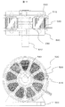
次に、図15において、本発明の実施例におけるアキシャルギャップモータを説明する。
アキシャルギャップモータは、円板形状の磁石と励磁コイルをアキシャル(軸方向)にギャップを持たせて、軸方向に対向させた構造(面対向構造とも呼ばれる)とするモータである。
図15に例示するように、静止鉄心510があり、前記静止鉄心510の回りには巻線520が巻かれ、前記静止鉄心510に軸方向に対向して、円板状に磁石が配置された回転子530が回転軸540によって、支持される。
前記回転軸540は、軸受け部550によって、回転自在に支持され、前記軸受け部550と、前記静止鉄心510が筐体560によって、支持される。
1:鉄心材
2:切断した鉄心短冊材
3:積層途中の短冊材
4:積層が完了した短冊材
5:溝部
6:垂れ下り
7:送り不良
8:既積層材のずれ
9:溝底面
10:傾斜角度
11:隙間
12:接触部分
13:押付け部分
101:切断上刃
102:切断下刃
103:受け型
104:おねじ
105:めねじブロック
106:ねじ回転用モータ
107:直動ガイド
150:鉄心材料保持部
151:鉄心材料送り部
152:鉄心材料切断部
153:鉄心材料積層部
154:制御部
200:フロー開始
201:フロー処理ボックス1
202:フロー処理ボックス2
203:フロー処理ボックス3
204:フロー判定ボックス
205:フロー終了
510:静止鉄心
520:巻線
530:回転子
540:回転軸
550:軸受け部
560:筐体。
2:切断した鉄心短冊材
3:積層途中の短冊材
4:積層が完了した短冊材
5:溝部
6:垂れ下り
7:送り不良
8:既積層材のずれ
9:溝底面
10:傾斜角度
11:隙間
12:接触部分
13:押付け部分
101:切断上刃
102:切断下刃
103:受け型
104:おねじ
105:めねじブロック
106:ねじ回転用モータ
107:直動ガイド
150:鉄心材料保持部
151:鉄心材料送り部
152:鉄心材料切断部
153:鉄心材料積層部
154:制御部
200:フロー開始
201:フロー処理ボックス1
202:フロー処理ボックス2
203:フロー処理ボックス3
204:フロー判定ボックス
205:フロー終了
510:静止鉄心
520:巻線
530:回転子
540:回転軸
550:軸受け部
560:筐体。
Claims (6)
- 鉄心材が格納される格納部と、
前記格納部から鉄心材が搬送される搬送部と、
前記搬送部から搬送された鉄心材が切断される切断部と、
前記切断部で切断された鉄心材が積層される積層部と
を備え、
前記積層部は、
前記切断された鉄心材が積層される積層形状に対応する受け型と、
前記受け型を下降させる下降部と
を有し、
前記切断部にて切断された鉄心材が前記積層部で積層される際に、
前記受け型に積層された鉄心材の積み高さに対応して、前記受け型を前記下降部が下降させる
ことを特徴とするアキシャルギャップモータの鉄心製造装置。 - 請求項1記載のアキシャルギャップモータの鉄心製造装置において、
前記受け型を傾斜させ、前記切断部で切断された鉄心材が傾斜して積層される
ことを特徴とするアキシャルギャップモータの鉄心製造装置。 - 請求項1記載のアキシャルギャップモータの鉄心製造装置において、
前記受け型に積層される鉄心材を押さえる押さえ部を設け、
前記切断部で鉄心材が切断された後に、
前記受け型に積層される鉄心材が前記押さえ部によって押さえられる
ことを特徴とするアキシャルギャップモータの鉄心製造装置。 - 格納された鉄心材が搬送され、
次に、搬送された鉄心材が切断され、
次に、切断された鉄心材が積層されて
アキシャルギャップモータの鉄心を製造するアキシャルギャップモータの鉄心の製造方法において、
前記積層される鉄心材の積層形状に対応する受け型に前記切断された鉄心材が積層され、
前記受け型に切断された鉄心材が積層される際に、
前記受け型に積層された鉄心材の積み高さに対応して、前記受け型を下降させる
ことを特徴とするアキシャルギャップモータの鉄心の製造方法。 - 請求項1記載のアキシャルギャップモータの鉄心製造装置において製造された鉄心を用いる静止鉄心と、
前記静止鉄心に巻かれる巻線と、
円板状に磁石が配置される回転子と、
前記回転子の回転軸と、
前記回転軸を支持する軸受け部と、
前記巻線を有する静止鉄心と、前記軸受け部とを支持する筐体と
を有することを特徴とするアキシャルギャップモータ。 - 請求項4記載のアキシャルギャップモータの鉄心製造方法において製造された鉄心を用いる静止鉄心と、
前記静止鉄心に巻かれる巻線と、
円板状に磁石が配置される回転子と、
前記回転子の回転軸と、
前記回転軸を支持する軸受け部と、
前記巻線を有する静止鉄心と、前記軸受け部とを支持する筐体と
を有することを特徴とするアキシャルギャップモータ。
Applications Claiming Priority (2)
| Application Number | Priority Date | Filing Date | Title |
|---|---|---|---|
| JP2012-209091 | 2012-09-24 | ||
| JP2012209091A JP5948198B2 (ja) | 2012-09-24 | 2012-09-24 | アキシャルギャップモータの鉄心の製造装置、アキシャルギャップモータの鉄心の製造方法、及びその鉄心を用いたアキシャルギャップモータ。 |
Publications (1)
| Publication Number | Publication Date |
|---|---|
| WO2014045694A1 true WO2014045694A1 (ja) | 2014-03-27 |
Family
ID=50341020
Family Applications (1)
| Application Number | Title | Priority Date | Filing Date |
|---|---|---|---|
| PCT/JP2013/069579 Ceased WO2014045694A1 (ja) | 2012-09-24 | 2013-07-19 | アキシャルギャップモータの鉄心の製造装置、アキシャルギャップモータの鉄心の製造方法、及びその鉄心を用いたアキシャルギャップモータ。 |
Country Status (2)
| Country | Link |
|---|---|
| JP (1) | JP5948198B2 (ja) |
| WO (1) | WO2014045694A1 (ja) |
Citations (3)
| Publication number | Priority date | Publication date | Assignee | Title |
|---|---|---|---|---|
| JP2009291059A (ja) * | 2008-06-02 | 2009-12-10 | Kuroda Precision Ind Ltd | 積層鉄心の製造装置及び製造方法 |
| JP2011066978A (ja) * | 2009-09-16 | 2011-03-31 | Daikin Industries Ltd | アキシャルギャップ型回転電機用ステータコア及びその製造方法 |
| JP2012095368A (ja) * | 2010-10-22 | 2012-05-17 | Honda Motor Co Ltd | 鉄心製造装置 |
-
2012
- 2012-09-24 JP JP2012209091A patent/JP5948198B2/ja not_active Expired - Fee Related
-
2013
- 2013-07-19 WO PCT/JP2013/069579 patent/WO2014045694A1/ja not_active Ceased
Patent Citations (3)
| Publication number | Priority date | Publication date | Assignee | Title |
|---|---|---|---|---|
| JP2009291059A (ja) * | 2008-06-02 | 2009-12-10 | Kuroda Precision Ind Ltd | 積層鉄心の製造装置及び製造方法 |
| JP2011066978A (ja) * | 2009-09-16 | 2011-03-31 | Daikin Industries Ltd | アキシャルギャップ型回転電機用ステータコア及びその製造方法 |
| JP2012095368A (ja) * | 2010-10-22 | 2012-05-17 | Honda Motor Co Ltd | 鉄心製造装置 |
Also Published As
| Publication number | Publication date |
|---|---|
| JP2014064421A (ja) | 2014-04-10 |
| JP5948198B2 (ja) | 2016-07-06 |
Similar Documents
| Publication | Publication Date | Title |
|---|---|---|
| CN103975504B (zh) | 旋转电机和旋转电机的制造方法 | |
| CN111052543B (zh) | 径向间隙型旋转电机及其制造方法、旋转电机用齿片的制造装置、旋转电机用齿构件的制造方法 | |
| CN106663980B (zh) | 轴向气隙型旋转电机及旋转电机用绕线架 | |
| CN111052545B (zh) | 径向间隙型旋转电机、其制造装置及其制造方法 | |
| CN105122609B (zh) | 向转子铁芯磁体插入孔的磁体插入装置以及方法 | |
| CN104396127A (zh) | 构成场磁极用磁体的磁体片的制造装置及其制造方法 | |
| JPWO2014102950A1 (ja) | 回転電機 | |
| JPWO2017149685A1 (ja) | アキシャルギャップ型回転電機及び回転電機固定子用ボビン | |
| JP2016032848A (ja) | シート材の切断装置 | |
| JP5948198B2 (ja) | アキシャルギャップモータの鉄心の製造装置、アキシャルギャップモータの鉄心の製造方法、及びその鉄心を用いたアキシャルギャップモータ。 | |
| JP6069475B2 (ja) | 回転電機 | |
| CN104795908B (zh) | 马达、马达的制造装置及马达的制造方法 | |
| KR20150097832A (ko) | 그린시트 절단 장치 및 방법 | |
| JP6987672B2 (ja) | セパレータシート切断装置 | |
| JP4182158B2 (ja) | セラミックグリーンシートの積層装置および積層方法 | |
| JP5418186B2 (ja) | 積層コア製造装置および積層コア製造方法 | |
| JP2015181344A (ja) | 非円形のステータコアを備えたモータ、モータの製造装置、およびモータの製造方法 | |
| CN204088505U (zh) | 叠片电芯制备装置 | |
| JP5557691B2 (ja) | 鉄心製造方法及び鉄心製造装置 | |
| JP5994447B2 (ja) | 界磁極用磁石体を構成する磁石片の製造装置及びその製造方法 | |
| CN1725599B (zh) | 内置型永磁无刷马达的转子结构 | |
| JP2012044761A (ja) | アキシャルギャップ型モータ、及びそのアキシャルギャップ型モータに用いられるティースの製造方法 | |
| CN203509396U (zh) | 一种太阳能电池片焊接机及其上料盒 | |
| CN104067489B (zh) | 构成场磁极用磁体的磁体片的制造方法 | |
| JPWO2022230376A5 (ja) |
Legal Events
| Date | Code | Title | Description |
|---|---|---|---|
| 121 | Ep: the epo has been informed by wipo that ep was designated in this application |
Ref document number: 13839975 Country of ref document: EP Kind code of ref document: A1 |
|
| NENP | Non-entry into the national phase |
Ref country code: DE |
|
| 122 | Ep: pct application non-entry in european phase |
Ref document number: 13839975 Country of ref document: EP Kind code of ref document: A1 |