WO2014045498A1 - 情報処理装置、情報処理装置の制御方法、圧分布計測システム、プログラムおよび記憶媒体 - Google Patents
情報処理装置、情報処理装置の制御方法、圧分布計測システム、プログラムおよび記憶媒体 Download PDFInfo
- Publication number
- WO2014045498A1 WO2014045498A1 PCT/JP2013/003842 JP2013003842W WO2014045498A1 WO 2014045498 A1 WO2014045498 A1 WO 2014045498A1 JP 2013003842 W JP2013003842 W JP 2013003842W WO 2014045498 A1 WO2014045498 A1 WO 2014045498A1
- Authority
- WO
- WIPO (PCT)
- Prior art keywords
- pressure distribution
- pressure
- information processing
- threshold
- warning
- Prior art date
- Legal status (The legal status is an assumption and is not a legal conclusion. Google has not performed a legal analysis and makes no representation as to the accuracy of the status listed.)
- Ceased
Links
Images



Classifications
-
- A—HUMAN NECESSITIES
- A61—MEDICAL OR VETERINARY SCIENCE; HYGIENE
- A61B—DIAGNOSIS; SURGERY; IDENTIFICATION
- A61B5/00—Measuring for diagnostic purposes; Identification of persons
- A61B5/68—Arrangements of detecting, measuring or recording means, e.g. sensors, in relation to patient
- A61B5/6887—Arrangements of detecting, measuring or recording means, e.g. sensors, in relation to patient mounted on external non-worn devices, e.g. non-medical devices
- A61B5/6892—Mats
-
- A—HUMAN NECESSITIES
- A61—MEDICAL OR VETERINARY SCIENCE; HYGIENE
- A61B—DIAGNOSIS; SURGERY; IDENTIFICATION
- A61B5/00—Measuring for diagnostic purposes; Identification of persons
- A61B5/103—Measuring devices for testing the shape, pattern, colour, size or movement of the body or parts thereof, for diagnostic purposes
- A61B5/1036—Measuring load distribution, e.g. podologic studies
Definitions
- the present invention relates to an information processing apparatus, a control method for the information processing apparatus, a pressure distribution measurement system, a program, and a storage medium.
- Pressure ulcers become important when the motor function declines and the time spent at the bedside increases. Pressure ulcers are symptoms in which, when a patient is bedridden with the same posture for a long period of time, pressure is applied to the contact area between the body and the support surface (mostly a bed), resulting in blood circulation failure and necrosis of surrounding tissues. . Generally, it is necessary to take measures when the pressure is 30 mmHg or more. Usually, countermeasures are taken by changing the softness of the bed or inserting a cushion (see, for example, Patent Document 1).
- the probe has a diameter of about several centimeters, if the probe is not inserted at an appropriate position, it is impossible to detect an excessive pressure. That is, there is a risk that the possibility of the subject's pressure ulcer may be missed.
- an object of the present invention is to provide an information processing apparatus that reduces the possibility of pressure ulcers of a subject.
- An information processing apparatus connectable to a pressure distribution meter including a pressure distribution detection sensor in which a plurality of pressure sensors are two-dimensionally arranged, Pressure distribution acquisition means for acquiring the pressure distribution detected by the pressure distribution detection sensor from the pressure distribution meter; Threshold determination means for determining whether at least a part of the pressure distribution acquired by the pressure distribution acquisition means exceeds a threshold; Warning means for giving a warning when it is determined by the threshold determination means that at least a part of the pressure distribution exceeds the threshold; It is characterized by providing.
- the possibility of the subject's pressure sore can be reduced.
- FIG. 2nd Embodiment of this invention It is a figure which shows an example of the warning which the warning part 204 which concerns on 1st Embodiment of this invention displays on the display part 210.
- It is a flowchart which shows the procedure of the process which the information processing apparatus 200 which concerns on 2nd Embodiment of this invention implements.
- FIG. 1 is a diagram illustrating an example of an external configuration of a pressure distribution measurement system 10 according to the present embodiment.
- the pressure distribution measurement system 10 includes a pressure distribution meter 100 and an information processing device 200, which are connected by a cable 300.
- a subject 400 is placed on the pressure distribution meter 100.
- the pressure distribution meter 100 includes a pressure distribution detection sensor 101 in which a plurality of pressure sensors are arranged in a two-dimensional manner, and can measure the pressure at a site in contact with the subject 400.
- the information processing apparatus 200 acquires the pressure distribution data measured by the pressure distribution meter 100 via the cable 300.
- the acquired pressure distribution data is displayed on the display unit. Accordingly, for example, when the pressure distribution meter 100 measures the body pressure distribution of the subject 400, the body pressure distribution of the subject can be displayed, so that the doctor or the physical therapist can check the state of the subject 400. Can be monitored.
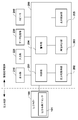
- FIG. 2 is a diagram illustrating a functional configuration of the pressure distribution meter 100 and the information processing apparatus 200 included in the pressure distribution measurement system 10.
- the pressure distribution meter 100 includes a pressure distribution detection sensor 101.
- the information processing apparatus 200 includes a control unit 201, a pressure distribution acquisition unit 202 (pressure distribution acquisition unit), a threshold determination unit 203 (threshold determination unit), a warning unit 204 (warning unit), and a display control unit 205 (display). Control means).
- the information processing apparatus 200 is connected to a display unit 210, an input unit 220 (input means), a data storage device 230, and a speaker 240.
- the control unit 201 controls the operation of each component by reading and executing a program stored in a storage medium such as the data storage device 230 or an internal memory (not shown).
- the pressure distribution acquisition unit 202 acquires the pressure distribution detected by the pressure distribution detection sensor 101 from the pressure distribution meter 100.
- the display unit 210 is, for example, a liquid crystal display, displays pressure distribution data acquired by the pressure distribution acquisition unit 202, or displays text information indicating that at least a part of the pressure distribution exceeds a threshold value.
- the input unit 220 includes, for example, a keyboard, a mouse, a touch panel, or the like, and accepts various inputs from the user.
- the threshold determination unit 203 receives a threshold setting used for determination from the user via the input unit 220.
- the input unit 220 receives an input of a pressure threshold value.
- a configuration that does not particularly accept input may be used, and in that case, a default value (for example, 30 mmHg) may be set as a threshold value. Further, it may be configured such that the user can determine and select whether or not the threshold value needs to be input.
- the pressure distribution acquisition unit 202 acquires the pressure distribution detected by the pressure distribution detection sensor 101 from the pressure distribution meter 100.
- the warning unit 204 displays text information indicating that at least part of the pressure distribution exceeds the threshold value on the display unit 210 and / or at least part of the pressure distribution through the speaker 240.
- a warning is given by notifying the voice information that the threshold is exceeded.
- a warning display 401 such as “Warning! Pressure limit value exceeds ⁇ ⁇ mmHg” shown in FIG.
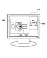
- a warning display 401 may be displayed on the display unit 210 together with the pressure distribution 501 of the subject 400 acquired by the pressure distribution acquisition unit 202.
- a warning may be issued by changing and displaying a region where the pressure exceeds the threshold as a high-pressure region 503 in a color different from the surroundings.
- a region where the pressure distribution is detected is formed roughly as a subject region 502 when the subject lies on the pressure distribution meter 100. When a subject lies down, as shown in FIG.
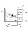
- a large pressure tends to be applied near the waist region. If pressure is continuously applied to a specific part of the subject, the possibility of pressure ulcer increases, so that a pressure alert can be used to prevent pressure ulcers when pressure exceeds a threshold. Further, as shown in FIG. 6, when the maximum value of the pressure distribution acquired by the pressure distribution acquisition unit 202 exceeds the threshold value, the maximum value may be displayed as a pressure display 601.
- the control unit 201 determines whether to continue the process. For example, when the subject 400 descends from the pressure distribution meter 100 and a predetermined time has passed since the pressure distribution is not measured, or when an instruction to end training (for example, the pressure distribution meter 100 or the information processing device 200) When the user turns off the power), the process is terminated when the threshold value is re-input. If it is determined to continue the process (S305; YES), the process returns to S302. On the other hand, when it is determined not to continue the process (S305; NO), the process of the flowchart of FIG. 3 ends.
- the warning unit 204 can continue the warning while the pressure exceeds the threshold value, and stops the warning when the pressure falls below the threshold value. Therefore, the state of the subject 400 can be monitored while referring to the warning by the warning unit 204, and it becomes easy to prevent pressure ulcers.
- a warning is given when the pressure applied to the subject exceeds the threshold. Thereby, the possibility of the subject's pressure ulcer can be reduced.
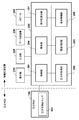
- FIG. 7 is a diagram illustrating a functional configuration of the pressure distribution meter 100 and the information processing apparatus 200 included in the pressure distribution measurement system 10.
- the pressure distribution meter 100 includes a pressure distribution detection sensor 101.
- the information processing apparatus 200 includes a control unit 201, a pressure distribution acquisition unit 202 (pressure distribution acquisition unit), a threshold determination unit 203 (threshold determination unit), a warning unit 204 (warning unit), and a display control unit 205 (display). Control means) and a relative pressure calculation unit 701 (relative pressure calculation means).
- the information processing apparatus 200 is connected to a display unit 210, an input unit 220 (input means), a data storage device 230, and a speaker 240.
- the relative pressure calculation unit 701 calculates a difference value between the maximum value of the pressure distribution acquired by the pressure distribution acquisition unit 202 and the average value of the pressure distribution. Or you may calculate the difference value of the highest value of the said pressure distribution, and the average value of the pressure distribution below a fixed value among the said pressure distribution.
- the threshold value determination unit 203 determines whether or not the difference value calculated by the relative pressure calculation unit 701 exceeds the threshold value.
- the threshold value to be compared does not necessarily match the threshold value described in the first embodiment, and is usually a different value.
- step S901 the input unit 220 receives an input of a pressure threshold value.
- a configuration that does not particularly accept input may be used, and in that case, a default value may be set as a threshold value. Further, it may be configured such that the user can determine and select whether or not the threshold value needs to be input.
- step S ⁇ b> 902 the pressure distribution acquisition unit 202 acquires the pressure distribution detected by the pressure distribution detection sensor 101 from the pressure distribution meter 100.
- the threshold value determination unit 203 determines whether the difference value between the maximum value and the average value of the pressure distribution calculated by the relative pressure calculation unit 701 exceeds the threshold value. When it is determined that the difference value exceeds the threshold (S905; YES), the process proceeds to S905. On the other hand, when it is determined that the difference value is equal to or smaller than the threshold value (S905; NO), the process proceeds to S907.
- step S ⁇ b> 906 the warning unit 204 displays text information indicating that too much pressure is applied on the display unit 210 based on the difference value exceeding the threshold value and / or through the speaker 240.
- a warning is given by notifying that the pressure is excessive by voice information. Details of the warning example by the warning unit 204 are the same as those in the first embodiment, and a description thereof will be omitted.
- the pressure distribution meter has been described as an example. However, not only body pressure distribution but also seat pressure distribution and foot pressure distribution are measured. Can be confirmed.
Landscapes
- Health & Medical Sciences (AREA)
- Life Sciences & Earth Sciences (AREA)
- Medical Informatics (AREA)
- Biophysics (AREA)
- Pathology (AREA)
- Engineering & Computer Science (AREA)
- Biomedical Technology (AREA)
- Heart & Thoracic Surgery (AREA)
- Physics & Mathematics (AREA)
- Molecular Biology (AREA)
- Surgery (AREA)
- Animal Behavior & Ethology (AREA)
- General Health & Medical Sciences (AREA)
- Public Health (AREA)
- Veterinary Medicine (AREA)
- Dentistry (AREA)
- Oral & Maxillofacial Surgery (AREA)
- Measuring And Recording Apparatus For Diagnosis (AREA)
- Force Measurement Appropriate To Specific Purposes (AREA)
Description
本発明は、情報処理装置、情報処理装置の制御方法、圧分布計測システム、プログラムおよび記憶媒体に関する。
高齢化に伴い脳卒中などの脳神経系疾患を発症する患者や、関節症など運動器に関連する疾患が増加している。発症すると運動機能が低下するため、場合によっては寝たきりになる可能性がある。
運動機能が低下してベッドサイドにいる時間が長くなると褥瘡対策が重要になる。褥瘡とは、患者が長期にわたり同じ体勢で寝たきり等になった場合、体と支持面(多くはベッド)との接触局所に圧がかかり、血行不全となって周辺組織に壊死を起こす症状をいう。一般に、圧が30mmHg以上になると対策を採る必要がある。通常はベッドの柔らかさを変えたり、クッションを入れたりすることにより対策が採られている(例えば、特許文献1参照)。
この圧のかかり過ぎを判定するものとして、プローブを圧がかかりそうな場所に挿入し、その場所の圧力を計測する方法が考えられる。
しかしながら、プローブは直径数cm程度であるため、適切な位置にプローブが挿入されていない場合には、圧のかかり過ぎを発見することができない。すなわち、被検者の褥瘡の可能性を見逃してしまうおそれがある。
上記の課題に鑑み、本発明は、被検者の褥瘡の可能性を低減する情報処理装置を提供することを目的とする。
上記の目的を達成する本発明に係る情報処理装置は、
複数の圧力センサが2次元に配列された圧分布検出センサを含む圧分布計と接続可能な情報処理装置であって、
前記圧分布計から前記圧分布検出センサにより検出された圧分布を取得する圧分布取得手段と、
前記圧分布取得手段により取得された前記圧分布の少なくとも一部が閾値を超過しているか否かを判定する閾値判定手段と、
前記閾値判定手段により前記圧分布の少なくとも一部が閾値を超過していると判定された場合に、警告を行う警告手段と、
を備えることを特徴とする。
複数の圧力センサが2次元に配列された圧分布検出センサを含む圧分布計と接続可能な情報処理装置であって、
前記圧分布計から前記圧分布検出センサにより検出された圧分布を取得する圧分布取得手段と、
前記圧分布取得手段により取得された前記圧分布の少なくとも一部が閾値を超過しているか否かを判定する閾値判定手段と、
前記閾値判定手段により前記圧分布の少なくとも一部が閾値を超過していると判定された場合に、警告を行う警告手段と、
を備えることを特徴とする。
また、上記の目的を達成する本発明に係る別の情報処理装置は、
複数の圧力センサが2次元に配列された圧分布検出センサを含む圧分布計と接続可能な情報処理装置であって、
前記圧分布計から前記圧分布検出センサにより検出された圧分布を取得する圧分布取得手段と、
前記圧分布取得手段により取得された前記圧分布の最高値と、当該圧分布の平均値との差分値を算出する相対圧算出手段と、
前記差分値が閾値を超過しているか否かを判定する閾値判定手段と、
前記閾値判定手段により前記差分値が閾値を超過していると判定された場合に、警告を行う警告手段と、
を備えることを特徴とする。
複数の圧力センサが2次元に配列された圧分布検出センサを含む圧分布計と接続可能な情報処理装置であって、
前記圧分布計から前記圧分布検出センサにより検出された圧分布を取得する圧分布取得手段と、
前記圧分布取得手段により取得された前記圧分布の最高値と、当該圧分布の平均値との差分値を算出する相対圧算出手段と、
前記差分値が閾値を超過しているか否かを判定する閾値判定手段と、
前記閾値判定手段により前記差分値が閾値を超過していると判定された場合に、警告を行う警告手段と、
を備えることを特徴とする。
本発明によれば、被検者の褥瘡の可能性を低減することができる。
本発明のその他の特徴及び利点は、添付図面を参照とした以下の説明により明らかになるであろう。なお、添付図面においては、同じ若しくは同様の構成には、同じ参照番号を付す。
添付図面は明細書に含まれ、その一部を構成し、本発明の実施の形態を示し、その記述と共に本発明の原理を説明するために用いられる。
本発明の第1実施形態に係る圧分布計測システム10の外観構成の一例を示す図である。
本発明の第1実施形態に係る圧分布計測システム10が備える圧分布計100および情報処理装置200の機能構成を示す図である。
本発明の第1実施形態に係る情報処理装置200が実施する処理の手順を示すフローチャートである。
本発明の第1実施形態に係る警告部204が表示部210上に表示する警告の一例を示す図である。
本発明の第1実施形態に係る警告部204が表示部210上に表示する警告の一例を示す図である。
本発明の第1実施形態に係る警告部204が表示部210上に表示する警告の一例を示す図である。
本発明の第2実施形態に係る圧分布計測システム10が備える圧分布計100および情報処理装置200の機能構成を示す図である。
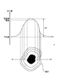
本発明の第2実施形態に係る相対圧算出部701が実施する処理の説明図である。
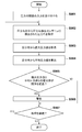
本発明の第2実施形態に係る情報処理装置200が実施する処理の手順を示すフローチャートである。
以下、本発明の各実施形態について図面を参照しながら説明する。なお、以下に述べる実施形態は、本発明の好適な具体例であるから、種々の限定がされているが、特に本発明を限定する旨の記載がない限り、これらの態様に限られるものではない。
[第1実施形態]
<1.圧分布計測システムの外観構成>
図1は、本実施形態に係る圧分布計測システム10の外観構成の一例を示す図である。圧分布計測システム10は、圧分布計100と、情報処理装置200とを備えており、これらはケーブル300によって接続されている。そして圧分布計100の上に被検者400が載っている。
<1.圧分布計測システムの外観構成>
図1は、本実施形態に係る圧分布計測システム10の外観構成の一例を示す図である。圧分布計測システム10は、圧分布計100と、情報処理装置200とを備えており、これらはケーブル300によって接続されている。そして圧分布計100の上に被検者400が載っている。
圧分布計100は、複数の圧力センサが2次元に配列された圧分布検出センサ101を備えており、被検者400と接触した部位の圧力を測定することができる。情報処理装置200は、圧分布計100において計測された圧分布データをケーブル300を介して取得する。また、取得した圧分布データを表示部に表示する。これにより、例えば圧分布計100が被検者400の体圧分布を計測する場合、被検者の体圧分布を表示することができるので、医師や理学療法士は被検者400の状態を監視することができる。
<2.圧分布計測システムが備える圧分布計および情報処理装置の機能構成>
図2は、圧分布計測システム10が備える圧分布計100および情報処理装置200の機能構成を示す図である。圧分布計100は、圧分布検出センサ101を備えている。情報処理装置200は、制御部201と、圧分布取得部202(圧分布取得手段)と、閾値判定部203(閾値判定手段)と、警告部204(警告手段)と、表示制御部205(表示制御手段)とを備えている。また情報処理装置200は、表示部210と、入力部220(入力手段)と、データ記憶装置230と、スピーカ240と接続されている。
図2は、圧分布計測システム10が備える圧分布計100および情報処理装置200の機能構成を示す図である。圧分布計100は、圧分布検出センサ101を備えている。情報処理装置200は、制御部201と、圧分布取得部202(圧分布取得手段)と、閾値判定部203(閾値判定手段)と、警告部204(警告手段)と、表示制御部205(表示制御手段)とを備えている。また情報処理装置200は、表示部210と、入力部220(入力手段)と、データ記憶装置230と、スピーカ240と接続されている。
制御部201は、データ記憶装置230または不図示の内部メモリ等の記憶媒体に記憶されたプログラムを読み出して実行することにより、各構成要素の動作を制御する。圧分布取得部202は、圧分布計100から圧分布検出センサ101により検出された圧分布を取得する。
閾値判定部203は、圧分布取得部202により取得された圧分布の少なくとも一部が閾値を超過しているか否かを判定する。警告部204は、閾値判定部203により圧分布の少なくとも一部が閾値を超過していると判定された場合に、警告を行う。表示制御部205は、圧分布取得部202により取得された圧分布を表示部210に表示する。
表示部210は、例えば液晶ディスプレイであり、圧分布取得部202により取得された圧分布データを表示したり、圧分布の少なくとも一部が閾値を超過していることを示すテキスト情報を表示したりする。入力部220は、例えばキーボード、マウス、またはタッチパネル等で構成されており、ユーザからの各種入力を受け付ける。例えば、閾値判定部203が判定に用いる閾値の設定を入力部220を介してユーザから受け付ける。
データ記憶装置230は、制御部201が実行するプログラムを格納し、圧分布計100から取得した圧分布データや、入力部220を介してユーザから受け付けた閾値等を記憶する。スピーカ240は、閾値判定部203により圧分布の少なくとも一部が閾値を超過していると判定された場合、その旨を音声情報で報知する。なお、表示部210乃至スピーカ240は情報処理装置200と一体形成あるいは内蔵されていてもよい。
<3.情報処理装置が実施する処理の手順>
以下、図3のフローチャートを参照して、第1実施形態に係る情報処理装置200が実施する処理の手順を説明する。
以下、図3のフローチャートを参照して、第1実施形態に係る情報処理装置200が実施する処理の手順を説明する。
S301において、入力部220は、圧の閾値の入力を受け付ける。なお、特に入力を受け付けない構成であってもよく、その場合デフォルトの値(例えば30mmHg)を閾値として設定すればよい。また、閾値の入力の要否をユーザが判断して選択できるように構成してもよい。S302において、圧分布取得部202は、圧分布計100から圧分布検出センサ101により検出された圧分布を取得する。
S303において、閾値判定部203は、圧分布取得部202により取得された圧分布の少なくとも一部が閾値を超過しているか否かを判定する。圧分布の少なくとも一部が閾値を超過していると判定された場合(S303;YES)、S304へ進む。一方、圧分布の少なくとも一部が閾値以下であると判定された場合(S303;NO)、S305へ進む。
S304において、警告部204は、圧分布の少なくとも一部が閾値を超過していることを示すテキスト情報を表示部210に表示することにより、および/または、スピーカ240を通じて圧分布の少なくとも一部が閾値を超過していることを音声情報で報知することにより、警告を行う。
警告部204による警告例について図4乃至図6を参照して説明する。例えば、図4に示す「警告!圧力制限値●●mmHgを超えています」というような警告表示401を表示部210上に表示する。また図5に示すように、圧分布取得部202により取得された被検者400の圧分布501と併せて警告表示401を表示部210上に表示してもよい。また、圧力が閾値を超過している領域を、高圧領域503として周囲と異なる色に変更して表示することにより警告を行ってもよい。なお、図5において、被検者が圧分布計100上に横たわることで、圧分布が検出される領域が概略的に被検者領域502のように形成されている。被検者が横たわる場合には、図5に示すように一般に腰領域の付近に大きな圧力がかかる傾向がある。被検者の特定の部位に継続的に圧が加わると、褥瘡の可能性が高くなるため、圧が閾値を超過する場合に警告を行うことで褥瘡を防止することができる。さらには図6に示すように、圧分布取得部202により取得された圧分布の最高値が閾値を超過する場合には、当該最高値を圧力表示601のように表示してもよい。
S305において、制御部201は、処理を継続するか否かを判定する。例えば、被検者400が圧分布計100上から降りて、圧分布が計測されなくなって所定時間が経過した場合や、ユーザから訓練終了の指示(例えば、圧分布計100や情報処理装置200の電源をユーザがOFFにした。)を受けた場合、閾値が再入力された場合等に処理を終了する。処理を継続すると判定された場合(S305;YES)、S302に戻る。一方、処理を継続しないと判定された場合(S305;NO)、図3のフローチャートの処理が終了する。
図3のフローチャートの処理を継続的に行うことで、警告部204は圧が閾値を超過している間警告を継続することができ、閾値以下になったら警告を停止することになる。したがって、警告部204による警告を参考にしながら被検者400の状態を監視することができ、褥瘡を防止することが容易になる。
以上説明したように、本実施形態では、被検者に加わる圧が閾値を超過する場合に警告を行う。これにより、被検者の褥瘡の可能性を低減することができる。
[第2実施形態]
第1実施形態では、圧分布計上に被検者が載り、圧が閾値を超過する場合に警告を行う例を説明した。その際、圧の絶対値と閾値との比較を行った。
第1実施形態では、圧分布計上に被検者が載り、圧が閾値を超過する場合に警告を行う例を説明した。その際、圧の絶対値と閾値との比較を行った。
これに対して、第2実施形態では、被検者の個人差を吸収するために、相対的な評価を行う例を説明する。なお、以下の説明では、第1実施形態で説明した構成要素と同一の構成要素には同一の参照符号を付し、詳細な説明は省略する。なお、圧分布計測システムの外観構成は第1実施形態と同様である。
<1.圧分布計測システムが備える圧分布計および情報処理装置の機能構成>
図7は、圧分布計測システム10が備える圧分布計100および情報処理装置200の機能構成を示す図である。圧分布計100は、圧分布検出センサ101を備えている。情報処理装置200は、制御部201と、圧分布取得部202(圧分布取得手段)と、閾値判定部203(閾値判定手段)と、警告部204(警告手段)と、表示制御部205(表示制御手段)と、相対圧算出部701(相対圧算出手段)とを備えている。また情報処理装置200は、表示部210と、入力部220(入力手段)と、データ記憶装置230と、スピーカ240と接続されている。
図7は、圧分布計測システム10が備える圧分布計100および情報処理装置200の機能構成を示す図である。圧分布計100は、圧分布検出センサ101を備えている。情報処理装置200は、制御部201と、圧分布取得部202(圧分布取得手段)と、閾値判定部203(閾値判定手段)と、警告部204(警告手段)と、表示制御部205(表示制御手段)と、相対圧算出部701(相対圧算出手段)とを備えている。また情報処理装置200は、表示部210と、入力部220(入力手段)と、データ記憶装置230と、スピーカ240と接続されている。
制御部201は、データ記憶装置230または不図示の内部メモリ等の記憶媒体に記憶されたプログラムを読み出して実行することにより、各構成要素の動作を制御する。圧分布取得部202は、圧分布計100から圧分布検出センサ101により検出された圧分布を取得する。
相対圧算出部701は、圧分布取得部202により取得された圧分布の最高値と、当該圧分布の平均値との差分値を算出する。あるいは、当該圧分布の最高値と、当該圧分布のうち一定値以下の圧分布の平均値との差分値を算出してもよい。
閾値判定部203は、相対圧算出部701により算出された差分値が閾値を超過しているか否かを判定する。ここで比較対象とされる閾値は第1実施形態で説明した閾値とは必ずしも一致せず、通常は異なる値である。
警告部204は、相対圧算出部701により算出された差分値が閾値判定部203により閾値を超過していると判定された場合に、警告を行う。警告の方法は第1実施形態と同様である。表示制御部205は、圧分布取得部202により取得された圧分布を表示部210に表示する。
<2.情報処理装置が実施する処理の手順>
以下、図8および図9のフローチャートを参照して、第1実施形態に係る情報処理装置200が実施する処理の手順を説明する。
以下、図8および図9のフローチャートを参照して、第1実施形態に係る情報処理装置200が実施する処理の手順を説明する。
S901において、入力部220は、圧の閾値の入力を受け付ける。なお、特に入力を受け付けない構成であってもよく、その場合デフォルトの値を閾値として設定すればよい。また、閾値の入力の要否をユーザが判断して選択できるように構成してもよい。S902において、圧分布取得部202は、圧分布計100から圧分布検出センサ101により検出された圧分布を取得する。
S903において、相対圧算出部701は、圧分布取得部202により取得された圧分布の最高値を取得する。S904において、相対圧算出部701は、圧分布取得部202により取得された圧分布の平均値を算出する。平均値は圧力が検出されたすべての圧分センサの測定値の合計を、圧力が検出された圧分センサの数で割ったものになる。
ここで、図8を参照して、圧分布の最高値の取得および平均値の算出処理について説明する。図8は、被検者400の圧分布501のA-A’断面について圧力分布の値をグラフ化した図である。圧力の最高値については、圧分布取得部202により取得された圧分布データから取得することができる。一方、圧力平均値は、全体領域についての圧力平均値を算出することにより求める。また、圧力値がある一定値を超過する領域の圧力値を除いた領域における圧力の平均値を算出することによって求めてもよい。すなわち、圧分布の最高値と、当該圧分布のうち一定値以下の圧分布の平均値との差分値を算出してもよい。これにより、比較的低圧領域についての平均値を算出することができるため、圧力値が高い領域の影響を排除することができる。そのため、圧力の最高値と最低値との差分値により近い値を求めることができるようになり、被検者の特定の部位に極端に大きな圧力がかかっていることを認識できるようになる。
S905において、閾値判定部203は、相対圧算出部701により算出された圧分布の最高値と平均値との差分値が閾値を超過しているか否かを判定する。差分値が閾値を超過していると判定された場合(S905;YES)、S905へ進む。一方、差分値が閾値以下であると判定された場合(S905;NO)、S907へ進む。
S906において、警告部204は、差分値が閾値を超過していることに基づいて、圧がかかり過ぎであることを示すテキスト情報を表示部210に表示することにより、および/または、スピーカ240を通じて圧がかかり過ぎであることを音声情報で報知することにより、警告を行う。警告部204による警告例の詳細については第1実施形態と同様であるため説明を省略する。
S907において、制御部201は、処理を継続するか否かを判定する。例えば、被検者400が圧分布計100上から降りて、圧分布が計測されなくなって所定時間が経過した場合や、ユーザから訓練終了の指示(例えば、圧分布計100や情報処理装置200の電源をユーザがOFFにした。)を受けた場合、閾値が再入力された場合等に処理を終了する。処理を継続すると判定された場合(S907;YES)、S902に戻る。一方、処理を継続しないと判定された場合(S907;NO)、図9のフローチャートの処理が終了する。
図9のフローチャートの処理を継続的に行うことで、警告部204は圧が閾値を超過している間警告を継続することができ、閾値以下になったら警告を停止することになる。したがって、警告部204による警告を参考にしながら被検者400の状態を監視することができ、褥瘡を防止することが容易になる。
以上説明したように、本実施形態では、圧分布取得部により取得された被検者の圧分布の最高値と、当該圧分布の平均値との差分値を算出し、当該差分値が閾値を超過している場合に警告を行う。これにより、被検者の体重や体格、骨格等の個人差を吸収した相対的な評価を行うことが可能となり、より精度良く褥瘡の可能性を認識することができる。
また、以上の説明では圧分布計を例にして説明を行ったが、体圧分布に限らず、座圧分布、足圧分布を計測する場合には本発明を適用して、褥瘡の有無を確認することができる。
本発明は上記実施の形態に制限されるものではなく、本発明の精神及び範囲から離脱することなく、様々な変更及び変形が可能である。従って、本発明の範囲を公にするために、以下の請求項を添付する。
本願は、2012年9月24日提出の日本国特許出願特願2012-210103を基礎として優先権を主張するものであり、その記載内容の全てを、ここに援用する。
Claims (15)
- 複数の圧力センサが2次元に配列された圧分布検出センサを含む圧分布計と接続可能な情報処理装置であって、
前記圧分布計から前記圧分布検出センサにより検出された圧分布を取得する圧分布取得手段と、
前記圧分布取得手段により取得された前記圧分布の少なくとも一部が閾値を超過しているか否かを判定する閾値判定手段と、
前記閾値判定手段により前記圧分布の少なくとも一部が閾値を超過していると判定された場合に、警告を行う警告手段と、
を備えることを特徴とする情報処理装置。 - 前記警告手段は、前記圧分布の少なくとも一部が閾値を超過していることを示すテキスト情報を表示部に表示することにより警告を行うことを特徴とする請求項1に記載の情報処理装置。
- 前記圧分布取得手段により取得された前記圧分布を表示部に表示する表示制御手段をさらに備えることを特徴とする請求項1または2に記載の情報処理装置。
- 前記警告手段は、前記表示部に表示されている前記圧分布のうち閾値を超過している領域を強調表示することにより警告を行うことを特徴とする請求項3に記載の情報処理装置。
- 前記警告手段は、前記圧分布の少なくとも一部が閾値を超過していることを示す音声情報を報知することにより警告を行うことを特徴とする請求項1に記載の情報処理装置。
- 前記警告手段は、前記圧分布の少なくとも一部が閾値を超過していることを示すテキスト情報を表示部に表示し、且つ、前記圧分布の少なくとも一部が閾値を超過していることを示す音声情報を報知することにより、警告を行うことを特徴とする請求項1に記載の情報処理装置。
- 前記警告手段は、前記圧分布取得手段により取得された前記圧分布が閾値を超過している場合に、前記圧分布の最高値を表示部に表示することにより、前記警告を行うことを特徴とする請求項1に記載の情報処理装置。
- 複数の圧力センサが2次元に配列された圧分布検出センサを含む圧分布計と接続可能な情報処理装置であって、
前記圧分布計から前記圧分布検出センサにより検出された圧分布を取得する圧分布取得手段と、
前記圧分布取得手段により取得された前記圧分布の最高値と、当該圧分布の平均値との差分値を算出する相対圧算出手段と、
前記差分値が閾値を超過しているか否かを判定する閾値判定手段と、
前記閾値判定手段により前記差分値が閾値を超過していると判定された場合に、警告を行う警告手段と、
を備えることを特徴とする情報処理装置。 - 前記相対圧算出手段は、前記圧分布取得手段により取得された前記圧分布の最高値と、当該圧分布のうち一定値以下の圧分布の平均値との差分値を算出することを特徴とする請求項8に記載の情報処理装置。
- 複数の圧力センサが2次元に配列された圧分布検出センサを含む圧分布計と接続可能な情報処理装置の制御方法であって、
前記圧分布計から前記圧分布検出センサにより検出された圧分布を取得する圧分布取得工程と、
前記圧分布取得工程により取得された前記圧分布の少なくとも一部が閾値を超過しているか否かを判定する閾値判定工程と、
前記閾値判定工程により前記圧分布の少なくとも一部が閾値を超過していると判定された場合に、警告を行う警告工程と、
を有することを特徴とする情報処理装置の制御方法。 - 複数の圧力センサが2次元に配列された圧分布検出センサを含む圧分布計と接続可能な情報処理装置の制御方法であって、
前記圧分布計から前記圧分布検出センサにより検出された圧分布を取得する圧分布取得工程と、
前記圧分布取得工程により取得された前記圧分布の最高値と、当該圧分布の平均値との差分値を算出する相対圧算出工程と、
前記差分値が閾値を超過しているか否かを判定する閾値判定工程と、
前記閾値判定工程により前記差分値が閾値を超過していると判定された場合に、警告を行う警告工程と、
を有することを特徴とする情報処理装置の制御方法。 - 請求項10または11に記載の情報処理装置の制御方法の各工程をコンピュータに実行させるためのプログラム。
- 請求項12に記載のプログラムが記憶されたコンピュータ読み取り可能な記憶媒体。
- 複数の圧力センサが2次元に配列された圧分布検出センサを含む圧分布計と、当該圧分布計と接続可能な情報処理装置とを備える圧分布計測システムであって、
前記情報処理装置は、
前記圧分布計から前記圧分布検出センサにより検出された圧分布を取得する圧分布取得手段と、
前記圧分布取得手段により取得された前記圧分布の少なくとも一部が閾値を超過しているか否かを判定する閾値判定手段と、
前記閾値判定手段により前記圧分布の少なくとも一部が閾値を超過していると判定された場合に、警告を行う警告手段と、
を備えることを特徴とする圧分布計測システム。 - 複数の圧力センサが2次元に配列された圧分布検出センサを含む圧分布計と、当該圧分布計と接続可能な情報処理装置とを備える圧分布計測システムであって、
前記情報処理装置は、
前記圧分布計から前記圧分布検出センサにより検出された圧分布を取得する圧分布取得手段と、
前記圧分布取得手段により取得された前記圧分布の最高値と、当該圧分布の平均値との差分値を算出する相対圧算出手段と、
前記差分値が閾値を超過しているか否かを判定する閾値判定手段と、
前記閾値判定手段により前記差分値が閾値を超過していると判定された場合に、警告を行う警告手段と、
を備えることを特徴とする圧分布計測システム。
Priority Applications (1)
| Application Number | Priority Date | Filing Date | Title |
|---|---|---|---|
| JP2014536560A JPWO2014045498A1 (ja) | 2012-09-24 | 2013-06-20 | 情報処理装置、情報処理装置の制御方法、圧分布計測システム、プログラムおよび記憶媒体 |
Applications Claiming Priority (2)
| Application Number | Priority Date | Filing Date | Title |
|---|---|---|---|
| JP2012210103 | 2012-09-24 | ||
| JP2012-210103 | 2012-09-24 |
Publications (1)
| Publication Number | Publication Date |
|---|---|
| WO2014045498A1 true WO2014045498A1 (ja) | 2014-03-27 |
Family
ID=50340841
Family Applications (1)
| Application Number | Title | Priority Date | Filing Date |
|---|---|---|---|
| PCT/JP2013/003842 Ceased WO2014045498A1 (ja) | 2012-09-24 | 2013-06-20 | 情報処理装置、情報処理装置の制御方法、圧分布計測システム、プログラムおよび記憶媒体 |
Country Status (2)
| Country | Link |
|---|---|
| JP (1) | JPWO2014045498A1 (ja) |
| WO (1) | WO2014045498A1 (ja) |
Cited By (1)
| Publication number | Priority date | Publication date | Assignee | Title |
|---|---|---|---|---|
| JP2023150961A (ja) * | 2022-03-31 | 2023-10-16 | マクセル株式会社 | 荷重検出装置 |
Citations (5)
| Publication number | Priority date | Publication date | Assignee | Title |
|---|---|---|---|---|
| JP2006094903A (ja) * | 2004-09-28 | 2006-04-13 | Pentax Corp | 圧力検出マット及び褥瘡防止システム |
| JP2009106545A (ja) * | 2007-10-30 | 2009-05-21 | Univ Of Occupational & Environmental Health Japan | 足底圧計測装置及び行動姿勢判別方法 |
| JP2009128074A (ja) * | 2007-11-20 | 2009-06-11 | Terumo Corp | 光干渉断層画像診断装置 |
| WO2010119441A2 (en) * | 2009-04-13 | 2010-10-21 | Wellsense Technologies | System and method for preventing decubitus ulcers |
| JP2011047711A (ja) * | 2009-08-25 | 2011-03-10 | Keepu:Kk | 接触圧測定方法 |
Family Cites Families (2)
| Publication number | Priority date | Publication date | Assignee | Title |
|---|---|---|---|---|
| JP2003269447A (ja) * | 2002-03-15 | 2003-09-25 | Nsk Ltd | センサ付軸受装置及びセンサ付軸受装置の異常検知方法 |
| JP2009076407A (ja) * | 2007-09-25 | 2009-04-09 | Panasonic Electric Works Co Ltd | 放電灯点灯装置、照明装置、バックライト装置 |
-
2013
- 2013-06-20 JP JP2014536560A patent/JPWO2014045498A1/ja active Pending
- 2013-06-20 WO PCT/JP2013/003842 patent/WO2014045498A1/ja not_active Ceased
Patent Citations (5)
| Publication number | Priority date | Publication date | Assignee | Title |
|---|---|---|---|---|
| JP2006094903A (ja) * | 2004-09-28 | 2006-04-13 | Pentax Corp | 圧力検出マット及び褥瘡防止システム |
| JP2009106545A (ja) * | 2007-10-30 | 2009-05-21 | Univ Of Occupational & Environmental Health Japan | 足底圧計測装置及び行動姿勢判別方法 |
| JP2009128074A (ja) * | 2007-11-20 | 2009-06-11 | Terumo Corp | 光干渉断層画像診断装置 |
| WO2010119441A2 (en) * | 2009-04-13 | 2010-10-21 | Wellsense Technologies | System and method for preventing decubitus ulcers |
| JP2011047711A (ja) * | 2009-08-25 | 2011-03-10 | Keepu:Kk | 接触圧測定方法 |
Cited By (1)
| Publication number | Priority date | Publication date | Assignee | Title |
|---|---|---|---|---|
| JP2023150961A (ja) * | 2022-03-31 | 2023-10-16 | マクセル株式会社 | 荷重検出装置 |
Also Published As
| Publication number | Publication date |
|---|---|
| JPWO2014045498A1 (ja) | 2016-08-18 |
Similar Documents
| Publication | Publication Date | Title |
|---|---|---|
| TWI495453B (zh) | 循環動態測定裝置 | |
| US11550005B2 (en) | Method and apparatus for providing content related to capture of medical image | |
| JP6077184B2 (ja) | 被検者の膀胱容量をモニタリングするための装置及び方法 | |
| EP3813653B1 (en) | Mobile device applications to measure blood pressure | |
| JP6149929B2 (ja) | 診断装置、診断方法及びプログラム | |
| JP2020127757A (ja) | 生体情報出力装置 | |
| JP2013517850A (ja) | 褥瘡性潰瘍形成に対する危険性のモデリング手法 | |
| JP2013541371A (ja) | 被験者の呼吸活動をモニタする方法と装置 | |
| JP7170646B2 (ja) | 術後出血を早期検出するためのシステム | |
| WO2012114588A9 (ja) | 睡眠評価装置および睡眠評価装置における表示方法 | |
| JP6779978B2 (ja) | 肺機能測定装置、肺機能測定方法および肺機能測定プログラム | |
| EP3641641A2 (en) | Non-contact heart rate monitoring | |
| JP2009225854A (ja) | 体組成情報測定装置 | |
| JP6547838B2 (ja) | 診断支援装置、診断支援方法、診断支援プログラム | |
| JP6202485B2 (ja) | 生体情報管理モジュール、睡眠計、およびシステム | |
| JP2013066570A (ja) | バイタル計測器 | |
| JPWO2014045498A1 (ja) | 情報処理装置、情報処理装置の制御方法、圧分布計測システム、プログラムおよび記憶媒体 | |
| CN109414201B (zh) | 生物信息测定装置和存储介质 | |
| KR20170066358A (ko) | 마사지기 및 신체 컨디션 관리 시스템 | |
| JP6151703B2 (ja) | 情報処理装置、情報処理装置の制御方法、圧分布計測システム、および記憶媒体 | |
| JP6428664B2 (ja) | 生体情報表示装置 | |
| JP6233776B2 (ja) | 心身状態判定装置及び心身状態判定プログラム | |
| KR101602704B1 (ko) | 척추 질환 판단 장치 및 방법 | |
| WO2018168804A1 (ja) | 血圧関連情報表示装置および方法 | |
| WO2023189443A1 (ja) | 生体音測定装置、生体音測定方法、及びプログラム |
Legal Events
| Date | Code | Title | Description |
|---|---|---|---|
| 121 | Ep: the epo has been informed by wipo that ep was designated in this application |
Ref document number: 13839528 Country of ref document: EP Kind code of ref document: A1 |
|
| ENP | Entry into the national phase |
Ref document number: 2014536560 Country of ref document: JP Kind code of ref document: A |
|
| NENP | Non-entry into the national phase |
Ref country code: DE |
|
| 122 | Ep: pct application non-entry in european phase |
Ref document number: 13839528 Country of ref document: EP Kind code of ref document: A1 |