WO2014045429A1 - Method for manufacturing windmill blade - Google Patents
Method for manufacturing windmill blade Download PDFInfo
- Publication number
- WO2014045429A1 WO2014045429A1 PCT/JP2012/074351 JP2012074351W WO2014045429A1 WO 2014045429 A1 WO2014045429 A1 WO 2014045429A1 JP 2012074351 W JP2012074351 W JP 2012074351W WO 2014045429 A1 WO2014045429 A1 WO 2014045429A1
- Authority
- WO
- WIPO (PCT)
- Prior art keywords
- fiber sheet
- resin
- wind turbine
- impregnated
- turbine blade
- Prior art date
Links
- 238000000034 method Methods 0.000 title claims abstract description 40
- 238000004519 manufacturing process Methods 0.000 title claims abstract description 39
- 239000000835 fiber Substances 0.000 claims abstract description 243
- 229920005989 resin Polymers 0.000 claims abstract description 166
- 239000011347 resin Substances 0.000 claims abstract description 166
- 229920001187 thermosetting polymer Polymers 0.000 claims abstract description 97
- 229920002430 Fibre-reinforced plastic Polymers 0.000 claims abstract description 16
- 239000011151 fibre-reinforced plastic Substances 0.000 claims abstract description 15
- 239000007788 liquid Substances 0.000 claims abstract description 11
- 239000012783 reinforcing fiber Substances 0.000 claims description 121
- 238000005470 impregnation Methods 0.000 claims description 52
- 238000011144 upstream manufacturing Methods 0.000 claims description 26
- 239000011162 core material Substances 0.000 claims description 17
- 230000002093 peripheral effect Effects 0.000 claims description 14
- 238000004804 winding Methods 0.000 claims description 5
- 229920000049 Carbon (fiber) Polymers 0.000 claims description 3
- 239000004917 carbon fiber Substances 0.000 claims description 3
- 239000004918 carbon fiber reinforced polymer Substances 0.000 claims description 2
- 238000013007 heat curing Methods 0.000 claims description 2
- 238000010030 laminating Methods 0.000 description 47
- 238000003475 lamination Methods 0.000 description 12
- 230000008569 process Effects 0.000 description 11
- 238000003825 pressing Methods 0.000 description 8
- 238000000465 moulding Methods 0.000 description 6
- 239000003795 chemical substances by application Substances 0.000 description 5
- 238000001723 curing Methods 0.000 description 5
- 230000008707 rearrangement Effects 0.000 description 5
- 230000007547 defect Effects 0.000 description 4
- 230000006872 improvement Effects 0.000 description 3
- 238000005304 joining Methods 0.000 description 3
- 230000007774 longterm Effects 0.000 description 3
- 230000007246 mechanism Effects 0.000 description 3
- 238000005057 refrigeration Methods 0.000 description 3
- 238000007652 sheet-forming process Methods 0.000 description 3
- 239000002904 solvent Substances 0.000 description 3
- 238000003860 storage Methods 0.000 description 3
- 230000003187 abdominal effect Effects 0.000 description 2
- 238000007664 blowing Methods 0.000 description 2
- 238000010586 diagram Methods 0.000 description 2
- 239000004744 fabric Substances 0.000 description 2
- 239000003365 glass fiber Substances 0.000 description 2
- 239000000463 material Substances 0.000 description 2
- 230000009467 reduction Effects 0.000 description 2
- 230000002787 reinforcement Effects 0.000 description 2
- 239000002759 woven fabric Substances 0.000 description 2
- 240000007182 Ochroma pyramidale Species 0.000 description 1
- 210000001015 abdomen Anatomy 0.000 description 1
- 239000000654 additive Substances 0.000 description 1
- 230000000996 additive effect Effects 0.000 description 1
- 229920006231 aramid fiber Polymers 0.000 description 1
- 238000009826 distribution Methods 0.000 description 1
- 230000000694 effects Effects 0.000 description 1
- 239000003822 epoxy resin Substances 0.000 description 1
- 239000011159 matrix material Substances 0.000 description 1
- VNWKTOKETHGBQD-UHFFFAOYSA-N methane Chemical compound C VNWKTOKETHGBQD-UHFFFAOYSA-N 0.000 description 1
- 239000005011 phenolic resin Substances 0.000 description 1
- 229920006122 polyamide resin Polymers 0.000 description 1
- 229920000647 polyepoxide Polymers 0.000 description 1
- 230000001737 promoting effect Effects 0.000 description 1
- 230000000452 restraining effect Effects 0.000 description 1
- 238000001721 transfer moulding Methods 0.000 description 1
- 230000009466 transformation Effects 0.000 description 1
- 229920006305 unsaturated polyester Polymers 0.000 description 1
Images


Classifications
-
- F—MECHANICAL ENGINEERING; LIGHTING; HEATING; WEAPONS; BLASTING
- F03—MACHINES OR ENGINES FOR LIQUIDS; WIND, SPRING, OR WEIGHT MOTORS; PRODUCING MECHANICAL POWER OR A REACTIVE PROPULSIVE THRUST, NOT OTHERWISE PROVIDED FOR
- F03D—WIND MOTORS
- F03D1/00—Wind motors with rotation axis substantially parallel to the air flow entering the rotor
- F03D1/06—Rotors
- F03D1/065—Rotors characterised by their construction elements
- F03D1/0675—Rotors characterised by their construction elements of the blades
-
- B—PERFORMING OPERATIONS; TRANSPORTING
- B29—WORKING OF PLASTICS; WORKING OF SUBSTANCES IN A PLASTIC STATE IN GENERAL
- B29C—SHAPING OR JOINING OF PLASTICS; SHAPING OF MATERIAL IN A PLASTIC STATE, NOT OTHERWISE PROVIDED FOR; AFTER-TREATMENT OF THE SHAPED PRODUCTS, e.g. REPAIRING
- B29C70/00—Shaping composites, i.e. plastics material comprising reinforcements, fillers or preformed parts, e.g. inserts
- B29C70/04—Shaping composites, i.e. plastics material comprising reinforcements, fillers or preformed parts, e.g. inserts comprising reinforcements only, e.g. self-reinforcing plastics
- B29C70/06—Fibrous reinforcements only
- B29C70/10—Fibrous reinforcements only characterised by the structure of fibrous reinforcements, e.g. hollow fibres
- B29C70/16—Fibrous reinforcements only characterised by the structure of fibrous reinforcements, e.g. hollow fibres using fibres of substantial or continuous length
- B29C70/20—Fibrous reinforcements only characterised by the structure of fibrous reinforcements, e.g. hollow fibres using fibres of substantial or continuous length oriented in a single direction, e.g. roofing or other parallel fibres
-
- B—PERFORMING OPERATIONS; TRANSPORTING
- B29—WORKING OF PLASTICS; WORKING OF SUBSTANCES IN A PLASTIC STATE IN GENERAL
- B29C—SHAPING OR JOINING OF PLASTICS; SHAPING OF MATERIAL IN A PLASTIC STATE, NOT OTHERWISE PROVIDED FOR; AFTER-TREATMENT OF THE SHAPED PRODUCTS, e.g. REPAIRING
- B29C70/00—Shaping composites, i.e. plastics material comprising reinforcements, fillers or preformed parts, e.g. inserts
- B29C70/04—Shaping composites, i.e. plastics material comprising reinforcements, fillers or preformed parts, e.g. inserts comprising reinforcements only, e.g. self-reinforcing plastics
- B29C70/28—Shaping operations therefor
- B29C70/30—Shaping by lay-up, i.e. applying fibres, tape or broadsheet on a mould, former or core; Shaping by spray-up, i.e. spraying of fibres on a mould, former or core
-
- B—PERFORMING OPERATIONS; TRANSPORTING
- B29—WORKING OF PLASTICS; WORKING OF SUBSTANCES IN A PLASTIC STATE IN GENERAL
- B29C—SHAPING OR JOINING OF PLASTICS; SHAPING OF MATERIAL IN A PLASTIC STATE, NOT OTHERWISE PROVIDED FOR; AFTER-TREATMENT OF THE SHAPED PRODUCTS, e.g. REPAIRING
- B29C70/00—Shaping composites, i.e. plastics material comprising reinforcements, fillers or preformed parts, e.g. inserts
- B29C70/04—Shaping composites, i.e. plastics material comprising reinforcements, fillers or preformed parts, e.g. inserts comprising reinforcements only, e.g. self-reinforcing plastics
- B29C70/28—Shaping operations therefor
- B29C70/40—Shaping or impregnating by compression not applied
- B29C70/50—Shaping or impregnating by compression not applied for producing articles of indefinite length, e.g. prepregs, sheet moulding compounds [SMC] or cross moulding compounds [XMC]
- B29C70/504—Shaping or impregnating by compression not applied for producing articles of indefinite length, e.g. prepregs, sheet moulding compounds [SMC] or cross moulding compounds [XMC] using rollers or pressure bands
-
- D—TEXTILES; PAPER
- D02—YARNS; MECHANICAL FINISHING OF YARNS OR ROPES; WARPING OR BEAMING
- D02J—FINISHING OR DRESSING OF FILAMENTS, YARNS, THREADS, CORDS, ROPES OR THE LIKE
- D02J1/00—Modifying the structure or properties resulting from a particular structure; Modifying, retaining, or restoring the physical form or cross-sectional shape, e.g. by use of dies or squeeze rollers
- D02J1/18—Separating or spreading
-
- B—PERFORMING OPERATIONS; TRANSPORTING
- B29—WORKING OF PLASTICS; WORKING OF SUBSTANCES IN A PLASTIC STATE IN GENERAL
- B29B—PREPARATION OR PRETREATMENT OF THE MATERIAL TO BE SHAPED; MAKING GRANULES OR PREFORMS; RECOVERY OF PLASTICS OR OTHER CONSTITUENTS OF WASTE MATERIAL CONTAINING PLASTICS
- B29B15/00—Pretreatment of the material to be shaped, not covered by groups B29B7/00 - B29B13/00
- B29B15/08—Pretreatment of the material to be shaped, not covered by groups B29B7/00 - B29B13/00 of reinforcements or fillers
- B29B15/10—Coating or impregnating independently of the moulding or shaping step
- B29B15/12—Coating or impregnating independently of the moulding or shaping step of reinforcements of indefinite length
- B29B15/122—Coating or impregnating independently of the moulding or shaping step of reinforcements of indefinite length with a matrix in liquid form, e.g. as melt, solution or latex
-
- B—PERFORMING OPERATIONS; TRANSPORTING
- B29—WORKING OF PLASTICS; WORKING OF SUBSTANCES IN A PLASTIC STATE IN GENERAL
- B29C—SHAPING OR JOINING OF PLASTICS; SHAPING OF MATERIAL IN A PLASTIC STATE, NOT OTHERWISE PROVIDED FOR; AFTER-TREATMENT OF THE SHAPED PRODUCTS, e.g. REPAIRING
- B29C70/00—Shaping composites, i.e. plastics material comprising reinforcements, fillers or preformed parts, e.g. inserts
- B29C70/04—Shaping composites, i.e. plastics material comprising reinforcements, fillers or preformed parts, e.g. inserts comprising reinforcements only, e.g. self-reinforcing plastics
- B29C70/06—Fibrous reinforcements only
- B29C70/10—Fibrous reinforcements only characterised by the structure of fibrous reinforcements, e.g. hollow fibres
- B29C70/16—Fibrous reinforcements only characterised by the structure of fibrous reinforcements, e.g. hollow fibres using fibres of substantial or continuous length
-
- Y—GENERAL TAGGING OF NEW TECHNOLOGICAL DEVELOPMENTS; GENERAL TAGGING OF CROSS-SECTIONAL TECHNOLOGIES SPANNING OVER SEVERAL SECTIONS OF THE IPC; TECHNICAL SUBJECTS COVERED BY FORMER USPC CROSS-REFERENCE ART COLLECTIONS [XRACs] AND DIGESTS
- Y02—TECHNOLOGIES OR APPLICATIONS FOR MITIGATION OR ADAPTATION AGAINST CLIMATE CHANGE
- Y02E—REDUCTION OF GREENHOUSE GAS [GHG] EMISSIONS, RELATED TO ENERGY GENERATION, TRANSMISSION OR DISTRIBUTION
- Y02E10/00—Energy generation through renewable energy sources
- Y02E10/70—Wind energy
- Y02E10/72—Wind turbines with rotation axis in wind direction
-
- Y—GENERAL TAGGING OF NEW TECHNOLOGICAL DEVELOPMENTS; GENERAL TAGGING OF CROSS-SECTIONAL TECHNOLOGIES SPANNING OVER SEVERAL SECTIONS OF THE IPC; TECHNICAL SUBJECTS COVERED BY FORMER USPC CROSS-REFERENCE ART COLLECTIONS [XRACs] AND DIGESTS
- Y02—TECHNOLOGIES OR APPLICATIONS FOR MITIGATION OR ADAPTATION AGAINST CLIMATE CHANGE
- Y02P—CLIMATE CHANGE MITIGATION TECHNOLOGIES IN THE PRODUCTION OR PROCESSING OF GOODS
- Y02P70/00—Climate change mitigation technologies in the production process for final industrial or consumer products
- Y02P70/50—Manufacturing or production processes characterised by the final manufactured product
Definitions
- fiber reinforced plastic has been used as a structural member for wind turbine blades.
- a typical method for manufacturing a wind turbine blade using fiber-reinforced plastic a method is known in which a fiber woven fabric sheet placed on a mold is impregnated with a resin, and the resin is heated and cured to form the wind turbine blade.
- a method for forming a wind turbine blade by placing a prepreg in which a resin impregnated in a fiber woven fabric sheet is semi-cured in advance up to the B stage on a mold, and heat-curing the resin of the prepreg. There is.
- Patent Document 1 describes a method of manufacturing a wind turbine blade by laminating a bundle of glass fiber rovings drawn from a bobbin and impregnated with a resin on a mold without using a fiber fabric (Patent Document 1). 1 FIG. 1).
- the method for manufacturing a wind turbine blade further includes a step of winding the reinforcing fiber sheet around a bobbin to form a roll of the reinforcing fiber sheet, and the step of forming the resin-impregnated fiber sheet includes: In a state where one end of the reinforcing fiber sheet of the roll is fixed by a clamp, the cart to which the roll having the reinforcing fiber sheet wound around the bobbin is attached is moved away from the clamp along the longitudinal direction of the mold.
- the wind turbine blade is molded using the resin-impregnated fiber sheet in which the fiber sheet is impregnated with the thermosetting resin
- the roving bundle is laminated on the mold.
- the time and labor required for the laminating work can be reduced.
- the thermosetting resin is liquid, the impregnation property to the reinforcing fiber sheet is good, and since it is solventless, the solvent volatilization step can be omitted.
- thermosetting resin in which the thermosetting resin is in an uncured state
- the fluidity of the thermosetting resin at the time of molding is good, and the quality is high.
- a windmill blade can be obtained.
- the resin-impregnated fiber sheet is wound around a bobbin to temporarily form a roll of the resin-impregnated fiber sheet, and in step S8, the resin-impregnated fiber sheet is pulled out from the roll.
- the resin impregnated fiber sheet is laminated on the mold.
- a plurality of nozzles 12 are arranged along the sheet width direction as shown in FIG.
- the plurality of nozzles 12 arranged in the sheet width direction reciprocate in the sheet width direction along with the movable portion 14, thereby promoting the opening of the fiber bundle 2.
- a plurality of nozzle rows including a plurality of nozzles 12 arranged in the sheet width direction may be provided in the sheet conveyance direction.
- the fiber bundles are formed on the rollers 8A and 8B in a state where almost no tension is applied to the reinforcing fiber sheet 3. Since it contacts, the opening of the fiber bundle 2 can be assisted more effectively.
- the fiber bundle 2 is opened only by the vibration of at least one of the rollers 8A and 8B of the downstream clamping unit 8 without providing the compressed gas discharge unit 10.
- a vibration roller for opening the fiber bundle 2 is separately provided between the upstream side clamping unit 6 and the downstream side clamping unit 8.
- a roll 30 around which a resin-impregnated fiber sheet 21 is wound is rotatably attached to a frame 202 by a bearing (not shown). Further, the end portion of the resin-impregnated fiber sheet 21 fed out from the roll 30 is fixed to the mold M itself, a gantry supporting the mold M, or the like by a clamp 206. Therefore, when the laminating apparatus 200 moves on the rail R so as to move away from the clamp 206, the resin-impregnated fiber sheet 21 having a length corresponding to the moving amount of the laminating apparatus 200 is pulled out from the roll 30 and laminated on the mold M. .
- the sheet position adjusting roller 210 and the sheet pressing roller 220 are attached to the frame 202.
- the sheet position adjusting roller 210 is configured to be lockable at an arbitrary angular position.
- the sheet position adjusting roller 210 is normally locked at an angular position (normal angular position) whose longitudinal direction is orthogonal to the cart traveling direction, and only when the position of the resin-impregnated fiber sheet 21 needs to be corrected.
- the lock is released.
- the sheet position adjustment roller 210 is rotated around the rotation shaft 212 according to the position correction amount of the resin-impregnated fiber sheet 21, and the sheet position adjustment roller 210 is locked at this angular position.
- the lock of the sheet position adjustment roller 210 is released, the sheet position adjustment roller 210 is returned to the normal angle position, and the angle position of the sheet position adjustment roller 210 is locked again.
- FIG. 8 the same parts as those of the roll forming apparatus 100 shown in FIG. 3 are denoted by the same reference numerals, and the description thereof is omitted as appropriate.
- FIGS. 9A and 9B the same parts as those of the stacking apparatus 200 shown in FIGS. 5A and 5B are denoted by the same reference numerals, and the description thereof is omitted as appropriate.
- the impregnation unit 420 impregnates the thermosetting resin 23 into the resin bath 422 storing the solvent-free and liquid thermosetting resin 23 and the reinforcing fiber sheet 3 drawn out from the roll 330. And impregnating roller 424.
- the impregnation roller 424 is provided such that the lower part is immersed in the thermosetting resin 23 in the resin bath 422 and the upper part is in contact with the reinforcing fiber sheet 3.
- a part of the thermosetting resin 23 in the resin bath 422 adheres to the outer peripheral surface of the impregnation roller 424 and contacts between the impregnation roller 424 and the reinforcing fiber sheet 3.
- This set value may be determined so that the reinforcing fiber sheet 3 is appropriately impregnated with the thermosetting resin 23 according to the viscosity of the thermosetting resin 23 and the affinity with the reinforcing fiber sheet 3. .
- the temperature setting value of the thermosetting resin 23 or the reinforcing fiber sheet 3 is determined so that the viscosity of the thermosetting resin 23 when impregnating the reinforcing fiber sheet 3 is 30 to 170 Pa ⁇ s.
- the roll 330 of the reinforcing fiber sheet 3 before impregnation with the thermosetting resin 23 can be stored for a long period of time even at room temperature, and does not require refrigeration for long-term storage of the roll 330, thereby reducing costs. Leads to.
- a release sheet that can be easily peeled later may be interposed between the layers of the reinforcing fiber sheet 3 of the roll 330.
- This release sheet is provided with a number of through holes through which the thermosetting resin 23 injected into the inner space 344 of the roll 330 can pass.
- the release sheet is mesh-like. In this way, by interposing the release sheet between the layers of the reinforcing fiber sheet 3 of the roll 330, between the layers of the resin-impregnated fiber sheet 21 obtained by injecting the thermosetting resin 23 into the inner space 344 of the roll 330. Adhesion can be prevented.
- the wind turbine blade is used by using the resin-impregnated fiber sheet 21 in which the reinforcing fiber sheet 3 obtained from the plurality of fiber bundles 2 drawn from the bobbin 1 is impregnated with the thermosetting resin 23. Therefore, the time and labor required for the laminating work can be reduced. Further, it is basically unnecessary to consider the twisting and undulations of the roving bundle that may lead to defects in the structural members of the wind turbine blade. Moreover, since the thermosetting resin 23 is liquid, the impregnation property to the reinforcing fiber sheet 3 is good, and since it is solventless, the solvent volatilization step can be omitted.
Abstract
Description
また、熱硬化性樹脂は、液状であるため強化繊維シートへの含浸性が良好であり、かつ、無溶剤であるため溶剤揮発工程を省略できる。さらに、熱硬化性樹脂が未硬化の状態である樹脂含浸繊維シートをモールド上に配置して風車翼の成形を行うから、成形時における熱硬化性樹脂の流動性が良好であり、高品質な風車翼を得ることができる。 According to the method for manufacturing a wind turbine blade, the wind turbine blade is molded using a resin-impregnated fiber sheet obtained by impregnating a reinforcing fiber sheet obtained from a plurality of fiber bundles drawn from a bobbin with a thermosetting resin. Therefore, the time and labor required for the laminating operation can be reduced as compared with the case where the roving bundle is laminated on the mold. Further, it is basically unnecessary to consider the twisting and undulations of the roving bundle that may lead to defects in the structural members of the wind turbine blade.
Moreover, since the thermosetting resin is liquid, the impregnation property to the reinforcing fiber sheet is good, and since it is solventless, the solvent volatilization step can be omitted. Furthermore, since the resin impregnated fiber sheet in which the thermosetting resin is in an uncured state is placed on the mold and the wind turbine blade is molded, the fluidity of the thermosetting resin at the time of molding is good, and the quality is high. A windmill blade can be obtained.
このように上流側挟持部と下流側挟持部とのローラの周速を互いに一致させれば、上流側挟持部と下流側挟持部との間において連続的に搬送される複数本の繊維束には殆んどテンションは加わらないため、繊維束の開繊を効果的に行うことができる。よって、厚さが均一な強化繊維シートが得られ、風車翼の品質向上につながる。 In some embodiments, in the step of obtaining the reinforcing fiber sheet, a plurality of fiber bundles that are continuously conveyed are clamped by an upstream clamping unit and a downstream clamping unit each including a pair of rollers. The fiber bundle is opened between the upstream clamping unit and the downstream clamping unit, and the peripheral speeds of the rollers of the upstream clamping unit and the downstream clamping unit are matched.
Thus, if the circumferential speeds of the rollers of the upstream side clamping unit and the downstream side clamping unit are made to coincide with each other, a plurality of fiber bundles continuously conveyed between the upstream side clamping unit and the downstream side clamping unit are obtained. Since almost no tension is applied, the fiber bundle can be effectively opened. Therefore, a reinforcing fiber sheet having a uniform thickness is obtained, which leads to an improvement in the quality of the wind turbine blade.
ノズルからの圧縮気体が吹きつけられると、各繊維束に属していた繊維が隣接する繊維束に向かって移動し、隣接する繊維束間の境界が曖昧になる。すなわち、圧縮気体によって、各繊維束がばらけて、隣接する繊維束との間で繊維の再配置が起きて、元々あった繊維束間の境界はもはや認識しがたくなる。こうして、繊維束の開繊が効果的に行われる。
この際、上流側挟持部と下流側挟持部とのローラの周速を互いに一致させれば、繊維束に殆んどテンションが加わらない状態で圧縮気体が繊維束に吹き付けられるため、繊維束の開繊をより一層効果的に行うことができる。 In some embodiments, in the step of obtaining the reinforcing fiber sheet, at least one disposed between the upstream-side sandwiching portion and the downstream-side sandwiching portion so as to face the plurality of aligned fiber bundles. While the two nozzles are reciprocated in the width direction of the reinforcing fiber sheet, the fiber bundle is opened by the compressed gas ejected from the nozzles.
When the compressed gas from the nozzle is blown, the fibers belonging to each fiber bundle move toward the adjacent fiber bundle, and the boundary between the adjacent fiber bundles becomes ambiguous. That is, the fiber bundles are separated by the compressed gas, and fiber rearrangement occurs between adjacent fiber bundles, so that the boundary between the original fiber bundles can no longer be recognized. Thus, the fiber bundle is effectively opened.
At this time, if the circumferential speeds of the rollers of the upstream clamping unit and the downstream clamping unit are made to coincide with each other, the compressed gas is blown onto the fiber bundle with almost no tension applied to the fiber bundle. Opening can be performed more effectively.
下流側挟持部の一対のローラの少なくとも一方が振動すると、繊維束がばらけて、隣接する繊維束との間で繊維の再配置が起きて、繊維束の開繊を効果的に行うことができる。この際、上流側挟持部と下流側挟持部とのローラの周速を互いに一致させれば、繊維束に殆んどテンションが加わらない状態で振動するローラに繊維束が接触するため、繊維束の開繊をより一層効果的に行うことができる。 In some embodiments, in the step of obtaining the reinforcing fiber sheet, the fiber bundle is opened by vibrating at least one of the rollers of the downstream clamping unit.
When at least one of the pair of rollers of the downstream clamping unit vibrates, the fiber bundle is separated, and the fiber is rearranged between adjacent fiber bundles, so that the fiber bundle can be effectively opened. it can. At this time, if the circumferential speeds of the rollers of the upstream side clamping part and the downstream side clamping part are made to coincide with each other, the fiber bundle comes into contact with the vibrating roller with almost no tension applied to the fiber bundle. Can be more effectively performed.
強化繊維シートの幅方向にローラが振動すると、隣接する繊維束間における繊維の再配置が促進され、繊維束の開繊を効果的に行うことができる。 In one embodiment, in the step of obtaining the reinforcing fiber sheet, the roller is vibrated in the width direction of the reinforcing fiber sheet.
When the roller vibrates in the width direction of the reinforcing fiber sheet, the rearrangement of the fibers between the adjacent fiber bundles is promoted, and the fiber bundles can be effectively opened.
これにより、樹脂含浸繊維シートにおける熱硬化性樹脂と強化繊維との含有比を適切に調節でき、風車翼の強度向上につながる。 In some embodiments, in the step of forming the resin-impregnated fiber sheet, after the uncured thermosetting resin is impregnated in the reinforcing fiber sheet, the resin-impregnated fiber sheet is sandwiched between a pair of rollers. The content of the uncured thermosetting resin in the resin-impregnated fiber sheet is adjusted.
Thereby, the content ratio of the thermosetting resin and the reinforcing fiber in the resin-impregnated fiber sheet can be appropriately adjusted, and the strength of the wind turbine blade is improved.
風車翼の製造プロセスにおいて、樹脂含浸繊維シートの形成工程と風車翼の成形工程とが連続していると、樹脂含浸繊維シートを形成してこれをモールド上に積層するまでを一つの作業単位として、これを繰り返し行うことになる。そのため、リードタイムを短縮することは困難である。
これに対し、上述のように、樹脂含浸繊維シートを一旦ボビンに巻き取って樹脂含浸繊維シートのロールを形成する場合、樹脂含浸繊維シートのロールの形成工程と、風車翼の成形工程とが分離される。そのため、風車翼の製造プロセスの生産性向上の観点から、各工程に投入するリソース(人員や設備)を適切に配分できる。よって、風車翼の効率的な製造が可能になる。 In some embodiments, the method of manufacturing a wind turbine blade further includes a step of winding the resin-impregnated fiber sheet around a bobbin to form at least one roll of the resin-impregnated fiber sheet, and forming the wind turbine blade In the step of performing, the resin-impregnated fiber sheet is pulled out from the roll, and the resin-impregnated fiber sheet is laminated on the mold.
In the manufacturing process of the wind turbine blade, if the resin impregnated fiber sheet forming process and the wind turbine blade forming process are continuous, the process until the resin impregnated fiber sheet is formed and laminated on the mold is taken as one unit of work. This will be repeated. Therefore, it is difficult to shorten the lead time.
On the other hand, as described above, when the resin-impregnated fiber sheet is wound around a bobbin to form a roll of the resin-impregnated fiber sheet, the process of forming the roll of the resin-impregnated fiber sheet and the process of forming the wind turbine blade are separated. Is done. Therefore, from the viewpoint of improving the productivity of the wind turbine blade manufacturing process, it is possible to appropriately allocate resources (personnel and equipment) to be input to each process. Therefore, efficient manufacture of a windmill blade is attained.
これにより、風車翼の成形工程のオートメーションが実現され、風車翼の生産効率が向上する。さらに、カートを複数台使用すれば、風車翼の成形工程(樹脂含浸繊維シートのモールド上への積層作業)のサイクルタイムを短縮でき、風車翼の生産効率がより一層向上する。 In one embodiment, in the step of forming the wind turbine blade, in a state where one end of the resin-impregnated fiber sheet of the roll is fixed by a clamp, the cart to which the roll is attached is arranged along the longitudinal direction of the mold. The resin-impregnated fiber sheet pulled out from the roll is pressed against the mold by moving away from the clamp and by at least one roller attached to the cart.
Thereby, the automation of the molding process of the wind turbine blade is realized, and the production efficiency of the wind turbine blade is improved. Further, if a plurality of carts are used, the cycle time of the wind turbine blade molding process (the operation of laminating the resin-impregnated fiber sheet on the mold) can be shortened, and the production efficiency of the wind turbine blade is further improved.
このように、強化繊維シートを一旦ボビンに巻き取って強化繊維シートのロールを形成することで、強化繊維シートのロールの形成工程と、樹脂含浸繊維シートの形成工程及び風車翼の成形工程とが分離される。そのため、風車翼の製造プロセスの生産性向上の観点から、各工程に投入するリソース(人員や設備)を適切に配分できる。よって、風車翼の効率的な製造が可能になる。
また、樹脂含浸繊維シートの形成工程及び風車翼の成形工程のオートメーションが実現され、風車翼の生産効率が向上する。しかも、カートを複数台使用すれば、樹脂含浸繊維シートの形成工程及び風車翼の成形工程のサイクルタイムを短縮でき、風車翼の生産効率がより一層向上する。さらに、強化繊維シートのロールは常温でも長期に亘る保存が可能であり、ロールの長期保存のための冷蔵などの処置を必要としないため、コスト削減につながる。 In some embodiments, the method for manufacturing a wind turbine blade further includes a step of winding the reinforcing fiber sheet around a bobbin to form a roll of the reinforcing fiber sheet, and the step of forming the resin-impregnated fiber sheet includes: In a state where one end of the reinforcing fiber sheet of the roll is fixed by a clamp, the cart to which the roll having the reinforcing fiber sheet wound around the bobbin is attached is moved away from the clamp along the longitudinal direction of the mold. Moving and pulling out the reinforcing fiber sheet from the roll, impregnating the reinforcing fiber sheet with the uncured thermosetting resin by an impregnation unit provided in the cart to form the resin-impregnated fiber sheet, In the step of forming the wind turbine blade, at least one roller attached to the cart Therefore pressing said resin impregnated fiber sheet conveyed from the impregnating unit side to the mold.
Thus, the reinforcing fiber sheet is wound around a bobbin to form a reinforcing fiber sheet roll, whereby the reinforcing fiber sheet roll forming step, the resin-impregnated fiber sheet forming step, and the wind turbine blade forming step are performed. To be separated. Therefore, from the viewpoint of improving the productivity of the wind turbine blade manufacturing process, it is possible to appropriately allocate resources (personnel and equipment) to be input to each process. Therefore, efficient manufacture of a windmill blade is attained.
Further, automation of the resin impregnated fiber sheet forming process and the wind turbine blade molding process is realized, and the production efficiency of the wind turbine blade is improved. In addition, if a plurality of carts are used, the cycle time of the resin impregnated fiber sheet forming process and the wind turbine blade forming process can be shortened, and the production efficiency of the wind turbine blades can be further improved. Furthermore, the roll of the reinforcing fiber sheet can be stored for a long period of time even at room temperature, and does not require treatment such as refrigeration for long-term storage of the roll, leading to cost reduction.
これにより、強化繊維シートへの熱硬化性樹脂の含浸を迅速に行うことができる。さらに、熱硬化性樹脂の含浸前の強化繊維シートのロールは常温でも長期に亘る保存が可能であり、ロールの長期保存のための冷蔵などの処置を必要としないため、コスト削減につながる。 In some embodiments, in the step of forming the resin-impregnated fiber sheet, the thermosetting property is formed in an inner space of a core part of the bobbin of a roll in which the reinforcing fiber sheet composed of the reinforcing fiber is wound around the bobbin. A resin is injected, and the reinforcing fiber sheet is impregnated with the thermosetting resin through an opening provided in the core.
Thereby, the impregnation of the thermosetting resin into the reinforcing fiber sheet can be performed quickly. Furthermore, the roll of the reinforcing fiber sheet before impregnation with the thermosetting resin can be stored for a long period of time even at room temperature, and does not require treatment such as refrigeration for long-term storage of the roll, leading to cost reduction.
これにより、高品質な繊維強化プラスチックからなるスパーキャップを効率的に作製できる。 In some embodiments, in the step of forming the wind turbine blade, the resin-impregnated fiber sheet is disposed on the mold between a pair of core members of the wind turbine blade disposed along the longitudinal direction of the mold. And the spar cap of the said windmill blade pinched | interposed into a pair of said core material is formed by heat-hardening the said thermosetting resin of the said resin impregnation fiber sheet on this mold.
Thereby, the spar cap which consists of a high quality fiber reinforced plastic can be produced efficiently.
なお、繊維束を構成する強化繊維は、例えば、炭素繊維、アラミド繊維、ガラス繊維等を用いることができる。また、強化繊維シートに含浸される熱硬化性樹脂(マトリックス樹脂)は、例えば、エポキシ樹脂、不飽和ポリエステル、ポリアミド樹脂、フェノール樹脂等を用いることができる。熱硬化性樹脂は、硬化剤などの添加剤を含有していてもよい。 As shown in FIG. 1, first, fiber bundles of a plurality of reinforcing fibers are pulled out from a plurality of bobbins, respectively (step S2). Then, a plurality of fiber bundles drawn from each bobbin are arranged, and the fiber bundles are opened (step S4). Thereby, the adjacent fiber bundles overlap, the boundary that originally existed between the fiber bundles becomes ambiguous, and a reinforcing fiber sheet in which fibers are arranged in one direction is obtained. Next, proceeding to step S6, the reinforcing fiber sheet is impregnated with a solvent-free and liquid thermosetting resin. In this way, a resin-impregnated fiber sheet comprising the reinforcing fibers and the uncured thermosetting resin is formed. Then, a resin-impregnated fiber sheet in which the thermosetting resin is in an uncured state is laminated on the mold (step S8). Finally, the thermosetting resin of the resin-impregnated fiber sheet is heat-cured on the mold (step S10). Thereby, the windmill blade at least partially composed of fiber reinforced plastic (unidirectional fiber reinforced plastic) is manufactured.
In addition, carbon fiber, an aramid fiber, glass fiber etc. can be used for the reinforced fiber which comprises a fiber bundle, for example. In addition, as the thermosetting resin (matrix resin) impregnated in the reinforcing fiber sheet, for example, an epoxy resin, an unsaturated polyester, a polyamide resin, a phenol resin, or the like can be used. The thermosetting resin may contain an additive such as a curing agent.
なお、上流側挟持部6は、上部ローラ6A及び下部ローラ6Bとで構成される。下流側挟持部8は、上流側挟持部6のシート搬送方向(X方向)における下流側に位置し、上部ローラ8A及び下部ローラ8Bとで構成される。これらローラ(6A,6B,8A,8B)は、電動ローラであってもよい。 The plurality of
The upstream clamping unit 6 includes an
なお、上流側挟持部6のローラ6A,6Bの周速を下流側挟持部8のローラ8A,8Bの周速に一致させるために、ローラ6A,6Bの回転軸と、ローラ8A,8Bの回転軸とをスプロケット及びチェーンによって連結してもよい。 In some embodiments, the peripheral speeds of the rollers constituting the upstream clamping unit 6 and the
In order to make the peripheral speeds of the
なお、圧縮気体は、例えば圧縮空気を用いることができる。 A compressed
For example, compressed air can be used as the compressed gas.
この際、上流側挟持部6と下流側挟持部8とのローラの周速が互いに一致していれば、繊維束2に殆んどテンションが加わらない状態でノズル12からの圧縮気体が繊維束2に吹き付けられるため、繊維束2の開繊をより一層効果的に行うことができる。 A plurality of
At this time, if the peripheral speeds of the rollers of the upstream side clamping unit 6 and the downstream
なお、繊維束2の開繊を一層促進するために、シート幅方向に配列された複数のノズル12で構成されるノズル列をシート搬送方向に複数段設けてもよい。 In one embodiment, a plurality of
In order to further promote the opening of the
他の実施形態では、圧縮気体吐出ユニット10を設けずに、下流側挟持部8のローラ8A,8Bの少なくとも一方の振動のみによって繊維束2の開繊が行われる。さらに別の実施形態では、上流側挟持部6と下流側挟持部8との間に、繊維束2の開繊を行うための振動ローラが別途設けられる。 In some embodiments, at least one of the
In another embodiment, the
なお、樹脂バス22に貯留される熱硬化性樹脂23は、液状且つ無溶剤であり、硬化剤を添加した直後における温度条件40℃での粘度が例えば50~150mPa・s(典型的には約90mPa・s)である。なお、硬化剤添加後の熱硬化性樹脂23は、時間経過とともに徐々に粘度が上昇してもよい。 In some embodiments, the
The
なお、熱硬化性樹脂23又は強化繊維シート3の温度の設定値は、例えば35~60℃の範囲内から適宜選択される温度である。この設定値は、熱硬化性樹脂23の粘度や強化繊維シート3との親和性に応じて、強化繊維シート3への熱硬化性樹脂23の含浸が適切に行われるように決定されてもよい。例えば、強化繊維シート3への含浸時における熱硬化性樹脂23の粘度30~170Pa・sが実現されるように、熱硬化性樹脂23又は強化繊維シート3の温度の設定値が決定される。 In one embodiment, the temperature of the
The set value of the temperature of the
幾つかの実施形態では、樹脂量調節ユニット26は、図3に示すように、樹脂含浸繊維シート21を挟持する一対のローラ26A,26Bを含む。一対のローラ26A,26Bによって挟持された樹脂含浸繊維シート21は、過剰な熱硬化性樹脂23がかき落とされ、樹脂含有量の調節がなされる。 Further, a resin
In some embodiments, the resin
なお、ロール30における樹脂含浸繊維シート21の層間の接着を防ぐため、樹脂量調節ユニット26を通過した樹脂含浸繊維シート21の少なくとも一方の表面に、後で容易に剥離可能な剥離シートを張り付けてもよい。これにより、ボビン31に巻き取られる際、樹脂含浸繊維シート21の少なくとも一方の表面は剥離シートで覆われることになる。よって、ロール30における樹脂含浸繊維シート21の層間の接着が防止される。 The resin-impregnated
In order to prevent adhesion between the layers of the resin-impregnated
なお、モールドM上に積層されるロール30の樹脂含浸繊維シート21では、熱硬化性樹脂23が未硬化の状態である。ここで、「未硬化の状態」とは、熱硬化性樹脂23がBステージと同等又はそれに至る前の低反応率の状態を意味する。 The
In the resin-impregnated
なお、一実施形態では、ロール30の回転軸203の外周面に当接するように一対のテンションローラ204がフレーム202に設けられる。テンションローラ204には、不図示のブレーキ機構が設けられており、このブレーキ機構によって、ロール30から引き出された樹脂含浸繊維シート21にテンションが常に加わるようになっている。ブレーキ機構は、テンションローラ204の軸に押し付けられるブレーキシューであってもよい。 In a laminating apparatus (cart) 200, a
In one embodiment, a pair of
一実施形態では、シート位置調整ローラ210は、任意の角度位置でロック可能に構成される。この場合、シート位置調整ローラ210は、通常時、その長手方向がカート進行方向と直交する角度位置(通常角度位置)にロックされており、樹脂含浸繊維シート21の位置修正が必要な場合に限って前記ロックが解除される。そして、樹脂含浸繊維シート21の位置修正量に応じてシート位置調整ローラ210を回動軸212周りに回動させ、この角度位置にてシート位置調整ローラ210をロックする。そして、樹脂含浸繊維シート21の位置修正が終了したら、シート位置調整ローラ210のロックを解除し、シート位置調整ローラ210を通常角度位置に戻し、シート位置調整ローラ210の角度位置を再びロックする。 The sheet
In one embodiment, the sheet
一実施形態では、シート押付ローラ220は、シート位置調整ローラ210よりも小径であり、複雑な形状のモールドMに追従しやすくなっている。 The
In one embodiment, the
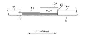
図6は、一実施形態における、モールド上における樹脂含浸繊維シート21の積層の様子を示す断面図である。同図に示すように、モールドM上には、モールドMの長手方向に沿って配置されたコア材64間に溝65が形成されている。樹脂含浸繊維シート21は、積層装置200によって、溝65内に積層される。この際、モールドMの幅方向に複数列に並べて、樹脂含浸繊維シート21を積層してもよい。
また、積層装置200を用いて樹脂含浸繊維シート21を積層すると、クランプ206とは反対側の樹脂含浸繊維シート21の端部において、積層された樹脂含浸繊維シート21の全体厚さtだけ段差が形成されることになる。かかる段差が風車翼50の品質に及ぼす影響が懸念される場合、該段差周辺をパテで埋めて、該段差になだらかに繋がる緩やかな傾斜面を形成してもよい。 In some embodiments, the laminating operation of the resin-impregnated
FIG. 6 is a cross-sectional view showing a state of lamination of the resin-impregnated
Further, when the resin-impregnated
図7は、複数台の積層装置200を使用した樹脂含浸繊維シート21の積層作業の様子を示す図である。同図に示すように、先行する積層装置200-1によって、モールドM上に樹脂含浸繊維シート21-1がモールドM上に載置された後、後行する積層装置200-2によって樹脂含浸繊維シート21-2が樹脂含浸繊維シート21-1上に積み重ねられる。このように、積層装置200を複数台使用すれば、樹脂含浸繊維シート21のモールドM上への積層作業のサイクルタイムを短縮でき、風車翼の生産効率がより一層向上する。 In some embodiments, the laminating operation of the resin-impregnated
FIG. 7 is a view showing a state of the laminating operation of the resin-impregnated
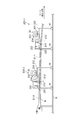
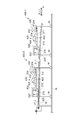
図8は、一実施形態に係る、強化繊維シートのロールを形成するための装置(ロール形成装置)の斜視図である。図9Aは、一実施形態に係る、強化繊維シートに樹脂を含浸させながらモールドに積層するための装置(積層装置)の平面図、図9Bは積層装置の側面図である。なお、図8において、図3に示すロール形成装置100と同一の部分については共通の符号を付して、その説明を適宜省略する。同様に、図9A及びに図9Bおいて、図5A及び図5Bに示す積層装置200と同一の部分については共通の符号を付して、その説明を適宜省略する。 In some embodiments, the reinforcing fiber sheet obtained by step S4 in FIG. 1 is wound on a bobbin to form a roll of reinforcing fiber sheet, and in steps S6 and S8, the reinforcing fiber sheet is pulled out of the roll and the reinforcing fiber sheet is pulled out. The fiber sheet is laminated on the mold while impregnating the resin with the resin.
FIG. 8 is a perspective view of an apparatus (roll forming apparatus) for forming a roll of reinforcing fiber sheets according to an embodiment. FIG. 9A is a plan view of an apparatus (laminating apparatus) for laminating a reinforcing fiber sheet into a mold while impregnating a resin, and FIG. 9B is a side view of the laminating apparatus. In FIG. 8, the same parts as those of the
ロール形成装置300は、図3に示すロール形成装置100から含浸ユニット20及び樹脂量調節ユニット26を省略したものに相当する。よって、ロール形成装置300により最終的に得られるのは、下流側挟持部8を通過した強化繊維シート3をボビン331に巻き取って形成した強化繊維シート3のロール330である。
なお、ロール形成装置300は、下流側挟持部8よりも上流側の構成は図3に示すロール形成装置100と同様である。すなわち、ロール形成装置300では、上流側から順に、繊維束2が巻き取られたボビン1、ロービングガイド4、上流側挟持部6、圧縮気体吐出ユニット10、下流側挟持部8が設けられている。なお、幾つかの実施形態では、下流側挟持部8を構成するローラ8A,8Bの少なくとも一方が振動し、圧縮気体吐出ユニット10による繊維束2の開繊を補助するようになっている。また、他の実施形態では、圧縮気体吐出ユニット10を設けずに、下流側挟持部8のローラ8A,8Bの少なくとも一方の振動によって繊維束2の開繊を行う。さらに別の実施形態では、上流側挟持部6と下流側挟持部8との間に、繊維束2の開繊を行うための振動ローラが別途設けられる。 A
The
The
積層装置400は、図5A及び図5Bに示す積層装置200に含浸ユニット420を追加したものに相当する。すなわち、積層装置400では、ロール330から引き出された強化繊維シート3に熱硬化性樹脂23を含浸させるための含浸ユニット420がロール330とシート位置調整ローラ210との間に設けられている。 The
The
なお、樹脂バス422に貯留される熱硬化性樹脂23は、液状且つ無溶剤であり、硬化剤を添加した直後における温度条件40℃での粘度が例えば50~150mPa・s(典型的には約90mPa・s)である。なお、硬化剤添加後の熱硬化性樹脂23は、時間経過とともに徐々に粘度が上昇してもよい。 In some embodiments, the
The
なお、熱硬化性樹脂23又は強化繊維シート3の温度の設定値は、例えば35~60℃の範囲内から適宜選択される温度である。この設定値は、熱硬化性樹脂23の粘度や強化繊維シート3との親和性に応じて、強化繊維シート3への熱硬化性樹脂23の含浸が適切に行われるように決定されてもよい。例えば、強化繊維シート3への含浸時における熱硬化性樹脂23の粘度30~170Pa・sが実現されるように、熱硬化性樹脂23又は強化繊維シート3の温度の設定値が決定される。 In one embodiment, the temperature of the
The set value of the temperature of the
図10は、複数台の積層装置400を使用した強化繊維シート3への樹脂含浸作業および樹脂含浸繊維シート21の積層作業の様子を示す図である。同図に示すように、先行する積層装置400-1によって、強化繊維シート3-1に熱硬化性樹脂23を含浸させて樹脂含浸繊維シート21-1を形成し、モールドM上に樹脂含浸繊維シート21-1を載置する。さらに、後行する積層装置400-2によって、強化繊維シート3-2に熱硬化性樹脂23を含浸させて樹脂含浸繊維シート21-2を形成し、樹脂含浸繊維シート21-1上に樹脂含浸繊維シート21-2を積み重ねる。このように、積層装置400を複数台使用すれば、強化繊維シート3への熱硬化性樹脂23の含浸および樹脂含浸繊維シート21のモールドM上への積層作業のサイクルタイムを短縮でき、風車翼の生産効率がより一層向上する。 In some embodiments, using a plurality of
FIG. 10 is a view showing a state of the resin impregnation work on the reinforcing
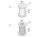
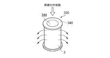
図11A及び図11Bは、実施形態に係るボビン331を示す斜視図である。図12は、強化繊維シート3をボビン331に巻いた状態のまま、熱硬化性樹脂23の強化繊維シート3への含浸を行う様子を示す図である。
ボビン331の芯部340には開口342が設けられている。開口342は、図11Aに示すように芯部340に穿孔された多数の貫通穴であってもよいし、図11Bに示すように網目状の芯部340に多数の貫通穴であってもよい。
図12に示すように、ロール330の芯部340の内側空間344に熱硬化性樹脂23を注入し、芯部340に設けられた開口342を介して強化繊維シート3に熱硬化性樹脂23を含浸させる。こうして、樹脂含浸繊維シート21が得られる。
これにより、強化繊維シート3への熱硬化性樹脂23の含浸を迅速に行うことができる。さらに、熱硬化性樹脂23の含浸前の強化繊維シート3のロール330は常温でも長期に亘る保存が可能であり、ロール330の長期保存のための冷蔵などの処置を必要としないため、コスト削減につながる。 In one embodiment, the impregnation of the
11A and 11B are perspective views showing a
An
As shown in FIG. 12, the
Thereby, the impregnation of the
このように、ロール330の強化繊維シート3の層間に剥離シートを介在させておくことで、ロール330の内側空間344への熱硬化性樹脂23の注入によって得られる樹脂含浸繊維シート21の層間の接着を防止できる。 In order to prevent adhesion between the layers of the resin-impregnated
In this way, by interposing the release sheet between the layers of the reinforcing
また、熱硬化性樹脂23は、液状であるため強化繊維シート3への含浸性が良好であり、かつ、無溶剤であるため溶剤揮発工程を省略できる。さらに、熱硬化性樹脂23が未硬化の状態である樹脂含浸繊維シート21をモールドM上に配置して風車翼の成形を行うから、成形時における熱硬化性樹脂23の流動性が良好であり、高品質な風車翼を得ることができる。 As described above, in the above-described embodiment, the wind turbine blade is used by using the resin-impregnated
Moreover, since the
2 繊維束
3 強化繊維シート
4 ロービングガイド
6 上流側挟持部
8 下流側挟持部
10 圧縮気体吐出ユニット
12 ノズル
14 可動部
16 静止部
20 含浸ユニット
21 樹脂含浸繊維シート
22 樹脂バス
23 熱硬化性樹脂
24 含浸ローラ
26 樹脂量調節ユニット
30 ロール
31 ボビン
50 風車翼
52 前縁接合面
54 後縁接合面
60 腹側部
62 背側部
64 コア材
66 スパーキャップ
68 スパー(シアウェブ)
100 ロール形成装置
200 積層装置
202 フレーム
203 回転軸
204 テンションローラ
206 クランプ
210 シート位置調整ローラ
212 回動軸
220 シート押付ローラ
222 付勢部材
300 ロール形成装置
330 ロール
331 ボビン
340 芯部
342 開口
344 内側空間
400 積層装置
420 含浸ユニット
422 樹脂バス
424 含浸ローラ DESCRIPTION OF
DESCRIPTION OF
Claims (12)
- 少なくとも一部が繊維強化プラスチックで構成された風車翼の製造方法であって、
複数のボビンからそれぞれ複数本の強化繊維の繊維束を引き出すステップと、
各ボビンから引き出された複数本の前記繊維束を並べ、該繊維束を開繊して隣接する前記繊維束をオーバーラップさせ、複数本の前記繊維束から強化繊維シートを得るステップと、
前記強化繊維シートに無溶剤かつ液状の熱硬化性樹脂を含浸させ、前記強化繊維と未硬化の前記熱硬化性樹脂とを含んで構成される樹脂含浸繊維シートを形成するステップと、
前記熱硬化性樹脂が未硬化の状態である前記樹脂含浸繊維シートをモールド上に配置し、該モールド上において前記樹脂含浸繊維シートの前記熱硬化性樹脂を加熱硬化して、前記風車翼の成形を行うステップとを備えることを特徴とする風車翼の製造方法。 A method for manufacturing a wind turbine blade at least partially made of fiber reinforced plastic,
Pulling out a bundle of reinforcing fibers from a plurality of bobbins,
Arranging the plurality of fiber bundles drawn from each bobbin, opening the fiber bundle to overlap adjacent fiber bundles, and obtaining a reinforcing fiber sheet from the plurality of fiber bundles;
Impregnating the reinforcing fiber sheet with a solvent-free and liquid thermosetting resin to form a resin-impregnated fiber sheet comprising the reinforcing fiber and the uncured thermosetting resin;
The resin impregnated fiber sheet in an uncured state of the thermosetting resin is placed on a mold, and the thermosetting resin of the resin impregnated fiber sheet is heated and cured on the mold to form the wind turbine blade. A method for manufacturing a wind turbine blade. - 前記強化繊維シートを得るステップでは、一対のローラをそれぞれ含む上流側挟持部と下流側挟持部とによって、連続的に搬送される複数本の前記繊維束を挟持しながら、前記上流側挟持部と前記下流側挟持部との間において前記繊維束の開繊を行うとともに、
前記上流側挟持部と前記下流側挟持部との前記ローラの周速を一致させたことを特徴とする請求項1に記載の風車翼の製造方法。 In the step of obtaining the reinforcing fiber sheet, the upstream clamping unit and the downstream clamping unit each including a pair of rollers while sandwiching the plurality of fiber bundles that are continuously conveyed, While performing the opening of the fiber bundle between the downstream clamping unit,
The method for manufacturing a wind turbine blade according to claim 1, wherein peripheral speeds of the rollers of the upstream clamping unit and the downstream clamping unit are matched. - 前記強化繊維シートを得るステップでは、並べられた複数本の前記繊維束に対向するように前記上流側挟持部と前記下流側挟持部との間に配置された少なくとも一つのノズルを前記強化繊維シートの幅方向に往復運動させながら、前記ノズルから噴射される圧縮気体によって前記繊維束の開繊を行うことを特徴とする請求項2に記載の風車翼の製造方法。 In the step of obtaining the reinforcing fiber sheet, the reinforcing fiber sheet is provided with at least one nozzle disposed between the upstream clamping portion and the downstream clamping portion so as to face the plurality of arranged fiber bundles. The method for manufacturing a wind turbine blade according to claim 2, wherein the fiber bundle is opened by compressed gas ejected from the nozzle while reciprocating in the width direction.
- 前記強化繊維シートを得るステップでは、前記下流側挟持部の前記ローラの少なくとも一方を振動させて、前記繊維束の開繊を行うことを特徴とする請求項2に記載の風車翼の製造方法。 3. The method of manufacturing a wind turbine blade according to claim 2, wherein in the step of obtaining the reinforcing fiber sheet, at least one of the rollers of the downstream-side clamping unit is vibrated to open the fiber bundle.
- 前記強化繊維シートを得るステップでは、前記強化繊維シートの幅方向に前記ローラを振動させることを特徴とする請求項4に記載の風車翼の製造方法。 The method for manufacturing a wind turbine blade according to claim 4, wherein in the step of obtaining the reinforcing fiber sheet, the roller is vibrated in a width direction of the reinforcing fiber sheet.
- 前記樹脂含浸繊維シートを形成するステップでは、未硬化の前記熱硬化性樹脂を前記強化繊維シートに含浸させた後、一対のローラで前記樹脂含浸繊維シートを挟持して、前記樹脂含浸繊維シートにおける未硬化の前記熱硬化性樹脂の含有量を調節することを特徴とする請求項1に記載の風車翼の製造方法。 In the step of forming the resin-impregnated fiber sheet, after impregnating the reinforcing fiber sheet with the uncured thermosetting resin, the resin-impregnated fiber sheet is sandwiched by a pair of rollers, The method for manufacturing a wind turbine blade according to claim 1, wherein the content of the uncured thermosetting resin is adjusted.
- 前記樹脂含浸繊維シートをボビンに巻き取って、前記樹脂含浸繊維シートの少なくとも一つのロールを形成するステップをさらに備え、
前記風車翼の成形を行うステップでは、前記ロールから前記樹脂含浸繊維シートを引き出して、前記モールド上に前記樹脂含浸繊維シートを積層することを特徴とする請求項1に記載の風車翼の製造方法。 Winding the resin-impregnated fiber sheet around a bobbin to further form at least one roll of the resin-impregnated fiber sheet;
2. The method for manufacturing a wind turbine blade according to claim 1, wherein in the step of forming the wind turbine blade, the resin impregnated fiber sheet is pulled out from the roll and the resin impregnated fiber sheet is laminated on the mold. . - 前記風車翼の成形を行うステップでは、前記ロールの前記樹脂含浸繊維シートの一端をクランプによって固定した状態で、前記ロールが取り付けられたカートを前記モールドの長手方向に沿って前記クランプから遠ざかるように移動させ、前記カートに取り付けられた少なくとも一つのローラによって前記ロールから引き出された前記樹脂含浸繊維シートを前記モールドに押し付けることを特徴とする請求項7に記載の風車翼の製造方法。 In the step of forming the wind turbine blade, in a state where one end of the resin-impregnated fiber sheet of the roll is fixed by a clamp, the cart attached with the roll is moved away from the clamp along the longitudinal direction of the mold. The method for manufacturing a wind turbine blade according to claim 7, wherein the resin impregnated fiber sheet is moved and pressed against the mold by at least one roller attached to the cart.
- 前記強化繊維シートをボビンに巻き取って、前記強化繊維シートのロールを形成するステップをさらに備え、
前記樹脂含浸繊維シートを形成するステップでは、前記ロールの前記強化繊維シートの一端をクランプによって固定した状態で、前記強化繊維シートがボビンに巻き取られたロールが取り付けられたカートを前記モールドの長手方向に沿って前記クランプから遠ざかるように移動させ、前記ロールから前記強化繊維シートを引き出しながら、前記カートに設けられた含浸ユニットにより前記強化繊維シートに未硬化の前記熱硬化性樹脂を含浸させて前記樹脂含浸繊維シートを形成し、
前記風車翼の成形を行うステップでは、前記カートに取り付けられた少なくとも一つのローラによって前記含浸ユニット側から搬送される前記樹脂含浸繊維シートを前記モールドに押し付けることを特徴とする請求項1に記載の風車翼の製造方法。 Winding the reinforcing fiber sheet around a bobbin to further form a roll of the reinforcing fiber sheet;
In the step of forming the resin-impregnated fiber sheet, in a state where one end of the reinforcing fiber sheet of the roll is fixed by a clamp, a cart attached with a roll having the reinforcing fiber sheet wound around a bobbin is attached to the length of the mold. Moving away from the clamp along the direction, and withdrawing the reinforcing fiber sheet from the roll, the reinforcing fiber sheet is impregnated with the uncured thermosetting resin by an impregnation unit provided in the cart. Forming the resin-impregnated fiber sheet;
2. The resin impregnated fiber sheet conveyed from the impregnation unit side is pressed against the mold by at least one roller attached to the cart in the step of forming the wind turbine blade. A method of manufacturing a wind turbine blade. - 前記樹脂含浸繊維シートを形成するステップでは、前記強化繊維で構成された強化繊維シートがボビンに巻き取られたロールの前記ボビンの芯部の内側空間に前記熱硬化性樹脂を注入し、前記芯部に設けられた開口を介して前記強化繊維シートに前記熱硬化性樹脂を含浸させることを特徴とする請求項1に記載の風車翼の製造方法。 In the step of forming the resin-impregnated fiber sheet, the thermosetting resin is injected into the inner space of the core portion of the bobbin of the roll in which the reinforcing fiber sheet composed of the reinforcing fibers is wound around the bobbin, and the core The method for manufacturing a wind turbine blade according to claim 1, wherein the thermosetting resin is impregnated in the reinforcing fiber sheet through an opening provided in a portion.
- 前記風車翼の成形を行うステップでは、前記モールド上に該モールドの長手方向に沿って配置された前記風車翼の一対のコア材の間に前記樹脂含浸繊維シートを配置し、該モールド上において前記樹脂含浸繊維シートの前記熱硬化性樹脂を加熱硬化することで、一対の前記コア材に挟まれた前記風車翼のスパーキャップを形成することを特徴とする請求項1に記載の風車翼の製造方法。 In the step of forming the windmill blade, the resin-impregnated fiber sheet is disposed on the mold between a pair of core materials of the windmill blade disposed along the longitudinal direction of the mold, and the mold is disposed on the mold. 2. The wind turbine blade manufacturing method according to claim 1, wherein a spar cap of the wind turbine blade sandwiched between a pair of the core members is formed by heat curing the thermosetting resin of the resin-impregnated fiber sheet. Method.
- 前記繊維強化プラスチックは、前記強化繊維としての炭素繊維を含むCFRPであることを特徴とする請求項1に記載の風車翼の製造方法。
The method for manufacturing a wind turbine blade according to claim 1, wherein the fiber-reinforced plastic is CFRP containing carbon fibers as the reinforcing fibers.
Priority Applications (3)
| Application Number | Priority Date | Filing Date | Title |
|---|---|---|---|
| JP2014536526A JP5925325B2 (en) | 2012-09-24 | 2012-09-24 | Wind turbine blade manufacturing method |
| PCT/JP2012/074351 WO2014045429A1 (en) | 2012-09-24 | 2012-09-24 | Method for manufacturing windmill blade |
| EP12885167.2A EP2899396B1 (en) | 2012-09-24 | 2012-09-24 | Method for manufacturing windmill blade |
Applications Claiming Priority (1)
| Application Number | Priority Date | Filing Date | Title |
|---|---|---|---|
| PCT/JP2012/074351 WO2014045429A1 (en) | 2012-09-24 | 2012-09-24 | Method for manufacturing windmill blade |
Publications (1)
| Publication Number | Publication Date |
|---|---|
| WO2014045429A1 true WO2014045429A1 (en) | 2014-03-27 |
Family
ID=50340779
Family Applications (1)
| Application Number | Title | Priority Date | Filing Date |
|---|---|---|---|
| PCT/JP2012/074351 WO2014045429A1 (en) | 2012-09-24 | 2012-09-24 | Method for manufacturing windmill blade |
Country Status (3)
| Country | Link |
|---|---|
| EP (1) | EP2899396B1 (en) |
| JP (1) | JP5925325B2 (en) |
| WO (1) | WO2014045429A1 (en) |
Cited By (3)
| Publication number | Priority date | Publication date | Assignee | Title |
|---|---|---|---|---|
| US9822761B2 (en) | 2014-08-13 | 2017-11-21 | General Electric Company | Structural components and methods of manufacturing |
| WO2019055184A1 (en) * | 2017-09-14 | 2019-03-21 | General Electric Company | Method and system for forming fiber-reinforced polymer components |
| KR20230041999A (en) * | 2021-05-04 | 2023-03-27 | 두산에너빌리티 주식회사 | Blade of wind turbine and manufacturing method of the same |
Citations (10)
| Publication number | Priority date | Publication date | Assignee | Title |
|---|---|---|---|---|
| JPS52151362A (en) * | 1976-06-11 | 1977-12-15 | Nippon Carbon Co Ltd | Arranged preepreg and its manufacture |
| JPS62135537A (en) * | 1985-12-09 | 1987-06-18 | Fuji Standard Res Kk | Flexible composite material and production thereof |
| JPH0899365A (en) * | 1994-09-30 | 1996-04-16 | Sekisui Chem Co Ltd | Manufacture of fiber reinforced resin molded body |
| US6094791A (en) * | 1997-04-10 | 2000-08-01 | Toray Industries, Inc. | Method and apparatus for opening reinforcing fiber bundle and method of manufacturing prepreg |
| JP2002363855A (en) * | 2001-06-07 | 2002-12-18 | Toray Ind Inc | Opening device and opening method for fiber bundle and method for producing prepreg |
| JP2006232915A (en) * | 2005-02-23 | 2006-09-07 | Dainippon Ink & Chem Inc | Epoxy resin composition for frp |
| JP2008290331A (en) * | 2007-05-24 | 2008-12-04 | Asahi Kasei Electronics Co Ltd | Method for production of prepreg |
| US20120009069A1 (en) | 2010-07-09 | 2012-01-12 | Erik Grove-Nielsen | Method to manufacture a component of a composite structure |
| JP2012086564A (en) * | 2010-10-12 | 2012-05-10 | General Electric Co <Ge> | Composite components, and processes therefor |
| JP2012153839A (en) * | 2011-01-27 | 2012-08-16 | Fukui Prefecture | Molded article for flying object or windmill |
Family Cites Families (11)
| Publication number | Priority date | Publication date | Assignee | Title |
|---|---|---|---|---|
| US4532169A (en) * | 1981-10-05 | 1985-07-30 | Ppg Industries, Inc. | High performance fiber ribbon product, high strength hybrid composites and methods of producing and using same |
| JPH03251408A (en) * | 1990-02-28 | 1991-11-08 | Sekisui Chem Co Ltd | Method of impregnating resin into continuous reinforcing fiber |
| FR2761380B1 (en) * | 1997-03-28 | 1999-07-02 | Europ Propulsion | METHOD AND MACHINE FOR PRODUCING MULTIAXIAL FIBROUS MATS |
| US6096669A (en) * | 1997-10-28 | 2000-08-01 | Gkn Westland Aerospace Inc. | Unidirectional fiber-random mat preform |
| JP4461565B2 (en) * | 2000-04-25 | 2010-05-12 | 日東紡績株式会社 | Manufacturing apparatus and manufacturing method of long glass fiber pellet |
| JP2002212886A (en) * | 2001-01-05 | 2002-07-31 | Toyobo Co Ltd | Method for modifying molding from rigid chain polymer solution |
| JP2005163223A (en) * | 2003-12-03 | 2005-06-23 | Toray Ind Inc | Method and apparatus for opening reinforcing fiber bundle |
| US7976282B2 (en) * | 2007-01-26 | 2011-07-12 | General Electric Company | Preform spar cap for a wind turbine rotor blade |
| FR2928294B1 (en) * | 2008-03-07 | 2016-12-30 | Duqueine Rhone Alpes | METHOD AND DEVICE FOR MAKING A CURVED PROFILE OF COMPOSITE MATERIAL, AND CORRESPONDING PROFILE |
| JP5078757B2 (en) * | 2008-05-30 | 2012-11-21 | 三菱重工業株式会社 | Wind turbine blade and method for manufacturing wind turbine blade |
| JP5569142B2 (en) * | 2010-05-20 | 2014-08-13 | トヨタ自動車株式会社 | Prepreg manufacturing apparatus and prepreg manufacturing method |
-
2012
- 2012-09-24 EP EP12885167.2A patent/EP2899396B1/en active Active
- 2012-09-24 WO PCT/JP2012/074351 patent/WO2014045429A1/en active Application Filing
- 2012-09-24 JP JP2014536526A patent/JP5925325B2/en active Active
Patent Citations (11)
| Publication number | Priority date | Publication date | Assignee | Title |
|---|---|---|---|---|
| JPS52151362A (en) * | 1976-06-11 | 1977-12-15 | Nippon Carbon Co Ltd | Arranged preepreg and its manufacture |
| JPS62135537A (en) * | 1985-12-09 | 1987-06-18 | Fuji Standard Res Kk | Flexible composite material and production thereof |
| JPH0899365A (en) * | 1994-09-30 | 1996-04-16 | Sekisui Chem Co Ltd | Manufacture of fiber reinforced resin molded body |
| US6094791A (en) * | 1997-04-10 | 2000-08-01 | Toray Industries, Inc. | Method and apparatus for opening reinforcing fiber bundle and method of manufacturing prepreg |
| JP2002363855A (en) * | 2001-06-07 | 2002-12-18 | Toray Ind Inc | Opening device and opening method for fiber bundle and method for producing prepreg |
| JP2006232915A (en) * | 2005-02-23 | 2006-09-07 | Dainippon Ink & Chem Inc | Epoxy resin composition for frp |
| JP2008290331A (en) * | 2007-05-24 | 2008-12-04 | Asahi Kasei Electronics Co Ltd | Method for production of prepreg |
| US20120009069A1 (en) | 2010-07-09 | 2012-01-12 | Erik Grove-Nielsen | Method to manufacture a component of a composite structure |
| JP2012016948A (en) * | 2010-07-09 | 2012-01-26 | Siemens Ag | Method for manufacturing component of composite structure |
| JP2012086564A (en) * | 2010-10-12 | 2012-05-10 | General Electric Co <Ge> | Composite components, and processes therefor |
| JP2012153839A (en) * | 2011-01-27 | 2012-08-16 | Fukui Prefecture | Molded article for flying object or windmill |
Non-Patent Citations (1)
| Title |
|---|
| See also references of EP2899396A4 |
Cited By (6)
| Publication number | Priority date | Publication date | Assignee | Title |
|---|---|---|---|---|
| US9822761B2 (en) | 2014-08-13 | 2017-11-21 | General Electric Company | Structural components and methods of manufacturing |
| DK179320B1 (en) * | 2014-08-13 | 2018-04-30 | Gen Electric | PROCEDURES FOR MANUFACTURING A STRUCTURAL COMPONENT |
| WO2019055184A1 (en) * | 2017-09-14 | 2019-03-21 | General Electric Company | Method and system for forming fiber-reinforced polymer components |
| US10688737B2 (en) | 2017-09-14 | 2020-06-23 | General Electric Company | Method for forming fiber-reinforced polymer components |
| KR20230041999A (en) * | 2021-05-04 | 2023-03-27 | 두산에너빌리티 주식회사 | Blade of wind turbine and manufacturing method of the same |
| KR102586818B1 (en) * | 2021-05-04 | 2023-10-06 | 두산에너빌리티 주식회사 | Blade of wind turbine and manufacturing method of the same |
Also Published As
| Publication number | Publication date |
|---|---|
| JP5925325B2 (en) | 2016-05-25 |
| EP2899396B1 (en) | 2017-08-16 |
| EP2899396A4 (en) | 2016-06-15 |
| JPWO2014045429A1 (en) | 2016-08-18 |
| EP2899396A1 (en) | 2015-07-29 |
Similar Documents
| Publication | Publication Date | Title |
|---|---|---|
| WO2017022607A1 (en) | Production method for fiber reinforced resin sheet material | |
| JP5551411B2 (en) | Case manufacturing method and case | |
| JPS63189235A (en) | Method and device for winding crossing tape | |
| KR20090125766A (en) | Round fiber-reinforced plastic wire, process for producing the same, and fiber-reinforced sheet | |
| JP2015534914A (en) | Method for producing a fiber preform | |
| JP6185350B2 (en) | Prepreg automatic laminating apparatus, prepreg laminated body manufacturing method, and fiber reinforced composite material manufacturing apparatus | |
| JP5609249B2 (en) | High pressure tank manufacturing method, high pressure tank manufacturing apparatus, and high pressure tank | |
| JP5925325B2 (en) | Wind turbine blade manufacturing method | |
| JP2012131874A (en) | Fiber-reinforced flat plastic wire, method for manufacturing the same, and fiber-reinforced sheet | |
| US20160339650A1 (en) | Manufacturing method of tank and tank manufacturing apparatus | |
| JP2016215496A (en) | Method and apparatus for manufacturing tank | |
| WO2015005493A1 (en) | Flat fiber-reinforced plastic strand, flat fiber-reinforced plastic-strand sheet, and production method for same | |
| JP2007203723A (en) | Tube made of fiber-reinforced plastic, and its manufacturing method | |
| JP2006192727A (en) | Tubular body made of carbon fiber-reinforced plastic and its manufacturing method | |
| JP2018534183A (en) | Thermoplastic composite in situ melt processing method for composite overlap tool | |
| JP3635773B2 (en) | Yarn prepreg manufacturing method and apparatus | |
| JP5569142B2 (en) | Prepreg manufacturing apparatus and prepreg manufacturing method | |
| JP4156620B2 (en) | Prepreg manufacturing apparatus and prepreg | |
| AU2016219741B2 (en) | A method and system for fabricating a composite structure | |
| JP5251723B2 (en) | Resin impregnation equipment and high pressure gas tank production equipment | |
| JP2005324513A (en) | Apparatus for continuously manufacturing preform of girder material made of frp | |
| EP2868452B1 (en) | System and method for producing composite component | |
| TW201636195A (en) | Production of locally reinforced fibre composite components for mass production in a continuous process | |
| JP4973168B2 (en) | Fiber reinforced composite material molding equipment | |
| JPH11114953A (en) | Manufacture of prepreg and device therefor |
Legal Events
| Date | Code | Title | Description |
|---|---|---|---|
| 121 | Ep: the epo has been informed by wipo that ep was designated in this application |
Ref document number: 12885167 Country of ref document: EP Kind code of ref document: A1 |
|
| ENP | Entry into the national phase |
Ref document number: 2014536526 Country of ref document: JP Kind code of ref document: A |
|
| REEP | Request for entry into the european phase |
Ref document number: 2012885167 Country of ref document: EP |
|
| WWE | Wipo information: entry into national phase |
Ref document number: 2012885167 Country of ref document: EP |
|
| NENP | Non-entry into the national phase |
Ref country code: DE |