WO2014045352A1 - 農作物の展示装置及びこれを用いた販売機 - Google Patents
農作物の展示装置及びこれを用いた販売機 Download PDFInfo
- Publication number
- WO2014045352A1 WO2014045352A1 PCT/JP2012/073933 JP2012073933W WO2014045352A1 WO 2014045352 A1 WO2014045352 A1 WO 2014045352A1 JP 2012073933 W JP2012073933 W JP 2012073933W WO 2014045352 A1 WO2014045352 A1 WO 2014045352A1
- Authority
- WO
- WIPO (PCT)
- Prior art keywords
- support base
- window
- display apparatus
- agricultural product
- product display
- Prior art date
- Legal status (The legal status is an assumption and is not a legal conclusion. Google has not performed a legal analysis and makes no representation as to the accuracy of the status listed.)
- Ceased
Links
Images





Classifications
-
- A—HUMAN NECESSITIES
- A47—FURNITURE; DOMESTIC ARTICLES OR APPLIANCES; COFFEE MILLS; SPICE MILLS; SUCTION CLEANERS IN GENERAL
- A47F—SPECIAL FURNITURE, FITTINGS, OR ACCESSORIES FOR SHOPS, STOREHOUSES, BARS, RESTAURANTS OR THE LIKE; PAYING COUNTERS
- A47F3/00—Show cases or show cabinets
-
- A—HUMAN NECESSITIES
- A47—FURNITURE; DOMESTIC ARTICLES OR APPLIANCES; COFFEE MILLS; SPICE MILLS; SUCTION CLEANERS IN GENERAL
- A47F—SPECIAL FURNITURE, FITTINGS, OR ACCESSORIES FOR SHOPS, STOREHOUSES, BARS, RESTAURANTS OR THE LIKE; PAYING COUNTERS
- A47F7/00—Show stands, hangers, or shelves, adapted for particular articles or materials
- A47F7/0071—Show stands, hangers, or shelves, adapted for particular articles or materials for perishable goods
-
- G—PHYSICS
- G07—CHECKING-DEVICES
- G07F—COIN-FREED OR LIKE APPARATUS
- G07F11/00—Coin-freed apparatus for dispensing, or the like, discrete articles
- G07F11/62—Coin-freed apparatus for dispensing, or the like, discrete articles in which the articles are stored in compartments in fixed receptacles
-
- G—PHYSICS
- G07—CHECKING-DEVICES
- G07F—COIN-FREED OR LIKE APPARATUS
- G07F9/00—Details other than those peculiar to special kinds or types of apparatus
- G07F9/10—Casings or parts thereof, e.g. with means for heating or cooling
-
- A—HUMAN NECESSITIES
- A47—FURNITURE; DOMESTIC ARTICLES OR APPLIANCES; COFFEE MILLS; SPICE MILLS; SUCTION CLEANERS IN GENERAL
- A47F—SPECIAL FURNITURE, FITTINGS, OR ACCESSORIES FOR SHOPS, STOREHOUSES, BARS, RESTAURANTS OR THE LIKE; PAYING COUNTERS
- A47F11/00—Arrangements in shop windows, shop floors or show cases
- A47F11/06—Means for bringing about special optical effects
-
- A—HUMAN NECESSITIES
- A47—FURNITURE; DOMESTIC ARTICLES OR APPLIANCES; COFFEE MILLS; SPICE MILLS; SUCTION CLEANERS IN GENERAL
- A47F—SPECIAL FURNITURE, FITTINGS, OR ACCESSORIES FOR SHOPS, STOREHOUSES, BARS, RESTAURANTS OR THE LIKE; PAYING COUNTERS
- A47F3/00—Show cases or show cabinets
- A47F3/04—Show cases or show cabinets air-conditioned, refrigerated
- A47F3/0404—Cases or cabinets of the closed type
- A47F3/0426—Details
- A47F3/043—Doors, covers
Definitions
- the present invention relates to an agricultural product display device for displaying agricultural products, for example, and a vending machine using the same.
- Each of the crops to be sold is placed in a plurality of product sections, and a binding policy is attached to each crop.
- a crop vending machine has been proposed in which a user can obtain the crop after releasing the binding policy (see Patent Document 1).
- an object of the present invention is to provide, for example, a crop display apparatus that can satisfactorily display crops and a vending machine using the same.
- the agricultural product display apparatus is supported by a support base and the support base, and accommodates the crop between the support base.
- a transparent window portion constituting the space and an opening / closing mechanism for opening and closing the window portion are provided.
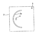
- the crop display apparatus which concerns on the 1st Embodiment of this invention is shown, (A) is a perspective view, (B) is sectional drawing. It is a top view of the support stand in the display apparatus of FIG.
- the window part in the display apparatus of FIG. 1 is shown, (A) is a front view of a window part, (B) is a bottom view of a window part. It is a figure explaining the usage of the display apparatus of FIG. 1, (A) shows the state figure before utilization start, (B) shows the state figure at the time of crop extraction.
- the crop display apparatus which concerns on the 2nd Embodiment of this invention is shown, (A) is a state figure before a window part opening, (B) is a state figure after a window part opening.
- the crop display apparatus which concerns on the 3rd Embodiment of this invention is shown, (A) is a state figure before a window part opening, (B) is a state figure after a window part opening. It is a fragmentary sectional view of the window part in the display device of agricultural products concerning a 4th embodiment of the present invention.
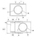
- the crop display apparatus which concerns on the 5th Embodiment of this invention is shown, (A) is a top view before support stand movement, (B) is a top view after support stand movement. It is sectional drawing of the display apparatus of the crop concerning the 6th Embodiment of this invention. It is explanatory drawing of the crop which concerns on the 7th Embodiment of this invention. It is a schematic explanatory drawing of the vending machine to which the display device of agricultural products of the present invention is applied.
- An agricultural product display apparatus includes a support base, a transparent window portion that is supported by the support base, and that forms a space for accommodating the crop between the support base, and an opening / closing mechanism that opens and closes the window portion. It is characterized by having.
- the window is preferably made of resin. Thereby, a window part can be produced easily.
- the resin preferably has a light guiding property. Thereby, the space which accommodates agricultural products can be brightened.
- the resin is preferably an acrylic resin.
- the window portion can have light guiding properties, and the space for storing the crops can be brightened.
- the window portion preferably includes a dome-shaped storage portion. Thereby, it can suppress that a window part is damaged by contact with a support stand and a window part with opening and closing of a window part. Moreover, you may form a dome shape storage part along a virtual spherical surface.
- the thickness at the outer peripheral portion of the dome-shaped storage portion facing the support base is larger than the thickness at the center portion of the dome-shaped storage portion. Therefore, it can suppress that damage arises in a window part.
- the flange portion is relatively thick, more light emitted from the lighting or the like can be taken in, and the space for storing the crop can be brightened.
- the thickness of the flange portion described later may be larger than the thickness of the dome-shaped storage portion.
- the window portion is rotatable with respect to the support base, and the rotation axis of the window portion passes through two different portions in the window portion, and the two different portions are located at substantially the same height as each other and are opposed to each other. It is preferable to arrange
- the window portion may be substantially parallel to the support base, have an axis through which the axis passes through the center of the phantom spherical surface, and may be rotatable with respect to the support base about the axis as a rotation axis when opening and closing.
- the window portion includes a first window portion and a second window portion, the second window portion is rotatable with respect to the support base along the first window portion, and the rotation axis of the second window portion. Passes through two different parts of the window, and the two different parts may be located at substantially the same height as each other and may be disposed at opposing positions. Thereby, the rotation range of a window part can be made comparatively large.
- the window portion has a rotation axis that is substantially parallel to the support base and has an axis passing through the center of the phantom spherical surface.
- the first window portion is rotatable with respect to the support stand by the rotation axis, and the first window portion. And a second window portion that can be rotated along the second window portion with respect to the support base.
- Magnifying means such as a convex lens is preferably provided in the window. Thereby, it is possible to enlarge and view the crop through the magnifier.
- the support base includes a first support base and a second support base supported so as to be movable with respect to the first support base.
- the second support base moves along the first support base. It doesn't matter. As a result, the moving second support base is drawn toward the user side, so that the user can see the crops nearby and can easily pick up the hand by opening the window.
- the window portion may be rotated with respect to the support base by the driving device, and the support base may include an opening into which a part of the window portion is inserted.
- the window portion can be rotated with respect to the support base by the driving device.
- a part of window part may be arrange
- the drive device may be a gear drive system or a belt drive system. Thereby, a window part can be rotated easily.
- a light source provided on the support base may be provided. By illuminating the crop with a light source, the visibility of the crop can be improved.
- the light source may be composed of organic EL (Electro-Luminescence).
- organic EL Electro-Luminescence
- fever which organic EL emits is lower than a light emitting diode (LED) etc., it is preferable also from the point which maintains the freshness of agricultural products.
- a vending machine including any of the exhibition apparatuses described above may be configured. Thereby, the vending machine which can purchase agricultural products simply is obtained.
- vending machine provided with the exhibition apparatus in any one of the above which has a rotating window part, a lock part which locks rotation of the window part, and a release part which cancels lock of the lock part.
- a highly secure vending machine capable of preventing crop theft can be obtained.
- FIG. 1A and 1B show an agricultural product display apparatus according to a first embodiment of the present invention, in which FIG. 1A is a perspective view and FIG. 1B is a cross-sectional view.
- the crop display device 1 includes a flat plate-like support base 2 having a semicircular arc opening 2 a and a window portion 3 supported by the support base 2.
- the support 2 is made of, for example, a resin such as milky white acrylic resin or wooden such as wood
- the window portion 3 is made of, for example, a resin such as a transparent acrylic resin.
- the window portion 3 has a predetermined height and outer diameter, a dome-shaped storage portion 3A formed along a virtual spherical surface, and a flange integrally formed on the outer periphery of the dome-shaped storage portion 3A. Part 3B.
- the shape is not limited thereto, and a shape such as a cube or a rectangular parallelepiped can be used as the storage portion of the window portion.
- the dome-shaped storage portion 3A gradually increases in thickness as it goes from the upper portion (center portion) to the lower portion (outer peripheral portion), and the flange portion 3B is thickest. Therefore, the flange portion 3B and the opening portion 2a are designed with a sufficient clearance.
- the flange portion 3B and the support base 2 come into contact with each other in the opening portion 2a. Even when the part 3B comes into contact with the surface of the support base (surface 2A described later), damage to the flange part 3B can be suppressed. Moreover, since the upper part (center part) of the dome-shaped storage part is formed thinner than the lower part (outer peripheral part), the user can more easily see the crop.
- the dome-shaped storage portion 3A can be formed without the flange portion 3B. In this case, the outer peripheral portion of the dome-shaped storage portion 3A is the thickest.
- a shaft 3C having a length substantially equal to the diameter of the dome-shaped storage portion 3A and a reinforcing bar 3D may be provided between the substantially middle portion of the shaft 3C and the flange portion 3B at the bottom of the window portion 3.
- the shaft 3C is supported by a shaft support portion 2C provided on the back surface 2B of the support base 2 so as to be parallel to the support base 2 and rotatable with respect to the support base 2, and its axis is centered on the virtual spherical surface. Passing through.
- the shaft 3C passes through two different portions in the window portion 3. These two parts are located at substantially the same height with respect to the support base 2 and are disposed at positions facing each other.
- a part of the flange portion 3 ⁇ / b> B of the window portion 3, the shaft 3 ⁇ / b> C, and the reinforcing rod 3 ⁇ / b> D are disposed on the back surface 2 ⁇ / b> B side of the support base 2.
- the remaining portion of the flange portion 3 ⁇ / b> B of the window portion 3 is located on the support base 2.
- the opening 2a of the support base 2 and the shaft 3C of the window 3 constitute an opening / closing mechanism.
- the window portion 3 is rotatable with respect to the support base 2 with the shaft 3 ⁇ / b> C as a rotation axis when opening and closing.
- a part of the outer peripheral portion of the window portion 3 is arranged on the back surface 2B side of the support base 2, and the other part of the outer peripheral portion of the window portion 3 is the support base 2. Located on the top.
- the internal space formed by the surface 2A of the flat support base 2 and the dome-shaped storage portion 3A of the window 3 placed on the surface 2A is a space for placing crops to be displayed, for example, apples.
- a light source for example, LED
- a light source switch 5 are attached to the support base 2.
- the window portion 3 is made of acrylic resin having a light guide property, the light from the light source 4 disposed below the window portion is guided around the crop so that the entire crop can be easily seen by illuminating the crop.
- the flange part 3B (or outer peripheral part) which contacts the illumination light from the light source 4 is thick, more light can be taken in and the window part 3 itself can be made bright.
- the window part may be formed of a member having air permeability, for example, a resin member made of polyethylene resin or polypropylene resin.
- a resin member made of polyethylene resin or polypropylene resin.
- you may comprise a window part with the resin member which has the laminated structure of a polyethylene-type resin and a polypropylene-type resin.
- the window portion 3 creates a closed space for accommodating agricultural products, for example, apples, with the support base 2.
- an agricultural product 20 for example, an apple
- the light source switch 5 is turned on to turn on the light source 4
- the light from the light source 4 is guided by the dome-shaped storage portion 3 ⁇ / b> A.
- the whole crop 20 (excluding the bottom) is illuminated (FIG. 4B).
- the user 30 approaches the display device 1 and pushes the front side of the dome-shaped storage portion 3 of the window portion 3 while pushing it backward, the storage portion 3A is rotated and supported as shown in FIG.
- the light source 4 can be mounted in the support base 2. In this case, the bottom of the crop 20 is illuminated and the user can visually recognize the entire crop 20.
- the light source 4 mounted in the support base 2 is positioned on the flange portion 3B (outer peripheral portion) of the window portion, the light of the light source 4 travels through the window portion 3 via the flange portion 3B. Since the internal space can be illuminated, the user can see the entire crop well.
- FIG. 5 is an explanatory diagram showing a configuration example of a display device for agricultural products according to the second embodiment of the present invention.
- the crop display device has a belt drive type drive device 6 for automatically rotating the window portion 3 on the back surface 2B side of the support base 2.
- the driving device 6 includes a motor 7, a first gear 8 fixed to the rotation shaft of the motor 7, a second gear 9 meshing with the first gear 8, and a pulley 10 fixed to the second gear 9. And a belt 11 provided between the pulley 10 and the shaft 3 ⁇ / b> C of the window portion 3.
- the driving device 6 is driven by a switch, which will be described later, attached to the support base 2 or the like.
- the motor 7 When the motor 7 is rotated by a predetermined number of rotations by turning on a drive switch (not shown), the rotational force is transmitted to the shaft 3C via the first gear 8, the second gear 9, the pulley 10, and the belt 11,
- the shaft 3C rotates as a rotation axis by the rotation of the belt 11 in the direction of the arrow, the window portion 3 automatically rotates and opens, and the crop 20 (for example, apple) is exposed. Can be picked up in the hand.
- the reverse rotation switch (not shown) is turned on and the motor 7 rotates reversely by a predetermined number of rotations, the rotational force is applied to the shaft 3C via the first gear 8, the second gear 9, the pulley 10, and the belt 11.
- the predetermined rotation speed of the motor 7 when the window section 3 is opened and closed is, for example, the rotation speed until the window section 3 contacts the back surface 2B of the support base 2 when the window section 3 is opened. Is set to the number of rotations until the window portion 3 comes into contact with the surface 2A of the support base 2.
- FIG. 6 is an explanatory diagram showing a configuration example of an agricultural product display apparatus according to the third embodiment of the present invention.
- the crop display device has a gear drive type driving device 6 ′ for automatically rotating the window 3 on the back surface 2 ⁇ / b> B side of the support base 2.
- the driving device 6 ′ is fixed to the motor 7, the first gear 8 fixed to the rotation shaft of the motor 7, the second gear 9 meshing with the first gear 8, and the second gear 9.
- a third gear 12 having a diameter smaller than that of the second gear 9, and a fourth gear 13 having an arcuate inner angle of about 90 degrees, the rotation center of which is fixed to the shaft 3C and meshed with the third gear 12. .
- the motor 7 When the motor 7 is rotated by a predetermined number of rotations by turning on a drive switch (not shown), the rotational force is transmitted to the shaft 3C via the first to fourth gears 8, 9, 12, and 13, and the fourth As the shaft 3C rotates as a rotation axis by the rotation of the gear 13 in the direction of the arrow, the window portion 3 automatically rotates and the crop 20 (for example, apple) is exposed. Can be taken. Further, when the reverse rotation switch (not shown) is turned on to reversely rotate the motor 7 by a predetermined number of rotations, the rotational force is transmitted to the shaft 3C via the first to fourth gears 8, 9, 12, and 13, As the shaft 3C rotates in the reverse direction as the rotation shaft, the window portion 3 is automatically closed.
- the predetermined rotation speed of the motor 7 at the time of opening and closing the window portion 3 is set to, for example, a rotation speed in a range in which the fourth gear 13 can rotate with respect to the third gear 12.
- the predetermined number of rotations of the motor 7 is determined in a rotation range in which the fourth gear 13 can rotate with respect to the third gear 12.
- FIG. 7 is a fragmentary sectional view of the window part in the display apparatus of the agricultural products based on the 4th Embodiment of this invention.
- the window portion 3 is divided into two to form a first window portion 3-1 and a second window portion 3-2.
- the first window portion 3-1 includes a shaft 3-1C supported in parallel to the support base 2, and a reinforcing bar 3-1D between the substantially middle portion of the shaft 3-1C and the flange portion 3B. It can be rotated with respect to the support 2 by 3-1C.
- the first window portion 3-1 has an engaging portion 3-1a at an end thereof, and the engaging portion 3-1a is formed in a fitting groove 3-2a formed in the second window portion 3-2.
- the second window 3-2 can rotate along the first window 3-1, even after the first window 3-1.
- the rotation range in the present embodiment is larger than the rotation range in the third embodiment.
- FIG. 8A is a plan view before the support table is moved
- FIG. 8B is a plan view after the support table is moved.
- the support base has a double structure, and a support base 14 is provided below the fixed support base 2 so as to support the support base 2 in a movable manner.
- the support base 14 is provided between an opening 14A that passes through the window portion 3 that protrudes to the back side of the support base 2, and between the opening 14A and both side faces, and a ridge 14B that supports the support base 2 movably, It has.
- a support groove 2b into which the protrusion 14B of the support base 14 is loosely fitted is provided on the back surface of the support base 2 corresponding to the protrusion 14B.
- FIG. 9 is a sectional view of an agricultural product display apparatus according to the sixth embodiment of the present invention.
- a convex lens 16 that is a magnifying means disposed on the support base 2 outside the window portion 3 so as to be in contact with the outer peripheral surface of the storage portion 3A of the window portion 3,
- a swing drive device 18 that swings the convex lens 16 and the lens support member 17, and a switch 21 that turns the swing drive device 18 on and off.
- the switch 21 is turned on to turn on the swing drive measure 18, and the convex lens 16 is swung to an appropriate position.
- the crop 20 can be enlarged to make it easier to see.
- FIG. 10 is an explanatory diagram of a crop display apparatus according to the seventh embodiment of the present invention.
- the opening 2a of the support base 2 is provided with a packing 19A, and the window does not enter the opening 2a.
- a packing 19B is provided between the flange portion 3B of the portion 3 and the surface 1A of the support base 2.
- the temperature in the space Humidity cannot be managed properly, which is disadvantageous for maintaining the freshness of crops. Therefore, by providing the packings 19A and 19B as described above, the airtightness of the space in which the crop 20 is placed can be increased, and the temperature and humidity can be maintained.
- a temperature (humidity or temperature / humidity) adjustment device for adjusting the temperature and humidity of the space where the crop 20 is placed is arranged so that the temperature can be kept constant and / or dryness can be prevented and the freshness of the crop can be maintained. It may be.
- FIG. 11 is a schematic explanatory view of a vending machine to which the agricultural product display device of the present invention is applied, in which (A) is a front view and (B) is a left side view.
- each display device includes a box 22 on the back side of the support base 2.
- the height of the box 22 can be changed according to the form of the vending machine, and may be formed integrally with the support base 2.
- one or two of the display apparatuses 1 may be configured such that the back surface side of the support base 2 can be visually recognized by using the support base 2 and the box 22 as a skeleton.
- a lock part that locks the rotation of the window part 3 and a release part that releases the lock may be provided. Thereby, a vending machine with high security can be realized.
- a temperature adjusting device that adjusts the temperature of the accommodation space may be provided. Thereby, the freshness of agricultural products can be maintained for a long time.
- the support base 2 may have any shape, but a circular shape is preferable in terms of design.
- a support base rotating device for rotating the support base 2 may be provided. Accordingly, the crop can be confirmed from all directions without guiding the user.
- a reflecting mirror for visually recognizing the bottom side of the crop may be provided on the support base 2 or the like.
- the support base 2 is made of a transparent member so that the user can visually recognize the reflecting mirror. Thereby, the bottom side of the crop can also be visually recognized.
Landscapes
- Physics & Mathematics (AREA)
- General Physics & Mathematics (AREA)
- Control Of Vending Devices And Auxiliary Devices For Vending Devices (AREA)
Description
本発明は、例えば農作物を展示するための農作物の展示装置及びこれを用いた販売機に関する。
複数の商品区画に販売する農作物をそれぞれ載置し、かつ各農作物に繋着策条を取り付け、該繋着策条の施錠、解錠を行うロック機構を備え、対応する料金投入により当該農作物の繋着策条を解除して当該農作物を利用者が入手できる農作物の販売機が提案されている(特許文献1参照)。
しかしながら、上記の販売機では、農作物一品一品に、ひも(繋着策条)を取り付けなければならないという煩雑さがある。また、商品区画上の農作物は露出しているので、鮮度を保つことが困難である。
そこで、本発明は、例えば農作物の展示を良好に行うことができる農作物の展示装置及びこれを用いた販売機を提供することを目的とする。
前述した課題を解決し目的を達成するために、請求項1に記載の本発明の農作物の展示装置は、支持台と、当該支持台に支持され、前記支持台との間で農作物を収容する空間を構成する透明の窓部と、前記窓部を開閉する開閉機構を備えていることを特徴とする。
次に、本発明の実施形態について説明する。
本発明の農作物の展示装置は、支持台と、当該支持台に支持され、前記支持台との間で農作物を収容する空間を構成する透明の窓部と、前記窓部を開閉する開閉機構を備えていることを特徴とする。
それにより、農作物のほぼ全体を視認できる。
前記窓部は樹脂で構成されるのが好ましい。それにより、窓部を容易に作製できる。
前記樹脂は導光性を有するのが好ましい。それにより、農作物を収納する空間を明るくすることができる。
前記樹脂はアクリル系樹脂であるのが好ましい。アクリル系樹脂を用いることで窓部が導光性を備えることができ、農作物を収納する空間を明るくすることができる。
前記窓部は、ドーム状収納部を備えていることが好ましい。それにより、窓部の開閉に伴い支持台と窓部との接触により窓部に損傷が生じることを抑止することができる。また、ドーム状収納部は仮想球面に沿って形成しても構わない。
ドーム状収納部の中央部における厚さに対して、支持台に対面するドーム状収納部の外周部における厚さは大きいことが好ましい。それにより、窓部に損傷が生じることを抑止できる。また、支持台に照明等が設置されている場合、フランジ部が比較的厚ければ照明等から発せられる光をより多く取り込むことができ、農作物を収納する空間を明るくすることができる。また、後述するフランジ部の厚さはドーム状収納部の厚さに対して大きくしても構わない。
窓部は支持台に対して回転可能であり、窓部の回転軸は窓部における異なる2つの部位を通過しており、異なる2つの部位は互いに略同じ高さに位置するとともに、対向する位置に配置されていることが好ましい。それにより、窓部の開閉を良好に行うことができる。また、農作物の収納、取り出しを容易に行うことができる。なお窓部は支持台に略平行で、仮想球面の中心を軸線が通る軸を有し、開閉時に軸を回転軸として支持台に対して回転可能であっても構わない。
窓部は第1の窓部と第2の窓部とを備え、第2の窓部は第1の窓部に沿って支持台に対して回転可能であり、第2の窓部の回転軸は窓部における異なる2つの部位を通過しており、異なる2つの部位は互いに略同じ高さに位置するとともに、対向する位置に配置されていても構わない。それにより、窓部の回転範囲を比較的大きくすることができる。なお、窓部は支持台に略平行で仮想球面の中心を軸線が通る回転軸を有し、回転軸により前記支持台に対して回転可能である第1の窓部と、第1の窓部に係止されて支持台に対して第2の窓部に沿って回転可能である第2の窓部とからなっていてもよい。
窓部には、例えば凸レンズなどの拡大視手段が設けられているのが好ましい。それにより、拡大視手段を介して農作物を拡大して見ることができる。
支持台は、第1の支持台と、第1の支持台に対して移動可能に支持された第2の支持台とを備え、第2の支持台は第1の支持台に沿って移動しても構わない。それにより、移動する第2の支持台を利用者側に引き寄せて、農作物を利用者が近くで見ることができると共に、窓部を開けて容易に手に取ることができるようになる。
窓部は、駆動装置により支持台に対して回転し、支持台は、窓部の一部が挿入される開口部を備えても構わない。支持台が窓部の一部が挿入される開口部を備えることにより、駆動装置により支持台に対して窓部を回転させることができる。また、窓部の一部は支持台の上に配置されていてもよい。
駆動装置は、ギヤドライブ方式またはベルトドライブ方式であってもよい。それにより、容易に窓部を回転させることができる。
前記支持台に設けられる光源を備えてもよい。光源で農作物を照らすことで、農作物の視認性を向上させることができる。
前記光源は、有機EL(Electro-Luminescence)で構成されていてもよい。それにより、農作物を広範囲に均等に照明することができる。また、有機ELが発する熱は、発光ダイオード(LED)等より低いので、農作物の鮮度を保つ点からも好ましい。
また、上述の何れかに記載の展示装置を備えた販売機を構成してもよい。それにより、簡易に農作物を購入できる販売機が得られる。
回転する窓部を有する上記の何れかに記載の展示装置と、前記窓部の回転をロックするロック部と、前記ロック部のロックを解除する解除部と、を備える販売機としてもよい。それにより、農作物の盗難を防止できるセキュリティ性の高い販売機が得られる。
次に、本発明の実施形態に係る農作物の構造を図1乃至図10に基づいて説明する。
(第1の実施形態)
図1は、本発明の第1の実施形態に係る農作物の展示装置を示し、(A)は斜視図、(B)は断面図である。農作物の展示装置1は、半円弧状の開口部2aを形成した平板状の支持台2と、支持台2に支持された窓部3と、から構成されている。支持台2は、例えば、乳白色のアクリル樹脂等の樹脂製又は木材等の木製であり、窓部3は、例えば、透明なアクリル樹脂等の樹脂製である。
図1は、本発明の第1の実施形態に係る農作物の展示装置を示し、(A)は斜視図、(B)は断面図である。農作物の展示装置1は、半円弧状の開口部2aを形成した平板状の支持台2と、支持台2に支持された窓部3と、から構成されている。支持台2は、例えば、乳白色のアクリル樹脂等の樹脂製又は木材等の木製であり、窓部3は、例えば、透明なアクリル樹脂等の樹脂製である。
窓部3は、図3に示すように、所定の高さと外径を有し、仮想球面に沿って形成されたドーム状収納部3Aと、ドーム状収納部3Aの外周に一体形成されたフランジ部3Bと、からなる。これに限定されず、立方体や直方体等の形状を窓部の収納部とすることも可能である。ドーム状収納部3Aは、上部(中央部)より下方(外周部)へ行くに従って次第にその肉厚が厚くなり、フランジ部3Bが最も厚くなっている。そのため、フランジ部3Bと開口部2aは十分クリアランスをとって設計されるが、強い衝撃を受けた際などに、万が一、開口部2a内でフランジ部3Bと支持台2が接触した際や、フランジ部3Bと支持台の表面(後述の表面2A)とが接触した際にもフランジ部3Bの損傷を抑えることができる。また、ドーム状収納部の上部(中央部)が下部(外周部)に対して薄く形成されているので、利用者は農作物をより視認しやすくなる。ドーム状収納部3Aはフランジ部3Bを備えない形状にすることもでき、この場合ドーム状収納部3Aの外周部が最も厚くなる。また、窓部3の底部には、ドーム状収納部3Aの直径に略等しい長さの軸3Cと、該軸3Cの略中間及びフランジ部3B間に補強棒3Dとを設けても構わない。また、軸3Cは、支持台2の裏面2Bに設けられた軸支持部2Cにより支持台2と平行かつ支持台2に対して回転可能に支持されていると共に、その軸線が仮想球面の中心を通っている。この軸3Cは、窓部3内において異なる2つの部位を通過している。これら2つの部位は支持台2に対して互いに略同じ高さに位置しており、互いに対向する位置に配置されている。窓部3のフランジ部3Bの一部と、軸3Cと、補強棒3Dとは、支持台2の裏面2B側に配置されている。窓部3のフランジ部3Bの残りの部分は支持台2の上に位置している。支持台2の開口部2aと、窓部3の軸3Cは、開閉機構を構成する。窓部3は、開閉時に軸3Cを回転軸として支持台2に対して回転可能である。窓部3のフランジ部3Bがない場合には、窓部3の外周部の一部が支持台2の裏面2B側に配置され、窓部3の外周部の他の一部が支持台2の上に位置する。
平板状の支持台2の表面2Aと該表面2Aに載置された窓部3のドーム状収納部3Aとで形成される内部空間は、展示する農作物、例えばリンゴを載置するための空間となる。図2に示すように、支持台2には、内部空間を照明するための光源(例えば、LED)4と、光源スイッチ5が取り付けられている。窓部3は導光性のあるアクリル樹脂製なので、窓部の下方に配置される光源4の光を農作物の周囲に導いて、農作物を照らして、農作物全体を見えやすくする。また、光源4からの照明光に接するフランジ部3B(又は外周部)が厚いので、より多くの光を内部に取り込み、窓部3自体を明るくすることができる。
また、窓部を空気透過性を有する部材、例えばポリエチレン系樹脂又はポリプロピレン系樹脂で構成される樹脂部材で形成しても構わない。また、ポリエチレン系樹脂とポリプロピレン系樹脂の積層構造を有する樹脂部材で、窓部を構成しても構わない。このような空気透過性を有する樹脂部材で窓部を形成することで、支持台2と窓部3とで構成される内部空間内に配置される農作物の鮮度を維持することができる。
次に、このような構成を有する農作物の展示装置の使い方について説明する。図4(A)に示すように、利用開始前は、窓部3は、支持台2との間に農作物、例えばリンゴを収容した閉鎖空間をつくりだしている。展示装置1に農作物20(例えば、リンゴ)が入れられ、光源スイッチ5をオン操作して、光源4を点灯させると、光源4からの光がドーム状収納部3Aで導光されてその内部にゆきわたり、農作物20の全体(底部を除く)が照らされる(図4(B))。その後、利用者30が展示装置1に近づき、窓部3のドーム状収納部3の手前側を持ち上げながら後方に押すと、図4(C)に示すように、収納部3Aが回転して支持台2の開口部2aから支持台2の裏面2B側に移動し、農作物20が露出されるので、利用者がこれを手に取ることができる。また、光源4を支持台2内に搭載することができる。この場合、農作物20の底部も照られて、利用者が農作物20全体を視認できる。また、支持台2内に搭載された光源4が窓部のフランジ部3B(外周部)に位置している場合には、フランジ部3Bを介して光源4の光が窓部3を伝って、内部空間を照明することができるので、農作物全体を利用者は良好に視認できる。
(第2の実施形態)
次に、本発明の第2の実施形態について説明する。第2の実施形態では、窓部の回転を自動化したものである。図5は、本発明の第2の実施形態に係る農作物の展示装置の構成例を示した説明図である。
次に、本発明の第2の実施形態について説明する。第2の実施形態では、窓部の回転を自動化したものである。図5は、本発明の第2の実施形態に係る農作物の展示装置の構成例を示した説明図である。
第2の実施形態に係る農作物の展示装置では、支持台2の裏面2B側に、窓部3を自動的に回転させるためのベルトドライブ方式の駆動装置6を有する。駆動装置6は、モータ7と、モータ7の回転軸に固定された第1の歯車8と、第1の歯車8と噛み合う第2の歯車9と、第2の歯車9に固定されたプーリー10と、プーリー10と窓部3の軸3C間に設けられたベルト11と、からなる。駆動装置6は、支持台2などに取り付けられた後述のスイッチ等により駆動する。
図示しない駆動スイッチのオン操作でモータ7が所定の回転数だけ回転すると、その回転力が、第1の歯車8、第2の歯車9、プーリー10、ベルト11を介して軸3Cに伝えられ、ベルト11の矢印方向への回転により軸3Cが回転軸として回転することにより、窓部3が自動的に回転して開き、農作物20(例えば、リンゴ)が露出されるので、利用者がこれを手に取ることができる。また、図示しない逆転スイッチのオン操作でモータ7が所定の回転数だけ逆回転すると、その回転力が、第1の歯車8、第2の歯車9、プーリー10、ベルト11を介して軸3Cに伝えられ、軸3Cを回転軸として逆回転することにより、窓部3が自動的に閉じる。なお、窓部3の開閉時におけるモータ7の所定の回転数は、例えば、窓部3が開く際には窓部3が支持台2の裏面2Bに接触するまでの回転数に、窓部3が閉まる際には窓部3が支持台2の表面2Aに接触するまでの回転数に設定されている。
(第3の実施形態)
次に、本発明の第3の実施形態について説明する。第3の実施形態は、第2の実施形態と同様に窓部の回転を自動化したものである。図6は、本発明の第3の実施形態に係る農作物の展示装置の構成例を示した説明図である。
次に、本発明の第3の実施形態について説明する。第3の実施形態は、第2の実施形態と同様に窓部の回転を自動化したものである。図6は、本発明の第3の実施形態に係る農作物の展示装置の構成例を示した説明図である。
第3の実施形態に係る農作物の展示装置では、支持台2の裏面2B側に、窓部3を自動的に回転させるためのギヤドライブ方式の駆動装置6′を有する。駆動装置6′は、モータ7と、モータ7の回転軸に固定された第1の歯車8と、第1の歯車8と噛み合う第2の歯車9と、第2の歯車9に固定された、第2の歯車9より小径の第3の歯車12と、回転中心が軸3Cに固定され、第3の歯車12に噛み合う、内角が約90度の円弧状の第4の歯車13と、からなる。
図示しない駆動スイッチのオン操作でモータ7が所定の回転数だけ回転すると、その回転力が、第1~第4の歯車8,9,12,13を介して軸3Cに伝えられ、第4の歯車13の矢印方向への回転により軸3Cが回転軸として回転することにより、窓部3が自動的に回転して農作物20(例えば、リンゴ)が露出されるので、利用者がこれを手に取ることができる。また、図示しない逆転スイッチのオン操作でモータ7が所定の回転数だけ逆回転すると、その回転力が、第1~第4の歯車8,9,12,13を介して軸3Cに伝えられ、軸3Cが回転軸として逆回転することにより、窓部3が自動的に閉じる。なお、窓部3の開閉時におけるモータ7の所定の回転数は、例えば、第4の歯車13が第3の歯車12に対して回転可能な範囲における回転数に設定されている。言い換えれば、第4の歯車13が第3の歯車12に対して可能な回転範囲で、モータ7の所定の回転数は決められている。
(第4の実施形態)
次に、本発明の第4の実施形態について説明する。第4の実施形態は、窓部の回転範囲をできるだけ大きくした構成を有するものである。図7は、本発明の第4の実施形態に係る農作物の展示装置における窓部の部分断面図である。
次に、本発明の第4の実施形態について説明する。第4の実施形態は、窓部の回転範囲をできるだけ大きくした構成を有するものである。図7は、本発明の第4の実施形態に係る農作物の展示装置における窓部の部分断面図である。
図7に示すように、窓部3を2つに分割して第1の窓部3-1及び第2の窓部3-2としたものである。第1の窓部3-1は、支持台2に平行に支持された軸3-1Cと、軸3-1Cの略中間及びフランジ部3B間に補強棒3-1Dと、を有し、軸3-1Cにより支持台2に対して回転可能になっている。第1の窓部3-1は、その端部に係合部3-1aが形成され、この係合部3-1aが第2の窓部3-2に形成された嵌合溝3-2aに移動可能に係合されることにより、第1の窓部3-1の回転後も第2の窓部3-2が第1の窓部3-1に沿って回転可能になっている。このように、窓部3を2つに分割することで、窓部3の回転範囲が比較的大きくなる。特に、第3の実施形態における回転範囲に比べて、本実施形態における回転範囲は大きい。
(第5の実施形態)
次に、本発明の第5の実施形態について説明する。第5の実施形態は、支持台の構成を変えたものである。図8は、本発明の第5の実施形態に係る農作物の展示装置を示し、(A)は支持台移動前の平面図、(B)は支持台移動後の平面図である。
次に、本発明の第5の実施形態について説明する。第5の実施形態は、支持台の構成を変えたものである。図8は、本発明の第5の実施形態に係る農作物の展示装置を示し、(A)は支持台移動前の平面図、(B)は支持台移動後の平面図である。
図8に示すように、支持台を2重構成とし、固定された支持台2の下側に、支持台2を移動可能に支持する支持台14を備える。支持台14は、支持台2の裏面側に飛び出す窓部3を通す開口部14Aと、開口部14Aと両側面との間に設けられ、支持台2を移動可能に支持する突条14Bと、を備えている。突条14Bに対応する支持台2の裏面には、支持台14の突条14Bが遊嵌される支持溝2bが設けられている。それにより、支持台14で支持台2を移動可能に支持することで、支持台2を利用者側に近づくようにせりださせることができるので、利用者が農作物を近くで見ることができると共に窓部3を開けた後にはこれを容易に手に取ることができるようになる。
(第6の実施形態)
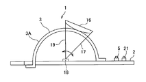
次に、本発明の第6の実施形態について説明する。第6の実施形態は、農作物を拡大視認可能にしたものである。図9は、本発明の第6の実施形態に係る農作物の展示装置の断面図である。
次に、本発明の第6の実施形態について説明する。第6の実施形態は、農作物を拡大視認可能にしたものである。図9は、本発明の第6の実施形態に係る農作物の展示装置の断面図である。
図9に示すように、窓部3の外側の支持台2上に、窓部3の収納部3Aの外周面に接するように配置される拡大視手段である凸レンズ16と、レンズ支持部材17と、凸レンズ16及びレンズ支持部材17を揺動させる揺動駆動装置18と、揺動駆動装置18をオン・オフするスイッチ21と、を備える。
それにより、窓部3内の農作物20(例えば、リンゴ)が見えにくい場合、スイッチ21をオン操作して揺動駆動措置18をオンにし、凸レンズ16を適宜位置に揺動させて、凸レンズ16で農作物20を拡大して見えやすくすることができる。
(第7の実施形態)
次に、本発明の第7の実施形態について説明する。第7の実施形態は、収容空間の機密性を維持する構成を有するものである。図10は、本発明の第7の実施形態に係る農作物展示装置の説明図である。
次に、本発明の第7の実施形態について説明する。第7の実施形態は、収容空間の機密性を維持する構成を有するものである。図10は、本発明の第7の実施形態に係る農作物展示装置の説明図である。
図10に示すように、展示装置1における農作物20を載置する空間の気密性を維持するために、支持台2の開口部2aにパッキン19Aを備え、かつ、開口部2aに入り込んでいない窓部3のフランジ部3Bと支持台2の表面1Aとの間にパッキン19Bを備える。
開口部2aと、開口部2aに入り込んでいない窓部3のフランジ部3Bと支持台2の表面1Aとの間とから、農作物20を載置する空間と外部が連通すると、空間内の温度・湿度を適切に管理することができないので、農作物の鮮度維持に不利である。そこで、上記のようなパッキン19A、19Bを備えることにより、農作物20を載置する空間の気密性を高め、温度・湿度を維持することができる。なお、農作物20を載置する空間の温度や湿度を調整する温度(湿度または温湿度)調整装置を配置して、温度を一定に保ち、及び/または乾燥を防ぎ、農作物の鮮度を維持できるようにしてもよい。
(販売機の構成例)
次に、図1~図10に示した農作物の展示装置の何れかを用いた販売機の構成例について説明する。図11は、本発明の農作物の展示装置を適用した販売機の概略説明図であり、(A)は正面図、(B)は左側面図である。
次に、図1~図10に示した農作物の展示装置の何れかを用いた販売機の構成例について説明する。図11は、本発明の農作物の展示装置を適用した販売機の概略説明図であり、(A)は正面図、(B)は左側面図である。
図11に示すように、4個の展示装置を並べて販売機とした例である。各展示装置は、支持台2の裏面側にボックス22を備えている。このボックス22は、販売機の形態に応じて高さ変更可能であり、また、支持台2と一体形成してもよい。また、展示装置1の1~2個は、支持台2やボックス22をスケルトンにして、支持台2の裏面側が視認できるようにしてもよい。
それにより、農作物をデザイン性よく展示して、販売することができる。
また、窓部3の回転をロックするロック部、ロックを解除する解除部を設けてもよい。それにより、セキュリティ性の高い販売機が実現できる。
なお、前述した実施例は本発明の代表的な形態を示したに過ぎず、本発明は、実施例に限定されるものではない。即ち、本発明の骨子を逸脱しない範囲で種々変形して実施することができる。
また、収容空間の温度を調整する温度調整装置を備えてもよい。それにより、農作物の鮮度を長く維持することができる。
また、支持台2はどんな形でもよいが、円形とすることがデザイン上好ましい。
また、支持台2を回転させる支持台回転装置を備えてもよい。それにより、利用者該導することなく、農作物を全方向から確認できる。
また、農作物の下方にその底側を視認するための反射鏡を支持台2の上などに設けてもよい。この場合、反射鏡を利用者が視認できるよう、支持台2は透明な部材で構成することが好ましい。それにより、農作物の底側も視認できる。
1 展示装置
2 支持台(第2の支持台)
2a 開口部(開閉機構の一部)
3 窓部
3A 収納部
3B フランジ部
3C 回転軸(開閉機構の一部)
3-1 第1の窓部
3-2 第2の窓部
4 光源
6 駆動装置
14 第1の支持台
16 凸レンズ
2 支持台(第2の支持台)
2a 開口部(開閉機構の一部)
3 窓部
3A 収納部
3B フランジ部
3C 回転軸(開閉機構の一部)
3-1 第1の窓部
3-2 第2の窓部
4 光源
6 駆動装置
14 第1の支持台
16 凸レンズ
Claims (19)
- 支持台と、当該支持台に支持され、前記支持台との間で農作物を収容する空間を構成する透明の窓部と、前記窓部を開閉する開閉機構と、を備えていることを特徴とする農作物の展示装置。
- 前記窓部は樹脂で構成されることを特徴とする請求項1に記載の農作物の展示装置。
- 前記樹脂は導光性を有することを特徴とする請求項2に記載の農作物の展示装置。
- 前記樹脂はアクリル系樹脂であることを特徴とする請求項2に記載の農作物の展示装置。
- 前記窓部は、ドーム状収納部を備えることを特徴とする請求項1に記載の農作物の展示装置。
- 前記ドーム状収納部は、仮想球面に沿って形成されていることを特徴とする請求項5に記載の農作物の展示装置。
- 前記ドーム状収納部の中央部における厚さに対して、前記支持台に対面する当該ドーム状収納部の外周部における厚さは大きいことを特徴とする請求項5に記載の農作物の展示装置。
- 前記窓部は、前記ドーム状収納部の外周に配置されるフランジ部を備えていることを特徴とする請求項5に記載の農作物の展示装置。
- 前記フランジ部の厚さは前記ドーム状収納部の厚さに対して大きいことを特徴とする請求項8に記載の農作物の展示装置。
- 前記窓部は、前記支持台に対して回転可能であり、
前記窓部の回転軸は、当該窓部における異なる2つの部位を通過しており、
前記異なる2つの部位は、互いに略同じ高さに位置するとともに、対向する位置に配置されていることを特徴とする請求項5に記載の農作物の展示装置。 - 前記窓部は、第1の窓部と第2の窓部とを備え、
前記第2の窓部は、前記第1の窓部に沿って、前記支持台に対して回転可能であり、
前記第2の窓部の回転軸は、当該窓部における異なる2つの部位を通過しており、
前記異なる2つの部位は、互いに略同じ高さに位置するとともに、対向する位置に配置されていることを特徴とする請求項5に記載の農作物の展示装置。 - 前記窓部には、拡大視手段が設けられていることを特徴とする請求項1に記載の農作物の展示装置。
- 前記支持台は、第1の支持台と、前記第1の支持台に対して移動可能に支持された第2の支持台とを備え、
前記第2の支持台は、前記第1の支持台に沿って移動することを特徴とする請求項1に記載の農作物の展示装置。 - 前記窓部は、駆動装置により前記支持台に対して回転し、
前記支持台は、前記窓部の一部が挿入される開口部を備えることを特徴とする請求項10に記載の農作物の展示装置。 - 前記駆動装置は、ギヤドライブ方式またはベルトドライブ方式であることを特徴とする請求項14に記載の農作物の展示装置。
- 前記支持台に設けられる光源を備えることを特徴とする請求項1に記載の農作物の展示装置。
- 前記光源は、有機ELで構成されることを特徴とする請求項13に記載の農作物の展示装置。
- 請求項1から14の何れかに記載の展示装置を備える販売機。
- 請求項10,11,14,15の何れかに記載の展示装置と、前記窓部の回転をロックするロック部と、前記ロック部のロックを解除する解除部と、を備えることを特徴とする販売機。
Priority Applications (1)
| Application Number | Priority Date | Filing Date | Title |
|---|---|---|---|
| PCT/JP2012/073933 WO2014045352A1 (ja) | 2012-09-19 | 2012-09-19 | 農作物の展示装置及びこれを用いた販売機 |
Applications Claiming Priority (1)
| Application Number | Priority Date | Filing Date | Title |
|---|---|---|---|
| PCT/JP2012/073933 WO2014045352A1 (ja) | 2012-09-19 | 2012-09-19 | 農作物の展示装置及びこれを用いた販売機 |
Publications (1)
| Publication Number | Publication Date |
|---|---|
| WO2014045352A1 true WO2014045352A1 (ja) | 2014-03-27 |
Family
ID=50340711
Family Applications (1)
| Application Number | Title | Priority Date | Filing Date |
|---|---|---|---|
| PCT/JP2012/073933 Ceased WO2014045352A1 (ja) | 2012-09-19 | 2012-09-19 | 農作物の展示装置及びこれを用いた販売機 |
Country Status (1)
| Country | Link |
|---|---|
| WO (1) | WO2014045352A1 (ja) |
Citations (4)
| Publication number | Priority date | Publication date | Assignee | Title |
|---|---|---|---|---|
| JPS61190268U (ja) * | 1985-05-20 | 1986-11-27 | ||
| JPH01129808A (ja) * | 1987-10-31 | 1989-05-23 | Horst Muhlack | 陳列ケース |
| JPH01244718A (ja) * | 1988-03-28 | 1989-09-29 | Sanyo Electric Co Ltd | セパレート型の冷却ショーケース |
| JPH06195558A (ja) * | 1992-09-07 | 1994-07-15 | Sigma- Denki Kogyo Kk | 農産物自動販売機 |
-
2012
- 2012-09-19 WO PCT/JP2012/073933 patent/WO2014045352A1/ja not_active Ceased
Patent Citations (4)
| Publication number | Priority date | Publication date | Assignee | Title |
|---|---|---|---|---|
| JPS61190268U (ja) * | 1985-05-20 | 1986-11-27 | ||
| JPH01129808A (ja) * | 1987-10-31 | 1989-05-23 | Horst Muhlack | 陳列ケース |
| JPH01244718A (ja) * | 1988-03-28 | 1989-09-29 | Sanyo Electric Co Ltd | セパレート型の冷却ショーケース |
| JPH06195558A (ja) * | 1992-09-07 | 1994-07-15 | Sigma- Denki Kogyo Kk | 農産物自動販売機 |
Similar Documents
| Publication | Publication Date | Title |
|---|---|---|
| US8702267B2 (en) | Flashlight with magnets | |
| JP6714205B1 (ja) | 装飾品の陳列棚 | |
| JP2011221214A5 (ja) | ||
| JP5948155B2 (ja) | 回転式役物装置 | |
| JP5256396B2 (ja) | 弾球遊技機 | |
| US20130134056A1 (en) | Light Activated Try-Me Packaging | |
| JP5313734B2 (ja) | 遊技機用可動演出装置及びそれを備えた遊技機 | |
| JP6911477B2 (ja) | 演出操作スイッチ及び遊技機 | |
| JP5611899B2 (ja) | 遊技機 | |
| JP2020178636A (ja) | ハオルシア観賞用のケース及び観賞体 | |
| JP2015058039A (ja) | 遊技機 | |
| JP5090550B2 (ja) | 遊技機 | |
| JP6782489B2 (ja) | 遊技機 | |
| JP5923650B1 (ja) | ベルトパーティションスタンド及びベルトパーティション装置 | |
| JP5747273B2 (ja) | 遊技機 | |
| JP5963911B2 (ja) | 弾球遊技機 | |
| JP5748810B2 (ja) | 弾球遊技機 | |
| JP6404802B2 (ja) | 遊技機 | |
| JP2011181476A (ja) | デイスプレイ照明装置 | |
| JP2017086681A (ja) | 遊技機 | |
| JP2018049772A (ja) | 展示用照明装置及びショーケース | |
| JPWO2016051507A1 (ja) | 表示装置 | |
| JP5927467B2 (ja) | 遊技機 | |
| JP6879024B2 (ja) | 電飾ユニット及び遊技機 | |
| JP5927466B2 (ja) | 遊技機 |
Legal Events
| Date | Code | Title | Description |
|---|---|---|---|
| 121 | Ep: the epo has been informed by wipo that ep was designated in this application |
Ref document number: 12885127 Country of ref document: EP Kind code of ref document: A1 |
|
| NENP | Non-entry into the national phase |
Ref country code: DE |
|
| 122 | Ep: pct application non-entry in european phase |
Ref document number: 12885127 Country of ref document: EP Kind code of ref document: A1 |
|
| NENP | Non-entry into the national phase |
Ref country code: JP |