WO2014045331A1 - 穿刺具及び穿刺具組立体 - Google Patents
穿刺具及び穿刺具組立体 Download PDFInfo
- Publication number
- WO2014045331A1 WO2014045331A1 PCT/JP2012/073774 JP2012073774W WO2014045331A1 WO 2014045331 A1 WO2014045331 A1 WO 2014045331A1 JP 2012073774 W JP2012073774 W JP 2012073774W WO 2014045331 A1 WO2014045331 A1 WO 2014045331A1
- Authority
- WO
- WIPO (PCT)
- Prior art keywords
- puncture
- point
- marker
- puncture device
- outer needle
- Prior art date
- Legal status (The legal status is an assumption and is not a legal conclusion. Google has not performed a legal analysis and makes no representation as to the accuracy of the status listed.)
- Ceased
Links
Images






Classifications
-
- A—HUMAN NECESSITIES
- A61—MEDICAL OR VETERINARY SCIENCE; HYGIENE
- A61B—DIAGNOSIS; SURGERY; IDENTIFICATION
- A61B17/00—Surgical instruments, devices or methods
- A61B17/34—Trocars; Puncturing needles
- A61B17/3417—Details of tips or shafts, e.g. grooves, expandable, bendable; Multiple coaxial sliding cannulas, e.g. for dilating
- A61B17/3421—Cannulas
-
- A—HUMAN NECESSITIES
- A61—MEDICAL OR VETERINARY SCIENCE; HYGIENE
- A61B—DIAGNOSIS; SURGERY; IDENTIFICATION
- A61B17/00—Surgical instruments, devices or methods
- A61B17/56—Surgical instruments or methods for treatment of bones or joints; Devices specially adapted therefor
- A61B17/58—Surgical instruments or methods for treatment of bones or joints; Devices specially adapted therefor for osteosynthesis, e.g. bone plates, screws or setting implements
- A61B17/68—Internal fixation devices, including fasteners and spinal fixators, even if a part thereof projects from the skin
- A61B17/70—Spinal positioners or stabilisers, e.g. stabilisers comprising fluid filler in an implant
- A61B17/7062—Devices acting on, attached to, or simulating the effect of, vertebral processes, vertebral facets or ribs ; Tools for such devices
- A61B17/7065—Devices with changeable shape, e.g. collapsible or having retractable arms to aid implantation; Tools therefor
-
- A—HUMAN NECESSITIES
- A61—MEDICAL OR VETERINARY SCIENCE; HYGIENE
- A61B—DIAGNOSIS; SURGERY; IDENTIFICATION
- A61B17/00—Surgical instruments, devices or methods
- A61B17/34—Trocars; Puncturing needles
- A61B17/3468—Trocars; Puncturing needles for implanting or removing devices, e.g. prostheses, implants, seeds, wires
-
- A—HUMAN NECESSITIES
- A61—MEDICAL OR VETERINARY SCIENCE; HYGIENE
- A61B—DIAGNOSIS; SURGERY; IDENTIFICATION
- A61B17/00—Surgical instruments, devices or methods
- A61B17/28—Surgical forceps
- A61B17/29—Forceps for use in minimally invasive surgery
- A61B2017/2901—Details of shaft
- A61B2017/2904—Details of shaft curved, but rigid
-
- A—HUMAN NECESSITIES
- A61—MEDICAL OR VETERINARY SCIENCE; HYGIENE
- A61B—DIAGNOSIS; SURGERY; IDENTIFICATION
- A61B90/00—Instruments, implements or accessories specially adapted for surgery or diagnosis and not covered by any of the groups A61B1/00 - A61B50/00, e.g. for luxation treatment or for protecting wound edges
- A61B90/39—Markers, e.g. radio-opaque or breast lesions markers
- A61B2090/3966—Radiopaque markers visible in an X-ray image
Definitions
- the present invention relates to a puncture device and a puncture device assembly for puncturing a living body with a puncture portion formed in a curved shape.
- the nerve passes through the spinal canal extending along the spinal column, and when the spinal canal becomes narrow, spinal canal stenosis occurs, in which the nerve is compressed.
- spinal canal stenosis for example, pharmacotherapy, exercise therapy, and orthodontic treatment with a corset are performed.
- surgical treatment is performed by incising the patient's back.
- a procedure for example, PLF, PLIF
- fixing the spinous processes of the vertebrae having spinal canal stenosis with a dedicated fixing tool is performed.
- a puncture device disclosed in FIG. 136 of US Pat. No. 8092459 has a puncture portion formed in a curved shape, and includes a spacer on the proximal end side of the puncture portion.
- the spacer is inserted into the body along with puncturing by the puncturing unit and is placed between the spinous processes.
- a balloon may be used as a spacer placed between the spinous processes. After the balloon is inserted between the spinous processes in a contracted state, the balloon is expanded and cured by being supplied with the filler, and is placed.
- the spacer (balloon) is placed in a desired posture between the spinous processes, so that the upper and lower spinous processes can be favorably supported.
- the puncture state (position, posture, etc.) of the puncture portion inserted into the living body is determined in real time in order to accurately place the spacer between the spinous processes. Have confirmed. That is, during the procedure, X-ray imaging is performed to irradiate X-rays toward the patient's back or side and acquire an X-ray image of the spinal column.
- the present invention has been made to solve the above-described problem, and can puncture a puncture state of a puncture portion formed in a curved shape easily and accurately under radiography, for example, puncture
- An object of the present invention is to provide a puncture device and a puncture device assembly that can perform good treatment by arranging spacers efficiently and accurately when a spacer is disposed between spinous processes using a device.
- the present invention provides a puncture device having a puncture portion to be punctured by a living body, and the puncture portion is connected to a distal end side insertion end portion and the insertion end portion and is curved.
- a puncture unit main body including an extending portion having a shape; a marker having radiographic properties different from that of the puncture unit main body; a first point located at or near the insertion end; and the first A point that forms a vertex of an isosceles triangle that has a second point located on the extension part that is separated from the point by a predetermined distance, and a connection line between the first point and the second point.
- the marker is located at two locations of the first point and the second point, one location of the third point, or the first point. It is characterized by being provided at three points 1 to 3.
- the puncture unit since the puncture unit includes a marker having radiographic properties different from that of the puncture unit main body, the marker is identifiable in the X-ray image, so that the puncture state of the puncture unit formed in a curved shape ( Position, posture, etc.) can be easily determined based on the marker. For example, when the markers are provided at the first to third points, the puncture state can be easily and accurately determined based on the contrast position relationship between the three markers of the X-ray image. As a result, since the puncture part can be punctured normally, when spacers are disposed between the spinous processes, the spacers can be disposed efficiently and accurately to perform good treatment.
- the puncture portion can be configured as a multiple structure including an inner needle and an outer needle that slidably accommodates the inner needle along the axial direction of the puncture portion main body.
- the puncturing portion of the multiple structure including the inner needle and the outer needle the inner needle and the outer needle are overlapped to puncture the living body integrally, and then only the inner needle is pulled out, and the spacer passes through the outer needle. Can be easily performed.
- the marker provided at the first and second points is disposed on the inner needle, and the marker provided at the third point is disposed on the outer needle.
- the markers provided at the first to third points are contrasted in the X-ray image, so that the puncture state of the puncture portion is changed. It can be easily discriminated. Even if the inner needle is removed from the outer needle, it is possible to recognize the positional relationship between the marker provided on the outer needle and the inserted spacer, so that the spacer is accurately arranged at a desired position. be able to.
- the marker provided at the first and second points may be provided on the outer needle, and the marker provided at the third point may be provided on the inner needle.
- the puncture state of the puncture portion can be easily discriminated.
- the outer needle can accommodate a spacer placed in the living body instead of the inner needle, and the first point and the second point are the spacers in a state accommodated in the outer needle. It is good to set to each distance with respect to each edge part.
- the first point and the second point are set at the same distance with respect to the respective end portions of the spacer accommodated in the outer needle.
- the spacer can be easily guided to a position corresponding to the second point. Then, when the guided spacer is exposed from the outer needle, it is positioned with higher accuracy at a desired position in the living body.
- the marker provided at the first point and the marker provided at the second point may be arranged at different positions with respect to a plane including the axis of the puncture unit body.
- the present invention provides a puncture unit main body including a piercing end portion on the distal end side, an extending portion that continues to the piercing end portion and exhibits a curved shape, and the puncture unit main body.
- a puncture device assembly that includes a puncture device that includes a puncture portion that is punctured into a living body, and a spacer that is placed at a predetermined position in the living body via the puncture device.
- the puncture portion is configured as a multiple structure including an inner needle and an outer needle that slidably accommodates the inner needle along the axial direction of the puncture portion main body, and the spacer includes the inner needle Instead of the first needle located at or near the insertion end, and on the extended part spaced from the first point by a predetermined distance.
- markers having radiographic properties different from those of the puncture unit main body are provided at both ends of the spacer, and the first point and the second point are equal to the respective ends of the spacer. It is good to set to distance.
- the first point and the second point are set at an equal distance from the markers provided at both ends of the spacer, and thus correspond to the first point and the second point under radiography.
- the spacer can be easily guided to the position. When the guided spacer is exposed from the outer needle, it is more accurately positioned at a desired position in the living body.
- the spacer may be an expansion body that can be expanded while being exposed from the outer needle.
- the expansion body is expanded and stably placed in accordance with the shape of the arrangement place in the living body.
- the puncture device assembly is used for the treatment of spinal canal stenosis, the puncture portion is punctured between the spinous processes in the living body, the spacer is exposed from the outer needle and is detached from the puncture portion. It is good to be placed between the spinous processes.
- the puncture state of the puncture portion formed in a curved shape can be easily and accurately determined under radiography, for example, between spinous processes using a puncture tool.
- the spacer can be arranged efficiently and accurately to give a good treatment.
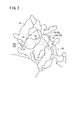
- FIG. 5A is a partial plan view showing a part of the spinal column through which the puncture device of FIG. 1 is punctured
- FIG. 3B is a partial side view showing a part of the spine of FIG. 3A
- FIG. 5A is an arrow figure seen from the arrow IIIC direction.
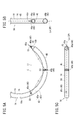
- FIG. 5A is a front view showing the puncture section of FIG. 1, FIG.
- FIG. 5B is a side view showing the puncture section of FIG. 1
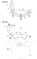
- FIG. 5C is a plan view showing the puncture section of FIG. 6A is a front view showing a state in which a balloon is inserted into the outer needle in FIG. 5A
- FIG. 6B is a front view in which the balloon is exposed and expanded from the outer needle in FIG. 6A
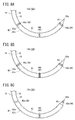
- FIG. 7A is a schematic explanatory diagram illustrating an example of a planar X-ray image acquired in an X-ray imaging during a procedure
- FIG. 7B illustrates an example of a side X-ray image acquired in an X-ray imaging during a procedure. It is a schematic explanatory drawing.
- FIG. 7A is a schematic explanatory diagram illustrating an example of a planar X-ray image acquired in an X-ray imaging during a procedure
- FIG. 7B illustrates an example of a side X-ray image acquired in an X-ray imaging during a procedure. It is a schematic explan
- FIG. 8A is a partial front view showing a puncture part of a puncture device according to a first modification
- FIG. 8B is a partial front view showing a puncture part of a puncture tool according to a second modification
- FIG. It is a partial front view which shows the puncture part of the puncture device which concerns on a 3rd modification
- FIG. 9A is a partial front view showing a puncture portion of the puncture device according to the second embodiment
- FIG. 9B is an explanatory view showing an example of a planar X-ray image when the puncture device of FIG. 9A is used
- FIG. 9C is an explanatory diagram illustrating an example of a side X-ray image when the puncture device of FIG. 9A is used.
- FIG. 9A is a partial front view showing a puncture part of a puncture device according to a first modification
- FIG. 8B is a partial front view showing a puncture part of a puncture tool according to a second modification
- FIG. 10A is a partial front view showing a puncture portion of the puncture device according to the third embodiment
- FIG. 10B is an explanatory view showing an example of a planar X-ray image when the puncture device of FIG. 10A is used
- FIG. 10C is an explanatory diagram illustrating an example of a side X-ray image when the puncture device of FIG. 10A is used.
- the puncture device assembly 10 is a treatment device for performing a minimally invasive procedure (a procedure that does not perform an incision) in the treatment of spinal stenosis.
- the puncture device assembly 10 includes a puncture device 12 having a double tube puncture portion 14 composed of a curved inner needle 16 and an outer needle 18, and punctured into a living body.
- the balloon 20 spacer: expansion body which can be detained via the puncture device 12 is provided.
- the inner needle 16 and the outer needle 18 are integrally punctured between the spinous processes 52 and 52 of the spinal column 50 which is an indwelling place from the back of the patient.
- the inner needle 16 is withdrawn from the outer needle 18, and the balloon 20 is inserted between the spinous processes 52, 52 through the outer needle 18 to expand and harden the balloon 20. Thereby, the hardened balloon 20 is placed between the spinous processes 52.
- FIG. 3A is a partial plan view showing a part of the spinal column 50 into which the puncture instrument 12 of FIG. 1 is punctured
- FIG. 3B is a partial side view of the spinal column 50 of FIG. 3A
- FIG. It is an arrow figure seen from arrow IIIC direction.
- one vertebra 54 includes a vertebra 56 that is closer to the front of the human body, a pair of left and right pedicles 58 that protrude rearward from the posterior side of the vertebra 56, and a pedicle.
- a pair of protrusions 64 (including upper joint protrusions, papillary protrusions, and lateral protrusions) protruding upward.
- a substantially triangular vertebra 66 is formed between the vertebral body 56, the pair of pedicles 58, and the lamina 60 in a cross-sectional view of the spinal column 50 (see FIG. 3C).
- the nerve is inserted through.
- the spinal canal 68 is formed along the extending direction of the spinal column 50 by connecting a plurality of vertebral holes 66 (vertebrae 54).
- Two vertically adjacent vertebrae 54 sandwich an intervertebral disc 70 between the vertebral bodies 56, and a pair of protrusions 64 of the lower vertebra 54B are located on the upper side.
- the vertebrae 54A are connected in a state of entering between the lower joint processes 62.
- an interspinous ligament (not shown) is interposed between the spinous process 52 of the upper vertebra 54A and the spinous process 52 of the lower vertebra 54B, and connects the two spinous processes 52 and 52 to each other.
- a spinal canal 68 composed of an elongated space formed by connecting vertebral holes 66 existing between an anterior portion and a posterior portion of the spinal column 50, generally called the spine, is composed of an intervertebral disc 70, a vertebral body 56, It is narrowed due to degeneration of the facet joint, pedicle 58 and vertebral disc 60, thickening of the yellow ligament, etc., and the nerve passing through the spinal canal 68 is compressed and symptoms such as intermittent claudication appear .
- the balloon 20 is disposed so that the spinous process 52 of the upper vertebra 54A and the spinous process 52 of the lower vertebra 54B are spaced apart from each other, and the stenosis of the spinal canal 68 is released. This reduces stenosis of the spinal canal 68 and relieves nerve compression.
- the balloon 20 disposed between the spinous processes 52 by the puncture device 12 includes a pair of left and right ball portions 22 and 22 and a connecting portion 24 that connects the pair of ball portions 22 and 22. And is placed in the root portion (the lamina 60 side) between the spinous processes 52, 52.
- the pair of ball portions 22, 22 sandwich the side surface of the spinous process 52 extending vertically, and the connecting portion 24 is between the spinous process 52 of the upper vertebra 54 ⁇ / b> A and the spinous process 52 of the lower vertebra 54 ⁇ / b> B. Placed in.
- a pair of confirmation markers 26 (tip confirmation marker 26a, proximal confirmation marker 26b) having X-ray contrast properties different from those of the puncture unit 14 are provided at both ends of the balloon 20 in the longitudinal direction.
- the pair of confirmation markers 26 recognizes the position and posture of the balloon 20 under X-ray imaging when the balloon 20 is inserted or placed.
- the balloon 20 is configured as an inserted device in which a hollow tube 28 (see FIG. 6B) is connected to the proximal end confirmation marker 26b, and a filler is supplied into the balloon 20 through the tube 28 after insertion.
- the filler filled in the balloon 20 is preferably a material that cures in a short time near body temperature.
- a two-component mixed cross-linked polymer, a hot melt adhesive, a urethane elastomer, a photocurable resin, a thermoplastic resin examples include acrylic resin and bone cement.
- the proximal end confirmation marker 26b and the tube 28 are provided with a detachment mechanism 30 (see FIG. 6B) so that the tube 28 can be separated from the expanded balloon 20 by a simple operation.
- the detachment mechanism 30 include a structure in which the proximal end confirmation marker 26b and the tube 28 are screwed together.
- the longitudinal axis Lb thereof is in a state of being substantially orthogonal to the axis Ls of the spinal column 50.
- the balloon 20 can support the other spinous process 52 by one spinous process 52, and can maintain the space between the spinous processes 52 and 52 well at a predetermined interval.
- the arrangement state where the balloon 20 is tilted and placed and the longitudinal axis Lb and the axis Ls of the spine 50 are not orthogonal it is difficult to support the spinous processes 52 and 52. For this reason, during the procedure, X-ray imaging of a treatment site for spinal stenosis is performed, and the puncture state of the puncture device 12 and the arrangement state of the balloon 20 are confirmed.
- FIG. 4 is a schematic explanatory view showing the state of the procedure using the puncture device assembly 10 of FIG.
- an operating table 32 for a patient to chew an X-ray source 34 that can move above and to the side of the operating table 32, and an X-ray source 34 that faces the patient.
- An X-ray reader (not shown) that can move with the X-ray source 34 at a position and a display device 36 that displays an X-ray image read by the X-ray reader are provided.
- X-rays are emitted from an X-ray source 34, X-rays transmitted through the patient are read by an X-ray reader, converted into an X-ray image, and displayed on the display device 36. Therefore, the doctor or the like can perform the procedure while checking the X-ray image (moving image) displayed on the display device 36 in real time.
- an X-ray image 100 (planar view of the spinal column 50 as shown in FIG. 3A). Also referred to as a planar X-ray image 102. See also FIG. 7A).
- an X-ray image 100 (also referred to as a side X-ray image 104; see FIG. 7B) is obtained by viewing the spinal column 50 from the side. .
- the side X-ray image 104 is acquired by X-ray irradiation from above, and the plane X-ray image 102 is acquired by X-ray irradiation from the side.
- an X-ray image obtained by cutting the spinal column 50 into a circle (cross-sectional view) as shown in FIG. 3C is obtained by CT scan or the like, and it is difficult to check this X-ray image in real time during the procedure.
- X-rays irradiated during the procedure are irradiated from above (in the direction of arrow X1 in FIG. 1) and from the side (in the direction of arrow X2 in FIG. 1) with respect to the puncture portion 14 formed in a curved shape. Will be.
- the puncture part 14 actually imaged is contrasted in a bar shape in the planar X-ray image 102 and is also contrasted in a bar shape in the side surface X-ray image 104 (see, for example, FIGS. 7A and 7B).
- the puncture device 12 (puncture device assembly 10) according to the first embodiment can accurately determine the puncture state of the puncture device 12 even when the plane X-ray image 102 and the side surface X-ray image 104 are acquired by X-ray imaging. Configured as a simple device. Hereinafter, the puncture device 12 (puncture device assembly 10) will be specifically described.
- the puncture device 12 of the puncture device assembly 10 has the puncture portion 14 as described above, and an operation portion 38 for a doctor to hold is connected to the proximal end side of the puncture portion 14.
- the inner needle 16 of the puncture unit 14 has an arc shape that is entirely curved with a substantially constant curvature.
- the distal end side of the inner needle 16 is formed in an insertion portion 40 having an acute angle that can be easily inserted into a living body, and the most distal end portion is an insertion end portion 40a.
- the body portion of the inner needle 16 is formed in an inner needle side extending portion 42 a that extends to the proximal end side while being curved and connected to the insertion portion 40.
- the inner needle 16 may have a solid or hollow structure.
- An operation portion 38 is connected and fixed to the proximal end portion of the inner needle 16, and an operation force from the operation portion 38 can be directly transmitted to the insertion end portion 40a at the time of puncturing.
- the outer needle 18 is configured as a tubular body, and has an outer needle side extending portion 42b having the same curvature as the inner needle side extending portion 42a, so that the outer needle 18 is formed in an overall curved arc shape.
- an accommodation space 18a for slidably accommodating the inner needle 16 is provided inside the outer needle 18.
- a flange portion 44 that is exposed on the skin of the living body at the time of puncture and has a diameter that is larger in the radial direction than the outer needle side extending portion 42b is provided.
- the flange portion 44 is fixed in contact with the operation portion 38, and the inner needle 16 and the outer needle 18 are integrated. It is possible to operate. Further, the extending length of the outer needle 18 is slightly shorter than that of the inner needle 16, and the insertion portion 40 of the inner needle 16 is just exposed from the distal end opening 18b of the accommodation space 18a in the puncture enabled state.
- the puncture portion 14 constituted by the inner needle 16 and the outer needle 18 is in a puncturable state, and the puncture portion 40 having the insertion end portion 40a, the inner needle side extending portion 42a, and the outer needle side extending portion.
- the puncture part main body 45 is configured to include the extending part 42 on which the existing part 42b overlaps. And it inserts in the living body from the insertion part 40 along a curved shape.
- the puncture portion 14 of the puncture device 12 used for spinal canal stenosis preferably has a rigidity that allows puncture between the spinous processes 52 and 52.
- the constituent materials of the inner needle 16 and the outer needle 18 are not particularly limited.
- a metal material such as stainless steel, aluminum or an aluminum alloy, titanium or a titanium alloy, a hard resin material, or the like. The combination of is mentioned.
- the inner needle 16 and the outer needle 18 may be comprised by the same material, and may be comprised by a mutually different material.
- the puncture unit 14 includes three markers 46 having X-ray contrast properties different from those of the puncture unit main body 45 at predetermined positions.
- the puncture unit 14 according to the first embodiment has a function of reliably determining the puncture state of the puncture device 12 and the arrangement state of the balloon 20 during the procedure based on the arrangement relationship of these three markers 46. Therefore, the configuration of the three markers 46 will be specifically described next.
- FIG. 5A is a front view showing the puncture unit 14 of FIG. 1
- FIG. 5B is a side view showing the puncture unit 14 of FIG. 1
- FIG. 5C is a plan view showing the puncture unit 14 of FIG. 6A is a front view showing a state in which the balloon 20 is inserted into the outer needle 18 in FIG. 5A
- FIG. 6B is a front view in which the balloon 20 is exposed and expanded from the outer needle 18 in FIG. 6A.
- the three markers 46 are referred to as a distal marker 46a, a deep marker 46b, and a proximal marker 46c from the insertion end 40a of the puncture unit 14 toward the proximal end so that the three markers 46 can be individually recognized. .
- the three markers 46 have a contrast property that allows the locations of the markers 46 to be sufficiently identified in the X-ray image 100 acquired by X-ray imaging.
- the three markers 46 may be formed of a material having a radiopaque property higher than that of the puncture unit main body 45.
- the three markers 46 are displayed as black portions including darker shadows with respect to the puncture unit main body 45 that is contrasted with thin shadows, and the positional relationship between the three markers 46 is indicated. It can be easily visually recognized.
- the three markers 46 (particularly, the distal marker 46 a and the proximal marker 46 c) may have different contrast properties and may be set so that they can be individually identified in the X-ray image 100.
- the marker 46 in this specification is used in the sense that the X-ray image 100 has high discrimination. Therefore, the marker 46 (including the confirmation marker 26) or the puncture unit main body 45 contrasted in the X-ray image 100 is not only X-ray opaque that absorbs X-rays but also X-ray transparent that transmits X-rays. It may have a configuration that can be distinguished from the surroundings.
- the three markers 46 are a first point O1 located in the insertion part 40 (near the insertion end part 40a) and a second point located on the extension part 42 that is separated from the first point O1 by a predetermined distance.
- a point O2 and a third point O3 which is a point forming the vertex of an isosceles triangle IT with the connection line C between the first point O1 and the second point O2 as the base and located on the extending portion 42 are set. By doing so, the puncture unit 14 is provided at a predetermined position.
- the tip marker 46a is disposed in the insertion portion 40 (near the insertion end portion 40a) of the inner needle 16 in accordance with the set position of the first point O1, and is exposed from the outer needle 18 in the puncture enabled state.
- the tip marker 46 a is provided so as to partially cover the outer peripheral surface of the insertion portion 40. Specifically, as shown in FIG. 5C, when the virtual surface IP including the axis Ln of the puncture unit main body 45 is set, it is provided on the outer peripheral surface (half circumference) of the portion below the virtual surface IP. .
- the base end marker 46c is disposed on the inner needle side extending portion 42a of the inner needle 16 according to the set position of the second point O2. Therefore, the proximal marker 46c is present in the outer needle 18 in a puncturable state and cannot be confirmed by visual observation, but can be visually recognized by the X-ray image 100 by having a contrast property different from that of the extending portion 42.
- the second point O2 for disposing the proximal marker 46c is preferably set using the balloon 20 accommodated in the accommodation space 18a of the outer needle 18 and the first point O1.
- the setting method of the second point O2 will be specifically described with reference to FIG. 6A.
- the first point O1 is set at the insertion portion 40 of the inner needle 16 in a puncturable state.
- the balloon 20 is inserted into the accommodation space 18 a of the outer needle 18, the tip confirmation marker 26 a is guided near the tip opening 18 b of the outer needle 18, and the balloon 20 moves at that position.
- the distance d1 from the tip confirmation marker 26a to the first point O1 is measured.
- the position of the proximal end confirmation marker 26b with respect to the puncture portion 14 is also determined, so that the end on the extended portion 42 that is the same distance as the distance d1 from the proximal end confirmation marker 26b Is set to point O2. That is, the distance d2 from the proximal end confirmation marker 26b to the second point O2 is set equal to the distance d1 from the distal end confirmation marker 26a to the first point O1.
- the balloon 20 can be easily arranged during the procedure. That is, when the balloon 20 is guided along the curved shape of the outer needle 18, the distal end and proximal end confirmation markers 26a and 26b are approximately at the first point O1 and the second point O2, respectively, under X-ray imaging. When they are inserted so as to be equal, the intermediate portion (connecting portion 24) of the balloon 20 is disposed at a position that substantially coincides with the intermediate portion (third point O3) between the first point O1 and the second point O2.
- the middle part of the balloon 20 can be expanded at a position overlapping with the axis Ls of the spinal column 50, and the connecting part 24 of the balloon 20 can be favorably disposed between the spinous processes 52, 52 (see FIG. 6B). .
- the proximal marker 46c disposed at the second point O2 is partially provided on the outer peripheral surface of the inner needle side extending portion 42a so as to be displaced from the distal marker 46a. That is, as shown in FIG. 5C, the proximal marker 46 c is provided on the outer circumferential surface (half circumference) of the portion above the virtual surface IP when the virtual surface IP including the axis Ln of the puncture unit body 45 is set. ing.
- the deep marker 46b is provided on the outer needle side extending portion 42b at a position corresponding to the setting of the third point O3.
- the third point O3 is set to the vertex of the isosceles triangle IT with the connection C between the first point O1 and the second point O2 as the base, and therefore, the first point O1 and the second point If O2 is determined, it can be easily set.
- the deep marker 46b is disposed on the puncture portion 14 at an intermediate portion between the distal marker 46a and the proximal marker 46c. Further, unlike the distal marker 46a and the proximal marker 46c, the deep marker 46b is annularly provided on the outer peripheral surface of the outer needle side extending portion 42b.
- the three markers 46 arranged on the puncture unit body 45 are all inserted into the living body as the puncture unit body 45 is punctured into the living body. Then, the three markers 46 are imaged on the X-ray image 100 acquired by X-ray imaging.
- the puncture device 12 and the puncture device assembly 10 according to the first embodiment are basically configured as described above. Hereinafter, based on a procedure using the puncture device assembly 10, the operation and effect thereof will be described. Will be described.
- a doctor or the like grasps the operation unit 38 (see FIG. 1) of the puncture device 12, and the puncture is possible (the inner needle 16 is inserted into the outer needle 18 and the insertion unit 40 is The puncture portion 14 in a state exposed from the distal end opening 18b of the outer needle 18 is percutaneously inserted from the patient's back.
- a CT scan or the like is performed to grasp in advance the upper vertebra 54A and the lower vertebra 54B to be treated, and the shape and position of these vertebrae 54 (for example, the spinous process 52 from the skin) The depth to the root part of). Therefore, the puncture location and puncture direction of the puncture unit 14 are set in advance based on the shapes and positions of the upper vertebra 54A and the lower vertebra 54B.
- the puncturing unit 14 When the puncture unit 14 is inserted into the living body by an operation of a doctor or the like, the puncturing unit 14 proceeds in the living body while drawing an arc-shaped trajectory. Then, after passing through the root portion between the spinous processes 52 deeply punctured from the skin, the puncture is further performed to the desired position while facing the skin side. At this time, an X-ray image 100 is acquired under X-ray imaging, and puncture is performed while confirming the puncture state (position and posture) of the puncture unit 14 based on the X-ray image 100.
- FIG. 7A is a schematic explanatory diagram illustrating an example of a planar X-ray image 102 acquired in an X-ray imaging during a procedure
- FIG. 7B illustrates an example of a side X-ray image 104 acquired in an X-ray imaging during a procedure. It is a schematic explanatory drawing which shows.
- the plane X-ray image 102 as shown in FIG. 7A and the side X-ray image 104 as shown in FIG. 7B are arbitrarily acquired by moving the X-ray source 34 and the X-ray reader in accordance with instructions from a doctor or the like. To do.
- FIGS. 7A and 7B are different from actual X-ray images and are illustrated with the hatched portions of the three markers 46 remaining on the puncture portion 14 illustrated in black.
- the spinal column 50 extends vertically, and the spinous processes 52 of the vertebrae 54 aligned vertically are displayed along the axis Ls of the spinal column 50.
- the puncture unit 14 is contrasted in a rod shape so that the axis Ls of the spinal column 50 is orthogonal, and the puncture unit 14 is punctured while the three markers 46 are visually recognized well (see the hatched portion in FIG. 7A).
- the puncture of the puncture unit 14 is such that the deep marker 46b is positioned on the axis Ls of the spinal column 50, the distal marker 46a is positioned to the right of the deep marker 46b, and the proximal marker 46c is at the same interval as the distal marker 46a. The process is performed until it is located to the left of the deep marker 46b.
- the axis Ln of the puncture unit main body 45 is substantially orthogonal to the axis Ls of the spinal column 50.
- the puncture unit 14 is tilted and punctured. it can.
- the spinal column 50 extends in the vertical direction, and the spinous processes 52 of the vertebrae 54 aligned in the vertical direction are displayed in a state of protruding toward the right side on the skin side.
- the puncture part 14 is punctured from the skin side to the root part between the spinous processes 52 and 52, it extends from the right side of the side X-ray image 104 and is contrasted in a rod shape extending between the spinous processes 52 and 52. .
- the puncture unit 14 is punctured while the three markers 46 are satisfactorily viewed in the side X-ray image 104 (see the white and hatched portions in FIG. 7B).
- the deep marker 46b is visually recognized in an annular shape at the root portion between the spinous processes 52. In other words, it is possible to determine that the puncture unit 14 has reached the desired position by visually recognizing the deep marker 46b at the root portion. In the state where the deep marker 46b is located at the root portion, the distal marker 46a and the proximal marker 46c are visually recognized at the same position on the right side of the deep marker 46b (see also FIG. 5B).
- distal marker 46a and the proximal marker 46c are greatly displaced up and down, it can be determined that the puncture part 14 is tilted and punctured, and if the distal marker 46a and the proximal marker 46c are displaced left and right, It can be determined that the puncture direction of the puncture unit 14 is not normal (not punctured along the curved shape).
- the distal marker 46a and the proximal marker 46c are arranged at different positions with reference to the virtual plane IP including the axis Ln of the puncture unit 14, the distal marker 46a and the proximal marker 46c are included in the side X-ray image 104. Are imaged without overlapping each other. Therefore, even if the distal end marker 46a and the proximal end marker 46c are present at the same position on the axis Ln of the puncture unit main body 45 in the side surface X-ray image 104, the doctor or the like can be individually identified.
- the three markers 46 of the puncture unit 14 are contrasted in the plane X-ray image 102 or the side X-ray image 104, so that the puncture state of the puncture unit 14 can be well determined based on the positional relationship. . Therefore, the doctor or the like maintains the orthogonality of the axis Ln of the puncture unit main body 45 with respect to the axis Ls of the spinal column 50, and until the deep marker 46b is positioned on the axis Ls of the spinal column 50 and at the root portion between the spinous processes 52, 52. The puncture portion 14 can be punctured easily.
- the inner needle 16 After puncturing the puncture portion 14 between the spinous processes 52, 52, the inner needle 16 is moved backward with respect to the outer needle 18, and the inner needle 16 is pulled out from the outer needle 18. In this state, since only the outer needle 18 remains in the living body, only the deep marker 46 b of the three markers 46 is imaged on the planar X-ray image 102 or the side X-ray image 104.
- the balloon 20 is inserted into the accommodation space 18a, and the balloon 20 is inserted to the distal end side of the outer needle 18.
- the confirmation marker 26 is imaged by X-ray imaging. Therefore, when the intermediate portion between the distal end confirmation marker 26a and the proximal end confirmation marker 26b is guided so as to overlap the deep portion marker 46b, the balloons 20 are present evenly on the left and right with respect to the deep portion marker 46b (spinous process 52). .
- the outer needle 18 is moved backward until the balloon 20 is entirely exposed.
- the balloon 20 remains in the puncture site of the puncture unit 14, and the balloon 20 can be easily expanded by supplying the filler to the balloon 20 via the tube 28 (see FIG. 6B).
- the tube 28 is detached from the balloon 20 by the detachment mechanism 30, and the outer needle 18 and the tube 28 are removed from the living body. As a result, only the balloon 20 is placed between the spinous processes 52 and 52.
- the balloon 20 is reliably arranged such that the connecting portion 24 coincides with the axis Ls of the spine 50 and the longitudinal axis Lb is substantially orthogonal to the axis Ls of the spine 50.
- the balloon 20 can favorably support the spinous processes 52 of the upper vertebra 54A and the spinous processes 52 of the lower vertebra 54B at a predetermined interval.
- the puncture device 12 (puncture device assembly 10) is not limited to the above-described configuration, and can of course have various configurations.
- some modifications of the puncture device 12 (puncture device assembly 10) provided with the three markers 46 will be described with some examples.
- the same components as those of the puncture device 12 and the puncture device assembly 10 according to the first embodiment or configurations having the same functions are denoted by the same reference numerals, and detailed description thereof is omitted.
- the distal marker 46a and the proximal marker 46c are provided on the outer needle side extending portion 42b, and the deep marker 46b is extended on the inner needle side. It is the structure provided in the existing part 42a. Therefore, the members disposed with the distal marker 46a, the deep marker 46b, and the proximal marker 46c according to the first embodiment are reversed. Even in this configuration, when the puncture device 12a is punctured, the three markers 46 are imaged on the plane X-ray image 102 and the side X-ray image 104, so that the puncture of the puncture unit 14 can be performed normally. Can do. Further, when guiding the balloon 20, both the distal end marker 46 a and the proximal end marker 46 c of the outer needle 18 and the confirmation marker 26 of the balloon 20 are imaged together. Therefore, the balloon 20 can be guided appropriately.
- the puncture device 12b (puncture device assembly 10b) according to the second modification shown in FIG. 8B has all the three markers 46 (the distal marker 46a, the deep marker 46b, and the proximal marker 46c) on the outer needle side extending portion 42b. It has a configuration with. Even if comprised in this way, the puncture tool 12b can be punctured satisfactorily and the balloon 20 can be inserted with high accuracy.
- the puncture device 12c (puncture device assembly 10c) according to the third modification shown in FIG. 8C has all the three markers 46 (the distal marker 46a, the deep marker 46b, and the proximal marker 46c) on the inner needle side extending portion 42a. It has a configuration with. Even if comprised in this way, the puncture tool 12c can be punctured satisfactorily.
- the members (inner needle 16 and outer needle 18) on which the marker 46 is to be disposed are not particularly limited and may be freely selected.
- the inner needle 16 and the outer needle 18 are made of the same X-ray contrast or X-ray transmissive material as the spine 50. Also good.
- the X-ray image 100 only the three markers 46 of the puncture unit 14 are visually recognized without the puncture unit main body 45 being visually recognized. The puncture state of the puncture unit 14 can be easily determined based on the contrast position.
- the puncture unit 14 includes the three markers 46 having radiographic properties different from those of the puncture unit main body 45, so that three The marker 46 is identifiable on the X-ray image 100.
- the puncture state (position or posture) of the puncture unit 14 formed in a curved shape can be easily determined based on the contrast position relationship of the three markers 46.
- the puncture unit 14 can be punctured to a desired position with a desired posture with high accuracy, so that the balloon 20 can be efficiently and accurately disposed between the spinous processes 52 and 52.
- the treatment can be performed well.
- first point O1 and the second point O2 are set at equal distances from the respective ends of the balloon 20 accommodated in the outer needle 18, so that the first point O1 and the second point O2 are set to be equal to each other.
- the balloon 20 can be easily guided to a position corresponding to the point O2.
- the central portion of the longitudinal axis Lb overlaps with the spinous processes 52, and the balloon 20 is positioned between the spinous processes 52 with high accuracy.
- the balloon 20 expands according to the shape of the spinous process 52 and is stably placed between the spinous processes 52, 52, the upper and lower spinous processes 52 can be maintained at a predetermined interval.
- FIG. 9A is a partial front view showing the puncture portion 14 of the puncture device 13A according to the second embodiment
- FIG. 9B is an explanation showing an example of the planar X-ray image 102 when the puncture device 13A of FIG. 9A is used
- FIG. 9C is an explanatory diagram showing an example of a side X-ray image 104 when the puncture device 13A of FIG. 9A is used.
- a puncture device 13A (puncture device assembly 11A) according to the second embodiment includes a puncture portion 14 composed of an inner needle 16 and an outer needle 18 as in the first embodiment. It has an X-ray contrast property different from that of the surrounding biological tissue, and the markers 46 are provided only at two places on the puncture unit main body 45. Specifically, a tip marker 46a is provided corresponding to the first point O1 set at the tip of the outer needle side extending portion 42b, and the outer needle side extending at a predetermined interval from the first point O1. A proximal marker 46c is provided corresponding to the second point O2 set on the existing portion 42b.
- the puncture device 13A includes the deepest portion 48 (third point O3: isosceles triangle IT having the connection C between the first point O1 and the second point O2 as a base when the puncture unit 14 is punctured into a living body.
- the marker 46 is not disposed at the apex.
- the setting method of the 1st point O1 and the 2nd point O2 can take the same method as the puncture tool 12 which concerns on 1st Embodiment.
- the distal end marker 46a and the proximal end marker 46c are formed at positions shifted from each other when the virtual plane IP including the axis Ln of the puncture unit body 45 is set.
- the puncture state of the puncture portion 14 can be well determined only by providing the distal end marker 46a and the proximal end marker 46c. That is, since the X-ray contrast property of the puncture unit main body 45 is different from that of the spinal column 50 and the surrounding biological tissue, the puncture unit main body 45 is contrasted in a bar shape in the X-ray image 100. Therefore, the puncture state (position, posture, etc.) of the puncture unit 14 with respect to the spinal column 50 can be determined by the puncture unit main body 45 contrasted in the X-ray image 100.
- the posture of the puncture unit 14 is controlled so as to be orthogonal to the axis Ls of the spinal column 50. Then, the puncture is continued while confirming the contrast positions of the distal marker 46a and the proximal marker 46c, and the intermediate portion of the two markers 46 is punctured to a position that coincides with the axis Ls of the spinal column 50.
- the part 48 coincides with the axis Ls of the spinal column 50.
- the posture of the puncture unit 14 is controlled so that the deepest part 48 of the puncture unit 14 passes through the root portion between the spinous processes 52 and 52. Then, while confirming the contrast positions of the distal marker 46a and the proximal marker 46c, puncture is performed until the two markers 46 overlap each other. Thereby, the puncture state similar to the side X-ray image 104 shown in FIG. 7B can be formed.
- the puncture state of the puncture unit 14 can be determined based on the relationship between the contrast of the puncture unit main body 45 and the contrast positions of the distal marker 46a and the proximal marker 46c. Therefore, the puncture device 13A (puncture device assembly 11A) according to the second embodiment can achieve the same effects as those of the first embodiment, and the marker 46 can be easily formed.
- the two markers 46 are provided on the outer needle 18, but the present invention is not limited to this, and the two markers 46 may be provided on the inner needle 16. May be provided separately.
- FIG. 10A is a partial front view showing the puncture unit 14 of the puncture device 13B according to the third embodiment
- FIG. 10B is an explanation showing an example of the planar X-ray image 102 when the puncture device 13B of FIG. 10A is used
- FIG. 10C is an explanatory diagram illustrating an example of a side X-ray image 104 when the puncture device 13B of FIG. 10A is used.
- the puncture device 13B (puncture device assembly 11B) according to the third embodiment includes the puncture portion 14 including the inner needle 16 and the outer needle 18 as in the first and second embodiments, but the puncture portion main body 45 is a spinal column. 50 and an X-ray contrast property different from the surrounding biological tissue, and the marker 46 is provided only at one position of the puncture unit main body 45.
- the setting method of the 1st point O1 and the 2nd point O2 can take the same method as the puncture tool 12 which concerns on 1st Embodiment.
- the puncture unit 14 is imaged in a rod shape on the X-ray image 100 as in the puncture device 12 according to the first embodiment. 14 position and inclination can be discriminated.
- the posture of the puncture unit 14 is controlled so as to be orthogonal to the axis Ls of the spinal column 50. Then, the deep marker 46 b is punctured to a position that coincides with the axis Ls of the spinal column 50. As described above, also in the puncture device 13B, the puncture state of the puncture unit 14 can be determined similarly to the planar X-ray image 102 illustrated in FIG. 7A.
- the posture of the puncture unit 14 is controlled so that the deep marker 46b passes through the root portion between the spinous processes 52. If the deep marker 46b is positioned exactly at the root portion between the spinous processes 52, the puncture depth and puncture amount of the puncture unit 14 can be grasped, and the inclination thereof can be visually recognized based on the contrast of the puncture unit 14. . Thereby, the puncture state of the puncture part 14 can be discriminate
- the puncture state of the puncture unit 14 can be determined based on the relationship between the contrast of the puncture unit main body 45 and the contrast position of the deep marker 46b. Therefore, the puncture device 13B (puncture device assembly 11B) according to the third embodiment can obtain the same effects as those of the first and second embodiments, and the marker 46 can be easily formed. .
- the deep marker 46b may be provided on the inner needle 16.
- the tip marker 46a (first point O1) is not limited to the arrangement in the vicinity of the insertion end 40a, and may be provided in the insertion end 40a itself.
- the puncture devices 12, 12a to 12c, 13A and 13B and the puncture device assemblies 10, 10a to 10c, 11A and 11B according to the present invention are not only applied to the treatment of spinal canal stenosis.
- the curved puncture portion 14 can be suitably used when puncturing a living body.
- the puncture part 14 punctured by the living body is not limited to a multiple structure, and may be a structure that is punctured alone.
- a puncture device having only a needle function without inserting an indwelling object such as the balloon 20 may be used.
Landscapes
- Health & Medical Sciences (AREA)
- Life Sciences & Earth Sciences (AREA)
- Orthopedic Medicine & Surgery (AREA)
- Surgery (AREA)
- Medical Informatics (AREA)
- Engineering & Computer Science (AREA)
- Biomedical Technology (AREA)
- Heart & Thoracic Surgery (AREA)
- Nuclear Medicine, Radiotherapy & Molecular Imaging (AREA)
- Molecular Biology (AREA)
- Animal Behavior & Ethology (AREA)
- General Health & Medical Sciences (AREA)
- Public Health (AREA)
- Veterinary Medicine (AREA)
- Neurology (AREA)
- Pathology (AREA)
- Surgical Instruments (AREA)
Description
本発明は、湾曲形状に形成された穿刺部を生体に穿刺するための穿刺具及び穿刺具組立体に関する。
脊柱に沿って延在する脊柱管には神経が通っており、この脊柱管が狭くなると、神経が圧迫される脊柱管狭窄症が生じる。脊柱管狭窄症に対しては、例えば、薬物療法や運動療法、コルセットを装着する装具療法等が行われるが、重度の場合は、患者の背中を切開する外科的治療が施される。この治療では、切開後に、脊柱管狭窄症を生じている椎骨の棘突起同士を専用の固定具で固定する手技(例えば、PLF、PLIF)等が行われる。
しかしながら、上記のような外科的治療は、患者への侵襲度が高い。このため、近年では、穿刺具を背中から経皮的に穿刺し、棘突起間にスペーサを留置する手技が提案されている(例えば、米国特許第8092459号明細書参照)。
米国特許第8092459号明細書の図136等に開示されている穿刺具は、湾曲形状に形成された穿刺部を有し、この穿刺部の基端側にスペーサを備える。スペーサは、穿刺部による穿刺にともなって体内に挿入されて棘突起間に留置される。また、同明細書の図40~図46等に示されるように、棘突起間に留置するスペーサとしてバルーンを用いてもよい。バルーンは、棘突起間に収縮状態で挿入された後、充填材が内部に供給されることで拡張及び硬化して留置される。このように、スペーサ(バルーン)が棘突起間に所望の姿勢で留置されることで、上下の棘突起同士を良好に支持することができる。
また、上記のような穿刺具を用いて手技を行う場合には、スペーサを棘突起間に精度よく配置するために、生体内に挿入された穿刺部の穿刺状態(位置や姿勢等)をリアルタイムに確認している。すなわち、手技中に、患者の背中又は側面に向けてX線を照射し、脊柱のX線画像を取得するX線撮影を行っている。
しかしながら、湾曲形状に形成された穿刺具を用いる場合は、上記のようにX線撮影を行ったとしても、X線画像に穿刺部が棒状に造影されてしまい、その穿刺状態について充分に判別することができない。このため、穿刺部が棘突起間の所望位置に穿刺されない、又は脊柱に対して斜めに穿刺される等の穿刺不良が生じ、穿刺後に留置するスペーサも斜めに配置される等の不都合が発生してしまう。
本発明は、上記の課題を解決するためになされたものであって、湾曲形状に形成された穿刺部の穿刺状態を、放射線撮影下において、容易且つ精度良く判別することができ、例えば、穿刺具を用いて棘突起間にスペーサを配置する場合に、スペーサを効率的且つ正確に配置させて良好な治療を施すことができる穿刺具及び穿刺具組立体を提供することを目的とする。
上記の課題を解決するために、本発明は、生体に穿刺される穿刺部を有する穿刺具であって、前記穿刺部は、先端側の刺入端部、及び前記刺入端部に連なり湾曲形状を呈する延在部を含む穿刺部本体と、前記穿刺部本体と異なる放射線造影性を有するマーカとを備え、前記刺入端部又はその近傍に位置する第1の点と、前記第1の点から所定の間隔離れた前記延在部上に位置する第2の点と、前記第1の点と前記第2の点の結線を底辺とした二等辺三角形の頂点をなす点であって前記延在部上に位置する第3の点とを設定した場合に、前記マーカは、前記第1の点と前記第2の点の2箇所、若しくは前記第3の点の1箇所、又は前記第1~3の点の3箇所に設けられることを特徴とする。
上記によれば、穿刺部が穿刺部本体と異なる放射線造影性を有するマーカを備えることで、X線画像にマーカが識別可能に造影されるため、湾曲形状に形成された穿刺部の穿刺状態(位置や姿勢等)をマーカに基づき容易に判別することができる。例えば、マーカが第1~第3の点の3箇所に設けられている場合は、X線画像の3つのマーカの造影位置関係に基づき、穿刺状態を容易且つ精度良く判別することができる。その結果、穿刺部を正常に穿刺することができるので、棘突起間にスペーサを配置する場合には、スペーサを効率的且つ正確に配置させて良好な治療を行うことができる。
この場合、前記穿刺部は、内針と、前記穿刺部本体の軸方向に沿って前記内針を摺動自在に収容する外針とを含む多重構造体として構成することができる。
このように、内針と外針を含む多重構造体の穿刺部を用いることにより、内針及び外針を重ねて一体的に生体に穿刺した後、内針のみを引き抜き、外針内を通してスペーサを挿入する手技を容易に行うことができる。
また、前記第1及び第2の点に設けられる前記マーカは、前記内針に配設され、前記第3の点に設けられる前記マーカは、前記外針に配設されることが好ましい。
これにより、内針及び外針を重ねて一体的に生体に穿刺する場合には、第1~第3の点に設けられたマーカがX線画像に造影されるため、穿刺部の穿刺状態を容易に判別させることができる。また、内針を外針から脱抜しても、外針に設けられたマーカと、挿入されるスペーサとの位置関係を認識することが可能となるので、スペーサを所望位置に精度良く配置することができる。
或いは、前記第1及び第2の点に設けられる前記マーカは、前記外針に配設され、前記第3の点に設けられる前記マーカは、前記内針に配設されてもよい。
このようにマーカが内針と外針に配設されても、穿刺部の穿刺状態等を容易に判別させることができる。
また、前記外針は、前記内針に代えて生体内に留置されるスペーサを収容可能であり、前記第1の点及び前記第2の点は、前記外針に収容された状態の前記スペーサのそれぞれの端部に対し等距離に設定されるとよい。
このように、第1の点及び第2の点が、外針に収容された状態のスペーサのそれぞれの端部に対し等距離に設定されることで、放射線撮影下に、第1の点及び第2の点に対応する位置にスペーサを容易に案内することができる。そして、案内されたスペーサは、外針から露出されると、生体内の所望位置に一層精度よく位置決めされる。
さらに、前記第1の点に設けられるマーカと前記第2の点に設けられるマーカは、前記穿刺部本体の軸線を含む面を基準として互いに異なる位置に配置されるとよい。
このように、2つのマーカ(第1及び第2の点に設けられるマーカ)が穿刺部の軸線を含む面を基準として互いに異なる位置に配置されると、患者の側面からX線を照射して脊柱を側面視したX線画像を取得した場合に、2つのマーカが互いにずれる位置に造影されることになり、該2つのマーカの位置関係から穿刺部の穿刺状態を一層容易に判別することが可能となる。
また、上記の課題を解決するために、本発明は、先端側の刺入端部、及び前記刺入端部に連なり湾曲形状を呈する延在部を含む穿刺部本体と、前記穿刺部本体に対し異なる放射線造影性を有するマーカとを備え、生体に穿刺される穿刺部を有する穿刺具と、前記穿刺具を介して生体内の所定位置に留置されるスペーサとを備える穿刺具組立体であって、前記穿刺部は、内針と、前記穿刺部本体の軸方向に沿って前記内針を摺動自在に収容する外針とを含む多重構造体に構成され、前記スペーサは、前記内針に代えて前記外針に収容される構成であり、前記刺入端部又はその近傍に位置する第1の点と、前記第1の点から所定の間隔離れた前記延在部上に位置する第2の点と、前記第1の点と前記第2の点の結線を底辺とした二等辺三角形の頂点をなす点であって前記延在部上に位置する第3の点とを設定した場合に、前記マーカは、前記第1の点と前記第2の点の2箇所、若しくは前記第3の点の1箇所、又は前記第1~3の点の3箇所に設けられることを特徴とする。
この場合、前記スペーサの両端部には、前記穿刺部本体と異なる放射線造影性を有するマーカが設けられ、前記第1の点及び前記第2の点は、前記スペーサのそれぞれの端部に対し等距離に設定されるとよい。
このように、第1の点及び第2の点が、スペーサの両端部に設けられるマーカから等距離に設定されることで、放射線撮影下に、第1の点及び第2の点に対応する位置にスペーサを容易に案内することができる。案内されたスペーサは、外針から露出されると、生体内の所望位置に一層精度よく位置決めされる。
また、前記スペーサは、前記外針から露出された状態で拡張可能な拡張体であるとよい。
これにより、拡張体は、生体内の配置箇所の形状に応じて拡張されて安定的に留置される。
さらに、当該穿刺具組立体は、脊柱管狭窄症の治療に用いられ、前記穿刺部が前記生体内の棘突起間に穿刺され、前記スペーサが前記外針から露出されて前記穿刺部から離脱されることにより前記棘突起間に留置されるとよい。
以上のように、本発明によれば、湾曲形状に形成された穿刺部の穿刺状態を、放射線撮影下において、容易且つ精度良く判別することができ、例えば、穿刺具を用いて棘突起間にスペーサを配置する場合に、スペーサを効率的且つ正確に配置させて良好な治療を施すことができる。
以下、本発明に係る穿刺具及び穿刺具組立体について好適な実施の形態(第1~第3実施形態)を挙げ、添付の図面を参照して詳細に説明する。
〔第1実施形態〕
第1実施形態に係る穿刺具組立体10は、脊柱管狭窄症の治療において低侵襲な手技(切開を行わない手技)を行うための治療デバイスである。穿刺具組立体10は、図1に示すように、湾曲した内針16及び外針18からなる2重管体の穿刺部14を有し生体に穿刺される穿刺具12と、図2に示すように、穿刺具12を介して留置可能なバルーン20(スペーサ:拡張体)とを備える。手技においては、患者の背中から留置箇所である脊柱50の棘突起52、52間に内針16及び外針18を一体的に穿刺する。穿刺後、外針18から内針16を引き抜き、外針18内を介して棘突起52、52間にバルーン20を挿入し、バルーン20を拡張及び硬化させる。これにより、硬化したバルーン20が棘突起52間に留置される。
第1実施形態に係る穿刺具組立体10は、脊柱管狭窄症の治療において低侵襲な手技(切開を行わない手技)を行うための治療デバイスである。穿刺具組立体10は、図1に示すように、湾曲した内針16及び外針18からなる2重管体の穿刺部14を有し生体に穿刺される穿刺具12と、図2に示すように、穿刺具12を介して留置可能なバルーン20(スペーサ:拡張体)とを備える。手技においては、患者の背中から留置箇所である脊柱50の棘突起52、52間に内針16及び外針18を一体的に穿刺する。穿刺後、外針18から内針16を引き抜き、外針18内を介して棘突起52、52間にバルーン20を挿入し、バルーン20を拡張及び硬化させる。これにより、硬化したバルーン20が棘突起52間に留置される。
以下の説明では、本発明の理解を容易にするために、先ず治療が施される脊柱50とバルーン20の構成について詳述する。図3Aは、図1の穿刺具12が穿刺される脊柱50の一部を示す部分平面図であり、図3Bは、図3Aの脊柱50の部分側面図であり、図3Cは、図3Aの矢印IIIC方向からみた矢示図である。
脊柱管狭窄症は、脊柱50のうち主に腰椎に生じ、この腰椎は、一般的に椎骨54が上下に5つ連なって構成される。図3A~図3Cに示すように、1つの椎骨54は、人体の前面寄りにある椎体56と、椎体56の後面側から後方に突出する左右一対の椎弓根58と、椎弓根58を架橋する椎弓板60と、椎弓板60の後面からさらに後方に突出する棘突起52と、椎弓板60の斜め下側に突出する下関節突起62と、椎弓板60の斜め上側に突出する一対の突起部64(上関節突起、乳頭突起及び横突起を含む)とを有する。また、椎体56、一対の椎弓根58及び椎弓板60の間には、脊柱50の断面視(図3C参照)で略三角形状の椎孔66が形成されており、この椎孔66には神経が挿通されている。脊柱管68は、複数の椎孔66(椎骨54)が連なることにより、脊柱50の延在方向に沿って形成される。
上下に隣り合う2つの椎骨54(以下、上側椎骨54A、下側椎骨54Bという)は、相互の椎体56間に椎間円板70を挟み、下側椎骨54Bの一対の突起部64が上側椎骨54Aの下関節突起62の間に入り込んだ状態で連なる。また、上側椎骨54Aの棘突起52と下側椎骨54Bの棘突起52の間には、図示しない棘間靱帯が介在しており、2つの棘突起52、52同士を繋いでいる。
脊柱管狭窄症は、一般に背骨と呼ばれる脊柱50の前方部分と後方部分の間に存在する椎孔66が連なってできた細長い空間からなる脊柱管68が、椎間円板70、椎体56、椎間関節や椎弓根58及び椎弓板60の変性、黄色靭帯の肥厚等によって狭くなり、脊柱管68の中を通る神経が圧迫されることで間欠性跛行等の症状が現れるものをいう。
脊柱管狭窄症の治療においては、上側椎骨54Aの棘突起52と下側椎骨54Bの棘突起52との間が所定間隔となるようにバルーン20を配置し、脊柱管68の狭窄を解除する。これにより、脊柱管68の狭窄が低減されて、神経の圧迫が緩和される。
穿刺具12により棘突起52間に配置されるバルーン20は、図2に示すように、左右一対の球部22、22と、一対の球部22、22の間を連結する連結部24とを有し、棘突起52、52間の根本部分(椎弓板60側)に留置される。バルーン20の留置状態では、一対の球部22、22が上下に細長く延びる棘突起52の側面を挟み、連結部24が上側椎骨54Aの棘突起52と下側椎骨54Bの棘突起52との間に配置される。
また、バルーン20の長手方向の両端部には、穿刺部14と異なるX線造影性を有する一対の確認用マーカ26(先端確認用マーカ26a、基端確認用マーカ26b)が設けられている。一対の確認用マーカ26は、バルーン20の挿入時や留置時に、X線撮影下でバルーン20の位置や姿勢を認識させる。さらに、バルーン20は、基端確認用マーカ26bに中空のチューブ28(図6B参照)が接続された被挿入デバイスとして構成され、挿入後にチューブ28を介してバルーン20内に充填材が供給される。バルーン20に充填される充填材は、体温付近で短時間に硬化する材料であることが好ましく、例えば、二液混合架橋ポリマー、ホットメルト接着剤、ウレタンエストラマー、光硬化性樹脂、熱可塑性樹脂、アクリル樹脂、骨セメント等が挙げられる。
基端確認用マーカ26bとチューブ28には、離脱機構30(図6B参照)が設けられており、簡単な操作により拡張したバルーン20からチューブ28を離間できるように構成されている。この場合、離脱機構30としては、基端確認用マーカ26bとチューブ28を互いに螺合する構造等が挙げられる。
図3Aに示すように、バルーン20は、棘突起52、52間に対し正常に留置されると、その長手方向の軸線Lbが脊柱50の軸線Lsに略直交する配置状態となる。これにより、バルーン20は、一方の棘突起52で他方の棘突起52を支持することができ、棘突起52、52間を所定間隔に良好に維持することが可能となる。一方、バルーン20が傾いて留置され、長手方向の軸線Lbと脊柱50の軸線Lsが直交しない配置状態では、棘突起52、52同士を支持することが難しくなる。このため、手技時には、脊柱管狭窄症の治療部位のX線撮影が行われ、穿刺具12の穿刺状態やバルーン20の配置状態の確認がなされる。
図4は、図1の穿刺具組立体10を使用した手技の状況を示す概略説明図である。例えば、手技が実施される手術室には、患者が臥すための手術台32と、手術台32の上方及び側方を移動可能なX線源34と、患者を挟んだX線源34の対向位置において該X線源34とともに移動可能なX線読取装置(図示せず)と、X線読取装置が読み取ったX線画像を表示する表示装置36とが設けられる。X線撮影では、X線源34からX線を照射して、患者を透過したX線をX線読取装置で読み取り、これをX線画像に変換して表示装置36に表示させる。よって、医師等は、表示装置36に表示されたX線画像(動画)をリアルタイムに確認しながら手技を行うことができる。
また、X線撮影においては、手術台32に対し患者が俯せに臥し、上方からX線を照射してX線を読み取ると、図3Aに示すように脊柱50を平面視したX線画像100(平面X線画像102ともいう。図7Aも参照)が取得される。一方、側方からX線を照射してX線を読み取ると、図3Bに示すように脊柱50を側面視したX線画像100(側面X線画像104ともいう。図7B参照)が取得される。なお、手術台32に対し患者が横向きに横臥して手技を行った場合、上方からのX線照射では側面X線画像104が取得され、側方からのX線照射では平面X線画像102が取得される。また、図3Cに示すような脊柱50を輪切り(断面視)にしたX線画像は、CTスキャン等により取得するものであり、このX線画像を手技時にリアルタイムに確認することは困難である。
図1に戻り、手技時に照射されるX線は、湾曲形状に形成された穿刺部14に対して上方(図1中の矢印X1方向)と側方(図1中の矢印X2方向)から照射されることになる。このため、実際に撮影される穿刺部14は、平面X線画像102において棒状に造影され、側面X線画像104においても棒状に造影される(例えば、図7A、図7B参照)。つまり、従来は、穿刺部14の穿刺状態を確認するためにX線撮影を行ったとしても、実際に取得されるX線画像100には穿刺部14が棒状に造影されるため、穿刺部14の穿刺状態を充分に判別するには至っていない。
第1実施形態に係る穿刺具12(穿刺具組立体10)は、X線撮影により平面X線画像102や側面X線画像104を取得した場合でも、穿刺具12の穿刺状態を精度良く判別可能なデバイスとして構成される。以下、この穿刺具12(穿刺具組立体10)について具体的に説明していく。
穿刺具組立体10の穿刺具12は、上述のとおり穿刺部14を有し、さらに穿刺部14の基端側には、医師等が把持するための操作部38が連結されている。
穿刺部14の内針16は、略一定の曲率をもって全体的に湾曲した円弧形状をなしている。内針16の先端側は、生体内に容易に刺入可能な鋭角を有する刺入部40に形成され、その最先端部が刺入端部40aとなっている。また、内針16の胴体部は、刺入部40に連なり湾曲しつつ基端側に延在する内針側延在部42aに形成されている。この内針16は、中実又は中空のいずれの構造であってもよい。内針16の基端部には、操作部38が連結固定されており、穿刺時には、操作部38からの操作力が刺入端部40aに直接的に伝達可能となっている。
一方、外針18は、管体として構成され、内針側延在部42aと同じ曲率からなる外針側延在部42bを有することで、全体的に湾曲した円弧形状に形成されている。この外針18の内部には内針16を摺動自在に収容する収容空間18aが設けられる。また、外針18の基端側には、穿刺時に生体の皮膚上に露出され、外針側延在部42bよりも径方向外側に拡径したフランジ部44が設けられる。外針18に内針16を挿入して2重になった状態(以下、穿刺可能状態ともいう)では、フランジ部44が操作部38に接触固定され、内針16と外針18が一体的に操作可能とされる。また、外針18の延出長さは、内針16よりも若干短くなっており、穿刺可能状態では収容空間18aの先端開口18bから内針16の刺入部40がちょうど露出される。
このように、内針16と外針18により構成される穿刺部14は、穿刺可能状態で、刺入端部40aを有する刺入部40と、内針側延在部42a及び外針側延在部42bが重なった延在部42とを含む穿刺部本体45として構成される。そして、刺入部40から湾曲形状に沿って生体内に刺入される。
脊柱管狭窄症に用いられる穿刺具12の穿刺部14は、棘突起52、52間まで穿刺可能な剛性を有することが好ましい。内針16及び外針18の構成材料は、特に限定されるものではないが、例えば、ステンレス鋼、アルミニウム又はアルミニウム合金、チタン又はチタン合金のような金属材料、或いは硬質な樹脂材料等、又はそれらの組み合わせが挙げられる。また、内針16と外針18は、同じ材料により構成されてもよく、互いに別の材料により構成されてもよい。
穿刺部14は、穿刺部本体45と異なるX線造影性を有する3つのマーカ46を所定位置に備えている。第1実施形態に係る穿刺部14は、これら3つのマーカ46の配設関係に基づき、手技時における穿刺具12の穿刺状態やバルーン20の配置状態を確実に判別させる機能を有している。よって、次に、3つのマーカ46の構成について具体的に説明していく。
図5Aは、図1の穿刺部14を示す正面図であり、図5Bは、図1の穿刺部14を示す側面図であり、図5Cは、図1の穿刺部14を示す平面図であり、図6Aは、図5Aの外針18にバルーン20を挿入した状態を示す正面図であり、図6Bは、図6Aの外針18からバルーン20を露出して拡張させた正面図である。なお、以下の説明では、3つのマーカ46を個別に認識できるように、穿刺部14の刺入端部40aから基端側に向かって、先端マーカ46a、深部マーカ46b、基端マーカ46cと称する。
3つのマーカ46は、X線撮影により取得されるX線画像100において、該マーカ46の存在箇所が充分に識別可能な造影性を有している。例えば、穿刺部本体45が脊柱50よりも高いX線非透過性を有する場合、3つのマーカ46は、穿刺部本体45よりもさらに高いX線非透過性を有する材料により形成されるとよい。これにより、X線画像100には、薄い影を含んで造影される穿刺部本体45に対し、3つのマーカ46がさらに濃い影を含んだ黒色部分として表示され、3つのマーカ46の位置関係を容易に視認することができる。また、3つのマーカ46(特に、先端マーカ46aと基端マーカ46c)は、互いに異なる造影性を有し、X線画像100で個別に識別できるように設定されてもよい。
ここで、本明細書における「造影性」とは、X線画像100で識別性が高いという意義で用いるものである。従って、X線画像100に造影されるマーカ46(確認用マーカ26を含む)或いは穿刺部本体45は、X線を吸収するX線不透過性だけでなく、X線を透過するX線透過性を有して周囲と識別できる構成でもよい。
3つのマーカ46は、刺入部40(刺入端部40a近傍)に位置する第1の点O1と、第1の点O1から所定の間隔離れた延在部42上に位置する第2の点O2と、第1の点O1と第2の点O2の結線Cを底辺とした二等辺三角形ITの頂点をなす点であって延在部42上に位置する第3の点O3とを設定することにより、穿刺部14の所定位置に設けられる。
すなわち、先端マーカ46aは、第1の点O1の設定位置に応じて、内針16の刺入部40(刺入端部40a近傍)に配設され、穿刺可能状態では外針18から露出される。この先端マーカ46aは、刺入部40の外周面を部分的に覆うように設けられる。具体的には、図5Cに示すように、穿刺部本体45の軸線Lnを含む仮想面IPを設定した場合に、仮想面IPよりも下側の部分の外周面(半周)に設けられている。
一方、基端マーカ46cは、第2の点O2の設定位置に応じて、内針16の内針側延在部42a上に配設される。よって、基端マーカ46cは、穿刺可能状態では外針18内に存在し、目視では確認できないが、延在部42と異なる造影性を有することにより、X線画像100により視認が可能となる。
また、基端マーカ46cを配設するための第2の点O2は、外針18の収容空間18aに収容されるバルーン20と、第1の点O1とを用いて設定されることが好ましい。以下、第2の点O2の設定方法ついて図6Aを参照して具体的に説明していく。
第2の点O2の設定においては、先ず、穿刺可能状態の内針16の刺入部40に第1の点O1を設定する。次に、内針16に代えて外針18の収容空間18aにバルーン20を挿入して、外針18の先端開口18bの近傍に先端確認用マーカ26aを案内し、その位置でバルーン20の移動を停止する。そして、この状態で、先端確認用マーカ26aから第1の点O1までの距離d1を測定する。
また、バルーン20の停止にともない、穿刺部14に対する基端確認用マーカ26bの位置も定まるため、基端確認用マーカ26bから距離d1と同距離となる延在部42上の端部を第2の点O2に設定する。つまり、基端確認用マーカ26bから第2の点O2まで距離d2は、先端確認用マーカ26aから第1の点O1までの距離d1と等しく設定される。
このように第2の点O2が設定されることで、手技時にバルーン20の配置を容易に行うことができる。すなわち、外針18の湾曲形状に沿ってバルーン20を案内する際に、X線撮影下で、先端及び基端確認用マーカ26a、26bがそれぞれ第1の点O1と第2の点O2に略等しくなるように挿入すると、バルーン20の中間部(連結部24)が第1の点O1と第2の点O2の中間部(第3の点O3)に略一致する位置に配置される。このため、脊柱50の軸線Lsと重なる位置でバルーン20の中間部を拡張させることができ、バルーン20の連結部24を棘突起52、52間に良好に配置することができる(図6B参照)。
この第2の点O2に配設される基端マーカ46cは、先端マーカ46aとずれるように、内針側延在部42aの外周面に部分的に設けられる。すなわち、基端マーカ46cは、図5Cに示すように、穿刺部本体45の軸線Lnを含む仮想面IPを設定した場合に、仮想面IPよりも上側の部分の外周面(半周)に設けられている。
また、深部マーカ46bは、第3の点O3の設定に応じた位置で、且つ外針側延在部42b上に設けられる。第3の点O3は、上述したように第1の点O1と第2の点O2の結線Cを底辺として二等辺三角形ITの頂点に設定されるので、第1の点O1と第2の点O2が定まれば簡単に設定することができる。これにより、深部マーカ46bは、穿刺部14上において先端マーカ46aと基端マーカ46cの中間部に配設される。また、深部マーカ46bは、先端マーカ46a及び基端マーカ46cと異なり、外針側延在部42bの外周面上に環状に設けられる。
このように、穿刺部本体45に配設された3つのマーカ46は、穿刺部本体45の生体内への穿刺にともない全て生体内に挿入される。そして、X線撮影にて取得されたX線画像100に、3つのマーカ46が造影されるようになる。
第1実施形態に係る穿刺具12及び穿刺具組立体10は、基本的には以上のように構成されるものであり、以下、穿刺具組立体10を用いた手技に基づき、その作用及び効果について説明する。
穿刺具組立体10を用いた手技では、医師等が穿刺具12の操作部38(図1参照)を把持して、穿刺可能状態(外針18に内針16を挿入し刺入部40が外針18の先端開口18bから露出された状態)の穿刺部14を患者の背中から経皮的に刺入する。なお、手技の前には、CTスキャン等を実施して、治療箇所となる上側椎骨54A及び下側椎骨54Bを予め把握し、これらの椎骨54の形状や位置等(例えば、皮膚から棘突起52の根本部分までの深さ)を特定しておく。従って、穿刺部14の刺入箇所や穿刺方向は、上側椎骨54A及び下側椎骨54Bの形状や位置に基づき予め設定されている。
穿刺部14は、医師等の操作により生体内へ刺入されると、円弧状の軌道を描いて生体内を進む。そして、皮膚から最も深く穿刺される棘突起52間の根本部分を通ると、皮膚側を臨み所望位置までさらに穿刺される。この際、X線撮影下にX線画像100が取得されて、このX線画像100により穿刺部14の穿刺状態(位置や姿勢)が確認されつつ穿刺される。
図7Aは、手技時のX線撮影において取得される平面X線画像102の一例を示す概略説明図であり、図7Bは、手技時のX線撮影において取得される側面X線画像104の一例を示す概略説明図である。手技時には、医師等の指示によりX線源34及びX線読取装置を移動させることにより、図7Aに示すような平面X線画像102と図7Bに示すような側面X線画像104を任意に取得する。なお、説明の便宜上、図7A及び図7Bは、実際のX線画像とは異なり、黒色に図示される穿刺部14に対し、3つのマーカ46のハッチング部分を残して図示するものとする。
図7Aに示すように、平面X線画像102では、脊柱50が画像の上下に延在し、上下に並ぶ椎骨54の棘突起52が脊柱50の軸線Lsに沿って表示される。また、穿刺部14は、この脊柱50の軸線Lsを直交するように棒状に造影され、さらに3つのマーカ46が良好に視認されながら穿刺される(図7Aのハッチング部分参照)。
穿刺部14の穿刺は、深部マーカ46bが脊柱50の軸線Ls上に位置し、先端マーカ46aが深部マーカ46bの右方に所定間隔で位置し、基端マーカ46cが先端マーカ46aと同じ間隔で深部マーカ46bの左方に位置するまで行われる。そして、正常な穿刺状態では、穿刺部本体45の軸線Lnが脊柱50の軸線Lsに対し略直交する。仮に、先端マーカ46aと基端マーカ46cが、深部マーカ46bに対して斜め上下に大きくずれている場合(軸線Lnが傾いている場合)は、穿刺部14が傾いて穿刺されたと判別することができる。
図7Bに示すように、側面X線画像104では、脊柱50が画像の上下に延在し、上下に並ぶ椎骨54の棘突起52が皮膚側である右方向に向かって突出した状態で表示される。また、穿刺部14は、皮膚側から棘突起52、52間の根本部分に穿刺されるため、側面X線画像104の右側から延出して、棘突起52、52間に至る棒状に造影される。そして、穿刺部14は、側面X線画像104でも3つのマーカ46が良好に視認されながら穿刺される(図7Bの白抜き部分及びハッチング部分参照)。
穿刺部14を所望位置まで穿刺すると、深部マーカ46bが棘突起52間の根本部分おいて環状に視認される。逆に言えば、深部マーカ46bが根本部分にて視認されることにより、穿刺部14が所望位置に達したと判別することができる。そして、深部マーカ46bが根本部分に位置する状態では、先端マーカ46aと基端マーカ46cが深部マーカ46bの右方の同位置に視認される(図5Bも参照)。仮に、先端マーカ46aと基端マーカ46cが上下に大きくずれる場合は、穿刺部14が傾いて穿刺されていると判別することができ、先端マーカ46aと基端マーカ46cが左右にずれる場合は、穿刺部14の穿刺方向が正常でない(湾曲形状に沿って穿刺されなかった)と判別することができる。
また、先端マーカ46aと基端マーカ46cは、穿刺部14の軸線Lnを含む仮想面IPを基準として互いに異なる位置に配置されているため、側面X線画像104において先端マーカ46aと基端マーカ46cは互いに重ならずに造影される。従って、側面X線画像104において、先端マーカ46aと基端マーカ46cが穿刺部本体45の軸線Ln上の同位置に存在しても、医師等は個別に識別することができる。
このように、穿刺部14の3つのマーカ46が平面X線画像102又は側面X線画像104に造影されることにより、その位置関係に基づき穿刺部14の穿刺状態を良好に判別することができる。よって、医師等は、脊柱50の軸線Lsに対する穿刺部本体45の軸線Lnの直交性を保ちつつ、深部マーカ46bが脊柱50の軸線Ls上及び棘突起52、52間の根本部分に位置するまで、穿刺部14の穿刺を容易に行うことができる。
穿刺部14を棘突起52、52間に穿刺した後は、外針18に対し内針16を後退移動して、内針16を外針18から引き抜く。この状態では生体内に外針18だけが残るため、平面X線画像102又は側面X線画像104には、3つのマーカ46のうち深部マーカ46bのみが造影される。
内針16の離脱後は、収容空間18aにバルーン20を挿入して、外針18の先端側までバルーン20を挿入する。この際、確認用マーカ26がX線撮影により造影される。そのため、先端確認用マーカ26aと基端確認用マーカ26bの中間部が深部マーカ46bに重なるように案内すると、深部マーカ46b(棘突起52)を基準としてバルーン20が左右均等に存在するようになる。
次に、バルーン20が全体的に露出されるまで、外針18を後退移動させる。これにより、穿刺部14の穿刺部位にバルーン20が残り、このバルーン20にチューブ28を介して充填材を供給することで、バルーン20を簡単に拡張することができる(図6B参照)。バルーン20が拡張して硬化した後は、離脱機構30によりバルーン20からチューブ28を離脱して、外針18及びチューブ28を生体から抜去する。これにより、棘突起52、52間にはバルーン20のみが留置される。
上述したように、穿刺部14が正常に穿刺されていることで、穿刺部位は生体内の棘突起52、52間を真横に横切るように形成される。このため、バルーン20は、連結部24が脊柱50の軸線Lsに一致し、且つ長手方向の軸線Lbが脊柱50の軸線Lsに略直交するように確実に配置される。これにより、バルーン20は、上側椎骨54Aの棘突起52と下側椎骨54Bの棘突起52との間で両者を所定の間隔で良好に支持することができる。
なお、穿刺具12(穿刺具組立体10)は上記の構成に限定されるものではなく、種々の構成を取り得ることは勿論である。以下、3つのマーカ46が配設された穿刺具12(穿刺具組立体10)の変形例についていくつか例を挙げて説明する。なお、以降の説明において、第1実施形態に係る穿刺具12及び穿刺具組立体10と同一の構成又は同一の機能を有する構成については、同じ符号を付しその詳細な説明については省略する。
図8Aに示す第1変形例に係る穿刺具12a(穿刺具組立体10a)は、先端マーカ46a及び基端マーカ46cが外針側延在部42bに設けられ、深部マーカ46bが内針側延在部42aに設けられた構成となっている。従って、第1実施形態に係る先端マーカ46a、深部マーカ46b及び基端マーカ46cと配設される部材が逆となる。このように構成しても、穿刺具12aを穿刺する際には、3つのマーカ46が平面X線画像102や側面X線画像104に造影されるため、穿刺部14の穿刺を正常に行うことができる。また、バルーン20の案内時にも、外針18の先端マーカ46a及び基端マーカ46cと、バルーン20の確認用マーカ26が共に造影される。よって、バルーン20を適切に案内することができる。
図8Bに示す第2変形例に係る穿刺具12b(穿刺具組立体10b)は、3つのマーカ46(先端マーカ46a、深部マーカ46b、基端マーカ46c)を全て外針側延在部42bに備えた構成となっている。このように構成しても、穿刺具12bを良好に穿刺することができ、またバルーン20の挿入を精度よく行うことができる。
図8Cに示す第3変形例に係る穿刺具12c(穿刺具組立体10c)は、3つのマーカ46(先端マーカ46a、深部マーカ46b、基端マーカ46c)を全て内針側延在部42aに備えた構成となっている。このように構成しても、穿刺具12cを良好に穿刺することができる。要するに、マーカ46の配設対象の部材(内針16と外針18)は特に限定されるものではなく自由に選択してよい。
また、第1実施形態に係る穿刺具12の他の変形例としては、例えば、内針16及び外針18を、脊柱50と同じX線造影性又はX線透過性を有する材料により構成してもよい。この場合、X線画像100には、穿刺部本体45が視認されずに、穿刺部14のうちの3つのマーカ46のみが視認されることになるが、上述したように、3つのマーカ46の造影位置により穿刺部14の穿刺状態を簡単に判別することができる。
以上のように、第1実施形態に係る穿刺具12及び穿刺具組立体10によれば、穿刺部14が穿刺部本体45と異なる放射線造影性を有する3つのマーカ46を備えることで、3つのマーカ46がX線画像100に識別可能に造影される。このため、湾曲形状に形成された穿刺部14の穿刺状態(位置や姿勢)を3つのマーカ46の造影位置関係に基づき容易に判別することができる。その結果、穿刺部14を所望の姿勢で所望位置に精度よく穿刺することができるので、棘突起52、52間にバルーン20を効率的且つ精度良く配置することが可能となり、脊柱管狭窄症の治療を良好に行うことができる。
また、第1の点O1及び第2の点O2が、外針18に収容された状態のバルーン20のそれぞれの端部に対し等距離に設定されることで、第1の点O1及び第2の点O2に対応する位置にバルーン20を容易に案内することができる。このように案内されたバルーン20は、外針18から露出されると、長手方向の軸線Lbの中央部が棘突起52の並びに重なり、バルーン20が棘突起52間に精度よく位置決めされる。また、バルーン20は、棘突起52の形状に応じて拡張して安定的に棘突起52、52間に留置されるので、上下の棘突起52を所定の間隔に維持することができる。
〔第2実施形態〕
図9Aは、第2実施形態に係る穿刺具13Aの穿刺部14を示す部分正面図であり、図9Bは、図9Aの穿刺具13Aを用いた場合の平面X線画像102の一例を示す説明図であり、図9Cは、図9Aの穿刺具13Aを用いた場合の側面X線画像104の一例を示す説明図である。
図9Aは、第2実施形態に係る穿刺具13Aの穿刺部14を示す部分正面図であり、図9Bは、図9Aの穿刺具13Aを用いた場合の平面X線画像102の一例を示す説明図であり、図9Cは、図9Aの穿刺具13Aを用いた場合の側面X線画像104の一例を示す説明図である。
第2実施形態に係る穿刺具13A(穿刺具組立体11A)は、第1実施形態と同様に内針16及び外針18からなる穿刺部14を備えるが、穿刺部本体45は脊柱50やその周辺の生体組織と異なるX線造影性を有し、さらにマーカ46は穿刺部本体45の2箇所にだけ設けられる。具体的には、外針側延在部42bの先端部に設定された第1の点O1に対応して先端マーカ46aが設けられ、第1の点O1から所定の間隔離れた外針側延在部42b上に設定された第2の点O2に対応して基端マーカ46cが設けられる。すなわち、穿刺具13Aは、穿刺部14が生体に穿刺された際の最深部48(第3の点O3:第1の点O1と第2の点O2の結線Cを底辺とする二等辺三角形ITの頂点)にマーカ46が配設されない。
なお、第1の点O1及び第2の点O2の設定方法は、第1実施形態に係る穿刺具12と同じ方法を採ることができる。同様に、先端マーカ46aと基端マーカ46cは、穿刺部本体45の軸線Lnを含む仮想面IPを設定した場合に互いにずれる位置に形成される。
このように、先端マーカ46aと基端マーカ46cが設けられているだけでも、穿刺部14の穿刺状態を良好に判別することができる。すなわち、穿刺部本体45のX線造影性が脊柱50やその周辺の生体組織と異なることで、X線画像100には穿刺部本体45が棒状に造影される。そのため、X線画像100に造影された穿刺部本体45により、脊柱50に対する穿刺部14の穿刺状態(位置や姿勢等)を判別することができる。
例えば、図9Bに示すように、平面X線画像102では、脊柱50の軸線Lsに対して直交するように穿刺部14の姿勢を制御する。そして、先端マーカ46aと基端マーカ46cの造影位置を確認しつつ穿刺を継続し、2つのマーカ46の中間部が脊柱50の軸線Lsに一致する位置まで穿刺することで、穿刺部14の最深部48が脊柱50の軸線Lsに一致することになる。これにより、図7Aに示す平面X線画像102と同様の穿刺状態を形成することができる。
また、図9Cに示すように、側面X線画像104では、棘突起52、52間の根本部分に穿刺部14の最深部48が通るように穿刺部14の姿勢を制御する。そして、先端マーカ46aと基端マーカ46cの造影位置を確認しつつ、2つのマーカ46が互いに重なり合う位置まで穿刺を行う。これにより、図7Bに示す側面X線画像104と同様の穿刺状態を形成することができる。
すなわち、穿刺具13Aでは、穿刺部本体45の造影と、先端マーカ46a及び基端マーカ46cの造影位置との関係に基づき、穿刺部14の穿刺状態を判別することができる。よって、第2実施形態に係る穿刺具13A(穿刺具組立体11A)でも、第1実施形態と同様の効果を得ることができ、しかも、マーカ46の形成を容易に行うことができる。なお、上記の説明では、2つのマーカ46を外針18に配設しているが、これに限定されず、2つのマーカ46を内針16に設けてもよく、内針16と外針18に対し別々に設けてもよい。
〔第3実施形態〕
図10Aは、第3実施形態に係る穿刺具13Bの穿刺部14を示す部分正面図であり、図10Bは、図10Aの穿刺具13Bを用いた場合の平面X線画像102の一例を示す説明図であり、図10Cは、図10Aの穿刺具13Bを用いた場合の側面X線画像104の一例を示す説明図である。
図10Aは、第3実施形態に係る穿刺具13Bの穿刺部14を示す部分正面図であり、図10Bは、図10Aの穿刺具13Bを用いた場合の平面X線画像102の一例を示す説明図であり、図10Cは、図10Aの穿刺具13Bを用いた場合の側面X線画像104の一例を示す説明図である。
第3実施形態に係る穿刺具13B(穿刺具組立体11B)は、第1及び第2実施形態と同様に内針16及び外針18からなる穿刺部14を備えるが、穿刺部本体45は脊柱50やその周辺の生体組織と異なるX線造影性を有し、さらにマーカ46は穿刺部本体45の1箇所にだけ設けられる。具体的には、刺入端部40a又はその近傍に位置する第1の点O1と、第1の点O1から所定の間隔離れた延在部42上に位置する第2の点O2と、第1の点O1と第2の点O2の結線Cを底辺とした二等辺三角形ITの頂点をなす点であって延在部42上に位置する第3の点O3とを設定して、第3の点O3に対応した外針側延在部42b上に深部マーカ46bだけが設けられる。
なお、第1の点O1及び第2の点O2の設定方法は、第1実施形態に係る穿刺具12と同じ方法を採ることができる。このように、穿刺部14に深部マーカ46bが設けられているだけでも、第1実施形態に係る穿刺具12と同様に、X線画像100に穿刺部14が棒状に造影されるので、穿刺部14の位置や傾きを判別することができる。
例えば、図10Bに示すように、平面X線画像102では、脊柱50の軸線Lsに対して直交するように穿刺部14の姿勢を制御する。そして、深部マーカ46bが脊柱50の軸線Lsに一致する位置まで穿刺する。このように、穿刺具13Bでも、図7Aに示す平面X線画像102と同様に、穿刺部14の穿刺状態を判別することができる。
また、図10Cに示すように、側面X線画像104では、棘突起52間の根本部分に深部マーカ46bが通るように穿刺部14の姿勢を制御する。深部マーカ46bが棘突起52間の根本部分にちょうど位置すれば、穿刺部14の穿刺深さと穿刺量を把握することができ、さらに、穿刺部14の造影に基づきその傾きも視認することができる。これにより、図7Bに示す側面X線画像104と同様に、穿刺部14の穿刺状態を判別することができる。
すなわち、穿刺具13Bでは、穿刺部本体45の造影と、深部マーカ46bの造影位置との関係に基づき、穿刺部14の穿刺状態を判別することができる。よって、第3実施形態に係る穿刺具13B(穿刺具組立体11B)でも、第1及び第2実施形態と同様の効果を得ることができ、しかも、マーカ46の形成を容易に行うことができる。なお、深部マーカ46bは内針16に設けてもよい。
上記において、本発明について好適な実施の形態を挙げて説明したが、本発明は前記実施の形態に限定されるものではなく、本発明の要旨を逸脱しない範囲において、種々の改変が可能なことは言うまでもない。例えば、先端マーカ46a(第1の点O1)は、刺入端部40aの近傍位置の配設に限定されず、刺入端部40a自体に配設してもよい。
また、本発明に係る穿刺具12、12a~12c、13A、13B及び穿刺具組立体10、10a~10c、11A、11Bは、脊柱管狭窄症の治療だけに適用されるものではなく、他の治療において、湾曲形状の穿刺部14を生体に穿刺する場合に好適に用いることができる。この場合、生体に穿刺される穿刺部14は多重構造体に限定されず、単体で穿刺される構造であってもよい。さらに、バルーン20等の留置物を挿入しない針機能のみの穿刺具でもよいことは勿論である。
Claims (10)
- 生体に穿刺される穿刺部(14)を有する穿刺具(12)であって、
前記穿刺部(14)は、
先端側の刺入端部(40a)、及び前記刺入端部(40a)に連なり湾曲形状を呈する延在部(42)を含む穿刺部本体(45)と、
前記穿刺部本体(45)と異なる放射線造影性を有するマーカ(46、46a~46c)とを備え、
前記刺入端部(40a)又はその近傍に位置する第1の点(O1)と、前記第1の点(O1)から所定の間隔離れた前記延在部(42)上に位置する第2の点(O2)と、前記第1の点(O1)と前記第2の点(O2)の結線を底辺とした二等辺三角形の頂点をなす点であって前記延在部(42)上に位置する第3の点(O3)とを設定した場合に、前記マーカ(46、46a~46c)は、前記第1の点(O1)と前記第2の点(O2)の2箇所、若しくは前記第3の点(O3)の1箇所、又は前記第1~3の点(O1~O3)の3箇所に設けられる
ことを特徴とする穿刺具(12)。 - 請求項1記載の穿刺具(12)において、
前記穿刺部(14)は、内針(16)と、前記穿刺部本体(45)の軸方向に沿って前記内針(16)を摺動自在に収容する外針(18)とを含む多重構造体である
ことを特徴とする穿刺具(12)。 - 請求項2記載の穿刺具(12)において、
前記第1及び第2の点(O1、O2)に設けられる前記マーカ(46a、46c)は、前記内針(16)に配設され、
前記第3の点(O3)に設けられる前記マーカ(46b)は、前記外針(18)に配設される
ことを特徴とする穿刺具(12)。 - 請求項2記載の穿刺具(12)において、
前記第1及び第2の点(O1、O2)に設けられる前記マーカ(46a、46c)は、前記外針(18)に配設され、
前記第3の点(O3)に設けられる前記マーカ(46b)は、前記内針(16)に配設される
ことを特徴とする穿刺具(12)。 - 請求項2~4のいずれか1項に記載の穿刺具(12)において、
前記外針(18)は、前記内針(16)に代えて生体内に留置されるスペーサ(20)を収容可能であり、
前記第1の点(O1)及び前記第2の点(O2)は、前記外針(18)に収容された状態の前記スペーサ(20)のそれぞれの端部に対し等距離に設定される
ことを特徴とする穿刺具(12)。 - 請求項1記載の穿刺具(12)において、
前記第1の点(O1)に設けられるマーカ(46a)と前記第2の点(O2)に設けられるマーカ(46c)は、前記穿刺部本体(45)の軸線を含む面を基準として互いに異なる位置に配置される
ことを特徴とする穿刺具(12)。 - 先端側の刺入端部(40a)、及び前記刺入端部(40a)に連なり湾曲形状を呈する延在部(42)を含む穿刺部本体(45)と、前記穿刺部本体(45)に対し異なる放射線造影性を有するマーカ(46)とを備え、生体に穿刺される穿刺部(14)を有する穿刺具(12)と、前記穿刺具(12)を介して生体内の所定位置に留置されるスペーサ(20)とを備える穿刺具組立体(10)であって、
前記穿刺部(14)は、内針(16)と、前記穿刺部本体(45)の軸方向に沿って前記内針(16)を摺動自在に収容する外針(18)とを含む多重構造体に構成され、
前記スペーサ(20)は、前記内針(16)に代えて前記外針(18)に収容される構成であり、
前記刺入端部(40a)又はその近傍に位置する第1の点(O1)と、前記第1の点(O1)から所定の間隔離れた前記延在部(42)上に位置する第2の点(O2)と、前記第1の点(O1)と前記第2の点(O2)の結線を底辺とした二等辺三角形の頂点をなす点であって前記延在部(42)上に位置する第3の点(O3)とを設定した場合に、前記マーカ(46)は、前記第1の点(O1)と前記第2の点(O2)の2箇所、若しくは前記第3の点(O3)の1箇所、又は前記第1~3の点(O1~O3)の3箇所に設けられる
ことを特徴とする穿刺具組立体(10)。 - 請求項7記載の穿刺具組立体(10)において、
前記スペーサ(20)の両端部には、前記穿刺部本体(45)と異なる放射線造影性を有するマーカ(26a、26b)が設けられ、
前記第1の点(O1)及び前記第2の点(O2)は、前記スペーサ(20)のそれぞれの端部に対し等距離に設定される
ことを特徴とする穿刺具組立体(10)。 - 請求項7記載の穿刺具組立体(10)において、
前記スペーサ(20)は、前記外針(18)から露出された状態で拡張可能な拡張体である
ことを特徴とする穿刺具組立体(10)。 - 請求項7~9のいずれか1項に記載の穿刺具組立体(10)において、
当該穿刺具組立体(10)は、脊柱管狭窄症の治療に用いられ、前記穿刺部(14)が前記生体内の棘突起間に穿刺され、前記スペーサ(20)が前記外針(18)から露出されて前記穿刺部(14)から離脱されることにより前記棘突起間に留置される
ことを特徴とする穿刺具組立体(10)。
Priority Applications (1)
| Application Number | Priority Date | Filing Date | Title |
|---|---|---|---|
| PCT/JP2012/073774 WO2014045331A1 (ja) | 2012-09-18 | 2012-09-18 | 穿刺具及び穿刺具組立体 |
Applications Claiming Priority (1)
| Application Number | Priority Date | Filing Date | Title |
|---|---|---|---|
| PCT/JP2012/073774 WO2014045331A1 (ja) | 2012-09-18 | 2012-09-18 | 穿刺具及び穿刺具組立体 |
Publications (1)
| Publication Number | Publication Date |
|---|---|
| WO2014045331A1 true WO2014045331A1 (ja) | 2014-03-27 |
Family
ID=50340691
Family Applications (1)
| Application Number | Title | Priority Date | Filing Date |
|---|---|---|---|
| PCT/JP2012/073774 Ceased WO2014045331A1 (ja) | 2012-09-18 | 2012-09-18 | 穿刺具及び穿刺具組立体 |
Country Status (1)
| Country | Link |
|---|---|
| WO (1) | WO2014045331A1 (ja) |
Cited By (1)
| Publication number | Priority date | Publication date | Assignee | Title |
|---|---|---|---|---|
| JP5680251B1 (ja) * | 2014-07-11 | 2015-03-04 | 株式会社シンテック | 脳神経外科手術用リトラクター |
Citations (5)
| Publication number | Priority date | Publication date | Assignee | Title |
|---|---|---|---|---|
| US20080188916A1 (en) * | 2003-08-08 | 2008-08-07 | Jones Timothy S | Apparatus for implanting an electrical stimulation lead |
| US20080269763A1 (en) * | 2007-04-25 | 2008-10-30 | Medtronic, Inc. | Implant tool to facilitate medical device implantation |
| JP2008539989A (ja) * | 2005-05-12 | 2008-11-20 | アルスタシス,インコーポレーテッド | アクセスおよび閉塞デバイスおよび方法 |
| JP2010508911A (ja) * | 2006-11-03 | 2010-03-25 | イノベイティブ スパイン エルエルシー | 脊椎への外科的アクセスを提供するための装置及び方法 |
| WO2012108531A1 (ja) * | 2011-02-11 | 2012-08-16 | テルモ株式会社 | 棘突起間拡張デバイス |
-
2012
- 2012-09-18 WO PCT/JP2012/073774 patent/WO2014045331A1/ja not_active Ceased
Patent Citations (5)
| Publication number | Priority date | Publication date | Assignee | Title |
|---|---|---|---|---|
| US20080188916A1 (en) * | 2003-08-08 | 2008-08-07 | Jones Timothy S | Apparatus for implanting an electrical stimulation lead |
| JP2008539989A (ja) * | 2005-05-12 | 2008-11-20 | アルスタシス,インコーポレーテッド | アクセスおよび閉塞デバイスおよび方法 |
| JP2010508911A (ja) * | 2006-11-03 | 2010-03-25 | イノベイティブ スパイン エルエルシー | 脊椎への外科的アクセスを提供するための装置及び方法 |
| US20080269763A1 (en) * | 2007-04-25 | 2008-10-30 | Medtronic, Inc. | Implant tool to facilitate medical device implantation |
| WO2012108531A1 (ja) * | 2011-02-11 | 2012-08-16 | テルモ株式会社 | 棘突起間拡張デバイス |
Cited By (1)
| Publication number | Priority date | Publication date | Assignee | Title |
|---|---|---|---|---|
| JP5680251B1 (ja) * | 2014-07-11 | 2015-03-04 | 株式会社シンテック | 脳神経外科手術用リトラクター |
Similar Documents
| Publication | Publication Date | Title |
|---|---|---|
| AU2014274748B2 (en) | Patient-matched apparatus and methods for performing surgical procedures | |
| Helm et al. | Spinal navigation and imaging: history, trends, and future | |
| JP4512160B2 (ja) | 経皮手術の測定器械 | |
| US9131948B2 (en) | Assistant device and guiding assembly for percutaneous surgery | |
| TWI397397B (zh) | Method of manufacturing guide device | |
| SCHizAS et al. | Pedicle screw insertion: robotic assistance versus conventional C-arm fluoroscopy | |
| JP2022525294A (ja) | 拡張現実支援外科処置で使用するための患者適合型装置及びそれを使用するための方法 | |
| US20100100132A1 (en) | System and methods for improved access to vertebral bodies for kyphoplasty, vertebroplsaty, vertebral body biopsy or screw placement | |
| US20100145340A1 (en) | Introducer Tool for Bone Measurement | |
| JP2009543671A (ja) | 仙骨内部での医療処置のためのキット及び方法 | |
| US20180199998A1 (en) | Simulated Method and System for Navigating Surgical Instrument Based on Tomography | |
| US10610278B2 (en) | Mallet with radiolucent head | |
| WO2014041647A1 (ja) | 穿刺補助具及び穿刺具組立体 | |
| JPWO2007018114A1 (ja) | 棘突起間の開大を目的とした低侵襲インプラントとそれを用いて棘突起間を経皮的に拡大する方法 | |
| CN204600687U (zh) | 胸腰椎椎体成形术单侧椎弓根入路定位导向穿刺装置 | |
| US11259880B1 (en) | Guiding the trajectory of a second surgical device | |
| WO2014045870A1 (ja) | 穿刺具組立体 | |
| US12357413B2 (en) | Patient-matched apparatus for use in spine related surgical procedures and methods for using the same | |
| CN105852967A (zh) | 3d打印经皮穿刺胸腰椎及周围组织脏器导航器及其导航方法 | |
| CN210144720U (zh) | 脊柱疾患椎间孔镜微创治疗穿刺导板 | |
| Kantelhardt et al. | Intraosseous ultrasonography to determine the accuracy of drill hole positioning prior to the placement of pedicle screws: an experimental study | |
| CN206151596U (zh) | 一种胸腰椎体表定位器 | |
| JP3971321B2 (ja) | 骨治療用器具 | |
| Freedman et al. | Stereotactic navigation in complex spinal surgery: tips and tricks | |
| Tang et al. | Evaluating the contact anatomy and contact bone volume of spinal screws using a novel drilled surface image |
Legal Events
| Date | Code | Title | Description |
|---|---|---|---|
| 121 | Ep: the epo has been informed by wipo that ep was designated in this application |
Ref document number: 12884946 Country of ref document: EP Kind code of ref document: A1 |
|
| NENP | Non-entry into the national phase |
Ref country code: DE |
|
| 122 | Ep: pct application non-entry in european phase |
Ref document number: 12884946 Country of ref document: EP Kind code of ref document: A1 |
|
| NENP | Non-entry into the national phase |
Ref country code: JP |