WO2014041957A1 - Controller for energizing vehicle door lock indicator - Google Patents
Controller for energizing vehicle door lock indicator Download PDFInfo
- Publication number
- WO2014041957A1 WO2014041957A1 PCT/JP2013/071962 JP2013071962W WO2014041957A1 WO 2014041957 A1 WO2014041957 A1 WO 2014041957A1 JP 2013071962 W JP2013071962 W JP 2013071962W WO 2014041957 A1 WO2014041957 A1 WO 2014041957A1
- Authority
- WO
- WIPO (PCT)
- Prior art keywords
- state
- latch
- ratchet
- lock
- energization
- Prior art date
Links
Images


Classifications
-
- E—FIXED CONSTRUCTIONS
- E05—LOCKS; KEYS; WINDOW OR DOOR FITTINGS; SAFES
- E05B—LOCKS; ACCESSORIES THEREFOR; HANDCUFFS
- E05B41/00—Locks with visible indication as to whether the lock is locked or unlocked
-
- E—FIXED CONSTRUCTIONS
- E05—LOCKS; KEYS; WINDOW OR DOOR FITTINGS; SAFES
- E05B—LOCKS; ACCESSORIES THEREFOR; HANDCUFFS
- E05B81/00—Power-actuated vehicle locks
- E05B81/54—Electrical circuits
- E05B81/64—Monitoring or sensing, e.g. by using switches or sensors
- E05B81/66—Monitoring or sensing, e.g. by using switches or sensors the bolt position, i.e. the latching status
-
- E—FIXED CONSTRUCTIONS
- E05—LOCKS; KEYS; WINDOW OR DOOR FITTINGS; SAFES
- E05B—LOCKS; ACCESSORIES THEREFOR; HANDCUFFS
- E05B17/00—Accessories in connection with locks
- E05B17/10—Illuminating devices on or for locks or keys; Transparent or translucent lock parts; Indicator lights
-
- E—FIXED CONSTRUCTIONS
- E05—LOCKS; KEYS; WINDOW OR DOOR FITTINGS; SAFES
- E05B—LOCKS; ACCESSORIES THEREFOR; HANDCUFFS
- E05B81/00—Power-actuated vehicle locks
- E05B81/02—Power-actuated vehicle locks characterised by the type of actuators used
- E05B81/04—Electrical
-
- E—FIXED CONSTRUCTIONS
- E05—LOCKS; KEYS; WINDOW OR DOOR FITTINGS; SAFES
- E05B—LOCKS; ACCESSORIES THEREFOR; HANDCUFFS
- E05B81/00—Power-actuated vehicle locks
- E05B81/54—Electrical circuits
- E05B81/56—Control of actuators
-
- E—FIXED CONSTRUCTIONS
- E05—LOCKS; KEYS; WINDOW OR DOOR FITTINGS; SAFES
- E05B—LOCKS; ACCESSORIES THEREFOR; HANDCUFFS
- E05B81/00—Power-actuated vehicle locks
- E05B81/54—Electrical circuits
- E05B81/64—Monitoring or sensing, e.g. by using switches or sensors
- E05B81/72—Monitoring or sensing, e.g. by using switches or sensors the lock status, i.e. locked or unlocked condition
-
- E—FIXED CONSTRUCTIONS
- E05—LOCKS; KEYS; WINDOW OR DOOR FITTINGS; SAFES
- E05B—LOCKS; ACCESSORIES THEREFOR; HANDCUFFS
- E05B79/00—Mounting or connecting vehicle locks or parts thereof
- E05B79/10—Connections between movable lock parts
- E05B79/20—Connections between movable lock parts using flexible connections, e.g. Bowden cables
-
- E—FIXED CONSTRUCTIONS
- E05—LOCKS; KEYS; WINDOW OR DOOR FITTINGS; SAFES
- E05B—LOCKS; ACCESSORIES THEREFOR; HANDCUFFS
- E05B81/00—Power-actuated vehicle locks
- E05B81/02—Power-actuated vehicle locks characterised by the type of actuators used
- E05B81/04—Electrical
- E05B81/06—Electrical using rotary motors
-
- E—FIXED CONSTRUCTIONS
- E05—LOCKS; KEYS; WINDOW OR DOOR FITTINGS; SAFES
- E05B—LOCKS; ACCESSORIES THEREFOR; HANDCUFFS
- E05B81/00—Power-actuated vehicle locks
- E05B81/12—Power-actuated vehicle locks characterised by the function or purpose of the powered actuators
- E05B81/16—Power-actuated vehicle locks characterised by the function or purpose of the powered actuators operating on locking elements for locking or unlocking action
-
- E—FIXED CONSTRUCTIONS
- E05—LOCKS; KEYS; WINDOW OR DOOR FITTINGS; SAFES
- E05B—LOCKS; ACCESSORIES THEREFOR; HANDCUFFS
- E05B81/00—Power-actuated vehicle locks
- E05B81/24—Power-actuated vehicle locks characterised by constructional features of the actuator or the power transmission
- E05B81/32—Details of the actuator transmission
- E05B81/42—Cams
-
- E—FIXED CONSTRUCTIONS
- E05—LOCKS; KEYS; WINDOW OR DOOR FITTINGS; SAFES
- E05B—LOCKS; ACCESSORIES THEREFOR; HANDCUFFS
- E05B81/00—Power-actuated vehicle locks
- E05B81/54—Electrical circuits
- E05B81/64—Monitoring or sensing, e.g. by using switches or sensors
- E05B81/66—Monitoring or sensing, e.g. by using switches or sensors the bolt position, i.e. the latching status
- E05B81/68—Monitoring or sensing, e.g. by using switches or sensors the bolt position, i.e. the latching status by sensing the position of the detent
-
- E—FIXED CONSTRUCTIONS
- E05—LOCKS; KEYS; WINDOW OR DOOR FITTINGS; SAFES
- E05B—LOCKS; ACCESSORIES THEREFOR; HANDCUFFS
- E05B85/00—Details of vehicle locks not provided for in groups E05B77/00 - E05B83/00
- E05B85/10—Handles
- E05B85/12—Inner door handles
- E05B85/13—Inner door handles with a locking knob forming part of the inside door handle unit
-
- E—FIXED CONSTRUCTIONS
- E05—LOCKS; KEYS; WINDOW OR DOOR FITTINGS; SAFES
- E05B—LOCKS; ACCESSORIES THEREFOR; HANDCUFFS
- E05B85/00—Details of vehicle locks not provided for in groups E05B77/00 - E05B83/00
- E05B85/20—Bolts or detents
- E05B85/24—Bolts rotating about an axis
- E05B85/243—Bolts rotating about an axis with a bifurcated bolt
-
- Y—GENERAL TAGGING OF NEW TECHNOLOGICAL DEVELOPMENTS; GENERAL TAGGING OF CROSS-SECTIONAL TECHNOLOGIES SPANNING OVER SEVERAL SECTIONS OF THE IPC; TECHNICAL SUBJECTS COVERED BY FORMER USPC CROSS-REFERENCE ART COLLECTIONS [XRACs] AND DIGESTS
- Y10—TECHNICAL SUBJECTS COVERED BY FORMER USPC
- Y10T—TECHNICAL SUBJECTS COVERED BY FORMER US CLASSIFICATION
- Y10T292/00—Closure fasteners
- Y10T292/08—Bolts
- Y10T292/1043—Swinging
- Y10T292/1075—Operating means
- Y10T292/1082—Motor
Definitions
- the present invention relates to an electric actuator that exerts power to switch between an unlocked state in which a latched state of a latch mechanism provided in a door can be released and a locked state in which the latched state cannot be released, and the latch A lock state detecting means for detecting whether the mechanism is in the unlocked state or the locked state; an electric display means for displaying that the latch mechanism is unlocked by energization; and at least the lock
- the present invention relates to a vehicle door lock display energization control device including energization control means for controlling energization to the electrical display means based on an output of a state detection means.
- Patent Document 1 discloses that a lamp as an electric display means is turned on when a latch mechanism provided on a door is in an unlocked state, and the lamp is turned off when the door is in a locked state. Further, in the device disclosed in Patent Document 1, unless the lamp is switched from the unlocked state to the locked state, the lamp continues to be lit to consume electric power.
- Patent Document 2 discloses a technique in which a time elapsed after lighting a certain light emitting element is measured by a timer and the light emitting element is turned off after a predetermined time has elapsed.
- Patent Document 2 when the energized state of the electric display means is interrupted after a predetermined time has elapsed since the start of energization, the door is either unlocked or locked after the predetermined time has elapsed. Since the electrical display means is in a non-energized state, there is a high possibility that the door will be misidentified as being locked even though it is unlocked. There is a risk of it.
- the present invention has been made in view of such circumstances, as long as the lock state detection means detects the unlocked state when the vehicle-on-device activated by energization is in a power-on state. It is an object of the present invention to provide a vehicle door lock display energization control device that clearly displays an unlocked state and prevents the door from being undesirably opened.
- the present invention provides a power for switching between an unlocked state in which a latched state of a latch mechanism provided in a door can be released and a locked state in which the latched state cannot be released.
- a vehicle door lock display energization control device comprising: an electric display means; and an energization control means for controlling energization to the electric display means based on at least the output of the lock state detection means.
- the power supply to the electric display means that has started energization at the time of switching is cut off after a predetermined time has elapsed from the time of switching.
- the lock state detection means detects that the power supply is in the power-on state, the electrical display means is maintained in the power supply state even after the predetermined time has elapsed.
- the present invention has a second feature that the electric display means is composed of one light emitting diode.
- the present invention is such that the electric display means is disposed on the inner surface side of the door so as to be visible from outside the vehicle when the door is closed.
- the lock / unlock switching electric motor 23 of the embodiment corresponds to the electric actuator of the present invention
- the lock / unlock detection switch 117 of the embodiment corresponds to the lock state detection means of the present invention
- the latch control unit 122 corresponds to the energization control means of the present invention
- the first predetermined time T1 corresponds to the predetermined time of the present invention.
- the energization of the electrical display means is maintained as long as the lock state detection means detects that the lock state detection means is unlocked, and the unlock state is maintained. Is clearly displayed, so that it can be prevented that the door is erroneously recognized as being locked, and the door can be prevented from being undesirably opened.
- the electric display means since one light emitting diode is used as the electric display means, it is possible to easily secure a space for arranging the electric display means while reducing power consumption.
- the unlocked state and the locked state can be easily confirmed even from outside the vehicle.
- FIG. 1 is a view of the front part of a passenger compartment of a passenger vehicle as viewed from the rear.
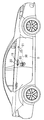
- FIG. 2 is a right side view of the passenger vehicle.
- FIG. 3 is a side view of the inside handle and latch mechanism of the front side door on the driver's seat side as seen from the passenger compartment side.
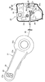
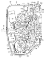
- FIG. 4 is an enlarged side view of the latch mechanism.
- FIG. 5 is a view showing a part of the latch mechanism along the line 5-5 in FIG. 4 with the door open with the cover plate removed from the casing.
- FIG. 6 is a view corresponding to FIG. 5 in a half door state.
- FIG. 7 is a diagram corresponding to FIG. 5 in the full latch state.
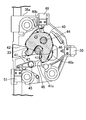
- FIG. 8 is a side view of the main part showing a part of the latch mechanism in the unlocked state with the cover member and the cover plate removed from the casing.
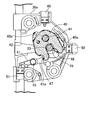
- FIG. 9 is a side view corresponding to FIG. 8 in the unlatched state by the operation of the latch releasing electric motor.
- FIG. 10 is a side view corresponding to FIG. 8 in the locked state.
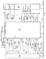
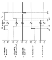
- FIG. 11 is a diagram showing the configuration of the control system.
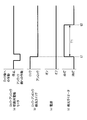
- FIG. 12 is a timing chart for explaining display control when changing from the locked state to the unlocked state when the power is off.
- FIG. 13 is a timing chart for explaining display control when changing from the locked state to the unlocked state when the power is on.
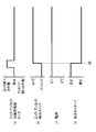
- FIG. 14 is a timing chart for explaining display control when the light emitting diode is turned on to change from the unlocked state to the locked state.
- FIG. 15 is a timing chart for explaining display control when the light-emitting diode is turned on and the power is turned off.
- FIG. 16 is a timing chart for explaining the operation control of the latch release electric motor.
- a driver's seat 18 is disposed, for example, on the right side of the front of the passenger compartment 17 of the passenger vehicle.
- An inside handle 21 for opening and closing the side door D is provided.
- an outer handle 19 for opening and closing the front side door D is provided on the outer surface of the front side door D on the driver's seat 18 side.
- a cylinder lock 20 is attached.
- the front side door D on the driver's seat 18 side has a latched state in which the closed state of the front side door D is held by engaging the vehicle body side, and the front side door D is opened.
- a latch mechanism 22 that can switch the unlatched state that can be switched is provided.
- the latch mechanism 22 is capable of forward and reverse rotation that exerts power to switch between an unlocked state in which the latched state can be released and a locked state in which the latched state cannot be released.
- An electric motor 23 for switching between lock and unlock and an electric motor 24 for releasing latch that exhibits power for releasing the latched state in the unlocked state are incorporated.
- the inside handle 21 is formed in a circular shape larger than the front support portion 21b, a grip portion 21a that extends long in the front-rear direction of the vehicle, a circular front support portion 21b that is connected to the front end of the grip portion 21a.
- a rear support portion 21c connected to the rear end of the grip portion 21a, and the front support portion 21b and the rear support portion 21c of the inside handle 21 that are inclined forwardly upward are provided on the driver seat side door D. Fixed to the inner surface.
- the locked state and the unlocked state of the latch mechanisms 22 of all the doors including the side door D on the driver's seat 18 side of the passenger vehicle are switched on the surface of the inside handle 21 facing the vehicle interior of the front support portion 21b.
- a lock / unlock switching switch 26 is provided.
- a push button 29 is disposed on the front upper side surface of the grip portion 21 a of the inside handle 21, and the vehicle user operates the push button when operating the latch release electric motor 24 of the latch mechanism 22.
- the cable 30 to be pulled in response to the pushing operation of the push button 29 is extended from the inside handle 21 to the latch mechanism 22 side.
- the casing 35 of the latch mechanism 22 is attached to the housing case 36 and a housing case 36 for housing the lock / unlock switching electric motor 23 and the latch releasing electric motor 24. And a metal cover plate 37.
- the housing case 36 can be attached to and detached from the case main body 38 so as to close the open end of the case main body 38 and a synthetic resin case main body 38 that is formed in a box shape that opens toward the passenger compartment 17 side.
- the housing case 36 is integrally provided with a projecting portion 36a that protrudes toward the inner surface of the front side door D on the free end side of the front side door D.
- the cover plate 37 is attached to the protrusion 36a.
- the protrusion 36a and the cover plate 37 are rotated in the closing direction (counterclockwise in FIG. 5) by engaging with a striker 33 (see FIGS. 6 and 7) fixed to the vehicle body.
- a latch 40 that can be moved, and a ratchet 41 that can be engaged with the latch 40 so as to hold the rotational position of the latch 40 are accommodated.
- An entrance groove 42 for allowing the striker 33 to enter is formed in the protrusion 36a, and an opening 43 corresponding to the entrance groove 42 is provided in the cover plate 37.
- the latch 40 is rotatably supported by a first support shaft 44 provided between the cover plate 37 and the protrusion 36a.
- the cover plate 37 and the protrusion 36a are provided with a second support shaft 45 having an axis parallel to the first support shaft 44 at a position sandwiching the entry groove 42 with the first support shaft 44,
- the ratchet 41 is rotatably supported on the second support shaft 45.
- the latch 40 is urged to rotate in a door opening direction (clockwise in FIG. 5) by a spring (not shown) that is contracted between the protrusion 36a.
- a spring not shown
- On the outer periphery of the latch 40 there are an engagement groove 46 for engaging the striker 33 that has entered the entry groove 42 when the latch 40 is at the rotation end in the door opening direction, and a full engagement step portion 47. And a half-engaging step 48.
- the ratchet 41 is integrally provided with an engagement arm portion 41a protruding toward the latch 40 so as to be able to engage with the full engagement step portion 47 and the half engagement step portion 48 of the latch 40.
- the ratchet 41 is rotated between a ratchet engagement position indicated by a solid line in FIG. 5 and a ratchet release position indicated by a chain line in FIG. 5 by the operation of the electric motor 24 for releasing latch.
- a ratchet lever 58 shown in FIG. 8 described later is interlocked and connected to the ratchet 41 so as to rotate together with the ratchet 41.
- the engagement arm portion of the ratchet 41 41a is in contact with a first elastic bulging portion 40a provided on the outer periphery of the half engagement step portion 48 in the latch 40, and is pushed by the striker 33 that has entered the entry groove 42 so that the latch 40 is closed (
- the striker 33 is engaged with the engagement groove 46 and the engagement arm portion 41 a is engaged with the half engagement step portion 48 as shown in FIG. 6.
- the latch 40 further rotates in the door closing direction, as shown in FIG.
- the engagement arm portion 41a is engaged with the full engagement step portion 47, and the front side door D is locked in a completely closed state, and becomes a full latch state.
- the latch mechanism 22 when the ratchet 41 is rotationally driven from the ratchet engagement position to the ratchet release position in the fully latched state, the latch mechanism 22 is in an unlatched state, and the front side door D is closed when the door is closed.
- the latch 40 As the front side door D is slightly opened by the reaction force of the waterproof seal interposed between the vehicle body D and the vehicle body, the latch 40 is also slightly rotated in the opening direction, and the front side door D is moved in the opening direction.
- the striker 33 moves in the entry groove 42 in response to the operation force being applied, the latch 40 rotates to the rotation end in the door opening direction shown in FIG.
- the protrusion 36a of the housing case 36 has the latch 40 between the rotation end in the door opening direction shown in FIG. 5 and the rotation position just before the half latch state shown in FIG.
- an unlatch switch 49 is attached which comes into contact with a second elastic bulge 40b provided on the outer periphery of the latch 40 and is turned on.
- a full latch switch 50 is attached, which comes into contact with the first elastic bulging portion 40a on the outer periphery of the latch 40 when it reaches the turning end in the door closing direction shown in FIG.
- a ratchet switch 51 is attached to the protrusion 36a. The ratchet switch 51 is in contact with the ratchet 41 while the ratchet 41 is in the ratchet engagement position.
- an open link 54, a release link 55, and a first cancel lever 56 are overlapped in order from the side opposite to the cover member 39 in a portion of the housing case 36 near the cover plate 37 in the case main body 38.
- the ratchet lever 58 that rotates together with the ratchet 41 moves upward while keeping the open link 54 or the release link 55 in a vertically extending posture, and comes into contact with and engages with the ratchet lever 58 from below.
- the ratchet 41 is rotated from the ratchet engagement position to the ratchet release position, whereby the rotation of the latch 41 in the opening direction is allowed, and the latch of the front side door D is latched. The state will be released.
- An open lever 59 that rotates according to the operation of the outside handle 19 disposed on the outer surface side of the front side door D is rotatably supported at the lower portion of the case main body 38 on the cover plate 37 side.
- the lower end of the open link 54 is connected to the open lever 59 so as to allow the open link 54 to rotate, and the open link 54 moves up and down in response to the rotation of the open lever 59. Operates on.
- the open link 54 is provided with a pressing portion 54a that can be brought into contact with and engaged with the ratchet lever 58 from below when the open link 54 is in a vertically extending posture as shown in FIG.
- the release link 55 is supported by the case main body 38 so as to be able to operate up and down.
- a guide wall 60 that guides the vertical movement of the release link 55 is provided on the case main body 38.
- a torsion spring 61 that urges the release link 55 toward the side that slides against the guide wall 60 is provided between the case main body 38 and the release link 55.
- a link pin 62 is planted on the upper part of the release link 55, and a pressing portion 55 a that can contact and engage with the ratchet lever 58 from below is provided on the release link 55.
- a contact surface 63 that can contact the link pin 62 from the opposite side and the lower side of the guide wall 60 is formed at the upper end portion of the first cancel lever 56, and the link pin 62 is opposite to the cover plate 37.
- a locking plate portion 64 facing from the side is provided.
- a lower end portion of the first cancel lever 56 is rotatably connected to one end portion of the release lever 65, and an intermediate portion of the release lever 65 rotates to operate the first cancel lever 56 up and down. It is supported by the case main body 38 through the third support shaft 66 as possible.
- the case main body 38 is fixedly provided with the latch release electric motor 24, and a worm wheel 69 that meshes with a worm gear 68 provided on the output shaft 67 of the latch release electric motor 24 is a third one. It is rotatably supported by the case main body 38 via a fourth support shaft 70 having an axis parallel to the support shaft 66.
- the worm wheel 69 is provided with a cam 71 that rotates together with the worm wheel 69, and a pin 72 that slides on the cam 71 is implanted at the other end of the release lever 65.
- a torsion spring 73 is provided between the case main body 38 and the release lever 65 to urge the release lever 65 in a direction in which the pin 72 is slidably contacted with the cam 71.
- the lock / unlock switching electric motor 23 is fixedly disposed above the case main body 38 above the latch releasing electric motor 24, and the output of the lock / unlock switching electric motor 23 is fixed.
- a worm wheel 78 meshing with a worm gear 77 provided on the shaft 76 is rotatably supported on the case main body 38 via a fifth support shaft 79 parallel to the fourth support shaft 70.
- the worm wheel 78 is provided with an engaging projection 80 that is offset from the central axis thereof, and a fan-shaped first locking lever 84 having a locking recess 82 on the outer periphery that can engage the engaging projection 80 is provided.
- a second locking lever 86 that is rotatably supported by the case main body 38 via a sixth support shaft 85 parallel to the fifth support shaft 79 and rotates together with the first locking lever 84 is also connected via the sixth support shaft 85.
- the case main body 38 is rotatably supported.
- the second locking lever 86 is inserted through a first pin 87 extending in the vertical direction and inserted into a long hole 89 provided in the open link 54 and a rectangular opening 90 provided in the first cancel lever 56. And a second pin 88 is provided.
- the first cancel lever 56 is urged between the case main body 38 and the first cancel lever 56 in a direction in which the side edge of the opening 90 opposite to the cover plate 37 is brought into contact with the second pin 88.
- a torsion spring 91 is provided.
- the lock / unlock switching electric motor 23 has the worm wheel in which the engagement protrusion 80 is engaged with the engagement recess 82. 8 is stopped by rotating to the position shown in FIG. 8, and in this state, the second locking lever 86 is in a state of maximum rotation in the counterclockwise direction of FIG. 8 around the axis of the sixth support shaft 85. .
- the open link 54 and the first cancel lever 56 are vertically extended as shown in FIG. 8, and the contact surface 63 of the upper end portion of the first cancel lever 56 contacts the link pin 62 from below.
- the pressing portion 54a of the open link 54 can also come into contact with the ratchet lever 58 from below.
- the lock / unlock switching electric motor 23 is The worm wheel 78 is rotated counterclockwise from the state 8 and the worm wheel 78 having the engagement protrusion 80 engaged with the locking recess 82 is rotated to the position shown in FIG. In this state, the second locking lever 86 is in the state of being rotated to the maximum extent clockwise in FIG. 10 around the axis of the sixth support shaft 85. As a result, the open link 54 and the first cancel lever 56 are inclined in a direction away from the guide wall 60 from an attitude extending in the vertical direction.
- a first cylinder lever 108 that rotates in response to a key operation of the cylinder lock 20 attached to the outside handle 19 is supported on the upper portion of the case main body 38 via a seventh support shaft 106.
- the cylinder lever 108 is provided with an arc-shaped connecting hole 107 centered on the axis of the seventh support shaft 106.
- a second cylinder lever 109 that overlaps the first cylinder lever 108 is supported on the seventh support shaft 106 so as to be rotatable relative to the first cylinder lever 108, and the second cylinder lever 109 has the connection hole 107.
- a connecting pin 105 to be inserted through is installed.
- the second cylinder lever 109 is connected to one end of a third cylinder lever 111 rotatably supported by the case main body 38 via an eighth support shaft 110 having an axis parallel to the seventh support shaft 106. It is connected via.
- the other end of the third cylinder lever 111 is one end of a fourth cylinder lever 114 that is rotatably supported by the case main body 38 via a ninth support shaft 113 having an axis parallel to the eighth support shaft 110.
- the other end of the fourth cylinder lever 114 is connected to the first locking lever 84 via the connection pin 116.
- the second to fourth cylinder levers 109, 111, 114 rotate in the same manner as when the cylinder lock 20 is operated by the operation of the electric motor 23 for switching between lock and unlock.
- a lock / unlock detection switch 117 for detecting whether the mechanism 22 is in an unlocked state or a locked state is switched by contacting / separating the detected portion 111 a provided integrally with the third cylinder lever 111. It is attached to the case main body 38 so as to change the mode.
- the cable 30 that transmits mechanical force to the latch mechanism 22 side according to the operation of the push button 29 disposed on the inside handle 21 of the front side door D is connected to the inner side of the outer cable 92.
- the cable 93 is inserted, and the end of the outer cable 92 on the latch mechanism 22 side is supported by the case main body 38 of the housing case 36.
- a mechanical operation force input lever 95 to which a mechanical latch release operation force is transmitted from the push button 29 of the inside handle 21 is rotated via a tenth support shaft 96 to the cover member 39 in the housing case 36. It is supported as possible.
- the mechanical operating force input lever 95 integrally includes a connecting arm portion 95a in which an end portion of the inner cable 93 protruding from the outer cable 92 is connected to a tip portion. It is rotatably supported on the cover member 39 via a tenth support shaft 96 while the most part excluding the front end portion is disposed inside the cover member 39.
- the distal end portion of the connecting arm portion 95a protrudes outward from the cover member 39, and the inner cable 93 is connected to the distal end portion of the connecting arm portion 95a.
- the case main body 38 in the housing case 36 is interlocked with and connected to the mechanical operating force input lever 95 and is rotated together with the mechanical operating force input lever 95 to release the latch.
- a lever 97 is rotatably supported via an eleventh support shaft 98 coaxial with the tenth support shaft 96, and the latch releasing operation lever 97 is connected to a lower end portion of the interlocking link 101 extending vertically.
- the connecting arm part 97a connected via the connecting arm part 97a and the detected arm part 97b extending to the opposite side of the connecting arm part 97a are integrally provided.
- a torsion spring 103 is provided between the connecting arm portion 97a and the lower end portion of the interlocking link 101.
- the interlocking link 101 rotates around the axis of the connecting pin 102 in the counterclockwise direction of FIGS.
- the rotation end of the interlocking link 101 in the direction of rotation biasing by the torsion spring 103 is regulated by coming into contact with the first locking lever 84.
- the first locking lever 84 is interlocked and connected to the intermediate portion of the interlocking link 101 when the interlocking link 101 moves upward from the lowest limit position by a predetermined stroke, and when the interlocking link 101 further moves upward.
- the first locking lever 84 and the second locking lever 86 are driven to rotate counterclockwise in FIGS.
- the second cancel lever 100 is rotatably supported on the case main body 38 via the twelfth support shaft 99 above the open link 54, the release link 55 and the first cancel lever 56.
- the second cancel lever 100 is formed by integrating a pressing arm portion 100a facing the locking plate portion 64 of the first cancel lever 56 from the guide wall 60 side and a connecting arm portion 100b positioned above the interlocking link 101.
- the distal end portion of the connecting arm portion 100b and the intermediate portion in the longitudinal direction of the open link 54 are connected via a cancel link 104.
- the latch mechanism 22 detects a manipulation of the push button 29 disposed on the inside handle 21 of the front side door D and operates a pair of latches for operating the electric motor 24 for releasing the latch. Release intention detection switches 118 and 119 are attached.
- Both latch release intention detection switches 118 and 119 are linked to and connected to a mechanical operating force input lever 95 that is connected to the cable 30 that is pulled when the push button 29 of the inside handle 21 is pressed.
- the detected arm portion 97b of the latch release operation lever 97 that rotates together with the input lever 95 is detected, and one latch release intention detection switch 118 presses the push button 29 to release the latch release operation lever 97.
- the other latch release intention detection switch 119 is pushed by the detected arm portion 97b when the latch release operation lever 97 is rotated.
- the latch release operation lever 97 does not rotate when the push button 29 is not operated.
- latch release intention detection switch when a single latch release intention detection switch is used, for example, it may occur that the switch is turned on by itself due to a system failure and the latch release electric motor 24 operates undesirably.
- the latch release electric motor 24 By providing two latch release intention detection switches 118 and 119 for redundancy, the latch release electric motor 24 can be prevented from operating undesirably.
- the case main body 38 includes an initial position cam switch 120 and a ratchet release position cam switch 121 that detect the rotational position of the cam 71 together with the worm wheel 69 according to the operation of the latch release electric motor 24.
- the worm wheel 69 is attached at a spaced position around the worm wheel 69.
- the initial position cam switch 120 is for determining the initial position of the latch release electric motor 24, and the ratchet 41 is in a state where the latch release electric motor 24 is in the initial position. In position.
- the ratchet release position cam switch 121 is used for releasing the latch until the unlatching state is detected by the unlatch switch 49 when the latch release electric motor 24 is operated to move the ratchet 41 to the ratchet release position. In order to continue the operation of the electric motor 24, it is arranged to detect a predetermined rotational position of the cam 71 corresponding to the ratchet release position of the ratchet 41.
- the operation of the latch release electric motor 24 is controlled by a latch control unit 122, and the operation of the lock / unlock switching electric motor 23 is controlled by a central control unit 123.
- the central control unit 122 and the central control unit 123 are connected to the smart control unit 124 via the CAN-H line 126 and the CAN-L line 127.
- the outside handle 19 has a built-in LF antenna 128 for exchanging signals with a portable device carried by the vehicle user, and is turned on by grasping a predetermined position of the outside handle 19.
- Two unlock switches 129 and 130 and a lock switch 131 which is turned on by touching another predetermined position of the outside handle 19, and the cylinder lock attached to the out handle 19 is provided.
- 20 is provided with a key switch 132 for detecting whether the cylinder lock 20 is operated on the lock side or the unlock side.
- the latch control unit 122 includes an unlatch switch 49, a full latch switch 50, a ratchet switch 51, a latch release intention detection switch 118, an initial position cam switch 120, and a ratchet release disposed in the casing 35 of the latch mechanism 22. On / off signals from the position cam switch 121 and the unlock switch 129 are input.
- the LF antenna 128 is connected to the smart control unit 124, and the latch release intention detection switch 119 disposed in the casing 35 of the latch mechanism 22 and the unlock provided in the outside handle 19. On / off signals from the switch 130 and the lock switch 131 are input.
- the central control unit 123 includes a signal indicating whether the lock / unlock detection switch 117 disposed in the casing 35 of the latch mechanism 22 detects a locked state or an unlocked state, the inside A signal indicating whether the lock / unlock switching switch 26 provided on the handle 21 is operated to a locked state or an unlocked state, and the key switch 132 attached to the cylinder lock 20 is A signal indicating which of the unlocking side is operated is input.
- the lock / unlock switching electric motor 23 is activated to unlock the vehicle.
- the latch releasing electric motor 24 operates to release the latched state.
- the two unlock switches 129 and 130 are provided on the outside handle 19 in order to achieve redundancy in the same manner as the two latch release intention detection switches 118 and 119 are provided on the latch mechanism 22. If a single unlock switch is used, the switch may be turned on by itself due to a system failure, for example, and the unlatching electric motor 24 may be operated undesirably. By providing the unlock switches 129 and 130, it is possible to prevent the unlatching electric motor 24 from operating undesirably.
- the latch control unit 122 supplies at least the output of the lock / unlock detection switch 117 with energization to one light emitting diode 135 which is an electric display means for indicating that the latch mechanism 22 is unlocked by energization.
- the electric power from the battery 136 is supplied to the latch control unit 122, and the electric power from the battery 136 is also supplied to the smart control unit 124 via the latch control unit 122.
- the light emitting diode 135 is disposed on the inner surface side of the front side door D so that the light emitting diode 135 can be viewed from outside the vehicle in a closed state of the front side door D. In this embodiment, FIG. As shown, the light emitting diode 135 is disposed at the lower edge of the window 138 on the inner surface of the front side door D.
- the dashboard 139 disposed in the front portion of the passenger compartment 17 is energized to the vehicle-mounted equipment that is activated by energization when the driver sitting on the driver's seat 18 performs a pressing operation.
- An engine switch 137 that is a switch that switches between a power-off state in which the power is turned off and a power-on state that enables energization of the on-vehicle equipment is provided.
- the engine switch 137 enables energization to the accessory mounted on the vehicle and energizes the ignition coil of the engine, and enables energization to the accessory but cuts off the energization to the ignition coil.
- the engine switch 137 is interposed between the battery 136 and the latch control unit 122 as shown in FIG. 11. Is done.
- the ignition terminal of the latch control unit 122 is conducted to the battery 136, and the engine switch
- the accessory terminal of the latch control unit 122 energizes the battery 136, and latch control is performed.
- the unit 122 determines that a state in which any of the ignition terminal and the accessory terminal conducts to the battery 136 is a power-on state, and both the ignition terminal and the accessory terminal are the battery 136. The state of being cut off is determined that the power-off state.
- the latch control unit 122 starts energizing the light emitting diode 135 at the time of switching when the lock / unlock detection switch 117 detects that the lock / unlock detection switch 117 is switched from the locked state to the unlocked state in the power-off state.
- the power supply to the light emitting diode 135 is cut off after a first predetermined time, for example, 1 minute from the switching time, but when the power is on, the lock / unlock detection switch As long as it is detected that 117 is in the unlocked state, the energized state of the light emitting diode 135 is maintained even after the elapse of the first predetermined time.
- the energization control of the light emitting diode 135 by the latch control unit 122 will be described with reference to FIGS. 12 to 15.
- the electric motor 23 for switching between lock and unlock is In response to the operation to the unlock side, the light emitting diode 135 is turned on in response to detecting that the lock / unlock detection switch 117 is switched from the locked state to the unlocked state at time t1.
- the power supply to the light emitting diode 135 is cut off, and the light emitting diode 135 is turned off.
- the lock / unlock detection switch 117 when the power is on, the lock / unlock detection switch 117 is moved from the locked state at time t3 in response to the operation of the lock / unlock switching electric motor 23 to the unlock side.
- the light emitting diode 135 is turned on in response to detecting that it has been switched to the unlocked state, and the light emitting diode 135 is still in the power-on state after time t4 when the first predetermined time T1 has elapsed since the lighting. Is continuously energized, and the light emitting diode 135 remains lit.
- the lock / unlock detection switch 117 detects the unlocked state in the power-on state
- the light-emitting diode 135 remains lit.
- the light emitting diode 135 is detected in response to the lock / unlock detection switch 117 detecting that the lock state is switched from the unlock state to the lock state at time t5. Is turned off, and the light emitting diode 135 is turned off.
- the lock / unlock detection switch 117 detects the unlocked state in the power-on state, the light-emitting diode 135 remains lit, but the power-off state is maintained in this state. Then, at the time t7 when the first predetermined time T1 has elapsed from the time t6 when the light is turned off, the power supply to the light emitting diode 135 is cut off, and the light emitting diode 135 is turned off.
- the latch control unit 122 starts the operation of the latch release electric motor 24 so as to rotate the ratchet 41 from the ratchet engagement position to the ratchet release position, and then the ratchet release position cam switch 121.
- the operation of the electric motor 24 for latch release is stopped, and a second predetermined time, for example, 5 seconds has elapsed since the stop.
- the latch release electric motor 24 is operated so as to rotationally drive the ratchet 41 to the ratchet engagement position.
- the operation control of the latch release electric motor 24 will be described with reference to FIG. 16 in the fully latched state in which the ratchet 41 is engaged with the latch 40 when the front side door D is completely closed.
- the latch release intention detection switches 118 and 119 detect the vehicle driver's intention to release the latch at time t8 when the full latch switch 50 is in the ON state
- the latch release electric motor 24 rotates the ratchet 41 toward the ratchet release position.
- the latching state is released by the rotation of the ratchet 41 corresponding to the operation of the electric motor 24 for releasing the latch, and the latch 40 biased in the opening direction is slightly rotated.
- the full latch switch 50 is turned off, and at a subsequent time t10, the ratchet release cam switch Chi 121 actuation of the unlatching electric motor 24 is stopped in response to an ON state, the ratchet 41 is held to the ratchet release position.
- the latch release electric motor 24 rotates the ratchet 41 toward the ratchet engagement position.
- the ratchet release position cam switch 121 is turned off at time t12 in accordance with the operation of the latch release electric motor 24, the initial position cam switch 120 is changed from the off state to a short time.
- the operation of the latch release electric motor 24 is stopped at time t13 when the time is turned on after the time is turned on.
- the operation time T3 of the latch release electric motor 24 for driving the ratchet 41 to rotate from the ratchet engagement position to the ratchet release position is 0.07 seconds, for example.
- the operation time T4 of the latch release electric motor 24 for rotationally driving from the ratchet release position to the ratchet engagement position is, for example, 0.12 seconds, and T3 ⁇ T4. This is because the operation of the latch release electric motor 24 when rotating from the ratchet engagement position to the ratchet release position is stopped in response to the ratchet release position cam switch 121 being turned on.
- the latch control unit 122 starts the operation of the latch release electric motor 24 so as to rotate the ratchet 41 from the ratchet engagement position to the ratchet release position, and then the ratchet 41 is moved to the ratchet release position.
- cam switch 121 detects that the latch release position is detected and the operation of the latch release electric motor 24 is stopped.
- the ratchet engaging position is immediately moved to the ratchet engagement position side even during the lapse of the second predetermined time T2.
- the electric motor 24 for releasing the latch is operated so that the ratchet 41 is rotated.
- the latch mechanism 22 provided on the front side door D cannot be unlocked and the latched state can be released.
- the lock / unlock switching electric motor 23 that exhibits the power for switching the locked state and the lock / unlock detection switch that detects whether the latch mechanism 22 is in the unlocked state or the locked state.
- 117, and energization of the light emitting diode 135, which indicates that the latch mechanism 22 is unlocked by energization, is controlled by the latch control unit 122 based on at least the output of the lock / unlock detection switch 117.
- the latch control unit 122 is activated by energization.
- the lock / unlock detection switch 117 detects that the switch from the lock state to the unlock state is detected. Is turned off after a first predetermined time T1 has elapsed since the switching point, but the lock / unlock detection switch 117 is in the unlocked state when the vehicle-mounted device is in a power-on state. As long as it is detected that the light-emitting diode 135 is energized, the energized state of the light-emitting diode 135 is maintained even after the first predetermined time T1 has elapsed.
- the front side door D cannot be It avoids erroneously recognized that the despite the locked state is in the locked state, undesirably front side door D can be prevented from being opened.
- the electric display means is composed of one light emitting diode 135, it is possible to easily secure a space for arranging the electric display means while reducing power consumption. Further, since the light emitting diode 135 is disposed on the inner surface side of the front side door D so that the light emitting diode 135 can be viewed from outside the vehicle when the front side door D is closed, the light emitting diode 135 can be viewed from outside the vehicle. Thus, the unlocked state and the locked state can be easily confirmed even from outside the vehicle.
- the latch 40 that can be engaged with the striker 33 on the vehicle body side as the front side door D is rotated to the closing side has a ratchet 41 in the latch engagement position to completely close the front side door D.
- the latch release electric motor 24 can be engaged in a state and a half door state, and the ratchet 41 is rotationally driven between the engagement position and the ratchet release position for releasing the engagement with the latch 40.
- the latch release intention detection switches 118 and 119 detect the vehicle driver's intention to release the latch.
- the latch control unit 122 controls the ratchet 41 so as to rotate from the ratchet engagement position to the ratchet release position.
- the latch control unit 122 causes the ratchet 41 to move to the ratchet release position after the latch release electric motor 24 starts operating so as to rotate the ratchet 41 from the ratchet engagement position to the ratchet release position.
- the ratchet release position cam switch 121 detects the presence of the latch release electric motor 24 and stops the operation of the latch release electric motor 24, the ratchet 41 is moved to the ratchet engagement position after a second predetermined time T2.
- the latch release electric motor 24 is operated so as to rotate.
- the ratchet 41 is engaged with the latch 40 after the second predetermined time T2 has elapsed, and the front side door D It is possible to prevent the situation where the front side door D opens undesirably as much as possible.
- the latch control unit 122 detects that the ratchet 41 is in the ratchet release position by the ratchet release position cam switch 121 and stops the operation of the latch release electric motor 24 for a second predetermined time.
- the unlatch switch 49 detects the rotation of the front side door D to the open side before T2 elapses
- the latch release is performed so that the ratchet 41 is immediately driven to rotate to the ratchet engagement position side.
- the electric motor 24 is operated. Therefore, when the front side door D is closed before the second predetermined time T2 elapses after the latched state is released and the front side door D is opened, the ratchet 41 is ratcheted.
- the front side door D cannot be held in the closed state when it is in the release position, the front side door D can be engaged with the latch 40 even if the front side door D is quickly closed. Can be kept closed.
- the light emitting diode 135 is disposed on the lower edge of the window 138 on the inner surface of the front side door D.
- the lock / unlock switching switch provided on the inside handle 21. It may be arranged in the central part of 26.
Abstract
A controller for energizing a vehicle door lock indicator, wherein, in a power-supply-deactivated state in which an in-vehicle device activated by being energized is not energized, an energizing-controlling means (122) stops energizing an electric indicating means (135) initially energized at a switching time at which a locking-state detecting means (117) detects that a door has switched from being locked to being unlocked, the energizing-controlling means (122) stopping energizing of the electric indicating means (135) once a predetermined amount of time has elapsed following the switching time; however, in a power-supply-activated state in which the in-vehicle device can be energized, the energizing-controlling means (122) keeps the electric indicating means (135) energized even after the predetermined time has elapsed as long as the locking-state detecting means (117) has detected that the door is unlocked. Consequently, in the power-supply-activated state in which it is possible to energize the in-vehicle device activated by being energized, the fact that the door is unlocked will be clearly indicated as long as the locking-state detecting means (117) has detected that the door is unlocked, and the door can be prevented from being opened unintentionally.
Description
本発明は、ドアに設けられるラッチ機構のラッチ状態を解除することを可能としたアンロック状態ならびに前記ラッチ状態を解除することを不能としたロック状態を切換える動力を発揮する電気アクチュエータと、前記ラッチ機構が前記アンロック状態および前記ロック状態のいずれの状態になっているかを検出するロック状態検出手段と、通電によって前記ラッチ機構がアンロック状態にあることを表示する電気表示手段と、少なくとも前記ロック状態検出手段の出力に基づいて前記電気表示手段への通電を制御する通電制御手段とを備える車両のドアロック表示通電制御装置に関する。
The present invention relates to an electric actuator that exerts power to switch between an unlocked state in which a latched state of a latch mechanism provided in a door can be released and a locked state in which the latched state cannot be released, and the latch A lock state detecting means for detecting whether the mechanism is in the unlocked state or the locked state; an electric display means for displaying that the latch mechanism is unlocked by energization; and at least the lock The present invention relates to a vehicle door lock display energization control device including energization control means for controlling energization to the electrical display means based on an output of a state detection means.
ドアに設けられるラッチ機構がアンロック状態にあるときに、電気表示手段であるランプを点灯させ、ロック状態になったときには前記ランプを消灯させるようにしたものが特許文献1で知られている。また特許文献1で開示されたものでは、アンロック状態からロック状態に切換えない限り、前記ランプが点灯し続けることで電力を消費してしまうので、電力浪費を防止するために、電気表示手段である発光素子の点灯後の時間経過をタイマで計測し、所定時間の経過後に発光素子を消灯するようにしたものが、特許文献2で知られている。
Patent Document 1 discloses that a lamp as an electric display means is turned on when a latch mechanism provided on a door is in an unlocked state, and the lamp is turned off when the door is in a locked state. Further, in the device disclosed in Patent Document 1, unless the lamp is switched from the unlocked state to the locked state, the lamp continues to be lit to consume electric power. Patent Document 2 discloses a technique in which a time elapsed after lighting a certain light emitting element is measured by a timer and the light emitting element is turned off after a predetermined time has elapsed.
ところが、上記特許文献2で開示されるように、電気表示手段への通電状態をその通電開始後の所定時間の経過後に遮断すると、所定時間の経過後にはドアがアンロック状態およびロック状態のいずれの状態にあるか分からなくなり、電気表示手段が非通電状態にあるのでドアがアンロック状態であるにもかかわらずロック状態であると誤認してしまう可能性が高く、誤ってドアを開放させてしまう虞がある。
However, as disclosed in Patent Document 2, when the energized state of the electric display means is interrupted after a predetermined time has elapsed since the start of energization, the door is either unlocked or locked after the predetermined time has elapsed. Since the electrical display means is in a non-energized state, there is a high possibility that the door will be misidentified as being locked even though it is unlocked. There is a risk of it.
本発明は、かかる事情に鑑みてなされたものであり、通電によって活性化する車両搭載機器への通電を可能とした電源オン状態にあるときにはロック状態検出手段がアンロック状態を検出している限りアンロック状態であることを明確に表示して、不所望にドアが開放してしまうことを防止し得るようにした車両用のドアロック表示通電制御装置を提供することを目的とする。
The present invention has been made in view of such circumstances, as long as the lock state detection means detects the unlocked state when the vehicle-on-device activated by energization is in a power-on state. It is an object of the present invention to provide a vehicle door lock display energization control device that clearly displays an unlocked state and prevents the door from being undesirably opened.
上記目的を達成するために、本発明は、ドアに設けられるラッチ機構のラッチ状態を解除することを可能としたアンロック状態ならびに前記ラッチ状態を解除することを不能としたロック状態を切換える動力を発揮する電気アクチュエータと、前記ラッチ機構が前記アンロック状態および前記ロック状態のいずれの状態になっているかを検出するロック状態検出手段と、通電によって前記ラッチ機構がアンロック状態にあることを表示する電気表示手段と、少なくとも前記ロック状態検出手段の出力に基づいて前記電気表示手段への通電を制御する通電制御手段とを備える車両のドアロック表示通電制御装置において、前記通電制御手段は、通電によって活性化する車両搭載機器への通電を遮断した電源オフ状態では前記ロック状態検出手段が前記ロック状態からアンロック状態に切換わったことを検出した切換時点で通電を開始した前記電気表示手段への通電を前記切換時点から所定時間の経過後に遮断するものの、前記車両搭載機器への通電を可能とした電源オン状態にあるときには前記ロック状態検出手段が前記アンロック状態であることを検出している限り前記電気表示手段への通電状態を前記所定時間の経過後も持続することを第1の特徴とする。
In order to achieve the above object, the present invention provides a power for switching between an unlocked state in which a latched state of a latch mechanism provided in a door can be released and a locked state in which the latched state cannot be released. An electric actuator to be exhibited, a lock state detecting means for detecting whether the latch mechanism is in the unlocked state or the locked state, and displaying that the latch mechanism is unlocked by energization In a vehicle door lock display energization control device comprising: an electric display means; and an energization control means for controlling energization to the electric display means based on at least the output of the lock state detection means. In the power-off state in which the energization of the on-vehicle equipment to be activated is cut off, Is switched off from the locked state to the unlocked state, the power supply to the electric display means that has started energization at the time of switching is cut off after a predetermined time has elapsed from the time of switching. As long as the lock state detection means detects that the power supply is in the power-on state, the electrical display means is maintained in the power supply state even after the predetermined time has elapsed. First feature.
また本発明は、第1の特徴の構成に加えて、前記電気表示手段が1個の発光ダイオードから成ることを第2の特徴とする。
Further, in addition to the configuration of the first feature, the present invention has a second feature that the electric display means is composed of one light emitting diode.
さらに本発明は、第1または第2の特徴の構成に加えて、前記電気表示手段が、前記ドアの閉鎖状態で車外から視認することを可能として前記ドアの内面側に配設されることを第3の特徴とする。
Furthermore, in addition to the configuration of the first or second feature, the present invention is such that the electric display means is disposed on the inner surface side of the door so as to be visible from outside the vehicle when the door is closed. The third feature.
なお実施の形態のロック・アンロック切換用電動モータ23が本発明の電気アクチュエータに対応し、実施の形態のロック・アンロック検出スイッチ117が本発明のロック状態検出手段に対応し、実施の形態のラッチ制御ユニット122が本発明の通電制御手段に対応し、第1の所定時間T1が本発明の所定時間に対応する。
The lock / unlock switching electric motor 23 of the embodiment corresponds to the electric actuator of the present invention, and the lock / unlock detection switch 117 of the embodiment corresponds to the lock state detection means of the present invention. The latch control unit 122 corresponds to the energization control means of the present invention, and the first predetermined time T1 corresponds to the predetermined time of the present invention.
本発明の第1の特徴によれば、電源オン状態にあるときにはロック状態検出手段がアンロック状態であることを検出している限り電気表示手段への通電が保持され、アンロック状態であることを明確に表示するので、ロック状態であると誤って認識してしまうことを回避し、不所望にドアが開放してしまうことを防止することができる。
According to the first feature of the present invention, when the power-on state is detected, the energization of the electrical display means is maintained as long as the lock state detection means detects that the lock state detection means is unlocked, and the unlock state is maintained. Is clearly displayed, so that it can be prevented that the door is erroneously recognized as being locked, and the door can be prevented from being undesirably opened.
また本発明の第2の特徴によれば、電気表示手段として1つの発光ダイオードを用いるので、電力消費量を少なくしつつ電気表示手段の配置スペースを容易に確保することができる。
Further, according to the second feature of the present invention, since one light emitting diode is used as the electric display means, it is possible to easily secure a space for arranging the electric display means while reducing power consumption.
さらに本発明の第3の特徴によれば、電気表示手段を車外から視認可能とすることで、車外からでもアンロック状態およびロック状態を容易に確認することができる。
Furthermore, according to the third feature of the present invention, by making the electric display means visible from outside the vehicle, the unlocked state and the locked state can be easily confirmed even from outside the vehicle.
22・・・ラッチ機構
23・・・電気アクチュエータであるロック・アンロック切換用電動モータ
117・・・ロック状態検出手段であるロック・アンロック検出スイッチ
122・・・通電制御手段であるラッチ制御ユニット
135・・・電気表示手段である発光ダイオード
D・・・前部サイドドア
T1・・・第1の所定時間 DESCRIPTION OFSYMBOLS 22 ... Latch mechanism 23 ... Electric motor 117 for lock / unlock switching which is an electric actuator ... Lock / unlock detection switch 122 which is lock state detection means ... Latch control unit which is energization control means 135: Light-emitting diode D that is an electric display means ... Front side door T1 ... First predetermined time
23・・・電気アクチュエータであるロック・アンロック切換用電動モータ
117・・・ロック状態検出手段であるロック・アンロック検出スイッチ
122・・・通電制御手段であるラッチ制御ユニット
135・・・電気表示手段である発光ダイオード
D・・・前部サイドドア
T1・・・第1の所定時間 DESCRIPTION OF
以下、本発明の実施の形態について添付の図1~図16を参照しながら説明する。
Hereinafter, embodiments of the present invention will be described with reference to FIGS. 1 to 16.
先ず図1において、乗用車両の車室17内のたとえば前部右側には運転席18が配置され、運転席18側の前部サイドドアDの内面には、運転席18の車両ユーザが前記前部サイドドアDを開閉操作するためのインサイドハンドル21が設けられる。
First, in FIG. 1, a driver's seat 18 is disposed, for example, on the right side of the front of the passenger compartment 17 of the passenger vehicle. An inside handle 21 for opening and closing the side door D is provided.
図2を併せて参照して、前記運転席18側の前部サイドドアDの外面には、該前部サイドドアDを開閉操作するためのアウトサイドハンドル19が設けられ、このアウトハンドル19にシリンダ錠20が付設される。また前記運転席18側の前部サイドドアDには、その前部サイドドアDの閉じ状態を車体側に係合することで保持するラッチ状態ならびに前記前部サイドドアDを開放操作することを可能としたアンラッチ状態を切り換え可能としたラッチ機構22が配設される。
Referring also to FIG. 2, an outer handle 19 for opening and closing the front side door D is provided on the outer surface of the front side door D on the driver's seat 18 side. A cylinder lock 20 is attached. Further, the front side door D on the driver's seat 18 side has a latched state in which the closed state of the front side door D is held by engaging the vehicle body side, and the front side door D is opened. A latch mechanism 22 that can switch the unlatched state that can be switched is provided.
図3において、前記ラッチ機構22には、そのラッチ状態を解除することを可能としたアンロック状態ならびに前記ラッチ状態を解除することを不能としたロック状態を切換える動力を発揮する正逆回転自在のロック・アンロック切換用電動モータ23と、アンロック状態でラッチ状態を解除するための動力を発揮するラッチ解除用電動モータ24とが内蔵される。
In FIG. 3, the latch mechanism 22 is capable of forward and reverse rotation that exerts power to switch between an unlocked state in which the latched state can be released and a locked state in which the latched state cannot be released. An electric motor 23 for switching between lock and unlock and an electric motor 24 for releasing latch that exhibits power for releasing the latched state in the unlocked state are incorporated.
前記インサイドハンドル21は、車両の前後方向に長く延びる把持部21aと、該把持部21aの前端に連設される円形の前部支持部21bと、前部支持部21bよりも大きな円形に形成されて前記把持部21aの後端に連設される後部支持部21cとから成り、前上がりに傾斜した前記インサイドハンドル21の前部支持部21bおよび後部支持部21cが前記運転席側サイドドアDの内面側に固定される。
The inside handle 21 is formed in a circular shape larger than the front support portion 21b, a grip portion 21a that extends long in the front-rear direction of the vehicle, a circular front support portion 21b that is connected to the front end of the grip portion 21a. A rear support portion 21c connected to the rear end of the grip portion 21a, and the front support portion 21b and the rear support portion 21c of the inside handle 21 that are inclined forwardly upward are provided on the driver seat side door D. Fixed to the inner surface.
前記インサイドハンドル21における前部支持部21bの車室内に臨む面には、乗用車両の前記運転席18側のサイドドアDを含む全てのドアのラッチ機構22…のロック状態およびアンロック状態を切換えるためのロック・アンロック切換用スイッチ26が配設される。
The locked state and the unlocked state of the latch mechanisms 22 of all the doors including the side door D on the driver's seat 18 side of the passenger vehicle are switched on the surface of the inside handle 21 facing the vehicle interior of the front support portion 21b. For this purpose, a lock / unlock switching switch 26 is provided.
また前記インサイドハンドル21における把持部21aの前部上側面にはプッシュボタン29が配置されており、車両ユーザは、前記ラッチ機構22の前記ラッチ解除用電動モータ24を作動させる際には前記プッシュボタン29を押し込めばよく、そのプッシュボタン29の押し込み操作に応じて牽引されるケーブル30が前記インサイドハンドル21から前記ラッチ機構22側に延出される。
Further, a push button 29 is disposed on the front upper side surface of the grip portion 21 a of the inside handle 21, and the vehicle user operates the push button when operating the latch release electric motor 24 of the latch mechanism 22. The cable 30 to be pulled in response to the pushing operation of the push button 29 is extended from the inside handle 21 to the latch mechanism 22 side.
図4を併せて参照して、前記ラッチ機構22のケーシング35は、前記ロック・アンロック切換用電動モータ23および前記ラッチ解除用電動モータ24を収容する収容ケース36と、該収容ケース36に取付けられる金属製のカバープレート37とを有する。前記収容ケース36は、前記車室17側に向けて開放した函状に形成される合成樹脂製のケース主体38と、そのケース主体38の開放端を閉じるようにしてケース主体38に着脱可能に取付けられる合成樹脂製のカバー部材39とから成り、この収容ケース36には、前記前部サイドドアDの遊端側で該前部サイドドアDの内面側に突出する突部36aが一体に設けられており、前記カバープレート37は前記突部36aに取付けられる。
Referring also to FIG. 4, the casing 35 of the latch mechanism 22 is attached to the housing case 36 and a housing case 36 for housing the lock / unlock switching electric motor 23 and the latch releasing electric motor 24. And a metal cover plate 37. The housing case 36 can be attached to and detached from the case main body 38 so as to close the open end of the case main body 38 and a synthetic resin case main body 38 that is formed in a box shape that opens toward the passenger compartment 17 side. The housing case 36 is integrally provided with a projecting portion 36a that protrudes toward the inner surface of the front side door D on the free end side of the front side door D. The cover plate 37 is attached to the protrusion 36a.
図5において、前記突部36aおよび前記カバープレート37間には、車体側に固定されるストライカ33(図6および図7参照)との係合によって閉扉方向(図5の反時計方向)に回動することを可能としたラッチ40と、該ラッチ40の回動位置を保持するようにしてラッチ40に係合し得るラチェット41とが収容される。
In FIG. 5, the protrusion 36a and the cover plate 37 are rotated in the closing direction (counterclockwise in FIG. 5) by engaging with a striker 33 (see FIGS. 6 and 7) fixed to the vehicle body. A latch 40 that can be moved, and a ratchet 41 that can be engaged with the latch 40 so as to hold the rotational position of the latch 40 are accommodated.
前記突部36aには前記ストライカ33を進入させる進入溝42が形成されており、前記カバープレート37には、その進入溝42に対応した開口部43が設けられる。前記ラッチ40は、前記カバープレート37および前記突部36a間に設けられる第1支軸44で回動可能に支承される。また前記進入溝42を第1支軸44との間に挟む位置で前記カバープレート37および前記突部36aには第1支軸44と平行な軸線を有する第2支軸45が設けられ、前記ラチェット41は第2支軸45に回動可能に支承される。
An entrance groove 42 for allowing the striker 33 to enter is formed in the protrusion 36a, and an opening 43 corresponding to the entrance groove 42 is provided in the cover plate 37. The latch 40 is rotatably supported by a first support shaft 44 provided between the cover plate 37 and the protrusion 36a. The cover plate 37 and the protrusion 36a are provided with a second support shaft 45 having an axis parallel to the first support shaft 44 at a position sandwiching the entry groove 42 with the first support shaft 44, The ratchet 41 is rotatably supported on the second support shaft 45.
前記ラッチ40は、前記突部36aとの間に縮設されるばね(図示せず)によって開扉方向(図5の時計方向)に回動付勢される。このラッチ40の外周部には、該ラッチ40が開扉方向の回動端に在るときに進入溝42に進入してきたストライカ33を係合させる係合溝46と、フル係合段部47と、ハーフ係合段部48とが設けられる。
The latch 40 is urged to rotate in a door opening direction (clockwise in FIG. 5) by a spring (not shown) that is contracted between the protrusion 36a. On the outer periphery of the latch 40, there are an engagement groove 46 for engaging the striker 33 that has entered the entry groove 42 when the latch 40 is at the rotation end in the door opening direction, and a full engagement step portion 47. And a half-engaging step 48.
一方、ラチェット41には、ラッチ40側に突出する係合腕部41aが、前記ラッチ40のフル係合段部47およびハーフ係合段部48に係合することを可能として一体に設けられる。このラチェット41は、前記ラッチ解除用電動モータ24の作動によって、図5の実線で示すラチェット係合位置と、図5の鎖線で示すラチェット解除位置との間で回動する。しかもこのラチェット41には、後述の図8で示すラチェットレバー58が、ラチェット41とともに回動するようにして連動、連結される。
On the other hand, the ratchet 41 is integrally provided with an engagement arm portion 41a protruding toward the latch 40 so as to be able to engage with the full engagement step portion 47 and the half engagement step portion 48 of the latch 40. The ratchet 41 is rotated between a ratchet engagement position indicated by a solid line in FIG. 5 and a ratchet release position indicated by a chain line in FIG. 5 by the operation of the electric motor 24 for releasing latch. In addition, a ratchet lever 58 shown in FIG. 8 described later is interlocked and connected to the ratchet 41 so as to rotate together with the ratchet 41.
而して前記ラチェット41がラチェット係合位置に在る状態で、前記ラッチ40が開扉方向の回動端(図5で示す回動位置)に在るときに前記ラチェット41の係合腕部41aは、前記ラッチ40におけるハーフ係合段部48の外周に設けられる第1弾性膨出部40aに接触しており、進入溝42に進入してきたストライカ33で押されてラッチ40が閉扉方向(図5の反時計方向)に回動すると、図6で示すように、係合溝46にストライカ33が係合されることになるとともに前記係合腕部41aがハーフ係合段部48に係合することにより前部サイドドアDの半ドア状態が保持され、ハーフラッチ状態となる。また係合溝46に係合したストライカ33が進入溝42内を内方側にさらに進むのに応じて前記ラッチ40がさらに閉扉方向に回動すると、図7で示すように、ラチェット41が、その係合腕部41aをフル係合段部47に係合させることになり、前部サイドドアDが完全な閉扉状態でロックされ、フルラッチ状態となる。
Thus, when the ratchet 41 is in the ratchet engagement position and the latch 40 is at the rotation end in the door opening direction (rotation position shown in FIG. 5), the engagement arm portion of the ratchet 41 41a is in contact with a first elastic bulging portion 40a provided on the outer periphery of the half engagement step portion 48 in the latch 40, and is pushed by the striker 33 that has entered the entry groove 42 so that the latch 40 is closed ( When rotated counterclockwise in FIG. 5, the striker 33 is engaged with the engagement groove 46 and the engagement arm portion 41 a is engaged with the half engagement step portion 48 as shown in FIG. 6. By combining, the half door state of the front side door D is maintained, and a half latch state is obtained. Further, when the striker 33 engaged with the engagement groove 46 further advances inward in the entry groove 42, the latch 40 further rotates in the door closing direction, as shown in FIG. The engagement arm portion 41a is engaged with the full engagement step portion 47, and the front side door D is locked in a completely closed state, and becomes a full latch state.
而して前記フルラッチ状態にあるときに前記ラチェット41がそのラチェット係合位置からラチェット解除位置に回動駆動されると、ラッチ機構22はアンラッチ状態となり、前部サイドドアDの閉鎖状態で該ドアDおよび車体間に介在する防水シールの反力によって前部サイドドアDがごくわずかに開くのに応じて前記ラッチ40も開扉方向にわずかに回動し、前部サイドドアDに開放方向の操作力を加えるのに応じて前記ストライカ33が前記進入溝42内を移動するのに応じて前記ラッチ40は図5に示す開扉方向の回動端まで回動することになる。
Thus, when the ratchet 41 is rotationally driven from the ratchet engagement position to the ratchet release position in the fully latched state, the latch mechanism 22 is in an unlatched state, and the front side door D is closed when the door is closed. As the front side door D is slightly opened by the reaction force of the waterproof seal interposed between the vehicle body D and the vehicle body, the latch 40 is also slightly rotated in the opening direction, and the front side door D is moved in the opening direction. As the striker 33 moves in the entry groove 42 in response to the operation force being applied, the latch 40 rotates to the rotation end in the door opening direction shown in FIG.
前記収容ケース36の前記突部36aには、前記ラッチ40が図5で示す開扉方向の回動端から図6で示すハーフラッチ状態となる直前の回動位置までの間、すなわち前部サイドドアDがラッチ状態を解除されて開放されたときに、前記ラッチ40の外周に設けられる第2弾性膨出部40bに当接してオン状態となるアンラッチスイッチ49が取付けられるとともに、前記ラッチ40が図7で示す閉扉方向の回動端となったときに前記ラッチ40の外周の第1弾性膨出部40aに当接してオン状態となるフルラッチスイッチ50が取付けられる。また前記突部36aには、前記ラチェット41がラチェット係合位置にある状態で前記ラチェット41に当接してオン状態となるラチェットスイッチ51が取付けられる。
The protrusion 36a of the housing case 36 has the latch 40 between the rotation end in the door opening direction shown in FIG. 5 and the rotation position just before the half latch state shown in FIG. When the door D is released from the latched state and is opened, an unlatch switch 49 is attached which comes into contact with a second elastic bulge 40b provided on the outer periphery of the latch 40 and is turned on. A full latch switch 50 is attached, which comes into contact with the first elastic bulging portion 40a on the outer periphery of the latch 40 when it reaches the turning end in the door closing direction shown in FIG. Also, a ratchet switch 51 is attached to the protrusion 36a. The ratchet switch 51 is in contact with the ratchet 41 while the ratchet 41 is in the ratchet engagement position.
図8において、前記収容ケース36におけるケース主体38内の前記カバープレート37寄りの部分には、前記カバー部材39とは反対側から順に、オープンリンク54、リリースリンク55および第1キャンセルレバー56が重なって配置される。而して前記ラチェット41とともに回動するラチェットレバー58に、前記オープンリンク54もしくは前記リリースリンク55が上下に延びる姿勢のままで上方に移動して下方から当接、係合することで該ラチェットレバー58が回動すると、前記ラチェット41がラチェット係合位置からラチェット解除位置に回動することになり、これによって前記ラッチ41の開扉方向への回動が許容され、前部サイドドアDのラッチ状態が解除されることになる。
In FIG. 8, an open link 54, a release link 55, and a first cancel lever 56 are overlapped in order from the side opposite to the cover member 39 in a portion of the housing case 36 near the cover plate 37 in the case main body 38. Arranged. Thus, the ratchet lever 58 that rotates together with the ratchet 41 moves upward while keeping the open link 54 or the release link 55 in a vertically extending posture, and comes into contact with and engages with the ratchet lever 58 from below. When 58 is rotated, the ratchet 41 is rotated from the ratchet engagement position to the ratchet release position, whereby the rotation of the latch 41 in the opening direction is allowed, and the latch of the front side door D is latched. The state will be released.
前記ケース主体38の前記カバープレート37側の下部には、前記前部サイドドアDの外面側に配設されるアウトサイドハンドル19の操作に応じて回動するオープンレバー59が回動可能に支承されており、前記オープンリンク54の下端部が、該オープンリンク54の回動を許容するようにして前記オープンレバー59に連結され、前記オープンレバー59の回動に応じて前記オープンリンク54は上下に作動する。しかもオープンリンク54には、該オープンリンク54が図8で示すように上下に延びる姿勢にあるときに前記ラチェットレバー58に下方から当接、係合可能な押圧部54aが設けられる。
An open lever 59 that rotates according to the operation of the outside handle 19 disposed on the outer surface side of the front side door D is rotatably supported at the lower portion of the case main body 38 on the cover plate 37 side. The lower end of the open link 54 is connected to the open lever 59 so as to allow the open link 54 to rotate, and the open link 54 moves up and down in response to the rotation of the open lever 59. Operates on. Moreover, the open link 54 is provided with a pressing portion 54a that can be brought into contact with and engaged with the ratchet lever 58 from below when the open link 54 is in a vertically extending posture as shown in FIG.
また前記リリースリンク55は、上下に作動することを可能として前記ケース主体38に支承されており、前記ケース主体38には、前記リリースリンク55の上下動を案内する案内壁60が前記リリースリンク55およびカバープレート37間に配置されるようにして設けられ、前記ケース主体38および前記リリースリンク55間には、前記リリースリンク55を前記案内壁60に摺接させる側に付勢するねじりばね61が設けられる。また前記リリースリンク55の上部にはリンクピン62が植設され、前記ラチェットレバー58に下方から当接、係合可能な押圧部55aが前記リリースリンク55に設けられる。
The release link 55 is supported by the case main body 38 so as to be able to operate up and down. A guide wall 60 that guides the vertical movement of the release link 55 is provided on the case main body 38. Between the case main body 38 and the release link 55, a torsion spring 61 that urges the release link 55 toward the side that slides against the guide wall 60 is provided between the case main body 38 and the release link 55. Provided. A link pin 62 is planted on the upper part of the release link 55, and a pressing portion 55 a that can contact and engage with the ratchet lever 58 from below is provided on the release link 55.
第1キャンセルレバー56の上端部には、前記案内壁60と反対側および下方から前記リンクピン62に当接可能な当接面63が形成されるとともに、前記リンクピン62にカバープレート37と反対側から対向する係止板部64が設けられる。
A contact surface 63 that can contact the link pin 62 from the opposite side and the lower side of the guide wall 60 is formed at the upper end portion of the first cancel lever 56, and the link pin 62 is opposite to the cover plate 37. A locking plate portion 64 facing from the side is provided.
第1キャンセルレバー56の下端部は、リリースレバー65の一端部に回動可能に連結され、該リリースレバー65の中間部は、第1キャンセルレバー56を上下に作動させるように回動することを可能として第3支軸66を介して前記ケース主体38に支持される。
A lower end portion of the first cancel lever 56 is rotatably connected to one end portion of the release lever 65, and an intermediate portion of the release lever 65 rotates to operate the first cancel lever 56 up and down. It is supported by the case main body 38 through the third support shaft 66 as possible.
前記ケース主体38には、前記ラッチ解除用電動モータ24が固定的に配設されており、このラッチ解除用電動モータ24の出力軸67に設けられるウォームギヤ68に噛合するウォームホイル69が、第3支軸66と平行な軸線を有する第4支軸70を介して前記ケース主体38に回動自在に支承される。このウォームホイル69には、該ウォームホイル69とともに回動するカム71が設けられており、そのカム71に摺接するピン72が前記リリースレバー65の他端部に植設される。しかも前記ケース主体38および前記リリースレバー65間には、前記ピン72を前記カム71に摺接させる方向に前記リリースレバー65を回動付勢するねじりばね73が設けられる。
The case main body 38 is fixedly provided with the latch release electric motor 24, and a worm wheel 69 that meshes with a worm gear 68 provided on the output shaft 67 of the latch release electric motor 24 is a third one. It is rotatably supported by the case main body 38 via a fourth support shaft 70 having an axis parallel to the support shaft 66. The worm wheel 69 is provided with a cam 71 that rotates together with the worm wheel 69, and a pin 72 that slides on the cam 71 is implanted at the other end of the release lever 65. In addition, a torsion spring 73 is provided between the case main body 38 and the release lever 65 to urge the release lever 65 in a direction in which the pin 72 is slidably contacted with the cam 71.
而して前記ラッチ解除用電動モータ24が前記ウォームホイル69および前記カム71を図8の反時計方向に回動させるように作動すると、前記カム71に前記ピン72が摺接していることによって前記リリースレバー65が図8の反時計方向に回動し、第1キャンセルレバー56が上方に押し上げられることになる。前記カム71は、第1キャンセルレバー56が上方に押し上げられた後にさらに前記ラッチ解除用電動モータ24が前記カム71を図8の反時計方向に回動させるように作動するのに応じて、第1キャンセルレバー56を上方に押し上げる力が解放されるように形成されており、それに応じて第1キャンセルレバー56は下方に降下することになる。
Thus, when the latch release electric motor 24 is operated to rotate the worm wheel 69 and the cam 71 in the counterclockwise direction of FIG. 8, the pin 72 is in sliding contact with the cam 71. The release lever 65 rotates counterclockwise in FIG. 8, and the first cancel lever 56 is pushed upward. The cam 71 is operated in such a manner that, after the first cancel lever 56 is pushed upward, the latch release electric motor 24 is further operated to rotate the cam 71 counterclockwise in FIG. The force that pushes up the first cancel lever 56 is formed to be released, and the first cancel lever 56 is lowered downward accordingly.
前記ラッチ解除用電動モータ24の上方で前記ケース主体38の上部には前記ロック・アンロック切換用電動モータ23が固定的に配設されており、このロック・アンロック切換用電動モータ23の出力軸76に設けられるウォームギヤ77に噛合するウォームホイル78が第4支軸70と平行な第5支軸79を介して前記ケース主体38に回動自在に支承される。このウォームホイル78には、その中心軸線からオフセットして係合突起80が設けられており、該係合突起80を係合させ得る係止凹部82を外周に有する扇状の第1ロッキングレバー84が第5支軸79と平行な第6支軸85を介して前記ケース主体38に回動自在に支承され、第1ロッキングレバー84とともに回動する第2ロッキングレバー86も第6支軸85を介して前記ケース主体38に回動可能に支承される。
The lock / unlock switching electric motor 23 is fixedly disposed above the case main body 38 above the latch releasing electric motor 24, and the output of the lock / unlock switching electric motor 23 is fixed. A worm wheel 78 meshing with a worm gear 77 provided on the shaft 76 is rotatably supported on the case main body 38 via a fifth support shaft 79 parallel to the fourth support shaft 70. The worm wheel 78 is provided with an engaging projection 80 that is offset from the central axis thereof, and a fan-shaped first locking lever 84 having a locking recess 82 on the outer periphery that can engage the engaging projection 80 is provided. A second locking lever 86 that is rotatably supported by the case main body 38 via a sixth support shaft 85 parallel to the fifth support shaft 79 and rotates together with the first locking lever 84 is also connected via the sixth support shaft 85. The case main body 38 is rotatably supported.
第2ロッキングレバー86には、上下方向に延びて前記オープンリンク54に設けられる長孔89に挿通される第1ピン87と、第1キャンセルレバー56に設けられる矩形状の開口部90に挿通される第2ピン88とが設けられる。而してケース主体38および第1キャンセルレバー56間には、前記開口部90のカバープレート37とは反対側の側縁を第2ピン88に当接させる方向に第1キャンセルレバー56を付勢するねじりばね91が設けられる。
The second locking lever 86 is inserted through a first pin 87 extending in the vertical direction and inserted into a long hole 89 provided in the open link 54 and a rectangular opening 90 provided in the first cancel lever 56. And a second pin 88 is provided. Thus, the first cancel lever 56 is urged between the case main body 38 and the first cancel lever 56 in a direction in which the side edge of the opening 90 opposite to the cover plate 37 is brought into contact with the second pin 88. A torsion spring 91 is provided.
前部サイドドアDのラッチ解除を可能とするアンロック状態とするときに、前記ロック・アンロック切換用電動モータ23は、前記係合突起を80を係止凹部82に係合させたウォームホイル78を図8で示す位置に回動させて停止しており、この状態で第2ロッキングレバー86は第6支軸85の軸線まわりに図8の反時計方向に最大限回動した状態にある。これにより前記オープンリンク54および第1キャンセルレバー56は図8で示すように上下方向に延びた姿勢となり、第1キャンセルレバー56の上端部の当接面63は前記リンクピン62に下方から当接して押し上げ可能となり、またオープンリンク54の押圧部54aもラチェットレバー58に下方から当接可能となる。
When the front side door D is unlocked so that the latch can be released, the lock / unlock switching electric motor 23 has the worm wheel in which the engagement protrusion 80 is engaged with the engagement recess 82. 8 is stopped by rotating to the position shown in FIG. 8, and in this state, the second locking lever 86 is in a state of maximum rotation in the counterclockwise direction of FIG. 8 around the axis of the sixth support shaft 85. . As a result, the open link 54 and the first cancel lever 56 are vertically extended as shown in FIG. 8, and the contact surface 63 of the upper end portion of the first cancel lever 56 contacts the link pin 62 from below. The pressing portion 54a of the open link 54 can also come into contact with the ratchet lever 58 from below.
このようなアンロック状態で前記ラッチ解除用電動モータ24の作動によって第1キャンセルレバー56を、図9で示すように上方に押し上げると、第1キャンセルレバー56の上端部の当接面63がリリースリンク55のリンクピン62に下方から当接し、第1キャンセルレバー56がさらに押し上げられるのに応じてリリースリンク55も上方に押し上げられ、リリースリンク55の押圧部55aがラチェットレバー58に下方から当接して該ラチェットレバー58が回動駆動されることになり、前部サイドドアDのラッチ状態が解除される。またアンロック状態で、前部サイドドアDの外面側に配設されるアウトサイドハンドル19を操作して前記オープンレバー59を回動すると、前記オープンリンク54が上方に押し上げられ、このオープンリンク54の押圧部54aで前記ラチェットレバー58が回動駆動され、これによっても前部サイドドアDのラッチ状態が解除される。
When the first cancel lever 56 is pushed upward by the operation of the latch release electric motor 24 in such an unlocked state, the contact surface 63 at the upper end of the first cancel lever 56 is released. The link 55 contacts the link pin 62 of the link 55 from below, and the release link 55 is also pressed upward as the first cancel lever 56 is further pushed up, and the pressing portion 55a of the release link 55 contacts the ratchet lever 58 from below. Thus, the ratchet lever 58 is rotationally driven, and the latched state of the front side door D is released. Further, when the open lever 59 is rotated by operating the outside handle 19 disposed on the outer surface side of the front side door D in the unlocked state, the open link 54 is pushed upward, and the open link 54 The ratchet lever 58 is rotationally driven by the pressing portion 54a, and the latched state of the front side door D is also released by this.
前記ラッチ解除用電動モータ24の作動もしくは前記アウトサイドハンドル19の操作によっても前部サイドドアDのラッチ解除を不能とするロック状態とするときには、前記ロック・アンロック切換用電動モータ23は、図8の状態から反時計方向にウォームホイル78を回動させ、前記係合突起80を前記係止凹部82に係合させたウォームホイル78を図10で示す位置まで回動させて停止しており、この状態で第2ロッキングレバー86は第6支軸85の軸線まわりに図10の時計方向に最大限回動した状態にある。これにより前記オープンリンク54および第1キャンセルレバー56は、その上下方向に延びた姿勢から前記案内壁60から離れる方向に傾斜した姿勢となる。この状態で第1キャンセルレバー56の上端部の当接面63は、第1キャンセルレバー56が上方に移動しても前記リンクピン62に下方から当接することはなく、またオープンリンク54の押圧部54aもラチェットレバー58に下方から当接し得ない位置となる。したがって前記ラッチ解除用電動モータ24の作動によって第1キャンセルレバー56が上方に押し上げられてもリリースリンク55が上方に移動することはなく、また前記アウトサイドハンドル19を操作してオープンリンク54を上方に移動させても押圧部54aがラチェットレバー58に下方から当接することはないので、前部サイドドアDはラッチ状態のままとなる。
When the unlocking electric motor 24 is operated or the outside handle 19 is operated to make the front side door D unlatched, the lock / unlock switching electric motor 23 is The worm wheel 78 is rotated counterclockwise from the state 8 and the worm wheel 78 having the engagement protrusion 80 engaged with the locking recess 82 is rotated to the position shown in FIG. In this state, the second locking lever 86 is in the state of being rotated to the maximum extent clockwise in FIG. 10 around the axis of the sixth support shaft 85. As a result, the open link 54 and the first cancel lever 56 are inclined in a direction away from the guide wall 60 from an attitude extending in the vertical direction. In this state, the contact surface 63 at the upper end of the first cancel lever 56 does not contact the link pin 62 from below even when the first cancel lever 56 moves upward, and the pressing portion of the open link 54 54a is also in a position where it cannot contact the ratchet lever 58 from below. Accordingly, even if the first cancel lever 56 is pushed upward by the operation of the electric motor 24 for releasing the latch, the release link 55 does not move upward, and the open handle 54 is moved upward by operating the outside handle 19. Since the pressing portion 54a does not come into contact with the ratchet lever 58 from below even when moved, the front side door D remains in the latched state.
前記ケース主体38の上部には、前記アウトサイドハンドル19に付設される前記シリンダ錠20のキー操作に応じて回動する第1シリンダレバー108が第7支軸106を介して支承され、第1シリンダレバー108には、第7支軸106の軸線を中心とした円弧状の連結孔107が設けられる。第7支軸106には、第1シリンダレバー108と重なる第2シリンダレバー109が第1シリンダレバー108に対する相対回動を可能として支承されており、第2シリンダレバー109には、前記連結孔107に挿通される連結ピン105が植設される。
A first cylinder lever 108 that rotates in response to a key operation of the cylinder lock 20 attached to the outside handle 19 is supported on the upper portion of the case main body 38 via a seventh support shaft 106. The cylinder lever 108 is provided with an arc-shaped connecting hole 107 centered on the axis of the seventh support shaft 106. A second cylinder lever 109 that overlaps the first cylinder lever 108 is supported on the seventh support shaft 106 so as to be rotatable relative to the first cylinder lever 108, and the second cylinder lever 109 has the connection hole 107. A connecting pin 105 to be inserted through is installed.
第2シリンダレバー109は、第7支軸106と平行な軸線を有する第8支軸110を介して前記ケース主体38に回動可能に支承される第3シリンダレバー111の一端部に連結ピン112を介して連結される。また第3シリンダレバー111の他端部は、第8支軸110と平行な軸線を有する第9支軸113を介して前記ケース主体38に回動可能に支承される第4シリンダレバー114の一端部に連結ピン115を介して連結され、第4シリンダレバー114の他端部は、第1ロッキングレバー84に連結ピン116を介して連結される。
The second cylinder lever 109 is connected to one end of a third cylinder lever 111 rotatably supported by the case main body 38 via an eighth support shaft 110 having an axis parallel to the seventh support shaft 106. It is connected via. The other end of the third cylinder lever 111 is one end of a fourth cylinder lever 114 that is rotatably supported by the case main body 38 via a ninth support shaft 113 having an axis parallel to the eighth support shaft 110. The other end of the fourth cylinder lever 114 is connected to the first locking lever 84 via the connection pin 116.
而してアンロック状態で前記シリンダ錠20をロック側に操作すると、第1シリンダレバー108は図8の反時計方向に回動し、それに応じて第2シリンダレバー109が反時計方向に回動し、第3シリンダレバー111が時計方向に回動し、第4シリンダレバー114が反時計方向に回動して第1ロッキングレバー84を図10で示す位置まで反時計方向に回動させる。またロック状態で前記シリンダ錠20をアンロック側に操作すると、第1シリンダレバー108は図10の時計方向に回動し、それに応じて第2シリンダレバー109が時計方向に回動し、第3シリンダレバー111が反時計方向に回動し、第4シリンダレバー114が時計方向に回動して第1ロッキングレバー84を図8で示す位置まで時計方向に回動させる。
Thus, when the cylinder lock 20 is operated to the lock side in the unlocked state, the first cylinder lever 108 rotates counterclockwise in FIG. 8, and the second cylinder lever 109 rotates counterclockwise accordingly. Then, the third cylinder lever 111 is rotated clockwise, and the fourth cylinder lever 114 is rotated counterclockwise to rotate the first locking lever 84 counterclockwise to the position shown in FIG. When the cylinder lock 20 is operated to the unlock side in the locked state, the first cylinder lever 108 rotates in the clockwise direction in FIG. 10, and the second cylinder lever 109 rotates in the clockwise direction accordingly, and the third cylinder lever 108 rotates in the clockwise direction. The cylinder lever 111 rotates counterclockwise, and the fourth cylinder lever 114 rotates clockwise, causing the first locking lever 84 to rotate clockwise to the position shown in FIG.
而して第2~第4シリンダレバー109,111,114は、前記ロック・アンロック切換用電動モータ23の作動によっても前記シリンダ錠20の操作時と同様に回動するものであり、前記ラッチ機構22がアンロック状態およびロック状態のいずれの状態になっているかを検出するロック・アンロック検出スイッチ117が、第3シリンダレバー111に一体に設けられる被検出部111aへの接・離によってスイッチング態様を変化するようにして前記ケース主体38に取付けられる。
Thus, the second to fourth cylinder levers 109, 111, 114 rotate in the same manner as when the cylinder lock 20 is operated by the operation of the electric motor 23 for switching between lock and unlock. A lock / unlock detection switch 117 for detecting whether the mechanism 22 is in an unlocked state or a locked state is switched by contacting / separating the detected portion 111 a provided integrally with the third cylinder lever 111. It is attached to the case main body 38 so as to change the mode.
図4において、前部サイドドアDのインサイドハンドル21に配設された前記プッシュボタン29の操作に応じて機械的な力をラッチ機構22側に伝達する前記ケーブル30は、アウターケーブル92内にインナーケーブル93が挿入されて成り、アウターケーブル92の前記ラッチ機構22側の端部は前記収容ケース36の前記ケース主体38に支持される。
In FIG. 4, the cable 30 that transmits mechanical force to the latch mechanism 22 side according to the operation of the push button 29 disposed on the inside handle 21 of the front side door D is connected to the inner side of the outer cable 92. The cable 93 is inserted, and the end of the outer cable 92 on the latch mechanism 22 side is supported by the case main body 38 of the housing case 36.
前記収容ケース36におけるカバー部材39には、前記インサイドハンドル21の前記プッシュボタン29から機械的なラッチ解除操作力が伝達される機械的操作力入力レバー95が第10支軸96を介して回動可能に支承される。
A mechanical operation force input lever 95 to which a mechanical latch release operation force is transmitted from the push button 29 of the inside handle 21 is rotated via a tenth support shaft 96 to the cover member 39 in the housing case 36. It is supported as possible.
前記機械的操作力入力レバー95は、前記アウターケーブル92から突出したインナーケーブル93の端部が先端部に連結されるようにした連結腕部95aを一体に有しており、連結腕部95aの先端部を除く大部分を前記カバー部材39の内側に配置するようにしつつ第10支軸96を介して前記カバー部材39に回動自在に支承される。
The mechanical operating force input lever 95 integrally includes a connecting arm portion 95a in which an end portion of the inner cable 93 protruding from the outer cable 92 is connected to a tip portion. It is rotatably supported on the cover member 39 via a tenth support shaft 96 while the most part excluding the front end portion is disposed inside the cover member 39.
前記連結腕部95aの先端部はカバー部材39から外方に突出され、この連結腕部95aの先端部に前記インナーケーブル93が連結される。これにより前部サイドドアDのインサイドハンドル21に配設された前記プッシュボタン29の操作に応じて前記ケーブル30が牽引されると、前記機械的操作力入力レバー95は第10支軸96の軸線まわりに図4の反時計方向に回動することになる。
The distal end portion of the connecting arm portion 95a protrudes outward from the cover member 39, and the inner cable 93 is connected to the distal end portion of the connecting arm portion 95a. As a result, when the cable 30 is pulled in response to the operation of the push button 29 provided on the inside handle 21 of the front side door D, the mechanical operating force input lever 95 is moved along the axis of the tenth support shaft 96. It will be rotated counterclockwise in FIG.
再び図8~図10において、前記収容ケース36における前記ケース主体38には、前記機械的操作力入力レバー95に連動、連結されて前記機械的操作力入力レバー95とともに回動するラッチ解除用作動レバー97が、第10支軸96と同軸の第11支軸98を介して回動自在に支承され、このラッチ解除用作動レバー97には、上下に延びる連動リンク101の下端部に連結ピン102を介して連結される連結腕部97aと、該連結腕部97aと反対側に延びる被検出腕部97bとが一体に設けられる。
8 to 10 again, the case main body 38 in the housing case 36 is interlocked with and connected to the mechanical operating force input lever 95 and is rotated together with the mechanical operating force input lever 95 to release the latch. A lever 97 is rotatably supported via an eleventh support shaft 98 coaxial with the tenth support shaft 96, and the latch releasing operation lever 97 is connected to a lower end portion of the interlocking link 101 extending vertically. The connecting arm part 97a connected via the connecting arm part 97a and the detected arm part 97b extending to the opposite side of the connecting arm part 97a are integrally provided.
前記連結腕部97aおよび前記連動リンク101の下端部間にはねじりばね103が設けられており、前記連動リンク101は、前記連結ピン102の軸線まわりに図8~図10の反時計方向に回動付勢され、前記ねじりばね103による回動付勢方向での前記連動リンク101の回動端は第1ロッキングレバー84に当接することで規制される。また第1ロッキングレバー84は、前記連動リンク101が最下限位置から上方に所定ストロークだけ移動したときには該連動リンク101の中間部に連動、連結され、前記連動リンク101がさらに上方に移動したときに第1ロッキングレバー84および第2ロッキングレバー86は図8~図10の反時計方向に回動駆動される。
A torsion spring 103 is provided between the connecting arm portion 97a and the lower end portion of the interlocking link 101. The interlocking link 101 rotates around the axis of the connecting pin 102 in the counterclockwise direction of FIGS. The rotation end of the interlocking link 101 in the direction of rotation biasing by the torsion spring 103 is regulated by coming into contact with the first locking lever 84. The first locking lever 84 is interlocked and connected to the intermediate portion of the interlocking link 101 when the interlocking link 101 moves upward from the lowest limit position by a predetermined stroke, and when the interlocking link 101 further moves upward. The first locking lever 84 and the second locking lever 86 are driven to rotate counterclockwise in FIGS.
ところで、前記オープンリンク54、前記リリースリンク55および第1キャンセルレバー56の上方で前記ケース主体38には、第12支軸99を介して第2キャンセルレバー100が回動自在に支承される。この第2キャンセルレバー100は、第1キャンセルレバー56の係止板部64に前記案内壁60側から対向する押圧腕部100aと、前記連動リンク101の上方に位置する連結腕部100bとを一体に有しており、連結腕部100bの先端部および前記オープンリンク54の長手方向中間部間はキャンセルリンク104を介して連結される。而して前記連動リンク101が上方に押し上げられると、第2キャンセルレバー100の連結腕部100bの先端部に前記連動リンク101の上端が当接して該連結腕部100bを押し上げることになり、前記押圧腕部100aで前記係止板部64が押されることによって第1キャンセルレバー56が傾斜した姿勢となり、また前記オープンリンク54が上方に引き上げられることになる。
Incidentally, the second cancel lever 100 is rotatably supported on the case main body 38 via the twelfth support shaft 99 above the open link 54, the release link 55 and the first cancel lever 56. The second cancel lever 100 is formed by integrating a pressing arm portion 100a facing the locking plate portion 64 of the first cancel lever 56 from the guide wall 60 side and a connecting arm portion 100b positioned above the interlocking link 101. The distal end portion of the connecting arm portion 100b and the intermediate portion in the longitudinal direction of the open link 54 are connected via a cancel link 104. Thus, when the interlocking link 101 is pushed upward, the upper end of the interlocking link 101 comes into contact with the distal end portion of the connecting arm portion 100b of the second cancel lever 100 to push up the connecting arm portion 100b. When the locking plate portion 64 is pressed by the pressing arm portion 100a, the first cancel lever 56 is inclined, and the open link 54 is pulled upward.
ところで前記ラッチ機構22には、前部サイドドアDのインサイドハンドル21に配設された前記プッシュボタン29が操作されたことを検出して前記ラッチ解除用電動モータ24を作動させるための一対のラッチ解除意志検出スイッチ118,119が取付けられる。
By the way, the latch mechanism 22 detects a manipulation of the push button 29 disposed on the inside handle 21 of the front side door D and operates a pair of latches for operating the electric motor 24 for releasing the latch. Release intention detection switches 118 and 119 are attached.
両ラッチ解除意志検出スイッチ118,119は、前記インサイドハンドル21のプッシュボタン29を押すことで牽引されるケーブル30に連結される機械的操作力入力レバー95に連動、連結されて該機械的操作力入力レバー95とともに回動するラッチ解除用作動レバー97の被検出腕部97bを検出するものであり、一方のラッチ解除意志検出スイッチ118は前記プッシュボタン29を押すことによる前記ラッチ解除用作動レバー97の回動時に前記被検出腕部97bで押される位置に配置され、他方のラッチ解除意志検出スイッチ119は、前記ラッチ解除用作動レバー97の回動時には前記被検出腕部97bで押されることはないものの前記プッシュボタン29の非操作状態で前記ラッチ解除用作動レバー97が回動しないときに前記被検出腕部97bで押される位置に配置される。すなわち一方のラッチ解除意志検出スイッチ118がオン状態となり、他方のラッチ解除意志検出スイッチ119がオフ状態となった状態で、車両運転者がラッチ状態を解除すべく前記プッシュボタン29が押圧操作したことが確認されることになる。
Both latch release intention detection switches 118 and 119 are linked to and connected to a mechanical operating force input lever 95 that is connected to the cable 30 that is pulled when the push button 29 of the inside handle 21 is pressed. The detected arm portion 97b of the latch release operation lever 97 that rotates together with the input lever 95 is detected, and one latch release intention detection switch 118 presses the push button 29 to release the latch release operation lever 97. The other latch release intention detection switch 119 is pushed by the detected arm portion 97b when the latch release operation lever 97 is rotated. Although not provided, the latch release operation lever 97 does not rotate when the push button 29 is not operated. Wherein is arranged at a position which is pushed by the detection arm section 97b to come. That is, the push button 29 is pressed by the vehicle driver to release the latched state with one latch release intention detection switch 118 turned on and the other latch release intention detection switch 119 turned off. Will be confirmed.
ところで単一のラッチ解除意志検出スイッチを用いた場合に、たとえばシステム故障によってそのスイッチが勝手にオンしてラッチ解除用電動モータ24が不所望に作動することが生じ得るが、上述のように2つのラッチ解除意志検出スイッチ118,119を設けて冗長化することで、ラッチ解除用電動モータ24が不所望に作動してしまうことが生じないようにすることができる。
By the way, when a single latch release intention detection switch is used, for example, it may occur that the switch is turned on by itself due to a system failure and the latch release electric motor 24 operates undesirably. By providing two latch release intention detection switches 118 and 119 for redundancy, the latch release electric motor 24 can be prevented from operating undesirably.
また前記ケース主体38には、前記ラッチ解除用電動モータ24の作動に応じて前記ウォームホイル69とともに前記カム71の回動位置を検出する初期位置用カムスイッチ120およびラチェット解除位置用カムスイッチ121が、前記ウォームホイル69の周囲に間隔をあけた位置で取付けられる。而して初期位置用カムスイッチ120は、前記ラッチ解除用電動モータ24の初期位置を定めるためのものであり、前記ラッチ解除用電動モータ24が初期位置にある状態で前記ラチェット41は、ラチェット係合位置にある。またラチェット解除位置用カムスイッチ121は、前記ラッチ解除用電動モータ24が作動して前記ラチェット41をラチェット解除位置に移動させる際に、前記アンラッチスイッチ49によってアンラッチ状態を検出するまでは前記ラッチ解除用電動モータ24の作動を継続させるために、前記ラチェット41のラチェット解除位置に対応した前記カム71の所定の回動位置を検出するように配置される。
The case main body 38 includes an initial position cam switch 120 and a ratchet release position cam switch 121 that detect the rotational position of the cam 71 together with the worm wheel 69 according to the operation of the latch release electric motor 24. The worm wheel 69 is attached at a spaced position around the worm wheel 69. Thus, the initial position cam switch 120 is for determining the initial position of the latch release electric motor 24, and the ratchet 41 is in a state where the latch release electric motor 24 is in the initial position. In position. The ratchet release position cam switch 121 is used for releasing the latch until the unlatching state is detected by the unlatch switch 49 when the latch release electric motor 24 is operated to move the ratchet 41 to the ratchet release position. In order to continue the operation of the electric motor 24, it is arranged to detect a predetermined rotational position of the cam 71 corresponding to the ratchet release position of the ratchet 41.
図11において、前記ラッチ解除用電動モータ24の作動はラッチ制御ユニット122で制御され、前記ロック・アンロック切換用電動モータ23の作動は集中制御ユニット123で制御されるものであり、ラッチ制御ユニット122および集中制御ユニット123は、CAN-Hライン126およびCAN-Lライン127を介してスマート制御ユニット124に接続される。
In FIG. 11, the operation of the latch release electric motor 24 is controlled by a latch control unit 122, and the operation of the lock / unlock switching electric motor 23 is controlled by a central control unit 123. The central control unit 122 and the central control unit 123 are connected to the smart control unit 124 via the CAN-H line 126 and the CAN-L line 127.
ところでアウトサイドハンドル19内には、車両ユーザが携帯する携帯器との間で信号の授受をするためのLFアンテナ128が内蔵されるとともに、アウトサイドハンドル19の所定の位置を握ることでオン状態となる2つのアンロックスイッチ129,130と、アウトサイドハンドル19の他の所定の位置に触れることでオン状態となるロックスイッチ131とが配設され、前記アウトハンドル19に付設される前記シリンダ錠20には該シリンダ錠20をロック側およびアンロック側のいずれに操作したかを検出するキースイッチ132が設けられる。
By the way, the outside handle 19 has a built-in LF antenna 128 for exchanging signals with a portable device carried by the vehicle user, and is turned on by grasping a predetermined position of the outside handle 19. Two unlock switches 129 and 130 and a lock switch 131 which is turned on by touching another predetermined position of the outside handle 19, and the cylinder lock attached to the out handle 19 is provided. 20 is provided with a key switch 132 for detecting whether the cylinder lock 20 is operated on the lock side or the unlock side.
前記ラッチ制御ユニット122には、前記ラッチ機構22のケーシング35内に配設されるアンラッチスイッチ49、フルラッチスイッチ50、ラチェットスイッチ51、ラッチ解除意志検出スイッチ118、初期位置用カムスイッチ120、ラチェット解除位置用カムスイッチ121およびアンロックスイッチ129からのオン・オフ信号が入力される。
The latch control unit 122 includes an unlatch switch 49, a full latch switch 50, a ratchet switch 51, a latch release intention detection switch 118, an initial position cam switch 120, and a ratchet release disposed in the casing 35 of the latch mechanism 22. On / off signals from the position cam switch 121 and the unlock switch 129 are input.
また前記スマート制御ユニット124には、前記LFアンテナ128が接続されるとともに、前記ラッチ機構22のケーシング35内に配設されるラッチ解除意志検出スイッチ119、ならびに前記アウトサイドハンドル19に設けられるアンロックスイッチ130およびロックスイッチ131からのオン・オフ信号が入力される。
Further, the LF antenna 128 is connected to the smart control unit 124, and the latch release intention detection switch 119 disposed in the casing 35 of the latch mechanism 22 and the unlock provided in the outside handle 19. On / off signals from the switch 130 and the lock switch 131 are input.
前記集中制御ユニット123には、前記ラッチ機構22のケーシング35内に配設されるロック・アンロック検出スイッチ117がロック状態およびアンロック状態のいずれの状態を検出しているかを示す信号、前記インサイドハンドル21に設けられるロック・アンロック切換用スイッチ26がロック状態およびアンロック状態のいずれの状態に操作されているかを示す信号、ならびに前記シリンダ錠20に付設される前記キースイッチ132がロック側およびアンロック側のいずれに操作されているかを示す信号がそれぞれ入力される。
The central control unit 123 includes a signal indicating whether the lock / unlock detection switch 117 disposed in the casing 35 of the latch mechanism 22 detects a locked state or an unlocked state, the inside A signal indicating whether the lock / unlock switching switch 26 provided on the handle 21 is operated to a locked state or an unlocked state, and the key switch 132 attached to the cylinder lock 20 is A signal indicating which of the unlocking side is operated is input.
而して前部サイドドアDが閉鎖してロック状態にあるときに、車両ユーザがアウトサイドハンドル19を握って前記アンロックスイッチ129,130がオン状態となると、車両ユーザが携帯する携帯器および前記LFアンテナ128間で無線によるID信号の授受が行われ、そのID信号によって正規の車両ユーザであることが確認されたときに、前記ロック・アンロック切換用電動モータ23が作動してアンロック状態となるとともに、そのアンロック状態で前記ラッチ解除用電動モータ24が作動してラッチ状態が解除される。
Thus, when the vehicle user grasps the outside handle 19 and the unlock switches 129 and 130 are turned on when the front side door D is closed and locked, a portable device carried by the vehicle user and When an ID signal is transmitted and received wirelessly between the LF antennas 128, and the ID signal confirms that the vehicle is a legitimate vehicle user, the lock / unlock switching electric motor 23 is activated to unlock the vehicle. At the same time, in the unlocked state, the latch releasing electric motor 24 operates to release the latched state.
ところでアウトサイドハンドル19に2つのアンロックスイッチ129,130が設けられるのは、前記ラッチ機構22に2つのラッチ解除意志検出スイッチ118,119が配設されるのと同様に冗長化を図るためであり、単一のアンロックスイッチを用いた場合に、たとえばシステム故障によってそのスイッチが勝手にオンしてラッチ解除用電動モータ24が不所望に作動することが生じ得るが、上述のように2つのアンロックスイッチ129,130を設けることで、ラッチ解除用電動モータ24が不所望に作動してしまうことが生じないようにすることができる。
By the way, the two unlock switches 129 and 130 are provided on the outside handle 19 in order to achieve redundancy in the same manner as the two latch release intention detection switches 118 and 119 are provided on the latch mechanism 22. If a single unlock switch is used, the switch may be turned on by itself due to a system failure, for example, and the unlatching electric motor 24 may be operated undesirably. By providing the unlock switches 129 and 130, it is possible to prevent the unlatching electric motor 24 from operating undesirably.
前記ラッチ制御ユニット122は、通電によって前記ラッチ機構22がアンロック状態にあることを表示する電気表示手段である1個の発光ダイオード135への通電を、少なくとも前記ロック・アンロック検出スイッチ117の出力に基づいて制御するものであり、バッテリ136からの電力が前記ラッチ制御ユニット122に供給され、このラッチ制御ユニット122を介して前記スマート制御ユニット124にもバッテリ136からの電力が供給される。
The latch control unit 122 supplies at least the output of the lock / unlock detection switch 117 with energization to one light emitting diode 135 which is an electric display means for indicating that the latch mechanism 22 is unlocked by energization. The electric power from the battery 136 is supplied to the latch control unit 122, and the electric power from the battery 136 is also supplied to the smart control unit 124 via the latch control unit 122.
前記発光ダイオード135は、前記前部サイドドアDの閉鎖状態で車外から視認することを可能として前記前部サイドドアDの内面側に配設されるものであり、この実施の形態では、図1で示すように、前記発光ダイオード135は前記前部サイドドアDの内面のうち、ウインド138の下縁部に配設される。
The light emitting diode 135 is disposed on the inner surface side of the front side door D so that the light emitting diode 135 can be viewed from outside the vehicle in a closed state of the front side door D. In this embodiment, FIG. As shown, the light emitting diode 135 is disposed at the lower edge of the window 138 on the inner surface of the front side door D.
また図1において、前記車室17内の前部に配置されるダッシュボード139には、前記運転席18に座った運転者が押圧操作することで、通電によって活性化する車両搭載機器への通電を遮断した電源オフ状態と、前記車両搭載機器への通電を可能とする電源オン状態を切換えるスイッチであるエンジンスイッチ137が配設される。而してエンジンスイッチ137は、車両に搭載されるアクセサリへの通電を可能とするとともにエンジンの点火コイルに通電する状態と、前記アクセサリへの通電を可能とするものの前記点火コイルへの通電は遮断する状態と、前記アクセサリおよび前記点火コイルへの通電を遮断する状態とを切換え可能であり、このエンジンスイッチ137は、図11で示すように、前記バッテリ136および前記ラッチ制御ユニット122間に介設される。
In FIG. 1, the dashboard 139 disposed in the front portion of the passenger compartment 17 is energized to the vehicle-mounted equipment that is activated by energization when the driver sitting on the driver's seat 18 performs a pressing operation. An engine switch 137 that is a switch that switches between a power-off state in which the power is turned off and a power-on state that enables energization of the on-vehicle equipment is provided. Thus, the engine switch 137 enables energization to the accessory mounted on the vehicle and energizes the ignition coil of the engine, and enables energization to the accessory but cuts off the energization to the ignition coil. The engine switch 137 is interposed between the battery 136 and the latch control unit 122 as shown in FIG. 11. Is done.
而してエンジンスイッチ137が、前記アクセサリへの通電を可能とするとともに前記エンジンの点火コイルに通電するスイッチング態様にあるときには前記ラッチ制御ユニット122のイグニッション端子が前記バッテリ136に導通し、前記エンジンスイッチ137が、前記アクセサリへの通電を可能とするものの前記エンジンの点火コイルへの通電を遮断するスイッチング態様にあるときには前記ラッチ制御ユニット122のアクセサリ端子が前記バッテリ136に通電することになり、ラッチ制御ユニット122は、前記イグニッション端子および前記アクセサリ端子のいずれかが前記バッテリ136に導通する状態を電源オン状態と判断し、前記イグニッション端子および前記アクセサリ端子のいずれもが前記バッテリ136から遮断されている状態を電源オフ状態と判断する。
Thus, when the engine switch 137 is in a switching mode in which the accessory can be energized and the ignition coil of the engine is energized, the ignition terminal of the latch control unit 122 is conducted to the battery 136, and the engine switch When 137 is in a switching mode in which energization to the accessory is possible but the energization to the ignition coil of the engine is cut off, the accessory terminal of the latch control unit 122 energizes the battery 136, and latch control is performed. The unit 122 determines that a state in which any of the ignition terminal and the accessory terminal conducts to the battery 136 is a power-on state, and both the ignition terminal and the accessory terminal are the battery 136. The state of being cut off is determined that the power-off state.
しかも前記ラッチ制御ユニット122は、前記電源オフ状態では前記ロック・アンロック検出スイッチ117が前記ロック状態からアンロック状態に切換わったことを検出した切換時点で前記発光ダイオード135への通電を開始して該発光ダイオード135を点灯させた後にその切換時点から第1の所定時間たとえば1分経過後に前記発光ダイオード135への通電を遮断するものの、前記電源オン状態にあるときには前記ロック・アンロック検出スイッチ117が前記アンロック状態であることを検出している限り前記発光ダイオード135への通電状態を第1の所定時間の経過後も持続する。
In addition, the latch control unit 122 starts energizing the light emitting diode 135 at the time of switching when the lock / unlock detection switch 117 detects that the lock / unlock detection switch 117 is switched from the locked state to the unlocked state in the power-off state. After the light emitting diode 135 is turned on, the power supply to the light emitting diode 135 is cut off after a first predetermined time, for example, 1 minute from the switching time, but when the power is on, the lock / unlock detection switch As long as it is detected that 117 is in the unlocked state, the energized state of the light emitting diode 135 is maintained even after the elapse of the first predetermined time.
このようなラッチ制御ユニット122による発光ダイオード135の通電制御を図12~図15を用いて説明すると、先ず図12で示すように、電源オフにあるときには、ロック・アンロック切換用電動モータ23がアンロック側に作動するのに応じて、ロック・アンロック検出スイッチ117が時刻t1でロック状態からアンロック状態に切り換わったことを検出するのに応じて前記発光ダイオード135が点灯し、その点灯時から第1の所定時間T1たとえば1分経過後の時刻t2では発光ダイオード135への通電が遮断され、発光ダイオード135が消灯する。
The energization control of the light emitting diode 135 by the latch control unit 122 will be described with reference to FIGS. 12 to 15. First, as shown in FIG. 12, when the power is off, the electric motor 23 for switching between lock and unlock is In response to the operation to the unlock side, the light emitting diode 135 is turned on in response to detecting that the lock / unlock detection switch 117 is switched from the locked state to the unlocked state at time t1. At time t2 after elapse of the first predetermined time T1, for example, 1 minute from the time, the power supply to the light emitting diode 135 is cut off, and the light emitting diode 135 is turned off.
また図13で示すように、電源オン状態にあるときには、ロック・アンロック切換用電動モータ23がアンロック側に作動するのに応じて、ロック・アンロック検出スイッチ117が時刻t3でロック状態からアンロック状態に切り換わったことを検出するのに応じて前記発光ダイオード135が点灯し、その点灯時から第1の所定時間T1が経過した時刻t4以降も、電源オン状態にあるときには発光ダイオード135への通電が継続され、発光ダイオード135は点灯したままである。
As shown in FIG. 13, when the power is on, the lock / unlock detection switch 117 is moved from the locked state at time t3 in response to the operation of the lock / unlock switching electric motor 23 to the unlock side. The light emitting diode 135 is turned on in response to detecting that it has been switched to the unlocked state, and the light emitting diode 135 is still in the power-on state after time t4 when the first predetermined time T1 has elapsed since the lighting. Is continuously energized, and the light emitting diode 135 remains lit.
また図14で示すように、電源オン状態にあってロック・アンロック検出スイッチ117がアンロック状態を検出しているときには、前記発光ダイオード135は点灯したままであるが、その状態でロック・アンロック切換用電動モータ23がロック側に作動するのに応じて、ロック・アンロック検出スイッチ117が時刻t5でアンロック状態からロック状態に切り換わったことを検出するのに応じて、発光ダイオード135への通電が遮断され、発光ダイオード135は消灯する。
As shown in FIG. 14, when the lock / unlock detection switch 117 detects the unlocked state in the power-on state, the light-emitting diode 135 remains lit. In response to the operation of the lock switching electric motor 23 toward the lock side, the light emitting diode 135 is detected in response to the lock / unlock detection switch 117 detecting that the lock state is switched from the unlock state to the lock state at time t5. Is turned off, and the light emitting diode 135 is turned off.
さらに図15で示すように、電源オン状態にあってロック・アンロック検出スイッチ117がアンロック状態を検出しているときには、前記発光ダイオード135は点灯したままであるが、その状態で電源オフ状態となると、そのオフ状態となった時刻t6から第1の所定時間T1が経過した時刻t7で発光ダイオード135への通電が遮断され、発光ダイオード135は消灯する。
Further, as shown in FIG. 15, when the lock / unlock detection switch 117 detects the unlocked state in the power-on state, the light-emitting diode 135 remains lit, but the power-off state is maintained in this state. Then, at the time t7 when the first predetermined time T1 has elapsed from the time t6 when the light is turned off, the power supply to the light emitting diode 135 is cut off, and the light emitting diode 135 is turned off.
また前記ラッチ制御ユニット122は、前記ラチェット41を前記ラチェット係合位置から前記ラチェット解除位置に回動させるように前記ラッチ解除用電動モータ24が作動を開始した後に、前記ラチェット解除位置用カムスイッチ121が前記ラチェット41のラチェット解除位置に対応した前記カム71の所定の回動位置を検出したときに前記ラッチ解除用電動モータ24の作動を停止し、その停止から第2の所定時間たとえば5秒が経過した後に、前記ラチェット係合位置に前記ラチェット41を回動駆動するように前記ラッチ解除用電動モータ24を作動させる。
Further, the latch control unit 122 starts the operation of the latch release electric motor 24 so as to rotate the ratchet 41 from the ratchet engagement position to the ratchet release position, and then the ratchet release position cam switch 121. When the predetermined rotation position of the cam 71 corresponding to the ratchet release position of the ratchet 41 is detected, the operation of the electric motor 24 for latch release is stopped, and a second predetermined time, for example, 5 seconds has elapsed since the stop. After the elapse of time, the latch release electric motor 24 is operated so as to rotationally drive the ratchet 41 to the ratchet engagement position.
このようなラッチ解除用電動モータ24の作動制御について図16を参照しながら説明すると、前記前部サイドドアDが完全に閉鎖したときの前記ラッチ40に前記ラチェット41が係合したフルラッチ状態で前記フルラッチスイッチ50がオン状態にある時刻t8で前記ラッチ解除意志検出スイッチ118,119が車両運転者のラッチ解除意志を検出すると、ラッチ解除用電動モータ24が前記ラチェット41をラチェット解除位置側に回動駆動するように作動し、そのラッチ解除用電動モータ24の作動に応じたラチェット41の回動によってラッチ状態が解除され、開扉方向に付勢されたラッチ40がわずかに回動することで時刻t9でフルラッチスイッチ50がオフ状態となり、その後の時刻t10でラチェット解除用カムスイッチ121がオン状態となるのに応じて前記ラッチ解除用電動モータ24の作動が停止し、ラチェット41はラチェット解除位置に保持される。
Referring to FIG. 16, the operation control of the latch release electric motor 24 will be described with reference to FIG. 16 in the fully latched state in which the ratchet 41 is engaged with the latch 40 when the front side door D is completely closed. When the latch release intention detection switches 118 and 119 detect the vehicle driver's intention to release the latch at time t8 when the full latch switch 50 is in the ON state, the latch release electric motor 24 rotates the ratchet 41 toward the ratchet release position. The latching state is released by the rotation of the ratchet 41 corresponding to the operation of the electric motor 24 for releasing the latch, and the latch 40 biased in the opening direction is slightly rotated. At time t9, the full latch switch 50 is turned off, and at a subsequent time t10, the ratchet release cam switch Chi 121 actuation of the unlatching electric motor 24 is stopped in response to an ON state, the ratchet 41 is held to the ratchet release position.
而して前記ラッチ解除用電動モータ24の停止後、第2の所定時間T2たとえば5秒が経過した時刻t11で、前記ラッチ解除用電動モータ24が、前記ラチェット41をラチェット係合位置側に回動駆動するように作動を開始し、そのラッチ解除用電動モータ24の作動に伴って時刻t12でラチェット解除位置用カムスイッチ121がオフとなった後、初期位置用カムスイッチ120がオフ状態から短時間のオン状態を経てオフ状態となった時刻t13で前記ラッチ解除用電動モータ24の作動が停止される。
Thus, at the time t11 when the second predetermined time T2, for example, 5 seconds elapses after the latch release electric motor 24 stops, the latch release electric motor 24 rotates the ratchet 41 toward the ratchet engagement position. After the ratchet release position cam switch 121 is turned off at time t12 in accordance with the operation of the latch release electric motor 24, the initial position cam switch 120 is changed from the off state to a short time. The operation of the latch release electric motor 24 is stopped at time t13 when the time is turned on after the time is turned on.
而して前記ラチェット41をラチェット係合位置からラチェット解除位置まで回動駆動するための前記ラッチ解除用電動モータ24の作動時間T3がたとえば0.07秒であるのに対して、前記ラチェット41をラチェット解除位置からラチェット係合位置まで回動駆動するための前記ラッチ解除用電動モータ24の作動時間T4はたとえば0.12秒であり、T3<T4である。これはラチェット係合位置からラチェット解除位置まで回動駆動する際の前記ラッチ解除用電動モータ24の作動はラチェット解除位置用カムスイッチ121がオンとなるのに応じて停止されるのに対して、前記ラチェット41をラチェット解除位置からラチェット係合位置まで回動駆動する際の前記ラッチ解除用電動モータ24の作動は初期位置用カムスイッチ120がオフ状態から短時間のオン状態を経てオフ状態となるのに応じて停止するように設定されているからであり、前記ラチェット41をラチェット係合位置で保持する際に前記初期位置用カムスイッチ120がずっとオン状態となってしまうことによる電力浪費を防止するためである。
Thus, the operation time T3 of the latch release electric motor 24 for driving the ratchet 41 to rotate from the ratchet engagement position to the ratchet release position is 0.07 seconds, for example. The operation time T4 of the latch release electric motor 24 for rotationally driving from the ratchet release position to the ratchet engagement position is, for example, 0.12 seconds, and T3 <T4. This is because the operation of the latch release electric motor 24 when rotating from the ratchet engagement position to the ratchet release position is stopped in response to the ratchet release position cam switch 121 being turned on. When the ratchet 41 is rotationally driven from the ratchet release position to the ratchet engagement position, the operation of the latch release electric motor 24 is changed from the initial position cam switch 120 to the off state after a short on state. Therefore, when the ratchet 41 is held in the ratchet engagement position, the initial position cam switch 120 is kept in the ON state to prevent waste of electric power. It is to do.
また前記ラッチ制御ユニット122は、前記ラチェット41を前記ラチェット係合位置から前記ラチェット解除位置に回動させるように前記ラッチ解除用電動モータ24が作動を開始した後に、前記ラチェット41が前記ラチェット解除位置にあることを前記ラチェット解除位置用カムスイッチ121が検出して前記ラッチ解除用電動モータ24の作動を停止してから第2の所定時間T2が経過する前に、図16の鎖線で示すように前記アンラッチスイッチ49によって前記前部サイドドアDが閉鎖位置から開放側に回動したことが検出されたときには、第2の所定時間T2の経過途中であっても直ちに前記ラチェット係合位置側に前記ラチェット41を回動駆動するように前記ラッチ解除用電動モータ24を作動させる。
In addition, the latch control unit 122 starts the operation of the latch release electric motor 24 so as to rotate the ratchet 41 from the ratchet engagement position to the ratchet release position, and then the ratchet 41 is moved to the ratchet release position. As indicated by the chain line in FIG. 16, before the second predetermined time T2 elapses after the ratchet release position cam switch 121 detects that the latch release position is detected and the operation of the latch release electric motor 24 is stopped. When it is detected by the unlatch switch 49 that the front side door D has rotated from the closed position to the open side, the ratchet engaging position is immediately moved to the ratchet engagement position side even during the lapse of the second predetermined time T2. The electric motor 24 for releasing the latch is operated so that the ratchet 41 is rotated.
次にこの実施の形態の作用について説明すると、前部サイドドアDに設けられるラッチ機構22には、そのラッチ状態を解除することを可能としたアンロック状態ならびに前記ラッチ状態を解除することを不能としたロック状態を切換える動力を発揮するロック・アンロック切換用電動モータ23と、ラッチ機構22が前記アンロック状態および前記ロック状態のいずれの状態になっているかを検出するロック・アンロック検出スイッチ117とが設けられ、通電によって前記ラッチ機構22がアンロック状態にあることを表示する発光ダイオード135の通電が、少なくとも前記ロック・アンロック検出スイッチ117の出力に基づいてラッチ制御ユニット122によって制御され、このラッチ制御ユニット122は、通電によって活性化する車両搭載機器への通電を遮断した電源オフ状態では前記ロック・アンロック検出スイッチ117が前記ロック状態からアンロック状態に切換わったことを検出した切換時点で通電を開始した前記発光ダイオード135への通電を前記切換時点から第1の所定時間T1の経過後に遮断するものの、前記車両搭載機器への通電を可能とする電源オン状態にあるときには前記ロック・アンロック検出スイッチ117が前記アンロック状態であることを検出している限り前記発光ダイオード135への通電状態を第1の所定時間T1の経過後も持続するので、発光ダイオード135の点灯時から第1の所定時間T1の経過後に前部サイドドアDがアンロック状態およびロック状態のいずれの状態にあるか分からなくなって前部サイドドアDがアンロック状態であるにもかかわらずロック状態であると誤認してしまうことを回避し、不所望に前部サイドドアDが開放してしまうことを防止することができる。
Next, the operation of this embodiment will be described. The latch mechanism 22 provided on the front side door D cannot be unlocked and the latched state can be released. The lock / unlock switching electric motor 23 that exhibits the power for switching the locked state and the lock / unlock detection switch that detects whether the latch mechanism 22 is in the unlocked state or the locked state. 117, and energization of the light emitting diode 135, which indicates that the latch mechanism 22 is unlocked by energization, is controlled by the latch control unit 122 based on at least the output of the lock / unlock detection switch 117. The latch control unit 122 is activated by energization. In the power-off state in which the power to the vehicle-mounted device is cut off, the lock / unlock detection switch 117 detects that the switch from the lock state to the unlock state is detected. Is turned off after a first predetermined time T1 has elapsed since the switching point, but the lock / unlock detection switch 117 is in the unlocked state when the vehicle-mounted device is in a power-on state. As long as it is detected that the light-emitting diode 135 is energized, the energized state of the light-emitting diode 135 is maintained even after the first predetermined time T1 has elapsed. When the side door D is in the unlocked state or the locked state, the front side door D cannot be It avoids erroneously recognized that the despite the locked state is in the locked state, undesirably front side door D can be prevented from being opened.
また電気表示手段が1個の発光ダイオード135から成るものであるので、電力消費量を少なくしつつ電気表示手段の配置スペースを容易に確保することができる。さらに発光ダイオード135が、前記前部サイドドアDの閉鎖状態で車外から視認することを可能として前記前部サイドドアDの内面側に配設されるので、発光ダイオード135を車外から視認可能とすることで、車外からでもアンロック状態およびロック状態を容易に確認することができる。
Also, since the electric display means is composed of one light emitting diode 135, it is possible to easily secure a space for arranging the electric display means while reducing power consumption. Further, since the light emitting diode 135 is disposed on the inner surface side of the front side door D so that the light emitting diode 135 can be viewed from outside the vehicle when the front side door D is closed, the light emitting diode 135 can be viewed from outside the vehicle. Thus, the unlocked state and the locked state can be easily confirmed even from outside the vehicle.
また前部サイドドアDを閉鎖側に回動するのに応じて車体側のストライカ33に係合し得るラッチ40には、ラッチ係合位置にあるラチェット41が前部サイドドアDの完全な閉鎖状態および半ドア状態で係合可能であり、このラチェット41を、前記係合位置と、前記ラッチ40との係合を解除するラチェット解除位置との間で回動駆動するラッチ解除用電動モータ24の作動は、前記前部サイドドアDが完全に閉鎖したときの前記ラッチ40に前記ラチェット41が係合したフルラッチ状態で、ラッチ解除意志検出スイッチ118,119が車両運転者のラッチ解除意志を検出するのに応じて前記ラチェット41を前記ラチェット係合位置から前記ラチェット解除位置に回動させるようにラッチ制御ユニット122で制御されるのであるが、ラッチ制御ユニット122は、前記ラチェット41を前記ラチェット係合位置から前記ラチェット解除位置に回動させるように前記ラッチ解除用電動モータ24が作動を開始した後に前記ラチェット解除位置に前記ラチェット41が在ることを前記ラチェット解除位置用カムスイッチ121が検出して前記ラッチ解除用電動モータ24の作動を停止してから第2の所定時間T2の経過後に、前記ラチェット係合位置に前記ラチェット41を回動駆動するように前記ラッチ解除用電動モータ24を作動させる。したがって、ラッチ機構22のアンロック状態でインサイドハンドル22のプッシュボタン29を誤って操作しても、第2の所定時間T2の経過後にはラチェット41をラッチ40に係合させて前部サイドドアDを半ドア状態とすることができ、前部サイドドアDが不所望に開いてしまう事態が生じるのを極力防止することができる。
In addition, the latch 40 that can be engaged with the striker 33 on the vehicle body side as the front side door D is rotated to the closing side has a ratchet 41 in the latch engagement position to completely close the front side door D. The latch release electric motor 24 can be engaged in a state and a half door state, and the ratchet 41 is rotationally driven between the engagement position and the ratchet release position for releasing the engagement with the latch 40. In the fully latched state where the ratchet 41 is engaged with the latch 40 when the front side door D is completely closed, the latch release intention detection switches 118 and 119 detect the vehicle driver's intention to release the latch. In response to this, the latch control unit 122 controls the ratchet 41 so as to rotate from the ratchet engagement position to the ratchet release position. However, the latch control unit 122 causes the ratchet 41 to move to the ratchet release position after the latch release electric motor 24 starts operating so as to rotate the ratchet 41 from the ratchet engagement position to the ratchet release position. When the ratchet release position cam switch 121 detects the presence of the latch release electric motor 24 and stops the operation of the latch release electric motor 24, the ratchet 41 is moved to the ratchet engagement position after a second predetermined time T2. The latch release electric motor 24 is operated so as to rotate. Accordingly, even if the push button 29 of the inside handle 22 is erroneously operated while the latch mechanism 22 is unlocked, the ratchet 41 is engaged with the latch 40 after the second predetermined time T2 has elapsed, and the front side door D It is possible to prevent the situation where the front side door D opens undesirably as much as possible.
さらに前記ラッチ制御ユニット122は、前記ラチェット41が前記ラチェット解除位置にあることをラチェット解除位置用カムスイッチ121が検出して前記ラッチ解除用電動モータ24の作動を停止してから第2の所定時間T2が経過する前にアンラッチスイッチ49が前記前部サイドドアDの開放側への回動を検出したときには、直ちに前記ラチェット係合位置側に前記ラチェット41を回動駆動するように前記ラッチ解除用電動モータ24を作動させる。このためラッチ状態を解除して前部サイドドアDを開いた後に、第2の所定時間T2が経過する前に前部サイドドアDを閉じたとき(早閉めしたとき)に、ラチェット41がラチェット解除位置にあるのでは前部サイドドアDを閉じ状態で保持することができないが、前部サイドドアDを早閉めしてもラチェット41をラッチ40に係合させるようにして前部サイドドアDの閉じ状態を保持することができる。
Further, the latch control unit 122 detects that the ratchet 41 is in the ratchet release position by the ratchet release position cam switch 121 and stops the operation of the latch release electric motor 24 for a second predetermined time. When the unlatch switch 49 detects the rotation of the front side door D to the open side before T2 elapses, the latch release is performed so that the ratchet 41 is immediately driven to rotate to the ratchet engagement position side. The electric motor 24 is operated. Therefore, when the front side door D is closed before the second predetermined time T2 elapses after the latched state is released and the front side door D is opened, the ratchet 41 is ratcheted. Although the front side door D cannot be held in the closed state when it is in the release position, the front side door D can be engaged with the latch 40 even if the front side door D is quickly closed. Can be kept closed.
以上、本発明の実施の形態について説明したが、本発明は上記実施の形態に限定されるものではなく、その要旨を逸脱することなく種々の設計変更を行うことが可能である。
The embodiments of the present invention have been described above. However, the present invention is not limited to the above-described embodiments, and various design changes can be made without departing from the gist of the present invention.
たとえば上記実施の形態では、発光ダイオード135が、前部サイドドアDの内面のうちウインド138の下縁部に配設されるようにしたが、インサイドハンドル21に設けられるロック・アンロック切換用スイッチ26の中央部に配設されるようにしてもよい。
For example, in the above embodiment, the light emitting diode 135 is disposed on the lower edge of the window 138 on the inner surface of the front side door D. However, the lock / unlock switching switch provided on the inside handle 21. It may be arranged in the central part of 26.
Claims (3)
- ドア(D)に設けられるラッチ機構(22)のラッチ状態を解除することを可能としたアンロック状態ならびに前記ラッチ状態を解除することを不能としたロック状態を切換える動力を発揮する電気アクチュエータ(23)と、前記ラッチ機構が前記アンロック状態および前記ロック状態のいずれの状態になっているかを検出するロック状態検出手段(117)と、通電によって前記ラッチ機構(22)がアンロック状態にあることを表示する電気表示手段(135)と、少なくとも前記ロック状態検出手段(117)の出力に基づいて前記電気表示手段への通電を制御する通電制御手段(122)とを備える車両のドアロック表示通電制御手段において、前記通電制御手段(122)は、通電によって活性化する車両搭載機器への通電を遮断した電源オフ状態では前記ロック状態検出手段(117)が前記ロック状態からアンロック状態に切換わったことを検出した切換時点で通電を開始した前記電気表示手段(135)への通電を前記切換時点から所定時間(T1)の経過後に遮断するものの、前記車両搭載機器への通電を可能とした電源オン状態にあるときには前記ロック状態検出手段(117)が前記アンロック状態であることを検出している限り前記電気表示手段(135)への通電状態を前記所定時間(T1)の経過後も持続することを特徴とする車両のドアロック表示通電制御装置。 An electric actuator (23 that exhibits power for switching between an unlocked state in which the latched state of the latch mechanism (22) provided in the door (D) can be released and a locked state in which the latched state cannot be released. ), A lock state detecting means (117) for detecting whether the latch mechanism is in the unlocked state or the locked state, and the latch mechanism (22) is in the unlocked state by energization. The vehicle door lock display energization is provided with an electrical display means (135) for displaying the power and an energization control means (122) for controlling energization to the electrical display means based at least on the output of the lock state detection means (117). In the control means, the energization control means (122) energizes the on-vehicle equipment activated by energization. When the power is off, the lock state detection means (117) detects that the lock state has been switched to the unlock state, and the power supply to the electrical display means (135) that has started energization at the time of switching is switched. Although it shuts off after a lapse of a predetermined time (T1) from the point of time, the lock state detection means (117) detects that it is in the unlocked state when it is in a power-on state that allows energization of the on-vehicle equipment. The vehicle door lock display energization control device is characterized in that the energization state of the electric display means (135) is maintained even after the predetermined time (T1) has elapsed.
- 前記電気表示手段が1個の発光ダイオード(135)から成ることを特徴とする請求項1記載の車両のドアロック表示通電制御装置。 The vehicle door lock display energization control device according to claim 1, wherein the electric display means comprises one light emitting diode (135).
- 前記電気表示手段(135)が、前記ドア(D)の閉鎖状態で車外から視認することを可能として前記ドア(D)の内面側に配設されることを特徴とする請求項1または2記載の車両のドアロック表示通電制御装置。 The electric display means (135) is disposed on the inner surface side of the door (D) so that the electric display means (135) can be viewed from outside the vehicle when the door (D) is closed. Vehicle door lock display energization control device.
Priority Applications (3)
| Application Number | Priority Date | Filing Date | Title |
|---|---|---|---|
| CN201380047488.7A CN104619939B (en) | 2012-09-13 | 2013-08-15 | The door lock display power control apparatus of vehicle |
| US14/427,327 US10107012B2 (en) | 2012-09-13 | 2013-08-15 | Controller for energizing vehicle door lock indicator |
| EP13836476.5A EP2902570B1 (en) | 2012-09-13 | 2013-08-15 | Controller for energizing vehicle door lock indicator |
Applications Claiming Priority (2)
| Application Number | Priority Date | Filing Date | Title |
|---|---|---|---|
| JP2012-201977 | 2012-09-13 | ||
| JP2012201977A JP5734253B2 (en) | 2012-09-13 | 2012-09-13 | Vehicle door lock display energization control device |
Publications (1)
| Publication Number | Publication Date |
|---|---|
| WO2014041957A1 true WO2014041957A1 (en) | 2014-03-20 |
Family
ID=50278082
Family Applications (1)
| Application Number | Title | Priority Date | Filing Date |
|---|---|---|---|
| PCT/JP2013/071962 WO2014041957A1 (en) | 2012-09-13 | 2013-08-15 | Controller for energizing vehicle door lock indicator |
Country Status (5)
| Country | Link |
|---|---|
| US (1) | US10107012B2 (en) |
| EP (1) | EP2902570B1 (en) |
| JP (1) | JP5734253B2 (en) |
| CN (1) | CN104619939B (en) |
| WO (1) | WO2014041957A1 (en) |
Families Citing this family (8)
| Publication number | Priority date | Publication date | Assignee | Title |
|---|---|---|---|---|
| FR3014472B1 (en) * | 2013-12-10 | 2017-10-06 | Inteva Products Llc | ASSEMBLY AND DOOR LATCH SYSTEM |
| DE102014100927A1 (en) * | 2014-01-28 | 2015-07-30 | Dr. Ing. H.C. F. Porsche Aktiengesellschaft | Method for monitoring a door contact switch of a driver's door of a motor vehicle |
| JP5972919B2 (en) * | 2014-02-04 | 2016-08-17 | 本田技研工業株式会社 | Vehicle door device |
| WO2017090160A1 (en) * | 2015-11-26 | 2017-06-01 | 三井金属アクト株式会社 | Automobile door locking device |
| CN107687292B (en) * | 2016-08-03 | 2020-10-27 | 山东新北洋信息技术股份有限公司 | Electronic lock control method and control device |
| US11078685B2 (en) * | 2018-12-28 | 2021-08-03 | Continental Automotive Systems, Inc. | Vehicular lock detection systems and methods |
| DE102019007271A1 (en) * | 2019-10-18 | 2021-04-22 | Daimler Ag | Actuating device and method for operating an actuating device |
| JP2022123428A (en) * | 2021-02-12 | 2022-08-24 | 株式会社アイシン | door lock device for vehicle |
Citations (6)
| Publication number | Priority date | Publication date | Assignee | Title |
|---|---|---|---|---|
| JPS61191776A (en) | 1985-02-20 | 1986-08-26 | オムロン株式会社 | Door lock state display apparatus of car |
| JPH01163668U (en) | 1988-04-30 | 1989-11-15 | ||
| JPH09104290A (en) * | 1995-10-13 | 1997-04-22 | Yazaki Corp | Room lamp control device |
| JP2000248799A (en) * | 1999-02-25 | 2000-09-12 | Denso Corp | Operation switch circuit with display function and actuator driver using it |
| JP2006103640A (en) * | 2004-10-08 | 2006-04-20 | Mitsui Mining & Smelting Co Ltd | Display for vehicle |
| JP2011017122A (en) * | 2009-07-07 | 2011-01-27 | Honda Motor Co Ltd | Lock device for opening and closing body of automobile |
Family Cites Families (37)
| Publication number | Priority date | Publication date | Assignee | Title |
|---|---|---|---|---|
| US3234766A (en) * | 1963-11-15 | 1966-02-15 | O'brien Eugene | Time operated and/or remote controloperated electro-mechanical lock |
| US3309664A (en) * | 1964-05-28 | 1967-03-14 | Walter E Deutsch | Vehicle automatic door lock and indicator device |
| US3877266A (en) * | 1974-03-28 | 1975-04-15 | Ellock International Inc | Two-key locking system |
| US4203039A (en) * | 1978-08-17 | 1980-05-13 | General Motors Corporation | Vehicle sliding door power door lock mechanism actuating device control system |
| DE3205166A1 (en) * | 1982-02-13 | 1983-08-25 | Fichtel & Sachs Ag, 8720 Schweinfurt | CENTRAL LOCKING SYSTEM |
| DE3205167A1 (en) * | 1982-02-13 | 1983-08-25 | Fichtel & Sachs Ag, 8720 Schweinfurt | CENTRAL LOCKING SYSTEM |
| US4537049A (en) * | 1983-03-21 | 1985-08-27 | Sun Chemical Corporation | Control circuit for locking mechanism of vehicle door |
| DE3425108C1 (en) * | 1984-07-07 | 1985-10-24 | Daimler-Benz Ag, 7000 Stuttgart | Locking device for locks on the rear doors of a motor vehicle |
| JP2770489B2 (en) * | 1989-10-25 | 1998-07-02 | 日産自動車株式会社 | Car door lock status display device |
| DE19530724A1 (en) * | 1995-08-18 | 1997-02-20 | Kiekert Ag | Control system for vehicle door central locking |
| KR100592444B1 (en) * | 1997-02-04 | 2006-06-22 | 아토마 인터내셔널 코포레이션 | Vehicle door locking system with independent power operated inner door and outer door locking mechanisms |
| DE19830873A1 (en) * | 1998-07-10 | 2000-01-13 | Mannesmann Vdo Ag | Method for controlling the interior lighting of vehicles |
| US6225768B1 (en) * | 1998-08-12 | 2001-05-01 | The Cookson Company | Automatic door safety system with multiple safety modes |
| JP3831191B2 (en) * | 2000-10-13 | 2006-10-11 | 株式会社東海理化電機製作所 | Vehicle engine starter and engine start method |
| DE20105791U1 (en) * | 2001-04-03 | 2002-08-14 | Mekra Lang Gmbh & Co Kg | Mirror arrangement for motor vehicles |
| JP3975740B2 (en) * | 2001-12-14 | 2007-09-12 | アイシン精機株式会社 | Vehicle door control device |
| US7052073B2 (en) * | 2003-04-07 | 2006-05-30 | Mitsui Mining & Smelting Co., Ltd. | Door apparatus |
| FR2860823A1 (en) | 2003-10-10 | 2005-04-15 | Arvinmeritor Light Vehicle Sys | Exterior opening handle for vehicle unit e.g. lock, state information system, has LEDs displaying simultaneously state information that is representative of state of operation or malfunctioning of vehicle unit e.g. lock |
| JP3861876B2 (en) * | 2003-12-22 | 2006-12-27 | 日産自動車株式会社 | ENGINE START CONTROL DEVICE AND METHOD |
| CN1564099A (en) | 2004-04-20 | 2005-01-12 | 胡建平 | Limit controller for displaying device |
| US7574826B2 (en) * | 2004-05-13 | 2009-08-18 | Evans Rob J | Emergency door opening actuator |
| US7591102B1 (en) * | 2004-10-12 | 2009-09-22 | Rob Evans | Emergency door opening actuator |
| US8562037B2 (en) * | 2004-06-23 | 2013-10-22 | Aisin Seiki Kabushiki Kaisha | Vehicle handle |
| US20080054649A1 (en) * | 2004-09-02 | 2008-03-06 | Matsushita Electric Industrial Co., Ltd. | Door Opening/Closing Device, Keyless Entry Device with the Door Opening/Closing Device, Vehicle Door or Building Door Carrying the Keyless Entry Device |
| JP4428186B2 (en) * | 2004-10-12 | 2010-03-10 | 株式会社デンソー | Engine start assist system |
| JP3875706B2 (en) * | 2004-11-12 | 2007-01-31 | 三菱電機株式会社 | Engine start system |
| US7382063B2 (en) * | 2005-05-24 | 2008-06-03 | Wayne-Dalton Corp. | Uninterruptible power source for a barrier operator and related methods |
| JP4329945B2 (en) * | 2007-05-10 | 2009-09-09 | 三菱電機株式会社 | Engine start system |
| CN101424139B (en) | 2007-10-31 | 2010-08-18 | 上海通用汽车有限公司 | Remote-control system and method capable of inspecting state of lock |
| JP5196434B2 (en) * | 2008-10-16 | 2013-05-15 | オムロンオートモーティブエレクトロニクス株式会社 | Vehicle authentication device |
| JP5415319B2 (en) | 2010-02-22 | 2014-02-12 | 本田技研工業株式会社 | Fuel cell |
| JP5292366B2 (en) * | 2010-08-02 | 2013-09-18 | 株式会社ホンダロック | Vehicle door lock device |
| JP5353863B2 (en) * | 2010-11-10 | 2013-11-27 | 三菱自動車工業株式会社 | Vehicle control device |
| JP5795565B2 (en) * | 2012-09-13 | 2015-10-14 | 株式会社ホンダロック | Latch control device for vehicle door |
| DE102013002117A1 (en) * | 2013-02-08 | 2014-08-14 | Werma Holding Gmbh + Co. Kg | Operating state warning device |
| JP6069763B2 (en) * | 2013-04-25 | 2017-02-01 | 株式会社ホンダロック | Latch control device for vehicle door |
| CA2974118C (en) * | 2015-01-16 | 2019-09-24 | Accuride International Inc. | Electro-mechanical latching/locking with integrated touch/push activation |
-
2012
- 2012-09-13 JP JP2012201977A patent/JP5734253B2/en active Active
-
2013
- 2013-08-15 EP EP13836476.5A patent/EP2902570B1/en active Active
- 2013-08-15 CN CN201380047488.7A patent/CN104619939B/en active Active
- 2013-08-15 US US14/427,327 patent/US10107012B2/en active Active
- 2013-08-15 WO PCT/JP2013/071962 patent/WO2014041957A1/en active Application Filing
Patent Citations (6)
| Publication number | Priority date | Publication date | Assignee | Title |
|---|---|---|---|---|
| JPS61191776A (en) | 1985-02-20 | 1986-08-26 | オムロン株式会社 | Door lock state display apparatus of car |
| JPH01163668U (en) | 1988-04-30 | 1989-11-15 | ||
| JPH09104290A (en) * | 1995-10-13 | 1997-04-22 | Yazaki Corp | Room lamp control device |
| JP2000248799A (en) * | 1999-02-25 | 2000-09-12 | Denso Corp | Operation switch circuit with display function and actuator driver using it |
| JP2006103640A (en) * | 2004-10-08 | 2006-04-20 | Mitsui Mining & Smelting Co Ltd | Display for vehicle |
| JP2011017122A (en) * | 2009-07-07 | 2011-01-27 | Honda Motor Co Ltd | Lock device for opening and closing body of automobile |
Non-Patent Citations (1)
| Title |
|---|
| See also references of EP2902570A4 |
Also Published As
| Publication number | Publication date |
|---|---|
| US20150233145A1 (en) | 2015-08-20 |
| JP5734253B2 (en) | 2015-06-17 |
| CN104619939A (en) | 2015-05-13 |
| JP2014055477A (en) | 2014-03-27 |
| CN104619939B (en) | 2016-09-07 |
| EP2902570B1 (en) | 2017-10-04 |
| US10107012B2 (en) | 2018-10-23 |
| EP2902570A1 (en) | 2015-08-05 |
| EP2902570A4 (en) | 2016-06-08 |
Similar Documents
| Publication | Publication Date | Title |
|---|---|---|
| JP6069763B2 (en) | Latch control device for vehicle door | |
| JP5795565B2 (en) | Latch control device for vehicle door | |
| JP5734253B2 (en) | Vehicle door lock display energization control device | |
| JP6671437B2 (en) | Retractable handle structure | |
| US9758992B2 (en) | Door lock device for vehicle | |
| CN108999500B (en) | Closure latch assembly with latch mechanism and outside release mechanism with reset device | |
| US9322204B2 (en) | Door actuating apparatus | |
| US7770946B2 (en) | Door lock device for vehicle | |
| JP2008509303A (en) | Power release double lock latch | |
| US20170350170A1 (en) | Closure latch for a rear vehicle door having an emergency child lock release mechanism | |
| JP2008019567A (en) | Vehicular door locking device | |
| JP2010127058A (en) | Door opening/closing device for vehicle | |
| JP4095543B2 (en) | Door opener | |
| JP4446759B2 (en) | vehicle | |
| JP4875422B2 (en) | Vehicle door lock device | |
| JP2006316415A (en) | Door operating/closing device | |
| JP4145774B2 (en) | Door opener | |
| JP4887415B2 (en) | vehicle |
Legal Events
| Date | Code | Title | Description |
|---|---|---|---|
| 121 | Ep: the epo has been informed by wipo that ep was designated in this application |
Ref document number: 13836476 Country of ref document: EP Kind code of ref document: A1 |
|
| WWE | Wipo information: entry into national phase |
Ref document number: 14427327 Country of ref document: US |
|
| NENP | Non-entry into the national phase |
Ref country code: DE |
|
| REEP | Request for entry into the european phase |
Ref document number: 2013836476 Country of ref document: EP |
|
| WWE | Wipo information: entry into national phase |
Ref document number: 2013836476 Country of ref document: EP |