WO2014041899A1 - 排ガス処理装置、ディーゼルエンジン及び排ガス処理方法 - Google Patents
排ガス処理装置、ディーゼルエンジン及び排ガス処理方法 Download PDFInfo
- Publication number
- WO2014041899A1 WO2014041899A1 PCT/JP2013/070089 JP2013070089W WO2014041899A1 WO 2014041899 A1 WO2014041899 A1 WO 2014041899A1 JP 2013070089 W JP2013070089 W JP 2013070089W WO 2014041899 A1 WO2014041899 A1 WO 2014041899A1
- Authority
- WO
- WIPO (PCT)
- Prior art keywords
- exhaust gas
- flow rate
- catalyst
- nox
- diesel engine
- Prior art date
- Legal status (The legal status is an assumption and is not a legal conclusion. Google has not performed a legal analysis and makes no representation as to the accuracy of the status listed.)
- Ceased
Links
Images

Classifications
-
- F—MECHANICAL ENGINEERING; LIGHTING; HEATING; WEAPONS; BLASTING
- F01—MACHINES OR ENGINES IN GENERAL; ENGINE PLANTS IN GENERAL; STEAM ENGINES
- F01N—GAS-FLOW SILENCERS OR EXHAUST APPARATUS FOR MACHINES OR ENGINES IN GENERAL; GAS-FLOW SILENCERS OR EXHAUST APPARATUS FOR INTERNAL-COMBUSTION ENGINES
- F01N3/00—Exhaust or silencing apparatus having means for purifying, rendering innocuous, or otherwise treating exhaust
- F01N3/08—Exhaust or silencing apparatus having means for purifying, rendering innocuous, or otherwise treating exhaust for rendering innocuous
- F01N3/10—Exhaust or silencing apparatus having means for purifying, rendering innocuous, or otherwise treating exhaust for rendering innocuous by thermal or catalytic conversion of noxious components of exhaust
- F01N3/18—Exhaust or silencing apparatus having means for purifying, rendering innocuous, or otherwise treating exhaust for rendering innocuous by thermal or catalytic conversion of noxious components of exhaust characterised by methods of operation; Control
- F01N3/20—Exhaust or silencing apparatus having means for purifying, rendering innocuous, or otherwise treating exhaust for rendering innocuous by thermal or catalytic conversion of noxious components of exhaust characterised by methods of operation; Control specially adapted for catalytic conversion
- F01N3/206—Adding periodically or continuously substances to exhaust gases for promoting purification, e.g. catalytic material in liquid form, NOx reducing agents
- F01N3/208—Control of selective catalytic reduction [SCR], e.g. by adjusting the dosing of reducing agent
-
- B—PERFORMING OPERATIONS; TRANSPORTING
- B01—PHYSICAL OR CHEMICAL PROCESSES OR APPARATUS IN GENERAL
- B01D—SEPARATION
- B01D53/00—Separation of gases or vapours; Recovering vapours of volatile solvents from gases; Chemical or biological purification of waste gases, e.g. engine exhaust gases, smoke, fumes, flue gases, aerosols
- B01D53/34—Chemical or biological purification of waste gases
- B01D53/92—Chemical or biological purification of waste gases of engine exhaust gases
- B01D53/94—Chemical or biological purification of waste gases of engine exhaust gases by catalytic processes
- B01D53/9495—Controlling the catalytic process
-
- B—PERFORMING OPERATIONS; TRANSPORTING
- B01—PHYSICAL OR CHEMICAL PROCESSES OR APPARATUS IN GENERAL
- B01D—SEPARATION
- B01D53/00—Separation of gases or vapours; Recovering vapours of volatile solvents from gases; Chemical or biological purification of waste gases, e.g. engine exhaust gases, smoke, fumes, flue gases, aerosols
- B01D53/34—Chemical or biological purification of waste gases
- B01D53/92—Chemical or biological purification of waste gases of engine exhaust gases
- B01D53/94—Chemical or biological purification of waste gases of engine exhaust gases by catalytic processes
- B01D53/9404—Removing only nitrogen compounds
- B01D53/9409—Nitrogen oxides
- B01D53/9431—Processes characterised by a specific device
-
- F—MECHANICAL ENGINEERING; LIGHTING; HEATING; WEAPONS; BLASTING
- F01—MACHINES OR ENGINES IN GENERAL; ENGINE PLANTS IN GENERAL; STEAM ENGINES
- F01N—GAS-FLOW SILENCERS OR EXHAUST APPARATUS FOR MACHINES OR ENGINES IN GENERAL; GAS-FLOW SILENCERS OR EXHAUST APPARATUS FOR INTERNAL-COMBUSTION ENGINES
- F01N13/00—Exhaust or silencing apparatus characterised by constructional features
- F01N13/009—Exhaust or silencing apparatus characterised by constructional features having two or more separate purifying devices arranged in series
-
- F—MECHANICAL ENGINEERING; LIGHTING; HEATING; WEAPONS; BLASTING
- F01—MACHINES OR ENGINES IN GENERAL; ENGINE PLANTS IN GENERAL; STEAM ENGINES
- F01N—GAS-FLOW SILENCERS OR EXHAUST APPARATUS FOR MACHINES OR ENGINES IN GENERAL; GAS-FLOW SILENCERS OR EXHAUST APPARATUS FOR INTERNAL-COMBUSTION ENGINES
- F01N13/00—Exhaust or silencing apparatus characterised by constructional features
- F01N13/011—Exhaust or silencing apparatus characterised by constructional features having two or more purifying devices arranged in parallel
-
- F—MECHANICAL ENGINEERING; LIGHTING; HEATING; WEAPONS; BLASTING
- F01—MACHINES OR ENGINES IN GENERAL; ENGINE PLANTS IN GENERAL; STEAM ENGINES
- F01N—GAS-FLOW SILENCERS OR EXHAUST APPARATUS FOR MACHINES OR ENGINES IN GENERAL; GAS-FLOW SILENCERS OR EXHAUST APPARATUS FOR INTERNAL-COMBUSTION ENGINES
- F01N3/00—Exhaust or silencing apparatus having means for purifying, rendering innocuous, or otherwise treating exhaust
- F01N3/02—Exhaust or silencing apparatus having means for purifying, rendering innocuous, or otherwise treating exhaust for cooling, or for removing solid constituents of, exhaust
- F01N3/021—Exhaust or silencing apparatus having means for purifying, rendering innocuous, or otherwise treating exhaust for cooling, or for removing solid constituents of, exhaust by means of filters
-
- F—MECHANICAL ENGINEERING; LIGHTING; HEATING; WEAPONS; BLASTING
- F01—MACHINES OR ENGINES IN GENERAL; ENGINE PLANTS IN GENERAL; STEAM ENGINES
- F01N—GAS-FLOW SILENCERS OR EXHAUST APPARATUS FOR MACHINES OR ENGINES IN GENERAL; GAS-FLOW SILENCERS OR EXHAUST APPARATUS FOR INTERNAL-COMBUSTION ENGINES
- F01N2410/00—By-passing, at least partially, exhaust from inlet to outlet of apparatus, to atmosphere or to other device
-
- F—MECHANICAL ENGINEERING; LIGHTING; HEATING; WEAPONS; BLASTING
- F01—MACHINES OR ENGINES IN GENERAL; ENGINE PLANTS IN GENERAL; STEAM ENGINES
- F01N—GAS-FLOW SILENCERS OR EXHAUST APPARATUS FOR MACHINES OR ENGINES IN GENERAL; GAS-FLOW SILENCERS OR EXHAUST APPARATUS FOR INTERNAL-COMBUSTION ENGINES
- F01N2560/00—Exhaust systems with means for detecting or measuring exhaust gas components or characteristics
- F01N2560/02—Exhaust systems with means for detecting or measuring exhaust gas components or characteristics the means being an exhaust gas sensor
- F01N2560/026—Exhaust systems with means for detecting or measuring exhaust gas components or characteristics the means being an exhaust gas sensor for measuring or detecting NOx
-
- F—MECHANICAL ENGINEERING; LIGHTING; HEATING; WEAPONS; BLASTING
- F01—MACHINES OR ENGINES IN GENERAL; ENGINE PLANTS IN GENERAL; STEAM ENGINES
- F01N—GAS-FLOW SILENCERS OR EXHAUST APPARATUS FOR MACHINES OR ENGINES IN GENERAL; GAS-FLOW SILENCERS OR EXHAUST APPARATUS FOR INTERNAL-COMBUSTION ENGINES
- F01N2560/00—Exhaust systems with means for detecting or measuring exhaust gas components or characteristics
- F01N2560/08—Exhaust systems with means for detecting or measuring exhaust gas components or characteristics the means being a pressure sensor
-
- F—MECHANICAL ENGINEERING; LIGHTING; HEATING; WEAPONS; BLASTING
- F01—MACHINES OR ENGINES IN GENERAL; ENGINE PLANTS IN GENERAL; STEAM ENGINES
- F01N—GAS-FLOW SILENCERS OR EXHAUST APPARATUS FOR MACHINES OR ENGINES IN GENERAL; GAS-FLOW SILENCERS OR EXHAUST APPARATUS FOR INTERNAL-COMBUSTION ENGINES
- F01N2610/00—Adding substances to exhaust gases
- F01N2610/02—Adding substances to exhaust gases the substance being ammonia or urea
-
- F—MECHANICAL ENGINEERING; LIGHTING; HEATING; WEAPONS; BLASTING
- F01—MACHINES OR ENGINES IN GENERAL; ENGINE PLANTS IN GENERAL; STEAM ENGINES
- F01N—GAS-FLOW SILENCERS OR EXHAUST APPARATUS FOR MACHINES OR ENGINES IN GENERAL; GAS-FLOW SILENCERS OR EXHAUST APPARATUS FOR INTERNAL-COMBUSTION ENGINES
- F01N2900/00—Details of electrical control or of the monitoring of the exhaust gas treating apparatus
- F01N2900/06—Parameters used for exhaust control or diagnosing
- F01N2900/08—Parameters used for exhaust control or diagnosing said parameters being related to the engine
-
- F—MECHANICAL ENGINEERING; LIGHTING; HEATING; WEAPONS; BLASTING
- F01—MACHINES OR ENGINES IN GENERAL; ENGINE PLANTS IN GENERAL; STEAM ENGINES
- F01N—GAS-FLOW SILENCERS OR EXHAUST APPARATUS FOR MACHINES OR ENGINES IN GENERAL; GAS-FLOW SILENCERS OR EXHAUST APPARATUS FOR INTERNAL-COMBUSTION ENGINES
- F01N2900/00—Details of electrical control or of the monitoring of the exhaust gas treating apparatus
- F01N2900/06—Parameters used for exhaust control or diagnosing
- F01N2900/14—Parameters used for exhaust control or diagnosing said parameters being related to the exhaust gas
- F01N2900/1402—Exhaust gas composition
-
- F—MECHANICAL ENGINEERING; LIGHTING; HEATING; WEAPONS; BLASTING
- F01—MACHINES OR ENGINES IN GENERAL; ENGINE PLANTS IN GENERAL; STEAM ENGINES
- F01N—GAS-FLOW SILENCERS OR EXHAUST APPARATUS FOR MACHINES OR ENGINES IN GENERAL; GAS-FLOW SILENCERS OR EXHAUST APPARATUS FOR INTERNAL-COMBUSTION ENGINES
- F01N2900/00—Details of electrical control or of the monitoring of the exhaust gas treating apparatus
- F01N2900/06—Parameters used for exhaust control or diagnosing
- F01N2900/14—Parameters used for exhaust control or diagnosing said parameters being related to the exhaust gas
- F01N2900/1404—Exhaust gas temperature
-
- F—MECHANICAL ENGINEERING; LIGHTING; HEATING; WEAPONS; BLASTING
- F01—MACHINES OR ENGINES IN GENERAL; ENGINE PLANTS IN GENERAL; STEAM ENGINES
- F01N—GAS-FLOW SILENCERS OR EXHAUST APPARATUS FOR MACHINES OR ENGINES IN GENERAL; GAS-FLOW SILENCERS OR EXHAUST APPARATUS FOR INTERNAL-COMBUSTION ENGINES
- F01N2900/00—Details of electrical control or of the monitoring of the exhaust gas treating apparatus
- F01N2900/06—Parameters used for exhaust control or diagnosing
- F01N2900/14—Parameters used for exhaust control or diagnosing said parameters being related to the exhaust gas
- F01N2900/1406—Exhaust gas pressure
-
- F—MECHANICAL ENGINEERING; LIGHTING; HEATING; WEAPONS; BLASTING
- F01—MACHINES OR ENGINES IN GENERAL; ENGINE PLANTS IN GENERAL; STEAM ENGINES
- F01N—GAS-FLOW SILENCERS OR EXHAUST APPARATUS FOR MACHINES OR ENGINES IN GENERAL; GAS-FLOW SILENCERS OR EXHAUST APPARATUS FOR INTERNAL-COMBUSTION ENGINES
- F01N2900/00—Details of electrical control or of the monitoring of the exhaust gas treating apparatus
- F01N2900/06—Parameters used for exhaust control or diagnosing
- F01N2900/14—Parameters used for exhaust control or diagnosing said parameters being related to the exhaust gas
- F01N2900/1411—Exhaust gas flow rate, e.g. mass flow rate or volumetric flow rate
-
- Y—GENERAL TAGGING OF NEW TECHNOLOGICAL DEVELOPMENTS; GENERAL TAGGING OF CROSS-SECTIONAL TECHNOLOGIES SPANNING OVER SEVERAL SECTIONS OF THE IPC; TECHNICAL SUBJECTS COVERED BY FORMER USPC CROSS-REFERENCE ART COLLECTIONS [XRACs] AND DIGESTS
- Y02—TECHNOLOGIES OR APPLICATIONS FOR MITIGATION OR ADAPTATION AGAINST CLIMATE CHANGE
- Y02T—CLIMATE CHANGE MITIGATION TECHNOLOGIES RELATED TO TRANSPORTATION
- Y02T10/00—Road transport of goods or passengers
- Y02T10/10—Internal combustion engine [ICE] based vehicles
- Y02T10/12—Improving ICE efficiencies
Definitions
- the present invention relates to an exhaust gas treatment apparatus, a diesel engine, and an exhaust gas treatment method provided with a plurality of NOx reduction catalysts for purifying exhaust gas with a reducing agent.
- control device obtains the total flow rate of exhaust gas from an intake air amount of the diesel engine and a fuel injection amount to the diesel engine.
- the fuel injection device 11 supplies fuel to the diesel engine 10. More specifically, fuel is injected into the combustion chamber corresponding to each cylinder 10 ⁇ / b> C of the diesel engine 10.
- the fuel injection device 11 is a so-called common rail type device including a pressure accumulating chamber 11R and an injector 11I.
- the fuel injection device 11 is controlled by the control device 50. Specifically, for example, the control device 50 injects an appropriate amount of fuel from the injector 11I according to operating conditions such as the rotational speed and load of the diesel engine 10.
- the fuel injection device 11 is not limited to the common rail system.
- the exhaust pipe 21 is a passage that guides the exhaust gas EX discharged from the diesel engine 10 to the first branch pipe 22A and the second branch pipe 22B of the exhaust gas treatment device 20.
- the first branch pipe 22A and the second branch pipe 22B branch from the exhaust pipe 21.
- Exhaust gas EX flowing through the exhaust pipe 21 is branched into the first branch pipe 22A and the second branch pipe 22B at the branch portion 21S where the first branch pipe 22A and the second branch pipe 22B branch from the exhaust pipe 21. .
- the first branch pipe 22A and the second branch pipe 22B branch the exhaust gas EX discharged from the diesel engine 10 into a plurality of branches and allow the exhaust gas EX to pass therethrough.
- the first pressure sensor 27A is disposed on the upstream side of the first catalyst 25A, and the second pressure sensor 27B is disposed on the upstream side of the second catalyst 25B.
- the first pressure sensor 27A detects the pressure in the first branch pipe 22A on the upstream side of the first catalyst 25A.
- the second pressure sensor 27B detects the pressure in the second branch pipe 22B on the upstream side of the second catalyst 25B.
- the total flow rate of the exhaust gas EX can be obtained from, for example, the intake air amount of the diesel engine 10 and the fuel injection amount to the diesel engine 10.
- the intake air amount of the diesel engine 10 can be detected by the intake air amount sensor 14.
- the fuel injection amount for the diesel engine 10 is calculated from the operating conditions of the diesel engine 10 by the control device 50 that controls the diesel engine 10.
- the exhaust gas treatment device 20 branches the passage of the exhaust gas EX into a plurality of systems (two systems in the present embodiment) and is disposed in each of the paths.
- the exhaust gas EX is treated with the NOx reduction catalyst.
- the exhaust gas treatment device 20 executes the exhaust gas treatment method according to the present embodiment to obtain the flow rate of the exhaust gas EX flowing through the plurality of NOx reduction catalysts. Improve the accuracy.
- the first catalyst 25A and the second catalyst 25B can be used even if the pressure of the exhaust gas EX on the downstream side of the first catalyst 25A and the second catalyst 25B is used. It is extremely difficult to detect a significant change in pressure of the exhaust gas EX that has passed through. For this reason, when the flow rate of the exhaust gas EX flowing through the first catalyst 25A and the second catalyst 25B is obtained based only on the pressure of the exhaust gas EX on the downstream side of the first catalyst 25A and the second catalyst 25B, the accuracy of the flow rate is extremely high. Lower.
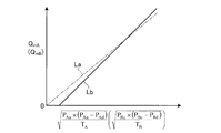
- FIG. 3 is a diagram showing the relationship between the flow rate and the pressure parameter in the first reduction catalyst.
- Linear La of one-dot chain line in FIG. 3 is a flow Q mA shown by the formula (1) (Q mB), the pressure parameter ⁇ (P Au ⁇ (P Au -P Ad) / T A) ( ⁇ (P Bu ⁇ ( P Bu -P Bd ) / T B )).
- the relationship between the two is theoretically a linear function of the slope k passing through the origin as indicated by the straight line La.
- the first catalyst 25A and the second catalyst 25B when an approximate expression is obtained from the result of actually measuring the flow rate Q mA and the pressure parameter using the least square method or the like, it is indicated by a solid line Lb in FIG. May be a linear function that does not pass through the origin. In this case, the accuracy of the first flow rate Q mA and the second flow rate Q mB is improved by using an approximate expression based on actual measurement.
- the example in which the relationship between the flow rate Q mA and the pressure parameter is a linear function is shown, but the function representing the relationship between the two is not limited to this.
- the relationship between the two may be represented by various functions such as a quadratic function, a cubic function, an n-order function (n is a real number), or an exponential function.
- the differential pressures ⁇ P A and ⁇ P B are obtained, all of the pressures P Au , P Bu , P Ad , and P Bd are measured. For this reason, even when the pressures P Au and P Bu of the exhaust gas EX on the upstream side of the first branch pipe 22A and the second branch pipe 22B are low, a decrease in accuracy of the flow rate ratio ⁇ can be suppressed.
- the pressures P Ad and P Bd of the exhaust gas EX on the downstream side of the first branch pipe 22A and the second branch pipe 22B may be regarded as atmospheric pressure, but the pressures P Ad and P Bd are actually measured as in this example. By doing so, a change in atmospheric pressure can be reflected in the flow rate ratio ⁇ . As a result, the accuracy of the flow rate ratio ⁇ can be improved.
- the flow rate ratio ⁇ is an output of the processing unit 51.
- the pressures P Ad and P Bd on the downstream side of the first catalyst 25A and the second catalyst 25B may be atmospheric pressure.
- the atmospheric pressure may be handled as constant, or the detection value of the atmospheric pressure sensor used for controlling the diesel engine 10 or the like may be used. In this way, there is an advantage that the processing can be simplified as compared with the case where the pressures P Ad and P Bd are actually measured.
- the control device 50 determines the first catalyst 25A and the second catalyst based on the detection values of the first temperature sensor 28A and the second temperature sensor 28B shown in FIG. The temperatures T A and T B of the exhaust gas EX on the upstream side of 25B are obtained. Further, as described above, the control device 50, the temperature of the exhaust gas EX estimated from the operating conditions such as load and rotational speed of the diesel engine 10, the temperature estimated value obtained T A, may be T B.
- one pressure sensor by disposing one pressure sensor on the upstream side of each NOx reduction catalyst, the flow rate of the exhaust gas EX flowing through each NOx reduction catalyst can be obtained. For this reason, the structure of the exhaust gas treatment apparatus 20 can be simplified, and the manufacturing cost can be reduced.
- one pressure sensor may be further arranged on the downstream side of each NOx reduction catalyst. In this way, the flow rate of the exhaust gas EX flowing through each NOx reduction catalyst can be obtained more accurately.
- the total flow rate Q m of the exhaust gas EX is obtained from the intake air amount M Ar of the diesel engine 10 and the fuel injection amount M Fl of the diesel engine 10. These are information that must be used for the control of the diesel engine 10 during operation. Therefore, by using these, it is possible to determine the total flow rate Q m of the exhaust gas EX relatively easily. Moreover, since the existing information is used, it can be easily applied to various diesel engines 10 and exhaust gas treatment devices 20 thereof, and there is an advantage that versatility is high.
- a filter may be provided on the upstream side of each NOx reduction catalyst, and each pressure sensor may be disposed between each filter and each NOx reduction catalyst.
- the number is not limited to two and may be three or more.
- the flow rate Q mi of the exhaust gas EX flowing through each NOx reduction catalyst is expressed by the equations (14) and (15).
- i is a subscript for identifying the plurality of exhaust gas passages and the NOx reduction catalyst, and is an integer of 1 or more.
- P ui is the pressure of the exhaust gas EX on the upstream side of the NOx reduction catalyst
- P di is the pressure of the exhaust gas EX on the downstream side of the NOx reduction catalyst
- T i is the temperature of the exhaust gas EX on the upstream side of the NOx reduction catalyst.
- D1 i and D2 i are constants.
- the fuel injection amount M Fl used when obtaining the total flow rate Q m of the exhaust gas EX the sum of the fuel injection amounts in the respective cylinder rows may be used.
- the flow rate of the exhaust gas EX flowing through each exhaust gas passage is obtained based on the pressure in each exhaust gas passage.
- the present embodiment can be applied to a diesel engine having a plurality of exhaust gas passages through which the exhaust gas EX passes, and in which the NOx reduction catalyst is provided in each exhaust gas passage.
Landscapes
- Engineering & Computer Science (AREA)
- Chemical & Material Sciences (AREA)
- Combustion & Propulsion (AREA)
- General Engineering & Computer Science (AREA)
- Mechanical Engineering (AREA)
- Chemical Kinetics & Catalysis (AREA)
- Health & Medical Sciences (AREA)
- Environmental & Geological Engineering (AREA)
- Biomedical Technology (AREA)
- Analytical Chemistry (AREA)
- General Chemical & Material Sciences (AREA)
- Oil, Petroleum & Natural Gas (AREA)
- Toxicology (AREA)
- Exhaust Gas After Treatment (AREA)
- Processes For Solid Components From Exhaust (AREA)
Description
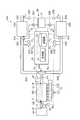
図1は、本実施形態に係る排ガス処理装置を備えるディーゼルエンジンを示す概略図である。ディーゼルエンジン10は、排ガス処理装置20を備える。排ガス処理装置20については後述する。ディーゼルエンジン10及び排ガス処理装置20は、制御装置50によって制御される。ディーゼルエンジン10は、燃料噴射装置11と、吸気通路としての吸気管12とを備える。また、排ガス処理装置20が備える排ガス導入通路としての排気管21がディーゼルエンジン10の排気口16に取り付けられる。
排ガス処理装置20は、ディーゼルエンジン10から排出された排ガスEXを浄化する装置であり、主として、排ガスEXに含まれるNOx(窒素酸化物)を低減させる。本実施形態において、排ガス処理装置20は、複数の排ガス通路としての第1分岐管22A及び第2分岐管22Bと、NOx検出センサ15と、NOxを還元する還元触媒(以下、適宜NOx還元触媒という)としての第1触媒25A及び第2触媒25Bと、圧力センサとしての第1圧力センサ27A及び第2圧力センサ27Bと、前述した制御装置50と、を含む。本実施形態において、前述した排気管21も排ガス処理装置20に含まれるが、排気管21は排ガス処理装置20にとって必須ではない。
図2は、本実施形態の変形例に係る排ガス処理装置を備えるディーゼルエンジンを示す概略図である。図2に示す排ガス処理装置20Aは、図1に示す排ガス処理装置20が備える第1DPF23A及び第2DPF23Bを備えていない。このように、第1DPF23A及び第2DPF23Bが省略されていてもよく、必要に応じて適宜用いることができる。また、第1温度センサ28A、第2温度センサ28B、第3圧力センサ29A及び第4圧力センサ29Bは、必ずしも排ガス処理装置20Aに必要ではない。第1温度センサ28A及び第2温度センサ28B又は第3圧力センサ29A及び第4圧力センサ29Bは、必要に応じて、適宜排ガス処理装置20Aに備えられていればよい。
本実施形態に係る排ガス処理方法は、少なくとも、排ガス処理装置20が備えるNOx検出センサ15、第1圧力センサ27A及び第2圧力センサ27Bを用いることによって実現できる。排ガス処理装置20が備える第1触媒25Aと第2触媒25Bとは、それぞれ第1分岐管22Aと第2分岐管22Bとの抵抗体と見なすことができる。







本実施形態に係る排ガス処理方法の第2例は、前述した第1例と同様であるが、第1触媒25Aと第2触媒25Bとの上流側における第1分岐管22Aと第2分岐管22Bとの圧力に基づいて第1流量QmAと第2流量QmBとの比である流量比QmA/QmBと、ディーゼルエンジン10が排出した排ガスEXの総流量とを用いる点が異なる。


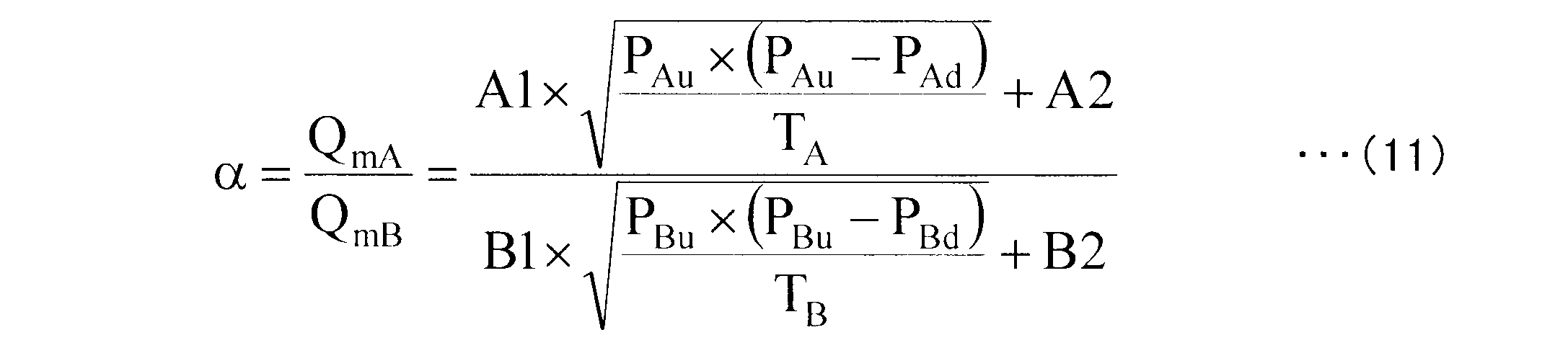


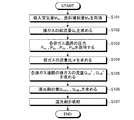
図4は、本実施形態に係る排ガス処理方法の処理フロー図である。次の説明において、流体の流量、すなわち吸入空気量及び排ガスEXの流量等は、いずれも質量流量である。本実施形態に係る排ガス処理方法を実行するにあたり、ステップS101において、図1に示す制御装置50は、吸入空気量センサ14の検出値、すなわち、ディーゼルエンジン10の吸入空気量MArと燃料噴射装置11の燃料噴射量MFlとを取得する。制御装置50は、ディーゼルエンジン10を制御する際に、運転条件に応じた燃料噴射量MFlを算出しているので、ステップS101において、制御装置50は、この算出結果を取得する。吸入空気量MAr及び燃料噴射量MFlは、制御装置50の処理部51(図1参照)への入力となる。



10C シリンダ
11 燃料噴射装置
11I インジェクタ
11R 蓄圧室
12 吸気管
13 エアクリーナ
14 吸入空気量センサ
15 NOx検出センサ
20、20a 排ガス処理装置
21 排気管
21S 分岐部
22A 第1分岐管
22B 第2分岐管
23A 第1DPF
23B 第2DPF
25A 第1触媒
25B 第2触媒
27A 第1圧力センサ
27B 第2圧力センサ
28A 第1温度センサ
28B 第2温度センサ
29A 第3圧力センサ
29B 第4圧力センサ
30 還元剤供給装置
50 制御装置
51 処理部
52 記憶部
R 還元剤
α、εi 流量比
Claims (10)
- ディーゼルエンジンが排出した排ガスを複数に分岐させて通過させる複数の排ガス通路と、
それぞれの前記排ガス通路に設けられて、還元剤によって排ガス中のNOxを還元する還元触媒と、
前記触媒よりも排ガスの流れ方向における上流側に配置されて、前記ディーゼルエンジンが排出した排ガスに含まれるNOxの濃度を検出するNOx検出センサと、
それぞれの前記還元触媒の、排ガスの流れ方向における上流側に配置されてそれぞれの前記排ガス通路内の圧力を検出する圧力センサと、
少なくともそれぞれの前記圧力センサの検出値に基づいてそれぞれの前記排ガス通路を流れる排ガスの流量を求め、得られたそれぞれの前記排ガス通路における排ガスの流量及び前記NOx検出センサが検出したNOxの濃度からそれぞれの前記排ガス通路におけるNOxの流量を求め、得られたそれぞれの前記排ガス通路におけるNOxの流量からそれぞれの前記還元触媒に供給する還元剤の量を求める制御装置と、
を含む排ガス処理装置。 - 前記ディーゼルエンジンが排出した排ガスの総流量を求める排ガス総流量検出部を有し、
前記制御装置は、それぞれの前記圧力センサの検出値に基づき、それぞれの前記排ガス通路を流れる排ガスの流量比を求め、得られた前記流量比及び排ガスの前記総流量に基づいてそれぞれの前記排ガス通路を流れる排ガスの流量を求める、請求項1に記載の排ガス処理装置。 - 前記制御装置は、前記ディーゼルエンジンの吸入空気量と前記ディーゼルエンジンに対する燃料噴射量とから排ガスの前記総流量を求める、請求項2に記載の排ガス処理装置。
- それぞれの前記排ガス通路を流れる排ガスの温度を検出する温度センサを備え、
前記制御装置は、前記温度センサが検出した排ガスの温度をさらに用いて、前記排ガス通路を流れる排ガスの流量を求める、請求項1から請求項3のいずれか1項に記載の排ガス処理装置。 - それぞれの前記還元触媒の、排ガスの流れ方向における上流側にそれぞれフィルタが設けられ、
それぞれの前記圧力センサは、それぞれの前記フィルタと前記還元触媒との間に配置される、請求項1から請求項4のいずれか1項に記載の排ガス処理装置。 - 請求項1から請求項5のいずれか1項に記載の排ガス処理装置を備える、ディーゼルエンジン。
- ディーゼルエンジンが排出した排ガスを複数の排ガス通路に分岐させて複数のNOxを還元する還元触媒に導き、還元剤及び前記還元触媒によって前記排ガス中のNOxを還元するにあたり、
それぞれの前記還元触媒の、排ガスの流れ方向における上流側における前記排ガス通路内の圧力に少なくとも基づいて、それぞれの前記排ガス通路を流れる排ガスの流量を求める手順と、
得られたそれぞれの前記排ガス通路における排ガスの流量及び前記還元触媒よりも前記排ガスの流れ方向における上流側の排ガスに含まれる前記NOxの濃度からそれぞれの前記排ガス通路におけるNOxの流量を求める手順と、
得られたそれぞれの前記排ガス通路におけるNOxの流量からそれぞれの前記還元触媒に与える還元剤の量を求める手順と、
を含む排ガス処理方法。 - それぞれの前記排ガス通路を流れる排ガスの流量を求める手順において、
それぞれの前記排ガス通路内の圧力に基づき、それぞれの前記排ガス通路を流れる排ガスの流量比を求め、得られた前記流量比及び排ガスの総流量に基づいてそれぞれの前記排ガス通路を流れる排ガスの流量を求める、請求項7に記載の排ガス処理方法。 - 前記ディーゼルエンジンの吸入空気量と前記ディーゼルエンジンに対する燃料噴射量とから排ガスの前記総流量を求める、請求項8に記載の排ガス処理方法。
- それぞれの前記排ガス通路を流れる排ガスの流量を求める手順において、
それぞれの前記排ガス通路を流れる排ガスの温度をさらに用いて、前記排ガス通路を流れる排ガスの流量を求める、請求項7から請求項9のいずれか1項に記載の排ガス処理方法。
Priority Applications (3)
| Application Number | Priority Date | Filing Date | Title |
|---|---|---|---|
| US14/427,445 US9539546B2 (en) | 2012-09-13 | 2013-07-24 | Exhaust gas processing device, diesel engine, and exhaust gas processing method |
| DE112013004471.4T DE112013004471B4 (de) | 2012-09-13 | 2013-07-24 | Abgasbehandlungsverfahren |
| CN201380046146.3A CN104603411B (zh) | 2012-09-13 | 2013-07-24 | 废气处理装置、柴油发动机以及废气处理方法 |
Applications Claiming Priority (2)
| Application Number | Priority Date | Filing Date | Title |
|---|---|---|---|
| JP2012201881A JP5908814B2 (ja) | 2012-09-13 | 2012-09-13 | 排ガス処理装置、ディーゼルエンジン及び排ガス処理方法 |
| JP2012-201881 | 2012-09-13 |
Publications (1)
| Publication Number | Publication Date |
|---|---|
| WO2014041899A1 true WO2014041899A1 (ja) | 2014-03-20 |
Family
ID=50278028
Family Applications (1)
| Application Number | Title | Priority Date | Filing Date |
|---|---|---|---|
| PCT/JP2013/070089 Ceased WO2014041899A1 (ja) | 2012-09-13 | 2013-07-24 | 排ガス処理装置、ディーゼルエンジン及び排ガス処理方法 |
Country Status (5)
| Country | Link |
|---|---|
| US (1) | US9539546B2 (ja) |
| JP (1) | JP5908814B2 (ja) |
| CN (1) | CN104603411B (ja) |
| DE (1) | DE112013004471B4 (ja) |
| WO (1) | WO2014041899A1 (ja) |
Cited By (1)
| Publication number | Priority date | Publication date | Assignee | Title |
|---|---|---|---|---|
| EP2955351A1 (en) * | 2014-06-12 | 2015-12-16 | Toyota Jidosha Kabushiki Kaisha | Filling of an urea water supply system |
Families Citing this family (11)
| Publication number | Priority date | Publication date | Assignee | Title |
|---|---|---|---|---|
| DE112014006732B4 (de) * | 2014-06-11 | 2025-07-17 | Tenneco Automotive Operating Company Inc. | Abgasnachbehandlungssystem |
| WO2016078538A1 (zh) | 2014-11-21 | 2016-05-26 | 天纳克(苏州)排放系统有限公司 | 共轨组件、尿素喷射系统及其应用 |
| CN105673154B (zh) | 2014-11-21 | 2019-11-08 | 天纳克(苏州)排放系统有限公司 | 共轨、该共轨的应用、尿素喷射系统及其控制方法 |
| US9528418B2 (en) * | 2015-01-15 | 2016-12-27 | Cummins Emission Solutions, Inc. | Single sensor monitoring system for multiple after-treatment systems on engines |
| SE541017C2 (en) * | 2015-02-17 | 2019-03-05 | Scania Cv Ab | A method and a system for determining a flow resistance across a particulate filter |
| KR102301917B1 (ko) * | 2015-04-21 | 2021-09-14 | 두산인프라코어 주식회사 | 환원제 공급 제어 시스템을 포함한 동력 장치 및 환원제 공급 제어 방법 |
| US10190470B2 (en) * | 2015-06-15 | 2019-01-29 | Deere & Company | Catalytic device detection system |
| EP3995677B1 (en) * | 2020-11-06 | 2025-11-12 | Kabushiki Kaisha Toyota Chuo Kenkyusho | Control device of after-treatment system, after-treatment system, method of controlling after-treatment system, and computer program |
| KR102431125B1 (ko) * | 2021-10-14 | 2022-08-11 | 박정봉 | 질소산화물 저감시스템 및 그의 제어 방법 |
| CN116291808A (zh) * | 2023-03-06 | 2023-06-23 | 上海创怡环境技术有限公司 | 一种scr装置及控制方法 |
| CN116341764B (zh) * | 2023-05-24 | 2023-09-26 | 中国石油大学(华东) | 基于历史数据的成品油管道混油浓度分布预测方法及系统 |
Citations (6)
| Publication number | Priority date | Publication date | Assignee | Title |
|---|---|---|---|---|
| JP2006233893A (ja) * | 2005-02-25 | 2006-09-07 | Toyota Motor Corp | 内燃機関の排気浄化装置 |
| JP3905264B2 (ja) * | 1999-10-14 | 2007-04-18 | 日野自動車株式会社 | エンジンの排ガス浄化装置 |
| JP4131667B2 (ja) * | 2001-01-08 | 2008-08-13 | ローベルト ボツシユ ゲゼルシヤフト ミツト ベシユレンクテル ハフツング | 排気ガス後処理システムの制御方法および装置 |
| JP4351091B2 (ja) * | 2004-03-09 | 2009-10-28 | 寛 松岡 | 排気ガス浄化システム |
| JP2011089479A (ja) * | 2009-10-22 | 2011-05-06 | Mitsubishi Fuso Truck & Bus Corp | Dpf再生制御装置 |
| WO2011118525A1 (ja) * | 2010-03-25 | 2011-09-29 | Udトラックス株式会社 | エンジンの排気浄化装置 |
Family Cites Families (9)
| Publication number | Priority date | Publication date | Assignee | Title |
|---|---|---|---|---|
| JP4148231B2 (ja) * | 2005-03-09 | 2008-09-10 | トヨタ自動車株式会社 | 内燃機関の排気浄化システム |
| FR2929399B1 (fr) | 2008-03-28 | 2010-04-30 | Centre Nat Rech Scient | Debimetre instationnaire temps reel |
| DE102009015419A1 (de) | 2009-03-27 | 2010-09-30 | Emitec Gesellschaft Für Emissionstechnologie Mbh | Verfahren zur Zufuhr von Reduktionsmittel in ein Abgassystem und entsprechendes Abgassystem |
| DE102009016810A1 (de) | 2009-04-09 | 2010-10-14 | Albonair Gmbh | Dosiersystem zur Eindüsung eines Reduktionsmittels in den Abgasstrom eines Verbrennungsmotors |
| WO2012051273A1 (en) | 2010-10-13 | 2012-04-19 | Cummins Intellectual Property, Inc. | Multi-leg exhaust aftertreatment system and method |
| WO2012078325A1 (en) * | 2010-12-07 | 2012-06-14 | Cummins Intellectual Property, Inc. | Multi-leg exhaust after-treatment system and method |
| US20120210700A1 (en) * | 2011-02-17 | 2012-08-23 | Detroit Diesel Corporation | Method to monitor pressure drop across a selective catalyst reducer for engine and exhaust airflow diagnostics |
| DE112013004414B4 (de) * | 2013-07-18 | 2016-12-29 | Komatsu Ltd. | Abgasbehandlungsvorrichtung, Dieselmaschine und Abgasbehandlungsverfahren |
| DE102014004439B4 (de) * | 2014-03-27 | 2026-03-19 | Daimler Truck AG | Verfahren zum Betreiben eines an eine Kraftfahrzeugbrennkraftmaschine angeschlossenen Abgasreinigungssystems umfassend einen SCR-Katalysator |
-
2012
- 2012-09-13 JP JP2012201881A patent/JP5908814B2/ja not_active Expired - Fee Related
-
2013
- 2013-07-24 WO PCT/JP2013/070089 patent/WO2014041899A1/ja not_active Ceased
- 2013-07-24 US US14/427,445 patent/US9539546B2/en not_active Expired - Fee Related
- 2013-07-24 DE DE112013004471.4T patent/DE112013004471B4/de not_active Expired - Fee Related
- 2013-07-24 CN CN201380046146.3A patent/CN104603411B/zh not_active Expired - Fee Related
Patent Citations (6)
| Publication number | Priority date | Publication date | Assignee | Title |
|---|---|---|---|---|
| JP3905264B2 (ja) * | 1999-10-14 | 2007-04-18 | 日野自動車株式会社 | エンジンの排ガス浄化装置 |
| JP4131667B2 (ja) * | 2001-01-08 | 2008-08-13 | ローベルト ボツシユ ゲゼルシヤフト ミツト ベシユレンクテル ハフツング | 排気ガス後処理システムの制御方法および装置 |
| JP4351091B2 (ja) * | 2004-03-09 | 2009-10-28 | 寛 松岡 | 排気ガス浄化システム |
| JP2006233893A (ja) * | 2005-02-25 | 2006-09-07 | Toyota Motor Corp | 内燃機関の排気浄化装置 |
| JP2011089479A (ja) * | 2009-10-22 | 2011-05-06 | Mitsubishi Fuso Truck & Bus Corp | Dpf再生制御装置 |
| WO2011118525A1 (ja) * | 2010-03-25 | 2011-09-29 | Udトラックス株式会社 | エンジンの排気浄化装置 |
Cited By (1)
| Publication number | Priority date | Publication date | Assignee | Title |
|---|---|---|---|---|
| EP2955351A1 (en) * | 2014-06-12 | 2015-12-16 | Toyota Jidosha Kabushiki Kaisha | Filling of an urea water supply system |
Also Published As
| Publication number | Publication date |
|---|---|
| JP2014055566A (ja) | 2014-03-27 |
| CN104603411A (zh) | 2015-05-06 |
| DE112013004471T5 (de) | 2015-06-25 |
| US20150224447A1 (en) | 2015-08-13 |
| DE112013004471B4 (de) | 2021-09-09 |
| CN104603411B (zh) | 2017-04-12 |
| US9539546B2 (en) | 2017-01-10 |
| JP5908814B2 (ja) | 2016-04-26 |
Similar Documents
| Publication | Publication Date | Title |
|---|---|---|
| JP5908814B2 (ja) | 排ガス処理装置、ディーゼルエンジン及び排ガス処理方法 | |
| JP5753325B2 (ja) | 排ガス処理装置、ディーゼルエンジン及び排ガス処理方法 | |
| US9702293B2 (en) | Diagnostic device | |
| CN111263848B (zh) | 用于操作柴油发动机的废气后处理系统的方法和废气后处理系统 | |
| US12012880B2 (en) | System and methods for controlling flow distribution in an aftertreatment system | |
| CN111801489B (zh) | 使用双压差传感器改善的烟灰负载估计 | |
| WO2012078325A1 (en) | Multi-leg exhaust after-treatment system and method | |
| US10436089B2 (en) | Radio frequency sensor in an exhaust aftertreatment system | |
| JP6163996B2 (ja) | 診断装置 | |
| US11795848B2 (en) | Systems and methods for controlling exhaust gas aftertreatment sensor systems | |
| CN111810279A (zh) | 用于求取氨质量流的方法 | |
| KR102342938B1 (ko) | 디젤 미립자 필터를 포함하는 디젤 엔진 및 디젤 엔진을 작동시키기 위한 방법 | |
| US9885273B2 (en) | Diagnostic device for an oxidation catalyst | |
| CN107269368A (zh) | 用于监视甲烷氧化催化器的方法和废气后处理装置 | |
| CN118190434B (zh) | Doc对发动机排气污染物转化效率的验证方法及发动机台架 | |
| JP6191355B2 (ja) | 診断装置 | |
| JP2015055167A (ja) | 排気浄化装置 | |
| BR112020017863B1 (pt) | Método para estimar a carga de fuligem e sistema de filtragem de escape de um sistema de pós-tratamento de escape |
Legal Events
| Date | Code | Title | Description |
|---|---|---|---|
| 121 | Ep: the epo has been informed by wipo that ep was designated in this application |
Ref document number: 13836990 Country of ref document: EP Kind code of ref document: A1 |
|
| WWE | Wipo information: entry into national phase |
Ref document number: 14427445 Country of ref document: US |
|
| WWE | Wipo information: entry into national phase |
Ref document number: 1120130044714 Country of ref document: DE Ref document number: 112013004471 Country of ref document: DE |
|
| 122 | Ep: pct application non-entry in european phase |
Ref document number: 13836990 Country of ref document: EP Kind code of ref document: A1 |