WO2014041689A1 - ヘッドアップディスプレイ - Google Patents
ヘッドアップディスプレイ Download PDFInfo
- Publication number
- WO2014041689A1 WO2014041689A1 PCT/JP2012/073690 JP2012073690W WO2014041689A1 WO 2014041689 A1 WO2014041689 A1 WO 2014041689A1 JP 2012073690 W JP2012073690 W JP 2012073690W WO 2014041689 A1 WO2014041689 A1 WO 2014041689A1
- Authority
- WO
- WIPO (PCT)
- Prior art keywords
- light
- combiner
- optical element
- light source
- half mirror
- Prior art date
Links
Images


Classifications
-
- G—PHYSICS
- G02—OPTICS
- G02B—OPTICAL ELEMENTS, SYSTEMS OR APPARATUS
- G02B3/00—Simple or compound lenses
- G02B3/02—Simple or compound lenses with non-spherical faces
- G02B3/08—Simple or compound lenses with non-spherical faces with discontinuous faces, e.g. Fresnel lens
-
- G—PHYSICS
- G02—OPTICS
- G02B—OPTICAL ELEMENTS, SYSTEMS OR APPARATUS
- G02B27/00—Optical systems or apparatus not provided for by any of the groups G02B1/00 - G02B26/00, G02B30/00
- G02B27/01—Head-up displays
- G02B27/0101—Head-up displays characterised by optical features
-
- G—PHYSICS
- G02—OPTICS
- G02B—OPTICAL ELEMENTS, SYSTEMS OR APPARATUS
- G02B27/00—Optical systems or apparatus not provided for by any of the groups G02B1/00 - G02B26/00, G02B30/00
- G02B27/01—Head-up displays
- G02B27/0101—Head-up displays characterised by optical features
- G02B2027/0123—Head-up displays characterised by optical features comprising devices increasing the field of view
Definitions
- the present invention relates to a technical field for visually recognizing an image as a virtual image.
- a head-up display for visually recognizing an image as a virtual image
- a half mirror called a combiner (synthesizer) is used to make a driver visually recognize a small screen (real image) such as a small liquid crystal display as an enlarged virtual image.
- a combiner using a Fresnel structure.
- a virtual image observable region (hereinafter referred to as an “eye box”) formed by the combiner.
- the installation angle of the combiner necessary for forming near the head is automatically determined. For example, when the light constituting the real image is incident on the combiner installed in front of the driver from above, the installation angle of the combiner is inclined in the direction opposite to the inclination of the windshield. In this case, the eyebox is formed at an appropriate position (near the driver's head), but the presence of the combiner is large, which may give the driver a feeling of pressure or discomfort.
- the combiner is tilted in the same direction as the windshield, the feeling of pressure and discomfort to the combiner is considerably reduced, but the eyebox is not formed at an appropriate position (for example, an eyebox is formed on the abdomen of the driver). ), The driver will not be able to see the virtual image.
- An object of the present invention is to appropriately form an eye box in a head-up display having an optical element having a Fresnel structure without giving a viewer a feeling of pressure or discomfort.
- the light source part that emits light constituting the display image and the light from the light source part are incident from above and arranged in the same direction as the inclination direction of the windshield of the moving body.
- the half mirror reflects the light from the light source unit by the half mirror, and the half mirror has a Fresnel structure in which the center of the free curved surface that is the basis of the Fresnel structure is not located at the center of the half mirror.
- the relative position between the light source unit and the optical element so that the light reflected by the half mirror is emitted outside the optical element without being totally reflected. Characterized in that it is set.
- the figure which showed the general head-up display roughly The figure for demonstrating the relationship between the installation angle of a combiner and the position of an eyebox is shown.
- the figure for demonstrating the basic concept of a present Example is shown.
- the figure for demonstrating that a malfunction can be solved by using the combiner to which the offset Fresnel structure was applied is shown.
- the figure for demonstrating the subject 1 concretely is shown.
- the figure for demonstrating the subject 2 concretely concretely is shown.
- the figure for demonstrating the conditions of the incident angle for making an emission angle less than a total reflection angle is shown.
- positioning example of the combiner which concerns on 1st Example is shown.
- positioning example of the combiner which concerns on 2nd Example is shown.
- a light source unit that emits light constituting a display image
- an optical device in which light from the light source unit is incident from above and arranged in the same direction as the tilt direction of the windshield of the moving body
- a head-up display that visually recognizes the display image as a virtual image by reflecting light constituting the display image with the optical element, the optical element having a Fresnel structure in one flat plate.
- a half mirror is formed, the light from the light source unit is reflected by the half mirror, and the half mirror is applied with a Fresnel structure in which the center of the free curved surface that is the basis of the Fresnel structure is not located at the center of the half mirror
- the relative position between the light source unit and the optical element is such that the light reflected by the half mirror is emitted outside the optical element without being totally reflected. It is constant.
- the head-up display is installed on a moving body and is used to visually recognize the display image as a virtual image by reflecting light constituting the display image emitted from the light source unit with an optical element (for example, a combiner).
- the optical element receives light from the light source unit from above and is arranged in the same direction as the inclination direction of the windshield of the moving body.
- a Fresnel half mirror is formed in one flat plate, and the light from the light source unit is reflected by the half mirror.
- the half mirror employs a Fresnel structure in which the center (for example, the vertex) of the free curved surface that is the basis of the Fresnel structure is not located at the center of the half mirror.
- the relative position between the light source unit and the optical element is set so that the light reflected by the half mirror is emitted outside the optical element without being totally reflected inside the optical element.
- the light from the light source unit enters the optical element at an incident angle such that the light reflected by the half mirror is emitted outside without being totally reflected.
- the optical element on which light from the light source unit is incident from above is windshielded.
- the eye box can be appropriately formed in the vicinity of the observer's head. Therefore, the eyebox can be formed at an appropriate position without giving the observer a feeling of pressure or discomfort.
- the relative position between the light source unit and the optical element is set so that the light reflected by the half mirror is emitted to the outside without being totally reflected. It is possible to appropriately emit light, and it is possible to appropriately avoid a problem that a part of the virtual image cannot be visually recognized. Therefore, the entire surface of the optical element can be used effectively.
- an incident angle at which light from the light source unit enters the optical element is “ ⁇ in ”, and a refractive index of a substrate provided outside the half mirror in the optical element is If the focal length of the free-form surface is “f”, and the distance between the position where the light from the light source is incident on the half mirror and the center of the free-form surface is “OFS”, the incident angle is “n”.
- the relative position between the light source unit and the optical element is set so that ⁇ in satisfies the following condition.
- ⁇ in > sin ⁇ 1 [n ⁇ sin ⁇ 2 tan ⁇ 1 (OFS / 2f) ⁇ sin ⁇ 1 (1 / n) ⁇ ]
- light from the light source unit is incident on the optical element such that the amount of change in transmittance of the substrate provided outside the half mirror is a predetermined value or less.
- a relative position between the light source unit and the optical element is set so that an incident angle range is used.
- the relative position between the light source unit and the optical element is set so that a region where the transmittance of the substrate is less dependent on the incident angle is used.
- the light source unit emits P-polarized light.
- substrate can be made small compared with the case where S polarized light is used.
- the light source unit includes an exit pupil enlarging element that expands an exit pupil of light emitted from the light source, and uses the light from the exit pupil enlarging element as the optical element. It emits toward.
- an LCD or CRT In the case of using an LCD or CRT, light diffuses at a large angle.
- an exit pupil enlarging element it is possible to easily realize a narrow control of the diffusion angle.
- FIG. 1 is a diagram schematically showing a general head-up display.
- a screen to be displayed (real image RI) is formed, and the light constituting the real image RI is reflected by the combiner 10, thereby allowing the driver to visually recognize the virtual image VI corresponding to the real image RI.
- the real image RI corresponds to a screen displayed by a small liquid crystal display or an image formed on a screen by a projector (in one example, an image formed by an exit pupil expanding element (EPE: Exit-Pupil Expander)).
- EPE Exit-Pupil Expander
- a small liquid crystal display, a projector, and a screen correspond to an example of a “light source unit” in the present invention.
- a method of increasing the light utilization efficiency is usually used.
- the emission angle of the real image RI is limited, and the concave half-half is used as the combiner 10 so that the light reflected by the combiner 10 is collected on the observer's head.
- the focal length of the concave half mirror is set to an appropriate value using a mirror.
- a region indicated by reference numeral EB is a virtual image observable region (eye box) formed near the observer's head.
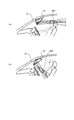
- FIG. 2 is a diagram for explaining the relationship between the installation angle of the combiner 10 and the position of the eye box EB formed by the combiner 10.
- a (concave) half mirror as shown in FIG. 1 is used as the combiner 10
- the combiner required to form the eye box EB near the driver's head Ten installation angles are automatically determined.
- FIG. 2A when the light constituting the real image RI is incident on the combiner 10 installed in front of the driver from above, the installation angle of the combiner 10 is opposite to the inclination of the windshield. Will tilt in the direction.
- the eye box EB1 is formed at an appropriate position (near the driver's head), but the presence of the combiner 10 is large, which may give the driver a feeling of pressure or discomfort. Therefore, as shown in FIG. 2B, when the combiner 10 is tilted in the same direction as the windshield, the feeling of pressure and discomfort to the combiner 10 is considerably reduced, but the eye box EB2 is formed on the abdomen of the driver. Therefore, the driver cannot visually recognize the virtual image VI.
- Patent Documents 1 and 2 disclose a combiner using a Fresnel structure.
- Patent Document 2 discloses that the optical axis of the first Fresnel lens on the first main surface provided with the first Fresnel lens is arranged at a position different from the center of the outer shape of the first main surface.
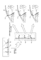
- FIG. 3 shows a diagram for explaining the basic concept of the present embodiment.
- FIG. 3 shows an example of three combiners 10x1, 10x2, and 10x3 (hereinafter, simply referred to as “combiner 10x” when they are not distinguished from each other).
- the figure and sectional drawing side view
- the front view and sectional drawing have shown the image figure shown schematically.
- the combiner 10x is applied to a head-up display instead of the combiner 10 shown in FIG. 1 (the same applies to the combiners 10a and 10b described later).
- the combiner 10x has a Fresnel half mirror inside. Specifically, the combiner 10x has a plurality of minute reflecting surfaces (mirror surfaces) S2 corresponding to the curvature of the virtual paraboloid S1 that is the basis of the Fresnel structure (Fresnel pattern). Function as.
- the plurality of reflecting surfaces have a shape in which, for example, lenses having a virtual paraboloidal surface S1 are divided and arranged at equal intervals in the vertical direction in FIG.
- the combiner 10x has two members having the same refractive index on which irregularities corresponding to the curvature of the virtual paraboloid S1 are formed (hereinafter referred to as “substrate” as appropriate.
- the substrate is a cover layer in other words).
- Fresnel structure means a structure to which a shape similar to the surface shape of a known Fresnel lens is applied. That is, “Fresnel half mirror” means a half mirror to which a shape similar to the surface shape of a known Fresnel lens is applied.
- the combiner 10x1 has a vertex P2 of the virtual paraboloid S1 (in other words, the center of the virtual paraboloid S1, the same shall apply hereinafter) at the center (outline center). That is, the combiner 10x1 has a Fresnel structure based on the virtual paraboloid S1 in which the vertex P2 is located at the center point P3x1 on the surface of the half mirror. Therefore, in the combiner 10x1, the inclination of the reflecting surface S2 formed inside is small. On the other hand, the vertexes P2 of the virtual paraboloid S1 are not located at the centers (outer shape centers) of the combiners 10x2 and 10x3.
- the combiner 10x2, 10x3 has a Fresnel structure based on the virtual paraboloid S1 in which the vertex P2 is located at a location deviating from the center points P3x2, P3x3 on the surface of the half mirror.
- the combiner 10x2, 10x3 is applied with a region off the center of the Fresnel pattern. Therefore, in combiner 10x2, 10x3, the inclination of reflective surface S2 formed inside is large (that is, reflective surface S2 stands).
- offset amount is an amount by which the vertex P2 of the virtual paraboloid S1 is shifted from the center points P3x2 and P3x3 of the half mirror (in other words, the distance between the vertex P2 and the center points P3x2 and P3x3). expressed. In the example shown in FIG.
- the combiner 10x2 has a Fresnel structure based on a virtual paraboloid S1 in which the vertex P2 is shifted from the center point P3x2 of the half mirror by an offset amount OFSx2, and the combiner 10x3 is a half A Fresnel structure based on a virtual paraboloid S1 in which the vertex P2 is shifted by the offset amount OFSx3 from the mirror center point P3x3 is applied.
- a paraboloid as a base surface of the Fresnel structure.
- a spherical shape may be used, or an aspherical shape may be used to correct aberration.
- various free-form surfaces for example, curved surfaces with a focal point defined
- the characteristics of the half mirror including the substrate (cover layer) covering the reflecting surface are in accordance with the paraboloid (that is, when light is incident on the combiner vertically)
- a non-parabolic surface can be applied as the basis of the Fresnel structure (so that light reflected from the reflecting surface and transmitted through the substrate is emitted toward the focal point of the parabolic surface).
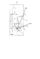
- FIG. 4 shows that by using the combiner to which the offset Fresnel structure as described above is applied, the eyebox EB can be appropriately formed near the driver's head even if the combiner is tilted in the same direction as the windshield. Will be described.
- FIG. 4 shows a state in which the combiner 10x1, 10x2, 10x3 shown in FIG. 3 is installed in the vehicle in a state where the angle of the reflected light is rotated horizontally after being rotated 90 ° clockwise. . From FIG.
- the eyebox EB can be attached to the driver's head even if the combiner 10x3 is inclined in the same direction as the windshield. It can be seen that it can be properly formed in the vicinity. That is, the problem as shown in FIG. 2B (the problem that the combiner 10 tilted in the same direction as the windshield causes the eye box EB2 of the real image RI installed near the ceiling to be formed in the abdomen) is solved. I can say that.
- the combiner 10x to which the Fresnel structure as described above is applied differs from the general combiner 10 as shown in FIG. 1 in that the reflecting surface S2 is not in the surface but in the substrate, so there are some problems. (Problems 1 and 2) may occur.
- the problem 1 is a problem that the light reflected by the reflection surface S2 inside the substrate in the combiner 10x may not be emitted from the substrate (cover layer) due to total reflection.
- the problem 2 is a problem that the amount of light reaching the observer is changed between the upper part and the lower part of the combiner 10x. Such problems 1 and 2 will be specifically described with reference to FIGS. 5 and 6.
- FIG. 5 is a diagram for specifically explaining the first problem.
- FIGS. 5A and 5B illustrate light reflected by the reflecting surface S2 inside the substrate in the combiner 10x (as illustrated, the light reflected by the reflecting surface S2 is incident on the substrate). Will be different from the angle).
- FIG. 5A shows a case where a Fresnel structure with a relatively small offset amount is applied. In this case, the light reflected by the reflecting surface S2 inside the substrate is emitted from the inside of the substrate to the outside.
- FIG. 5B shows a case where a Fresnel structure having a relatively large offset amount is applied.
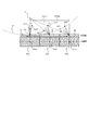
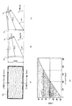
- FIG. 6 is a diagram for specifically explaining the problem 2.
- FIG. 6A shows a case where the real image RI is installed on the upper part of the combiner 10x in a state where the combiner 10x is inclined in the same direction as the windshield. In this case, light from the real image RI is incident on the combiner 10x at a deep angle. Further, the incident angle ⁇ 1 at which light enters the lower part of the combiner 10 x is larger than the incident angle ⁇ 2 at which light enters the upper part of the combiner 10 x ( ⁇ 1 > ⁇ 2 ).
- FIG. 6B shows the relationship between the incident angle [°] and “transmittance at entrance ⁇ transmittance at exit” [%] in the combiner 10.
- “Transmittance at entrance x Transmittance at exit” corresponds to the amount of light emitted from the combiner 10x (that is, the amount of light reaching the observer).
- the symbol GRp indicates a graph when P-polarized light is used
- the symbol GRs indicates a graph when S-polarized light is used.
- Such graphs GRp and GRs use a combiner 10x in which the refractive index n of the substrate (cover layer) is 1.59, and the focal length f of the virtual paraboloid S1 is 300 [mm], and the offset amount is 250. This is a result obtained when light is incident on a position [mm] (assuming that the reflectance of the reflecting surface S2 is 100%).
- FIG. 6B shows that the value of “transmittance upon incidence ⁇ transmittance upon exit” varies depending on the incident angle to the combiner 10x. Specifically, it can be seen that in the region where the incident angle is large, the value of “transmittance upon incidence ⁇ transmittance upon exit” is greatly reduced. In addition, the value of “transmittance at incidence ⁇ transmittance at output” is generally smaller for S-polarized light than that for P-polarized light, and the value of “transmittance at incident ⁇ transmittance at output” starts to decrease. It can be seen that the incident angle is small. The reason why the value of “transmittance upon incidence ⁇ transmittance upon exit” is 0 [%] in the region where the incident angle is approximately 10 ° or less is that total reflection has occurred.
- the first embodiment is mainly intended to solve the problem 1
- the second embodiment is mainly intended to solve the problem 2.
- the combiner and the real image RI are arranged so that the light reflected by the reflecting surface in the combiner to which the Fresnel structure is applied is appropriately emitted outside the combiner without being totally reflected.
- the relative position is set. That is, in the first embodiment, the angle at which the light reflected by the reflecting surface inside the substrate in the combiner is incident on the inner surface of the substrate surface (hereinafter referred to as “emission angle” as appropriate) is less than the total reflection angle. Then, the relative position between the combiner and the real image RI is set.
- FIG. 7 shows a cross-sectional image view of the combiner 10a according to the first embodiment.
- incident light is incident on the combiner 10a at an incident angle ⁇ in and is refracted by a substrate having a refractive index n to become an angle ⁇ in ′.
- this incident light injects into the point P10 on the reflective surface S2 of the Fresnel structure inside the combiner 10a.
- the point P10 is located at a location separated from the vertex P2 of the virtual paraboloid S1 by “OFS” in the x direction (“OFS” corresponds to an offset amount).
- the light reflected at the point P10 on the reflecting surface S2 is incident on the inner surface S3 of the substrate surface at an angle “ ⁇ in '+ 2 ⁇ ”.
- This angle “ ⁇ in '+ 2 ⁇ ” corresponds to the above-described emission angle.
- the condition for setting the emission angle to be less than the total reflection angle “sin ⁇ 1 (1 / n)” is expressed by the following equation (1).
- Equation (3) the condition that the incident angle ⁇ in should satisfy is expressed by a refractive index n, an offset amount OFS, and a focal length f.
- the relative position between the combiner 10a and the real image RI is set so that the incident angle ⁇ in that satisfies the condition of Expression (3) is realized. That is, the relative position between the combiner 10a and the real image RI is set so that the light constituting the real image RI is incident on the combiner 10a at an incident angle ⁇ in that satisfies the condition of the expression (3).
- the light reflected by the reflecting surface S2 inside the substrate can be appropriately emitted to the outside, and it is possible to appropriately avoid the problem that a part of the virtual image cannot be visually recognized. Therefore, the entire surface of the combiner 10a can be used effectively.
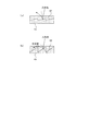
- FIG. 8 is a diagram for explaining an optimal arrangement example of the combiner 10a according to the first embodiment.
- Fig.8 (a) has shown the front image figure of the combiner 10a which concerns on 1st Example.
- the combiner 10a according to the first embodiment has the same basic configuration as the combiners 10x2, 10x3 described above. That is, in the combiner 10a according to the first embodiment, a half mirror to which the offset Fresnel structure is applied is formed inside.
- the refractive index n of the substrate (cover layer) is 1.59 (polycarbonate is used as the substrate), and the focal length f of the virtual paraboloid underlying the Fresnel structure is 300 [mm],
- the offset amount (distance between the focal point of the virtual paraboloid on which the Fresnel structure is based and the upper end portion of the combiner 10a) is 200 [mm] at the upper end, and the offset amount (of the Fresnel structure) at the lower end. It is assumed that the distance between the focal point of the original virtual paraboloid and the lower end of the combiner 10a is 350 [mm].
- the vertical size of the real image RI (display screen) is 50 [mm]
- the distance between the real image RI and the combiner 10a is 180 [mm]
- the combiner 10a is placed on the windshield side at an inclination angle of 20 °.
- FIG. 8B shows a first arrangement example of the combiner 10a
- FIG. 8C shows a second arrangement example of the combiner 10a
- 8B and 8C are side image diagrams of the combiner 10a and the real image RI.
- the incident angle at which light enters the upper end portion of the combiner 10a is ⁇ 3.3 [°]
- the incident angle at which light enters the lower end portion of the combiner 10a is +26 [°].
- the incident angle at which light enters the upper end portion of the combiner 10a is +6 [°]
- the incident angle at which light enters the lower end portion of the combiner 10a is +34.2 [°].
- the incident angle is ⁇ 3.3 [°] at the upper end of the combiner 10a
- the light reflected by the reflecting surface S2 inside the substrate is emitted to the outside.
- the incident angle is +26 [°] at the lower end of the combiner 10a (that is, less than +34.2 [°])
- the incident angle is +6 [°] (that is, ⁇ 3.3 [°] or more) at the upper end portion of the combiner 10a.
- the light reflected at S2 is emitted to the outside, and since the incident angle is +34.2 [°] at the lower end of the combiner 10a, the light reflected by the reflecting surface S2 inside the substrate is emitted to the outside. Therefore, when the position of the real image RI with respect to the position of the combiner 10a is set above the second arrangement example, the condition of the expression (3) is appropriately satisfied, and thus the light reflected by the reflection surface S2 inside the substrate is appropriately emitted. The Rukoto. Therefore, the entire surface of the combiner 10a can be used effectively.
- the second embodiment is mainly intended to solve the second problem.
- the combiner is used so that an incident angle range in which the amount of change in transmittance of the substrate in the combiner is equal to or less than a predetermined value (a value determined in advance by adaptation or the like) is used.
- a relative position with respect to the real image RI is set. That is, in the second embodiment, the relative position between the combiner and the real image RI is set so that a region where the transmittance of the substrate is less dependent on the incident angle is used.
- a luminance change luminance unevenness
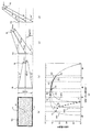
- FIG. 9 is a diagram for explaining an optimal arrangement example of the combiner 10b according to the second embodiment.
- Fig.9 (a) has shown the front image figure of the combiner 10b which concerns on 2nd Example.
- the basic structure of the combiner 10b according to the second embodiment is the same as that of the combiners 10x2, 10x3 described above. That is, in the combiner 10b according to the second embodiment, a half mirror to which the offset Fresnel structure is applied is formed inside.
- the refractive index n of the substrate (cover layer) is 1.59 (polycarbonate is used as the substrate), and the focal length f of the virtual paraboloid underlying the Fresnel structure is 300 [mm],
- the offset amount (the distance between the focal point of the virtual paraboloid on which the Fresnel structure is based and the point A) is 150 [mm] at the point A positioned at the upper end, and the offset is set at the point B positioned at the center.
- the amount (the distance between the focal point of the virtual paraboloid that is the basis of the Fresnel structure and the point B) is 200 [mm]
- the offset amount (of the virtual paraboloid that is the basis of the Fresnel structure) at the point C located at the lower end It is assumed that the distance between the focal point and the point C) is 250 [mm].
- the vertical size of the real image RI (display screen) is 36 [mm] and the distance between the real image RI and the combiner 10b is 180 [mm] will be described as an example.
- FIG. 9B shows a first arrangement example of the combiner 10b
- FIG. 9C shows a second arrangement example of the combiner 10b
- FIG. 9D shows a third arrangement of the combiner 10b.
- An arrangement example is shown.
- FIGS. 9B to 9D are side image diagrams of the combiner 10b and the real image RI.
- the incident angle at the point A of the combiner 10b is ⁇ 10 [°]
- the incident angle at the point B of the combiner 10b is 0 [°]
- the incident angle at the point C of the combiner 10b Is +10 [°].
- the incident angle at the point A of the combiner 10b is +19 [°]
- the incident angle at the point B of the combiner 10b is +30 [°]
- the incident angle at the point C of the combiner 10b is +37 [°].
- the incident angle at the point A of the combiner 10b is +52 [°]
- the incident angle at the point B of the combiner 10b is +60 [°]
- the incident angle at the point C of the combiner 10b is +64 [°].
- FIG. 9 (e) is a diagram showing the relationship between the incident angle [°] to the substrate and the transmittance of the substrate (meaning the transmittance of light reciprocating in the substrate).
- the graph GR1 shows the transmittance of the substrate for light incident on the point A of the combiner 10b
- the graph GR2 shows the transmittance of the substrate for light incident on the point B of the combiner 10b.
- the graph GR3 shows the transmittance of the substrate for the light incident on the point C of the combiner 10b.
- the graphs GR1 to GR3 are obtained based on a known calculation formula of interface reflectance (Fresnel reflectance).
- the graphs GR1 to GR3 assume the case where S-polarized light is incident on the combiner 10b.
- the incident angles at points A, B, and C of the combiner 10b are plotted on the graphs GR1, GR2, and GR3 to obtain points A1, B1, and C1, and these points A1.
- B1 and C1 are connected to obtain a broken line D1. It can be seen from the broken line D1 that when the first arrangement example is applied, the amount of change in transmittance with respect to the incident angle is large. Therefore, when the first arrangement example is applied, it can be said that the luminance change (luminance unevenness) in the plane of the combiner 10b becomes large. Therefore, in the second embodiment, such a first arrangement example is not adopted.
- the incident angles at points A, B, and C of the combiner 10b are plotted on the graphs GR1, GR2, and GR3 to obtain points A2, B2, and C2, and these points A2 , B2, and C2 are connected to obtain a broken line D2.
- the broken line D2 It can be seen from the broken line D2 that when the second arrangement example is applied, the amount of change in transmittance with respect to the incident angle is small. Therefore, when the second arrangement example is applied, it can be said that there is almost no luminance change (luminance unevenness) in the plane of the combiner 10b. Therefore, in the second embodiment, such a second arrangement example is adopted.
- the incident angles at points A, B, and C of the combiner 10b are plotted on the graphs GR1, GR2, and GR3 to obtain points A3, B3, and C3. These points A3 , B2 and C3 are connected to obtain a broken line D3. From the broken line D3, when the third arrangement example is applied, the transmittance change amount is smaller than when the first arrangement example is applied, but the transmittance change amount is smaller than when the second arrangement example is applied. You can see that it is big. Also, it can be seen that the amount of change in transmittance increases in the region on the right side of the broken line D3. Therefore, when the third arrangement example is applied, it can be said that a sharp change in brightness occurs just by slightly tilting the combiner 10b from the installation angle in the third arrangement example. Therefore, in the second embodiment, such a third arrangement example is not adopted.
- FIG. 9 illustrates the case where S-polarized light is used as the light incident on the combiner 10b
- P-polarized light may be used instead of S-polarized light.
- FIG. 6B it can be said that it is preferable to use P-polarized light rather than S-polarized light because P-polarized light has a smaller incident angle dependency of interface reflectance (transmittance) than S-polarized light.
- the second embodiment is described as the main purpose of solving the problem 2.
- the problem 1 is also solved. This is because if the problem 2 is solved, the problem 1 is inevitably solved.
- the present invention can be used for a display device such as a head-up display.
Abstract
ヘッドアップディスプレイは、表示像を構成する光を出射する光源部と、光源部からの光が上方から入射され、移動体のフロントガラスの傾斜方向と同じ方向にて配置された光学素子とを備え、表示像を構成する光を光学素子で反射することで当該表示像を虚像として視認させる。光学素子は、一の平板内に、フレネル構造のハーフミラーが形成され、当該ハーフミラーによって光源部からの光を反射する。ハーフミラーは、フレネル構造の元になる自由曲面の中心が、当該ハーフミラーの中心に位置しないフレネル構造が適用されている。ヘッドアップディスプレイでは、ハーフミラーで反射した光が全反射することなく光学素子の外部へ出射されるように、光源部と光学素子との相対位置が設定されている。
Description
本発明は、虚像として画像を視認させる技術分野に関する。
従来から、虚像として画像を視認させるヘッドアップディスプレイなどの表示装置が知られている。一般的に、ヘッドアップディスプレイでは、小型液晶ディスプレイなどの小さな画面(実像)を、拡大された虚像として運転者に視認させるために、コンバイナ(合成器)と呼ばれるハーフミラーを用いている。例えば、特許文献1及び2には、フレネル構造を利用したコンバイナが提案されている。
ところで、一般的な凹面ハーフミラーをコンバイナとして用いた場合には、実像の位置が固定されると、コンバイナによって形成される虚像観察可能領域(以下では「アイボックス」と呼ぶ。)を運転者の頭部付近に形成するのに必要なコンバイナの設置角度が自動的に決まってしまう。例えば、運転者の正面に設置されたコンバイナに対して実像を構成する光を上方から入射させる場合、コンバイナの設置角度はフロントガラスの傾斜とは逆方向に傾くことになる。この場合、アイボックスは適切な位置(運転者の頭部付近)に形成されるが、コンバイナの存在感が大きく、運転者に圧迫感や違和感を与えてしまう場合がある。そこで、コンバイナをフロントガラスと同じ方向に傾斜させると、コンバイナに対する圧迫感や違和感はかなり軽減されるが、アイボックスが適切な位置に形成されなくなり(例えば運転者の腹部にアイボックスが形成される)、運転者は虚像を視認することができなくなってしまう。
ここで、上記した特許文献2に記載されたような、コンバイナの中心とは異なる位置にフレネルパターンの中心が配置されたコンバイナを用いた場合、入射光と反射光との成す角度を一定に保ったまま、コンバイナとの相対角度を変えることができると考えられる。したがって、そのようなコンバイナを用いることで、コンバイナをフロントガラスと同じ方向に傾斜させてもアイボックスを運転者の頭部付近に適切に形成できると考えられる。しかしながら、フレネル構造を適用したコンバイナは、その反射面が表面ではなく基板内に存在するため、コンバイナにおける基板内部の反射面で反射した光が全反射することでコンバイナの外部に出射されない場合がある。特許文献1及び2には、そのような不具合については考慮されていない。
本発明が解決しようとする課題は上記のようなものが例として挙げられる。本発明は、フレネル構造の光学素子を有するヘッドアップディスプレイにおいて、観察者に圧迫感や違和感を与えることなく、アイボックスを適切に形成することを課題とする。
請求項1に記載の発明では、表示像を構成する光を出射する光源部と、前記光源部からの光が上方から入射され、移動体のフロントガラスの傾斜方向と同じ方向にて配置された光学素子とを備え、前記表示像を構成する光を前記光学素子で反射することで当該表示像を虚像として視認させるヘッドアップディスプレイであって、前記光学素子は、一の平板内に、フレネル構造のハーフミラーが形成され、当該ハーフミラーによって前記光源部からの光を反射し、前記ハーフミラーは、前記フレネル構造の元になる自由曲面の中心が、当該ハーフミラーの中心に位置しないフレネル構造が適用されており、前記ハーフミラーで反射した光が全反射することなく前記光学素子の外部へ出射されるように、前記光源部と前記光学素子との相対位置が設定されていることを特徴とする。
本発明の1つの観点では、表示像を構成する光を出射する光源部と、前記光源部からの光が上方から入射され、移動体のフロントガラスの傾斜方向と同じ方向にて配置された光学素子とを備え、前記表示像を構成する光を前記光学素子で反射することで当該表示像を虚像として視認させるヘッドアップディスプレイであって、前記光学素子は、一の平板内に、フレネル構造のハーフミラーが形成され、当該ハーフミラーによって前記光源部からの光を反射し、前記ハーフミラーは、前記フレネル構造の元になる自由曲面の中心が、当該ハーフミラーの中心に位置しないフレネル構造が適用されており、前記ハーフミラーで反射した光が全反射することなく前記光学素子の外部へ出射されるように、前記光源部と前記光学素子との相対位置が設定されている。
上記のヘッドアップディスプレイは、移動体に設置され、光源部から出射された表示像を構成する光を光学素子(例えばコンバイナ)で反射することで、当該表示像を虚像として視認させるために利用される。光学素子は、光源部からの光が上方から入射され、移動体のフロントガラスの傾斜方向と同じ方向にて配置される。また、光学素子は、一の平板内に、フレネル構造のハーフミラーが形成され、当該ハーフミラーによって光源部からの光を反射する。ハーフミラーは、フレネル構造の元になる自由曲面の中心(例えば頂点)が、当該ハーフミラーの中心に位置しないフレネル構造が適用されている。ヘッドアップディスプレイでは、ハーフミラーで反射した光が、光学素子内部で全反射することなく光学素子の外部へ出射されるように、光源部と光学素子との相対位置が設定されている。言い換えると、ハーフミラーで反射した光が全反射することなく外部へ出射されるような入射角で、光源部からの光が光学素子に入射される。
上記のヘッドアップディスプレイによれば、ハーフミラーの中心に自由曲面の中心が位置しないフレネル構造が適用された光学素子を用いることで、光源部からの光が上方から入射される光学素子をフロントガラスと同じ方向に傾斜させても、観察者の頭部付近にアイボックスを適切に形成することができる。よって、観察者に圧迫感や違和感を与えることなく、アイボックスを適切な位置に形成することができる。また、上記のヘッドアップディスプレイによれば、ハーフミラーで反射した光が全反射することなく外部へ出射されるように光源部と光学素子との相対位置が設定されるため、ハーフミラーで反射した光を適切に出射させることができ、虚像の一部分が視認できないといった不具合を適切に回避することが可能となる。よって、光学素子の全面を有効に利用することが可能となる。
上記のヘッドアップディスプレイの一態様では、前記光源部からの光が前記光学素子に入射する入射角を「θin」とし、前記光学素子において前記ハーフミラーの外側に設けられた基板の屈折率を「n」とし、前記自由曲面の焦点距離を「f」とし、前記光源部からの光が前記ハーフミラーに入射する位置と前記自由曲面の中心との距離を「OFS」とすると、前記入射角θinが下式の条件を満たすように、前記光源部と前記光学素子との相対位置が設定されている。
θin>sin-1[n・sin{2tan-1(OFS/2f)-sin-1(1/n)}]
上記のヘッドアップディスプレイの他の一態様では、前記ハーフミラーの外側に設けられた基板の透過率の変化量が所定値以下となるような、前記光源部からの光が前記光学素子に入射する入射角の範囲が用いられるように、前記光源部と前記光学素子との相対位置が設定されている。
上記のヘッドアップディスプレイの他の一態様では、前記ハーフミラーの外側に設けられた基板の透過率の変化量が所定値以下となるような、前記光源部からの光が前記光学素子に入射する入射角の範囲が用いられるように、前記光源部と前記光学素子との相対位置が設定されている。
この態様では、基板の透過率の入射角依存性が少ない領域が用いられるように、光源部と光学素子との相対位置が設定されている。これにより、光学素子の面内での輝度変化(輝度むら)の発生を適切に抑制することができる。
上記のヘッドアップディスプレイの他の一態様では、前記光源部は、P偏光を出射する。これにより、S偏光を用いる場合と比較して、基板の透過率(界面反射率)の入射角依存性を小さくすることができる。
上記のヘッドアップディスプレイの他の一態様では、前記光源部は、光源から照射された光の射出瞳を拡大する射出瞳拡大素子を有し、当該射出瞳拡大素子からの光を前記光学素子に向けて出射する。LCDやCRTを用いた場合には光が大きな角度で拡散するが、プロジェクタなどからの光を射出瞳拡大素子で広げる構成では、拡散角度を狭くコントロールすることを容易に実現することができる。
以下、図面を参照して本発明の好適な実施例について説明する。
<基本概念>
まず、本実施例の内容を説明する前に、本実施例の基本概念について説明する。
まず、本実施例の内容を説明する前に、本実施例の基本概念について説明する。
図1は、一般的なヘッドアップディスプレイを概略的に示した図である。ヘッドアップディスプレイでは、表示すべき画面(実像RI)を形成し、実像RIを構成する光をコンバイナ10で反射させることで、実像RIに対応する虚像VIを運転者に視認させる。例えば、実像RIは、小型液晶ディスプレイによって表示される画面や、プロジェクタによってスクリーンに形成される像(1つの例では射出瞳拡大素子(EPE: Exit-Pupil Expander)によって形成される像)に相当する。なお、小型液晶ディスプレイや、プロジェクタ及びスクリーンは、本発明における「光源部」の一例に相当する。
昼間でも虚像VIを明るく視認させるためには、実像RIの発光輝度を上げれば良いが、消費電力やデバイス価格が増大するため、通常は光の利用効率を上げる手法が用いられている。光の利用効率を上げるために、一般的なヘッドアップディスプレイでは、実像RIの発光角度を制限するとともに、コンバイナ10で反射された光が観察者の頭部に集まるように、コンバイナ10として凹面ハーフミラーを用い、凹面ハーフミラーの焦点距離を適切な値に設定している。図1において符号EBで示す領域は、観察者の頭部付近に形成される虚像観察可能領域(アイボックス)である。
図2は、コンバイナ10の設置角度と、コンバイナ10によって形成されるアイボックスEBの位置との関係を説明するための図を示す。図1に示したような(凹面)ハーフミラーをコンバイナ10として用いた場合には、実像RIの位置が固定されると、アイボックスEBを運転者の頭部付近に形成するのに必要なコンバイナ10の設置角度が自動的に決まってしまう。例えば、図2(a)のように、運転者の正面に設置されたコンバイナ10に対して実像RIを構成する光を上方から入射させる場合、コンバイナ10の設置角度はフロントガラスの傾斜とは逆方向に傾くことになる。この場合、アイボックスEB1は適切な位置(運転者の頭部付近)に形成されるが、コンバイナ10の存在感が大きく、運転者に圧迫感や違和感を与えてしまう場合がある。そこで、図2(b)のように、コンバイナ10をフロントガラスと同じ方向に傾斜させると、コンバイナ10に対する圧迫感や違和感はかなり軽減されるが、運転者の腹部にアイボックスEB2が形成されるため、運転者は虚像VIを視認することができなくなってしまう。
本実施例では、上記したような不具合を解決するべく、図1に示したような一般的なコンバイナ10の替わりに、フレネル構造のハーフミラーを平板の内部に形成したコンバイナを利用する。ここで、フレネル構造を利用したコンバイナについては、例えば前述した特許文献1及び2に提案されている。特に特許文献2には、第1フレネルレンズが設けられた第1主面における当該第1フレネルレンズの光軸を、第1主面の外形の中心とは異なる位置に配置することで、第1主面の表面で反射された光と第2主面の表面で反射された光(表面反射光)との角度を変えることで、2重像(第1主面の表面で反射された光と第2主面の表面で反射された光とが重なることで生じる現象)の発生を抑制することが提案されている。
図3は、本実施例の基本概念を説明するための図を示している。図3は、3枚のコンバイナ10x1、10x2、10x3(以下では、これらを区別しない場合には単に「コンバイナ10x」と呼ぶ。)の例を示しており、コンバイナ10x1、10x2、10x3のそれぞれについて正面図及び断面図(側面図)を示している。なお、正面図及び断面図は、概略的に示したイメージ図を示している。コンバイナ10xは、図1に示したコンバイナ10の代わりにヘッドアップディスプレイに対して適用される(後述するコンバイナ10a、10bについても同様とする)。
コンバイナ10xは、内部にフレネル構造のハーフミラーが形成されている。具体的には、コンバイナ10xは、フレネル構造(フレネルパターン)の元になる仮想放物面S1の湾曲に応じた微小な反射面(ミラー面)S2が内部に複数形成されることで、ハーフミラーとして機能する。複数の反射面は、例えば仮想放物面S1を有するレンズを図3における垂直方向に等間隔で分割して配列したような形状を有する。例えば、コンバイナ10xは、仮想放物面S1の湾曲に応じた凹凸が形成された、同じ屈折率を有する2つの部材(以下では適宜「基板」と呼ぶ。基板は言い換えるとカバー層である。)の間に、ある程度の透過性を有する反射薄膜を挟み込むことで作成される。コンバイナ10x1、10x2、10x3に対して光が垂直に入射した場合、コンバイナ10x1、10x2、10x3のそれぞれに入射した光は、全て、内部に形成された反射面S2によって仮想放物面S1の焦点P1の方向に反射される(矢印Ar11、Ar12、Ar13参照)。
なお、本明細書では、「フレネル構造」とは、公知のフレネルレンズの面形状に類似する形状が適用された構造を意味するものとする。つまり、「フレネル構造のハーフミラー」とは、公知のフレネルレンズの面形状に類似する形状が適用されたハーフミラーを意味するものとする。
ここで、コンバイナ10x1は、その中心(外形中心)に、仮想放物面S1の頂点P2(言い換えると仮想放物面S1の中心であり、以下同様とする。)が位置している。つまり、コンバイナ10x1は、ハーフミラーの面上における中心点P3x1に頂点P2が位置する仮想放物面S1を元にしたフレネル構造が適用されている。そのため、コンバイナ10x1では、内部に形成された反射面S2の傾きが小さい。他方で、コンバイナ10x2、10x3は、その中心(外形中心)に、仮想放物面S1の頂点P2が位置していない。つまり、コンバイナ10x2、10x3は、ハーフミラーの面上における中心点P3x2、P3x3から外れた場所に頂点P2が位置する仮想放物面S1を元にしたフレネル構造が適用されている。言い換えると、コンバイナ10x2、10x3は、フレネルパターンの中心から外れた領域が適用されている。そのため、コンバイナ10x2、10x3では、内部に形成された反射面S2の傾きが大きい(つまり反射面S2が立っている)。
以下では、コンバイナ10x2、10x3のように、ハーフミラーの中心点P3x2、P3x3から外れた場所に頂点P2が位置する仮想放物面S1をフレネル構造に適用することを、適宜「オフセット」と呼ぶ。また、仮想放物面S1の頂点P2からのオフセットの量を「オフセット量」と呼ぶ。1つの例では、「オフセット量」は、仮想放物面S1の頂点P2がハーフミラーの中心点P3x2、P3x3からずらされている量(言い換えると頂点P2と中心点P3x2、P3x3との距離)で表される。図3に示す例では、コンバイナ10x2は、ハーフミラーの中心点P3x2からオフセット量OFSx2だけ頂点P2がずらされた仮想放物面S1を元にしたフレネル構造が適用されており、コンバイナ10x3は、ハーフミラーの中心点P3x3からオフセット量OFSx3だけ頂点P2がずらされた仮想放物面S1を元にしたフレネル構造が適用されている。
このようにオフセットが適用されたコンバイナ10x2、10x3を用いることで、図3中の矢印Ar12、Ar13に示すように、コンバイナ10x2、10x3のハーフミラーにおける入射光と反射光との成す角度を変えることができる。一方で、コンバイナ10x2、10x3における表面反射光(基板の表面で反射した光)の角度は変わらないため、上記したような2重像を回避することができるのである。また、図3中の矢印Ar21、Ar22、Ar23に示すように、コンバイナ10x1、10x2、10x3のハーフミラーにおける入射光と反射光との成す角度を一定に保ったまま、コンバイナ10x1、10x2、10x3との相対角度を変えることが可能となる。
なお、フレネル構造の元になる面として放物面を用いることに限定はされない。作り易さの観点から球面形状を用いても良いし、収差を補正するために非球面形状を用いても良い。つまり、種々の自由曲面(例えば焦点が規定されるような曲面)をフレネル構造の元になる面として適用することができる。好適な1つの例では、反射面を覆う基板(カバー層)を加味したハーフミラーの特性が放物面に従ったものであるように(つまり、コンバイナに垂直に光を入射させた場合に、反射面で反射して基板を透過して出射された光が放物面の焦点に向かうように)、フレネル構造の元になる面として非放物面を適用することができる。
図4は、上記したようなオフセットされたフレネル構造が適用されたコンバイナを用いることで、フロントガラスと同じ方向にコンバイナを傾斜させてもアイボックスEBを運転者の頭部付近に適切に形成できることについて説明する。図4は、図3に示したコンバイナ10x1、10x2、10x3を時計回りに90°させた後に、反射光の角度が水平になるように回転させた状態で車両内に設置した状態を示している。図4より、例えばコンバイナ10x3(オフセット量が比較的大きなフレネル構造を適用したもの)を用いた場合、コンバイナ10x3をフロントガラスと概ね同じ方向に傾斜させても、アイボックスEBを運転者の頭部付近に適切に形成できることがわかる。つまり、図2(b)に示したような不具合(フロントガラスと同じ方向に傾斜させたコンバイナ10では天井付近に設置した実像RIのアイボックスEB2が腹部に形成されてしまうといった不具合)を解決することができると言える。
ここで、上記したようなフレネル構造を適用したコンバイナ10xは、図1に示したような一般的なコンバイナ10と異なり、その反射面S2が表面ではなく基板内に存在するため、いくつかの課題(課題1及び2)が発生し得る。課題1は、コンバイナ10xにおける基板内部の反射面S2で反射した光が全反射することで基板(カバー層)から出射されない場合がある、といった課題である。課題2は、コンバイナ10xの上部と下部とで観察者に到達する光量が変わってしまう、といった課題である。このような課題1及び2について、図5及び図6を参照して具体的に説明する。
図5は、課題1を具体的に説明するための図を示す。図5(a)及び(b)は、コンバイナ10xにおける基板内部の反射面S2で反射した光について例示している(図示のように、反射面S2で反射した光は、基板へ入射するときの角度と異なるものとなる)。図5(a)は、オフセット量が比較的小さいフレネル構造を適用した場合について示している。この場合には、基板内部の反射面S2で反射した光は、基板内部から外部へと出射される。他方で、図5(b)は、オフセット量が比較的大きいフレネル構造を適用した場合について示している。この場合には、基板内部の反射面S2で反射した光は、基板表面における内側の面で全反射することで、基板内部から外部へと出射されない(基板内部を導波する)。図5(a)及び(b)より、オフセット量が比較的大きいフレネル構造を適用した場合に、課題1が生じ易いと言える。
図6は、課題2を具体的に説明するための図を示す。図6(a)は、コンバイナ10xをフロントガラスと同じ方向に傾斜させた状態で、実像RIをその上部に設置した場合について示している。この場合、実像RIからの光はコンバイナ10xに対して深い角度で入射する。また、コンバイナ10xの下部に光が入射する入射角θ1は、コンバイナ10xの上部に光が入射する入射角θ2よりも大きくなる(θ1>θ2)。
図6(b)は、入射角[°]と、コンバイナ10における「入射時透過率×出射時透過率」[%]との関係を示している。「入射時透過率×出射時透過率」は、コンバイナ10xから出射された光の光量(つまり観察者に到達する光量)に相当する。図6(b)において、符号GRpはP偏光を用いた場合のグラフを示し、符号GRsはS偏光を用いた場合のグラフを示している。このようなグラフGRp、GRsは、基板(カバー層)の屈折率nが1.59であり、仮想放物面S1の焦点距離fが300[mm]であるコンバイナ10xを用い、オフセット量が250[mm]である位置に光を入射させた場合に得られた結果である(反射面S2の反射率を100%と仮定している)。
図6(b)より、コンバイナ10xへの入射角に応じて、「入射時透過率×出射時透過率」の値が変化していることがわかる。具体的には、入射角が大きい領域では、「入射時透過率×出射時透過率」の値が大きく低下していることがわかる。また、S偏光では、P偏光よりも、「入射時透過率×出射時透過率」の値の大きさが全体的に小さく、「入射時透過率×出射時透過率」の値が低下し始める入射角が小さいことがわかる。なお、入射角が概ね10[°]以下の領域で「入射時透過率×出射時透過率」の値が0[%]となっているのは、全反射が生じたためである。
図6(a)及び(b)より、コンバイナ10xをフロントガラスと同じ方向に傾斜させると共に実像RIをコンバイナ10xの上部に設置した場合には、入射角θ1及びθ2が比較的大きくなると共に、入射角θ1と入射角θ2との差も大きくなるため、コンバイナ10xの上部と下部とで「入射時透過率×出射時透過率」の値に差が生じる傾向にあると言える。つまり、コンバイナ10xの上部と下部とで観察者に到達する光量が変わる傾向にあると言える。即ち、課題2が生じ易いと言える。
以下では、課題1、2を解決可能な具体的な実施例(第1及び第2実施例)について説明する。第1実施例は、課題1の解決を主目的としたものであり、第2実施例は、課題2の解決を主目的としたものである。
<第1実施例>
第1実施例では、フレネル構造を適用したコンバイナ内の反射面で反射した光が、全反射することなくコンバイナの外部へと適切に出射されるように、コンバイナと実像RI(実質的には光源部である。以下同様とする。)との相対位置を設定する。つまり、第1実施例では、コンバイナにおける基板内部の反射面で反射した光が基板表面の内側の面に入射する角度(以下では適宜「射出角」と呼ぶ。)が全反射角未満となるように、コンバイナと実像RIとの相対位置を設定する。
第1実施例では、フレネル構造を適用したコンバイナ内の反射面で反射した光が、全反射することなくコンバイナの外部へと適切に出射されるように、コンバイナと実像RI(実質的には光源部である。以下同様とする。)との相対位置を設定する。つまり、第1実施例では、コンバイナにおける基板内部の反射面で反射した光が基板表面の内側の面に入射する角度(以下では適宜「射出角」と呼ぶ。)が全反射角未満となるように、コンバイナと実像RIとの相対位置を設定する。
図7を参照して、射出角を全反射角未満にするための入射角の条件について説明する。図7は、第1実施例に係るコンバイナ10aの断面イメージ図を示している。図7に示すように、入射光は、入射角θinでコンバイナ10aに入射し、屈折率nの基板で屈折して角度θin’となる。この場合、スネルの法則より、「sinθin=n・sinθin’」といった式が成り立つ。そして、この入射光は、コンバイナ10a内部のフレネル構造の反射面S2上の点P10に入射する。点P10は、仮想放物面S1の頂点P2からx方向において「OFS」だけ離れた場所に位置する(「OFS」はオフセット量に相当する)。仮想放物面S1は、焦点距離fを用いると「y=x2/4f」と表される。
ここで、点P10を通る、x軸に平行な直線と、点P10での仮想放物面S1の接線とが成す角度φは、「φ=tan-1(OFS/2f)」となる。このような角度φを用いると、角度θin’の入射光が反射面S2に入射する角度βは、「β=φ-θin’」となる。そして、反射面S2上の点P10で反射した光は、基板表面の内側の面S3に対して角度「θin’+2β」で入射する。この角度「θin’+2β」は、上記した射出角に相当する。射出角を全反射角「sin-1(1/n)」未満とするための条件は、以下の式(1)で表される。
θin’+2β<sin-1(1/n) 式(1)
また、射出角は、以下の式(2)のように書き換えられる。
また、射出角は、以下の式(2)のように書き換えられる。
θin’+2β=2φ-θin’
=2tan-1(OFS/2f)-sin-1(sinθin/n) 式(2)
このような式(2)を式(1)に代入することで、射出角を全反射角未満とするために入射角θinが満たすべき条件が得られる。その条件は、以下の式(3)で表される。
=2tan-1(OFS/2f)-sin-1(sinθin/n) 式(2)
このような式(2)を式(1)に代入することで、射出角を全反射角未満とするために入射角θinが満たすべき条件が得られる。その条件は、以下の式(3)で表される。
θin>sin-1[n・sin{2tan-1(OFS/2f)-sin-1(1/n)}] 式(3)
式(3)に示すように、入射角θinが満たすべき条件は、屈折率nと、オフセット量OFSと、焦点距離fとで表される。
式(3)に示すように、入射角θinが満たすべき条件は、屈折率nと、オフセット量OFSと、焦点距離fとで表される。
第1実施例では、式(3)の条件を満たす入射角θinが実現されるように、コンバイナ10aと実像RIとの相対位置を設定する。つまり、実像RIを構成する光が、式(3)の条件を満たす入射角θinにてコンバイナ10aに入射するように、コンバイナ10aと実像RIとの相対位置を設定する。これにより、基板内部の反射面S2で反射した光を適切に外部に出射させることができ、虚像の一部分が視認できないといった不具合を適切に回避することが可能となる。よって、コンバイナ10aの全面を有効に利用することが可能となる。
図8は、第1実施例に係るコンバイナ10aの最適な配置例を説明するための図を示す。図8(a)は、第1実施例に係るコンバイナ10aの正面イメージ図を示している。なお、第1実施例に係るコンバイナ10aは、前述したコンバイナ10x2、10x3と基本的な構成は同じである。つまり、第1実施例に係るコンバイナ10aは、オフセットされたフレネル構造が適用されたハーフミラーが内部に形成されている。
ここでは、基板(カバー層)の屈折率nが1.59であり(基板としてポリカーボネートを用いている)、フレネル構造の元になる仮想放物面の焦点距離fが300[mm]であり、縦方向のサイズが150[mm]であるコンバイナ10aを用いた場合を例に挙げる。このコンバイナ10aでは、上端部ではオフセット量(フレネル構造の元になる仮想放物面の焦点とコンバイナ10aの上端部との距離)が200[mm]であり、下端部ではオフセット量(フレネル構造の元になる仮想放物面の焦点とコンバイナ10aの下端部との距離)が350[mm]であるものとする。また、実像RI(表示画面)の縦方向のサイズが50[mm]であり、実像RIとコンバイナ10aとの距離が180[mm]であり、コンバイナ10aを20°の傾斜角度でフロントガラス側に設置した場合を例に挙げる。
図8(b)は、コンバイナ10aの第1配置例を示しており、図8(c)は、コンバイナ10aの第2配置例を示している。図8(b)及び(c)は、コンバイナ10a及び実像RIの側面イメージ図を示している。第1配置例では、コンバイナ10aの上端部に光が入射する入射角は-3.3[°]であり、コンバイナ10aの下端部に光が入射する入射角は+26[°]である。第2配置例では、コンバイナ10aの上端部に光が入射する入射角は+6[°]であり、コンバイナ10aの下端部に光が入射する入射角は+34.2[°]である。
図8(d)は、横軸にオフセット量[mm]を示し、縦軸に入射角[°]を示し、上記した式(3)の条件を満たす領域を塗りつぶして表している。式(3)には、図8(a)の説明で述べたパラメータ(n、f)を代入したものとする。図8(d)によれば、式(3)の条件を満たすためには、コンバイナ10aの上端部(オフセット量=200[mm])では入射角が-3.3[°]以上である必要があり、コンバイナ10aの下端部(オフセット量=350[mm])では入射角が+34.2[°]以上である必要があることがわかる。
第1配置例を適用した場合には、コンバイナ10aの上端部では入射角が-3.3[°]であるため、基板内部の反射面S2で反射した光はぎりぎり外部に出射されるが、コンバイナ10aの下端部では入射角が+26[°]であるため(つまり+34.2[°]未満であるため)、基板内部の反射面S2で反射した光は全反射することで外部へ出射されない。他方で、第2配置例を適用した場合には、コンバイナ10aの上端部では入射角が+6[°]であるため(つまり-3.3[°]以上であるため)、基板内部の反射面S2で反射した光は外部に出射され、コンバイナ10aの下端部では入射角が+34.2[°]であるため、基板内部の反射面S2で反射した光はぎりぎり外部に出射される。したがって、コンバイナ10aの位置に対する実像RIの位置を第2配置例よりも上方にすると、式(3)の条件が適切に満たされるため、基板内部の反射面S2で反射した光が適切に出射されることとなる。したがって、コンバイナ10aの全面を有効に利用することが可能となる。
<第2実施例>
次に、第2実施例について説明する。第2実施例は、課題2の解決を主目的としたものである。具体的には、第2実施例では、コンバイナ内の基板の透過率の変化量が所定値(適合などにより予め定められる値)以下となるような入射角の範囲が用いられるように、コンバイナと実像RIとの相対位置を設定する。つまり、第2実施例では、基板の透過率の入射角依存性が少ない領域が用いられるように、コンバイナと実像RIとの相対位置を設定する。このような第2実施例によれば、コンバイナの面内での輝度変化(輝度むら)の発生を適切に抑制することが可能となる。
次に、第2実施例について説明する。第2実施例は、課題2の解決を主目的としたものである。具体的には、第2実施例では、コンバイナ内の基板の透過率の変化量が所定値(適合などにより予め定められる値)以下となるような入射角の範囲が用いられるように、コンバイナと実像RIとの相対位置を設定する。つまり、第2実施例では、基板の透過率の入射角依存性が少ない領域が用いられるように、コンバイナと実像RIとの相対位置を設定する。このような第2実施例によれば、コンバイナの面内での輝度変化(輝度むら)の発生を適切に抑制することが可能となる。
図9は、第2実施例に係るコンバイナ10bの最適な配置例を説明するための図を示す。図9(a)は、第2実施例に係るコンバイナ10bの正面イメージ図を示している。なお、第2実施例に係るコンバイナ10bも、前述したコンバイナ10x2、10x3と基本的な構成は同じである。つまり、第2実施例に係るコンバイナ10bは、オフセットされたフレネル構造が適用されたハーフミラーが内部に形成されている。
ここでは、基板(カバー層)の屈折率nが1.59であり(基板としてポリカーボネートを用いている)、フレネル構造の元になる仮想放物面の焦点距離fが300[mm]であり、縦方向のサイズが100[mm]であるコンバイナ10bを用いた場合を例に挙げる。このコンバイナ10bでは、上端に位置する点Aではオフセット量(フレネル構造の元になる仮想放物面の焦点と点Aとの距離)が150[mm]であり、中央に位置する点Bではオフセット量(フレネル構造の元になる仮想放物面の焦点と点Bとの距離)が200[mm]であり、下端に位置する点Cではオフセット量(フレネル構造の元になる仮想放物面の焦点と点Cとの距離)が250[mm]であるものとする。また、実像RI(表示画面)の縦方向のサイズが36[mm]であり、実像RIとコンバイナ10bとの距離が180[mm]である場合を例に挙げる。
図9(b)は、コンバイナ10bの第1配置例を示しており、図9(c)は、コンバイナ10bの第2配置例を示しており、図9(d)は、コンバイナ10bの第3配置例を示している。図9(b)~(d)は、コンバイナ10b及び実像RIの側面イメージ図を示している。第1配置例では、コンバイナ10bの点Aでの入射角は-10[°]であり、コンバイナ10bの点Bでの入射角は0[°]であり、コンバイナ10bの点Cでの入射角は+10[°]である。第2配置例では、コンバイナ10bの点Aでの入射角は+19[°]であり、コンバイナ10bの点Bでの入射角は+30[°]であり、コンバイナ10bの点Cでの入射角は+37[°]である。第3配置例では、コンバイナ10bの点Aでの入射角は+52[°]であり、コンバイナ10bの点Bでの入射角は+60[°]であり、コンバイナ10bの点Cでの入射角は+64[°]である。
図9(e)は、基板への入射角[°]と基板の透過率(基板内を往復する光についての透過率を意味するものとする。)との関係を示した図である。図9(e)において、グラフGR1はコンバイナ10bの点Aに入射する光についての基板の透過率を示しており、グラフGR2はコンバイナ10bの点Bに入射する光についての基板の透過率を示しており、グラフGR3はコンバイナ10bの点Cに入射する光についての基板の透過率を示している。グラフGR1~GR3は、既知の界面反射率(フレネル反射率)の計算式に基づいて求められる。また、グラフGR1~GR3は、コンバイナ10bにS偏光を入射させた場合を仮定している。
第1配置例を適用した場合には、コンバイナ10bの点A、B、Cでの入射角をグラフGR1、GR2、GR3上にそれぞれプロットすると点A1、B1、C1が得られ、これらの点A1、B1、C1をつなげると破線D1が得られる。破線D1より、第1配置例を適用した場合には、入射角に対する透過率の変化量が大きいことがわかる。したがって、第1配置例を適用した場合には、コンバイナ10bの面内での輝度変化(輝度むら)が大きくなると言える。そのため、第2実施例では、このような第1配置例を採用しない。
第2配置例を適用した場合には、コンバイナ10bの点A、B、Cでの入射角をグラフGR1、GR2、GR3上にそれぞれプロットすると点A2、B2、C2が得られ、これらの点A2、B2、C2をつなげると破線D2が得られる。破線D2より、第2配置例を適用した場合には、入射角に対する透過率の変化量が小さいことがわかる。したがって、第2配置例を適用した場合には、コンバイナ10bの面内での輝度変化(輝度むら)がほとんど生じないと言える。そのため、第2実施例では、このような第2配置例を採用することとする。
第3配置例を適用した場合には、コンバイナ10bの点A、B、Cでの入射角をグラフGR1、GR2、GR3上にそれぞれプロットすると点A3、B3、C3が得られ、これらの点A3、B2、C3をつなげると破線D3が得られる。破線D3より、第3配置例を適用した場合には、第1配置例を適用した場合よりも透過率の変化量が小さいが、第2配置例を適用した場合よりも透過率の変化量が大きいことがわかる。また、破線D3の右側の領域では、透過率の変化量が大きくなることがわかる。したがって、第3配置例を適用した場合には、第3配置例における設置角度からコンバイナ10bを少し傾けるだけで急激な明るさの変化が生じてしまうと言える。そのため、第2実施例では、このような第3配置例を採用しない。
なお、図9では、コンバイナ10bに入射させる光としてS偏光を用いる場合を例示したが、S偏光の代わりにP偏光を用いても良い。図6(b)に示したように、P偏光はS偏光よりも界面反射率(透過率)の入射角依存性が小さいため、S偏光よりもP偏光を用いることが好ましいと言える。
なお、上記では、第2実施例は課題2の解決を主目的としたものであると述べたが、第2実施例によれば課題1も解決される。課題2が解決されれば、必然的に課題1も解決されるからである。
本発明は、ヘッドアップディスプレイなどの表示装置に利用することができる。
10、10a、10b、10x コンバイナ
P1 焦点
P2 頂点
S1 仮想放物面
S2 反射面
RI 実像
VI 虚像
P1 焦点
P2 頂点
S1 仮想放物面
S2 反射面
RI 実像
VI 虚像
Claims (5)
- 表示像を構成する光を出射する光源部と、前記光源部からの光が上方から入射され、移動体のフロントガラスの傾斜方向と同じ方向にて配置された光学素子とを備え、前記表示像を構成する光を前記光学素子で反射することで当該表示像を虚像として視認させるヘッドアップディスプレイであって、
前記光学素子は、一の平板内に、フレネル構造のハーフミラーが形成され、当該ハーフミラーによって前記光源部からの光を反射し、
前記ハーフミラーは、前記フレネル構造の元になる自由曲面の中心が、当該ハーフミラーの中心に位置しないフレネル構造が適用されており、
前記ハーフミラーで反射した光が全反射することなく前記光学素子の外部へ出射されるように、前記光源部と前記光学素子との相対位置が設定されていることを特徴とするヘッドアップディスプレイ。 - 前記光源部からの光が前記光学素子に入射する入射角を「θin」とし、前記光学素子において前記ハーフミラーの外側に設けられた基板の屈折率を「n」とし、前記自由曲面の焦点距離を「f」とし、前記光源部からの光が前記ハーフミラーに入射する位置と前記自由曲面の中心との距離を「OFS」とすると、
前記入射角θinが下式の条件を満たすように、
θin>sin-1[n・sin{2tan-1(OFS/2f)-sin-1(1/n)}]
前記光源部と前記光学素子との相対位置が設定されていることを特徴とする請求項1に記載のヘッドアップディスプレイ。 - 前記ハーフミラーの外側に設けられた基板の透過率の変化量が所定値以下となるような、前記光源部からの光が前記光学素子に入射する入射角の範囲が用いられるように、前記光源部と前記光学素子との相対位置が設定されていることを特徴とする請求項1又は2に記載のヘッドアップディスプレイ。
- 前記光源部は、P偏光を出射することを特徴とする請求項1乃至3のいずれか一項に記載のヘッドアップディスプレイ。
- 前記光源部は、光源から照射された光の射出瞳を拡大する射出瞳拡大素子を有し、当該射出瞳拡大素子からの光を前記光学素子に向けて出射することを特徴とする請求項1乃至4のいずれか一項に記載のヘッドアップディスプレイ。
Priority Applications (2)
| Application Number | Priority Date | Filing Date | Title |
|---|---|---|---|
| JP2014535331A JP5916869B2 (ja) | 2012-09-14 | 2012-09-14 | ヘッドアップディスプレイ |
| PCT/JP2012/073690 WO2014041689A1 (ja) | 2012-09-14 | 2012-09-14 | ヘッドアップディスプレイ |
Applications Claiming Priority (1)
| Application Number | Priority Date | Filing Date | Title |
|---|---|---|---|
| PCT/JP2012/073690 WO2014041689A1 (ja) | 2012-09-14 | 2012-09-14 | ヘッドアップディスプレイ |
Publications (1)
| Publication Number | Publication Date |
|---|---|
| WO2014041689A1 true WO2014041689A1 (ja) | 2014-03-20 |
Family
ID=50277841
Family Applications (1)
| Application Number | Title | Priority Date | Filing Date |
|---|---|---|---|
| PCT/JP2012/073690 WO2014041689A1 (ja) | 2012-09-14 | 2012-09-14 | ヘッドアップディスプレイ |
Country Status (2)
| Country | Link |
|---|---|
| JP (1) | JP5916869B2 (ja) |
| WO (1) | WO2014041689A1 (ja) |
Cited By (9)
| Publication number | Priority date | Publication date | Assignee | Title |
|---|---|---|---|---|
| JP2016180871A (ja) * | 2015-03-24 | 2016-10-13 | 矢崎総業株式会社 | 光学デバイス |
| JP2017032784A (ja) * | 2015-07-31 | 2017-02-09 | 大日本印刷株式会社 | 表示装置 |
| JP2017116726A (ja) * | 2015-12-24 | 2017-06-29 | 矢崎総業株式会社 | 表示光投影用光学システム |
| WO2018225309A1 (ja) * | 2017-06-08 | 2018-12-13 | 株式会社Jvcケンウッド | 虚像表示装置、中間像形成部および画像表示光生成ユニット |
| JP2020042135A (ja) * | 2018-09-10 | 2020-03-19 | コニカミノルタ株式会社 | ヘッドアップディスプレイ装置 |
| JP2020154069A (ja) * | 2019-03-19 | 2020-09-24 | コニカミノルタ株式会社 | ヘッドアップディスプレイ装置 |
| WO2022089697A1 (de) | 2020-10-29 | 2022-05-05 | Continental Automotive Gmbh | Head-up-display bilderzeugungseinheit mit faltspiegel |
| DE102021214549B3 (de) | 2021-12-16 | 2023-03-23 | Continental Automotive Technologies GmbH | Head-Up-Display Bilderzeugungseinheit mit Faltspiegel |
| EP4198610A1 (de) | 2021-12-16 | 2023-06-21 | Continental Automotive Technologies GmbH | Head-up-display bilderzeugungseinheit mit faltspiegel |
Citations (6)
| Publication number | Priority date | Publication date | Assignee | Title |
|---|---|---|---|---|
| JPH01112203A (ja) * | 1987-10-24 | 1989-04-28 | Komii Kogei Kk | ミラー構造 |
| JPH07134265A (ja) * | 1993-09-14 | 1995-05-23 | Nippondenso Co Ltd | ヘッドアップディスプレイ |
| US6236511B1 (en) * | 2000-03-20 | 2001-05-22 | Rockwell Collins, Inc. | Beam combining optical element |
| JP2005530209A (ja) * | 2002-06-20 | 2005-10-06 | バイエリッシェ モートーレン ウエルケ アクチエンゲゼルシャフト | ホログラフィック表示システム |
| JP2011191715A (ja) * | 2010-03-17 | 2011-09-29 | Toshiba Corp | 光学素子、表示装置、表示方法、及び、移動体 |
| JP2011201352A (ja) * | 2010-03-24 | 2011-10-13 | Stanley Electric Co Ltd | 車両用表示装置及びそのホログラムの製造方法 |
-
2012
- 2012-09-14 WO PCT/JP2012/073690 patent/WO2014041689A1/ja active Application Filing
- 2012-09-14 JP JP2014535331A patent/JP5916869B2/ja active Active
Patent Citations (6)
| Publication number | Priority date | Publication date | Assignee | Title |
|---|---|---|---|---|
| JPH01112203A (ja) * | 1987-10-24 | 1989-04-28 | Komii Kogei Kk | ミラー構造 |
| JPH07134265A (ja) * | 1993-09-14 | 1995-05-23 | Nippondenso Co Ltd | ヘッドアップディスプレイ |
| US6236511B1 (en) * | 2000-03-20 | 2001-05-22 | Rockwell Collins, Inc. | Beam combining optical element |
| JP2005530209A (ja) * | 2002-06-20 | 2005-10-06 | バイエリッシェ モートーレン ウエルケ アクチエンゲゼルシャフト | ホログラフィック表示システム |
| JP2011191715A (ja) * | 2010-03-17 | 2011-09-29 | Toshiba Corp | 光学素子、表示装置、表示方法、及び、移動体 |
| JP2011201352A (ja) * | 2010-03-24 | 2011-10-13 | Stanley Electric Co Ltd | 車両用表示装置及びそのホログラムの製造方法 |
Cited By (14)
| Publication number | Priority date | Publication date | Assignee | Title |
|---|---|---|---|---|
| JP2016180871A (ja) * | 2015-03-24 | 2016-10-13 | 矢崎総業株式会社 | 光学デバイス |
| US10061126B2 (en) | 2015-03-24 | 2018-08-28 | Yazaki Corporation | Optical device |
| JP2017032784A (ja) * | 2015-07-31 | 2017-02-09 | 大日本印刷株式会社 | 表示装置 |
| JP2017116726A (ja) * | 2015-12-24 | 2017-06-29 | 矢崎総業株式会社 | 表示光投影用光学システム |
| WO2018225309A1 (ja) * | 2017-06-08 | 2018-12-13 | 株式会社Jvcケンウッド | 虚像表示装置、中間像形成部および画像表示光生成ユニット |
| JP2018205621A (ja) * | 2017-06-08 | 2018-12-27 | 株式会社Jvcケンウッド | 虚像表示装置、中間像形成部および画像表示光生成ユニット |
| JP2020042135A (ja) * | 2018-09-10 | 2020-03-19 | コニカミノルタ株式会社 | ヘッドアップディスプレイ装置 |
| JP2020154069A (ja) * | 2019-03-19 | 2020-09-24 | コニカミノルタ株式会社 | ヘッドアップディスプレイ装置 |
| JP7128448B2 (ja) | 2019-03-19 | 2022-08-31 | コニカミノルタ株式会社 | ヘッドアップディスプレイ装置 |
| WO2022089697A1 (de) | 2020-10-29 | 2022-05-05 | Continental Automotive Gmbh | Head-up-display bilderzeugungseinheit mit faltspiegel |
| DE102020215887A1 (de) | 2020-10-29 | 2022-05-05 | Continental Automotive Gmbh | Head-Up-Display Bilderzeugungseinheit mit Faltspiegel |
| DE102020215887B4 (de) | 2020-10-29 | 2022-12-08 | Continental Automotive Technologies GmbH | Head-Up-Display Bilderzeugungseinheit mit Faltspiegel |
| DE102021214549B3 (de) | 2021-12-16 | 2023-03-23 | Continental Automotive Technologies GmbH | Head-Up-Display Bilderzeugungseinheit mit Faltspiegel |
| EP4198610A1 (de) | 2021-12-16 | 2023-06-21 | Continental Automotive Technologies GmbH | Head-up-display bilderzeugungseinheit mit faltspiegel |
Also Published As
| Publication number | Publication date |
|---|---|
| JP5916869B2 (ja) | 2016-05-11 |
| JPWO2014041689A1 (ja) | 2016-08-12 |
Similar Documents
| Publication | Publication Date | Title |
|---|---|---|
| JP5916869B2 (ja) | ヘッドアップディスプレイ | |
| US8837880B2 (en) | Virtual image display device | |
| JP5459172B2 (ja) | 導光板及びこれを備える虚像表示装置 | |
| US20140085570A1 (en) | Backlight and liquid crystal display device | |
| KR20170030594A (ko) | 도광 장치 및 허상 표시 장치 | |
| JP6465353B2 (ja) | ヘッドアップディスプレイ装置 | |
| JP5803082B2 (ja) | 虚像表示装置 | |
| JP6036437B2 (ja) | ヘッドアップディスプレイ装置 | |
| JP6601431B2 (ja) | ヘッドアップディスプレイ装置 | |
| JP5970684B2 (ja) | 虚像表示装置 | |
| JP6365174B2 (ja) | ヘッドアップディスプレイ装置 | |
| WO2019097868A1 (ja) | 虚像表示装置 | |
| WO2019138625A1 (ja) | 虚像表示装置 | |
| WO2019138626A1 (ja) | 虚像表示装置 | |
| JP2016139152A (ja) | ヘッドアップディスプレイ | |
| JP2019069773A (ja) | ヘッドアップディスプレイ | |
| WO2019138628A1 (ja) | 虚像表示装置 | |
| JP6183507B2 (ja) | 虚像表示装置 | |
| WO2020233528A1 (zh) | 抬头显示装置及机动车 | |
| JP2024055945A (ja) | ヘッドアップディスプレイ | |
| JP2017137054A (ja) | ヘッドアップディスプレイ | |
| JP2012098324A (ja) | 導光板及びこれを備える虚像表示装置 | |
| US10712592B2 (en) | Light source module and display apparatus | |
| WO2019138629A1 (ja) | 虚像表示装置 | |
| JP2020073963A (ja) | 虚像表示装置 |
Legal Events
| Date | Code | Title | Description |
|---|---|---|---|
| 121 | Ep: the epo has been informed by wipo that ep was designated in this application |
Ref document number: 12884446 Country of ref document: EP Kind code of ref document: A1 |
|
| ENP | Entry into the national phase |
Ref document number: 2014535331 Country of ref document: JP Kind code of ref document: A |
|
| NENP | Non-entry into the national phase |
Ref country code: DE |
|
| 122 | Ep: pct application non-entry in european phase |
Ref document number: 12884446 Country of ref document: EP Kind code of ref document: A1 |