WO2014034322A1 - 燃料噴射弁 - Google Patents
燃料噴射弁 Download PDFInfo
- Publication number
- WO2014034322A1 WO2014034322A1 PCT/JP2013/069725 JP2013069725W WO2014034322A1 WO 2014034322 A1 WO2014034322 A1 WO 2014034322A1 JP 2013069725 W JP2013069725 W JP 2013069725W WO 2014034322 A1 WO2014034322 A1 WO 2014034322A1
- Authority
- WO
- WIPO (PCT)
- Prior art keywords
- valve
- contact
- fuel injection
- seat
- valve body
- Prior art date
- Legal status (The legal status is an assumption and is not a legal conclusion. Google has not performed a legal analysis and makes no representation as to the accuracy of the status listed.)
- Ceased
Links
Images



Classifications
-
- F—MECHANICAL ENGINEERING; LIGHTING; HEATING; WEAPONS; BLASTING
- F02—COMBUSTION ENGINES; HOT-GAS OR COMBUSTION-PRODUCT ENGINE PLANTS
- F02M—SUPPLYING COMBUSTION ENGINES IN GENERAL WITH COMBUSTIBLE MIXTURES OR CONSTITUENTS THEREOF
- F02M61/00—Fuel-injectors not provided for in groups F02M39/00 - F02M57/00 or F02M67/00
- F02M61/16—Details not provided for in, or of interest apart from, the apparatus of groups F02M61/02 - F02M61/14
- F02M61/18—Injection nozzles, e.g. having valve seats; Details of valve member seated ends, not otherwise provided for
- F02M61/1873—Valve seats or member ends having circumferential grooves or ridges, e.g. toroidal
-
- F—MECHANICAL ENGINEERING; LIGHTING; HEATING; WEAPONS; BLASTING
- F02—COMBUSTION ENGINES; HOT-GAS OR COMBUSTION-PRODUCT ENGINE PLANTS
- F02M—SUPPLYING COMBUSTION ENGINES IN GENERAL WITH COMBUSTIBLE MIXTURES OR CONSTITUENTS THEREOF
- F02M51/00—Fuel-injection apparatus characterised by being operated electrically
- F02M51/06—Injectors peculiar thereto with means directly operating the valve needle
- F02M51/0603—Injectors peculiar thereto with means directly operating the valve needle using piezoelectric or magnetostrictive operating means
-
- F—MECHANICAL ENGINEERING; LIGHTING; HEATING; WEAPONS; BLASTING
- F02—COMBUSTION ENGINES; HOT-GAS OR COMBUSTION-PRODUCT ENGINE PLANTS
- F02M—SUPPLYING COMBUSTION ENGINES IN GENERAL WITH COMBUSTIBLE MIXTURES OR CONSTITUENTS THEREOF
- F02M51/00—Fuel-injection apparatus characterised by being operated electrically
- F02M51/06—Injectors peculiar thereto with means directly operating the valve needle
- F02M51/061—Injectors peculiar thereto with means directly operating the valve needle using electromagnetic operating means
-
- F—MECHANICAL ENGINEERING; LIGHTING; HEATING; WEAPONS; BLASTING
- F02—COMBUSTION ENGINES; HOT-GAS OR COMBUSTION-PRODUCT ENGINE PLANTS
- F02M—SUPPLYING COMBUSTION ENGINES IN GENERAL WITH COMBUSTIBLE MIXTURES OR CONSTITUENTS THEREOF
- F02M61/00—Fuel-injectors not provided for in groups F02M39/00 - F02M57/00 or F02M67/00
- F02M61/16—Details not provided for in, or of interest apart from, the apparatus of groups F02M61/02 - F02M61/14
- F02M61/168—Assembling; Disassembling; Manufacturing; Adjusting
-
- F—MECHANICAL ENGINEERING; LIGHTING; HEATING; WEAPONS; BLASTING
- F02—COMBUSTION ENGINES; HOT-GAS OR COMBUSTION-PRODUCT ENGINE PLANTS
- F02M—SUPPLYING COMBUSTION ENGINES IN GENERAL WITH COMBUSTIBLE MIXTURES OR CONSTITUENTS THEREOF
- F02M61/00—Fuel-injectors not provided for in groups F02M39/00 - F02M57/00 or F02M67/00
- F02M61/16—Details not provided for in, or of interest apart from, the apparatus of groups F02M61/02 - F02M61/14
- F02M61/18—Injection nozzles, e.g. having valve seats; Details of valve member seated ends, not otherwise provided for
- F02M61/1886—Details of valve seats not covered by groups F02M61/1866 - F02M61/188
Definitions
- the present invention relates to a fuel injection valve, particularly a fuel injection valve for directly injecting fuel into a combustion chamber of an internal combustion engine, and an actuator for operating the valve body is provided. And the spherical surface portion is in contact with a valve seat surface formed on the valve seat body so that a seal seat is formed at the seat contact portion to prevent fuel leakage.
- a valve closing body cooperates with a valve seat formed as an edge seat portion, and two surfaces formed by mutually differing angles of the valve seat are directly connected to two surfaces.
- the edge seat is formed on the contact line of the valve, and the angle ⁇ between one upstream surface and the valve longitudinal axis is greater than the angle ⁇ between the other downstream surface and the valve longitudinal axis.
- the fuel injection valve has a valve seat whose main valve has a conical valve seat surface, and a spherical or conical shape arranged so as to contact the conical surface of the valve seat.
- the valve member has a valve body surface, and is configured to open and close the valve by closely contacting and separating the valve body surface from the valve seat surface.
- valve body surface In the closed state, the valve body surface is pressed against the valve seat surface by an urging spring or the like, and the valve body surface and the valve seat surface come into contact with each other to cause contact deformation, thereby forming a seal seat.
- This seal seat seals the fuel and blocks the fuel from leaking into the combustion chamber of the engine.
- valve A gap may remain between the body surface and the valve seat surface, and fuel may leak from the remaining gap.
- the valve body surface or the valve seat surface is non-circular and has irregularities
- microscopic observation of the contact state between the valve body surface and the valve seat surface in the valve closed state reveals that the valve body surface
- the convex portion and the convex portion of the valve seat surface are in contact with each other.
- Such a contact portion between the convex portions does not necessarily exist within the sheet width intended by design.
- the seat width intended by the design means the load that acts on the valve body by the valve body surface that is an ideal sphere and the valve seat surface that is an ideal cone centering on the position where the seat should be designed. In this range, the width in the slope direction of the contact produced as a result of deformation of the valve body surface and the valve seat surface by Hertz stress.
- the seal seat When the actual contact location is different from the intended contact position in the design, the seal seat is formed in a state where contact occurs at an unintended location (referred to as a wide contact state).
- a wide contact state In a wide contact state, the number of contact points increases, so that the rigidity of the contact portion increases and the contact surface pressure of the seal seat decreases.
- the reduction in the contact surface pressure of the seal seat reduces the amount of deformation caused by contact between the valve body surface and the valve seat surface. Due to the reduction of the deformation amount due to this contact, it becomes impossible to fill the gap caused by the unevenness due to the non-circularity, resulting in a decrease in sealing performance and fuel leakage. Therefore, to improve the sealing performance, it is necessary to avoid wide contact.
- the position of the edge seat must be manufactured with extremely high accuracy. If the position accuracy of the edge seat portion is not sufficient, the contact position between the valve body and the valve seat is shifted, resulting in wide contact, which causes a decrease in sealing performance.
- the edge seat portion As a manufacturing method of the edge seat portion, a method of finishing by quenching the members constituting the valve seat and finishing by grinding is considered.
- the grinding amount of the two conical surfaces and the dimensional accuracy variation of the base material are considered.
- the roundness of the edge seat is deteriorated.
- a gap is generated between the valve body and the edge seat portion, and the sealing performance is lowered.
- grinding the valve seat surface by rotating a small-diameter shaft grinding wheel at high speed, it is difficult to form the edge part with high accuracy, and skill of the operator is required for quality control, equipment operation and setup, etc. Or the equipment becomes expensive.
- an object of the present invention is to provide a fuel injection valve that avoids wide contact between the valve body surface and the valve seat surface, improves the predetermined sealing performance, and hardly causes wear or deterioration over time.
- a valve member including a seat member having a valve seat surface, a valve member having a valve body surface in contact with the valve seat surface, and a valve driving means for reciprocating the valve member by a force for energizing the valve member or a force of electromagnetic force;
- the valve member is closed by bringing the valve member surface of the valve member into contact with the valve seat surface of the seat member by reciprocating the valve member by the driving means, and the valve is opened by separating the valve member surface from the valve seat surface.
- at least one of the valve seat surface and the valve body surface is provided with a concave surface on the upstream side and the downstream side of the seal seat formed by contacting the valve body surface and the valve seat surface.
- the seat portion and the spherical surface of the valve seat having a conical surface are obtained by polishing or cutting using a spherical tool different from the diameter of the ball of the valve body. Since the contact position of the tool is uniquely determined by the geometric relationship between the spherical surface and the taper, the concave portion can be manufactured with high accuracy.
- the width of the concave portion on the upstream side and the concave portion on the downstream side is the same as the width of the line contact when the true valve body surface and the true valve seat surface are in contact with each other.
- the increase in pressure is suppressed, sealing performance is improved without causing deterioration over time and wear resistance.
- the present invention by providing the annular recesses on the upstream side and the downstream side of the seal seat, wide contact can be avoided when the valve body surface and the valve seat surface are in contact with each other, and the sealing performance is improved. be able to.
- the contact position can be determined geometrically, and the positioning accuracy can be improved without causing an increase in cost. .
- FIG. 3 is an enlarged view microscopically showing a contact portion between a valve body and a valve seat according to the first embodiment of the present invention. It is sectional drawing which represented the contact part vicinity after the valve body and the valve seat which received the load and contact-deformed according to 1st Example of this invention microscopically. It is the enlarged view which showed in detail the shape of the valve body front-end
- FIG. 6 is an enlarged view microscopically showing a contact portion between a valve body and a valve seat according to a second embodiment of the present invention.
- FIG. 1 is a cross-sectional view showing an example of an electromagnetic fuel injection valve as an example of a fuel injection valve according to the present invention.
- the electromagnetic fuel injection valve shown in FIG. 1 is an example of an electromagnetic fuel injection valve for in-cylinder direct injection gasoline engines, but the effect of the present invention is the electromagnetic fuel for port injection gasoline engines. It is also effective in a fuel injection valve driven by an injection valve, a piezo element or a magnetostrictive element.
- fuel is supplied from a fuel supply port 112 and supplied into the fuel injection valve.
- the electromagnetic fuel injection valve shown in FIG. 1 is a normally closed electromagnetic drive type, and when the coil 108 is not energized, the valve body 101 is urged by a spring 110 and has a conical surface.
- the seal seat is formed between the valve body surface of the valve body 101 and the valve seat surface of the seat member 102 to seal the fuel.
- the coil 108 shown in FIG. 1 is energized, a magnetic flux density is generated in the core 107, the yoke 109, and the anchor 106 constituting the magnetic circuit of the electromagnetic valve, and the magnetic attraction is generated between the core 107 and the anchor 106 having a gap. Produce power.
- valve body 101 When the magnetic attractive force becomes larger than the biasing force of the spring 110 and the above-described force due to the fuel pressure, the valve body 101 is attracted to the magnetic core 107 side, that is, the upstream side by the anchor 106, and the valve body 101 contacts the movable element 106. Then, the force is transmitted, and the valve body 102 is also displaced upstream, and the valve is opened.
- the above explains the basic operation of the electromagnetic fuel injection valve.
- the fuel injection valve controls the fuel injection amount by controlling the time during which the valve element 101 is open by controlling the energization time to the coil 108.
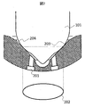
- FIG. 2 is an enlarged cross-sectional view of the vicinity of the contact point between the valve body surface of the valve body 101 provided at the tip of the valve body and the valve seat surface of the seat member 102.
- valve body surface 202 of the valve body 101 is formed into a spherical surface, and the contact between the valve seat surface 203 having a conical surface and the spherical valve body surface 204 forms a seal seat 202, and the seal seat 202 is It is almost in line contact.
- the seal seat 202 formed between the valve body surface 204 and the valve seat surface 203 needs to be formed without interruption in an annular shape.
- the supplied fuel pressure is in the range of about 2 MPa to 30 MPa.
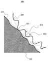
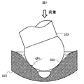
- FIG. 3 is a microscopic illustration of the contact state between the valve body surface 204 and the valve seat surface 203 of a fuel injection valve not using the present invention. From FIG. 3, due to the non-circularity of the valve body surface 204 and the valve seat surface 203, the contact point between the valve body surface 204 and the valve seat surface 203 is not intended to deviate from the designed seat width 302 to be seated. It shows that the contact position 301 is in a wide contact state.
- the design seat width 302 means that the valve body surface 204 which is an ideal true sphere and the valve seat surface 203 which is an ideal cone centering on the position 303 where the seat should be designed are centered.
- Within the range of the load acting on the valve body surface 204 and the valve seat surface 203 is a width in the slant direction of contact produced as a result of deformation due to Hertz stress, and this width is usually within about 50 ⁇ m.
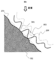
- FIG. 4 is a schematic diagram microscopically illustrating a contact state when the valve seat surface 204 and the valve body surface 203 are deformed by a pressing force such as a biasing spring 110 or a force due to fuel pressure.
- a pressing force such as a biasing spring 110 or a force due to fuel pressure.
- the convex portion at an unintended location 301 is made to have a seat width at a designed seat position by a pressing force such as an urging spring or fuel pressure.
- the seal seat 202 needs to be formed without interruption in an annular shape by being deformed until contact is made over 302.
- the contact rigidity is improved by the amount of the convex portion 302 caused by the non-circularity, the design seat portion 301 comes into contact over the entire circumference, and the load necessary for forming the seal seat 202 in an annular shape is large. Become. At this time, if the load for forming the seal seat 202 in an annular shape is insufficient, a gap remains between the valve body surface 203 and the valve seat surface 204, and fuel leakage occurs.
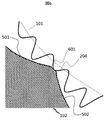
- an upstream concave portion 501 having a curvature radius larger than the spherical diameter SR 3 of the valve body is provided on the upstream valve seat surface 204 of the seat position (the position of the seal seat 202). the downstream side of the seat position and structure in which the downstream side of the recess 502 the radius of curvature is smaller than the spherical diameter SR 3 of the valve body.
- the valve body surface 204 and the flat surface portion 601 come into contact with each other.
- An increase in contact force with the valve seat surface 203 can be suppressed.
- the width of the spherical surface portion 601 is preferably larger than the width of the line contact when the valve body surface 204 that does not have non-roundness and the valve seat surface 203 that does not have non-roundness contact.
- a spherical tool having the same spherical diameters SR 1 and SR 2 as the upstream concave portion 501 and the downstream concave portion 502 as shown in FIG. 701 is used.
- the spherical tool 701 having the spherical diameters SR 1 and SR 2 the desired upstream recess 501 and downstream recess 502 can be obtained.
- the contact position between the spherical tool 701 and the valve seat surface 203 is a line contact due to the geometric relationship between the sphere and the tapered conical surface, and the contact position is uniquely determined, so that a concave portion can be formed with high accuracy. is there.
- the order of forming the spherical tool 701 having the spherical diameter SR 1 and the spherical tool 701 having the spherical diameter SR 2 and the obtained effect are irrelevant, and whichever of the upstream concave portion 501 and the downstream concave portion 502 is selected first. You may form in.
- the spherical diameter SR 1 used for forming the upstream concave portion 501 to be used is a large spherical diameter of about 10 to 25% of the spherical diameter SR 3 of the valve body, and the downstream concave portion 502 is formed.
- the spherical diameter SR 2 used for cutting is 10 to 25% smaller than the spherical diameter SR 3 of the valve body, the desired effect can be obtained while suppressing the grinding amount for forming the recess. it can. Further, by using a spherical tool 701 having the same spherical diameter SR 3 as that of the valve body as a finish after grinding and polishing the valve seat surface 203 and the spherical tool 701, the sealing performance can be further improved. .
- the above-described forming method has mainly described the method of forming the upstream recessed portion 501 and the downstream recessed portion 502 by grinding, it is not always necessary to use grinding to form the upstream recessed portion 501 and the downstream recessed portion 502.
- processing by polishing is mentioned.
- the desired effect can also be obtained by smoothing the convex portion of the portion where the wide contact can occur on the upstream side or the downstream side of the sheet position by the grinding process using the spherical tool 701. This grinding can be processed with extremely high precision because the grinding amount is very small and a desired effect can be obtained when forming the upstream recess 501 and the downstream recess 502.
- the spherical diameter SR 1 used for forming the upstream concave portion 501 to be used is a large spherical diameter of about 1 to 10% of the spherical diameter SR 3 of the valve body, and the downstream concave portion 502 is formed.
- a sphere diameter SR 2 used for forming a sphere diameter as small as about 1 to 10% is used, a region having a width of about 100 ⁇ m where a wide contact may occur can be finished to a smooth surface.
- the sealing performance can be further improved by polishing the valve seat surface and the spherical tool by using the spherical tool 701 having the same spherical diameter SR 3 as the valve body as a finish.
- the smooth portion 601 can reduce the distance to the valve body surface 201 from the upstream concave portion 501 and the downstream concave portion 502, the effect of suppressing wide contact can be further increased.
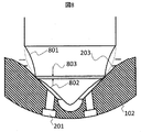
- FIG. 8 is an enlarged sectional view of the vicinity of the valve body 801 showing a second embodiment according to the present invention.
- annular recesses 801, 802 or slopes are provided on the upstream side and the downstream side of the seat position of the valve body 801.
- the method of avoiding wide contact by providing a relief on the valve body side is particularly effective for the case of manufacturing by transferring the shape of the valve body.
- the clearance between the valve body and the seat conical surface is enlarged on the upstream side and the downstream side from the seat position by processing the valve body without processing the valve seat side.
- the distance 803 between the upstream concave portion 801 and the downstream concave portion 802 is set to the width of the line contact when the valve body surface 204 that does not have non-circularity and the valve seat surface 203 that does not have non-circularity contact.
- FIG. 9 is an enlarged view microscopically showing seat portions of the valve body 901 and the valve seat portion 102.
- Upstream concave portion, 502 ... Downstream concave portion, 601 ... Flat portion, 701 ... Spherical tool, 801 ... Upstream side Recessed portion, 802... Downstream recessed portion, 803... Spherical surface portion, 901... Valve body surface having non-roundness.
Landscapes
- Engineering & Computer Science (AREA)
- Chemical & Material Sciences (AREA)
- Combustion & Propulsion (AREA)
- Mechanical Engineering (AREA)
- General Engineering & Computer Science (AREA)
- Manufacturing & Machinery (AREA)
- Physics & Mathematics (AREA)
- Electromagnetism (AREA)
- Fuel-Injection Apparatus (AREA)
Abstract
Description
Claims (7)
- 弁座面を有するシート部材と、前記弁座面と当接する弁体面を有する弁部材と、前記弁部材を往復動作させる弁駆動手段とを備え、前記弁駆動手段により弁部材を往復動作させることにより前記弁体面を前記弁座面に接触させることにより弁を閉じ、前記弁体面を前記弁座面から離間させることにより弁を開く燃料噴射弁において、
前記弁座面または前記弁体面の少なくともどちらか一方の、前記弁体面と前記弁座面とが接触するシール座に対して上流側部分および下流側部分に凹部を設けたことを特徴とする燃料噴射弁。 - 請求項1に記載の燃料噴射弁において、
前記凹部は予め形成された前記弁座面に加工された形状部分であることを特徴とする燃料噴射弁。 - 請求項2に記載の燃料噴射弁において、
前記上流側の凹部と前記下流側の凹部とが球面の一部として形成され、前記上流側の凹部の球面の曲率半径は前記下流側の凹部の曲率半径よりも大きいことを特徴とする燃料噴射弁。 - 請求項3に記載の燃料噴射弁において、
前記上流側の凹部と前記下流側の凹部との間に平坦部を有することを特徴とする燃料噴射弁。 - 請求項4に記載の燃料噴射弁において、
前記上流側の凹部と前記下流側の凹部とは、径の異なる球面状のツールを使用して形成されたことを特徴とする燃料噴射弁。 - 請求項5に記載の燃料噴射弁において、
前記上流側の凹部と前記下流側の凹部との間に球面部を形成したことを特徴とする燃料噴射弁。 - 請求項1に記載の燃料噴射弁において、
前記凹部は前記弁体面に設けられ、前記弁体の曲率線より凹んだ形状に形成されていることを特徴とする燃料噴射弁。
Priority Applications (3)
| Application Number | Priority Date | Filing Date | Title |
|---|---|---|---|
| US14/421,563 US20150233334A1 (en) | 2012-08-27 | 2013-07-22 | Fuel Injection Valve |
| DE112013004206.1T DE112013004206T5 (de) | 2012-08-27 | 2013-07-22 | Kraftstoffeinspritzventil |
| CN201380041263.0A CN104520576B (zh) | 2012-08-27 | 2013-07-22 | 燃料喷射阀 |
Applications Claiming Priority (2)
| Application Number | Priority Date | Filing Date | Title |
|---|---|---|---|
| JP2012186051A JP6059915B2 (ja) | 2012-08-27 | 2012-08-27 | 燃料噴射弁 |
| JP2012-186051 | 2012-08-27 |
Publications (1)
| Publication Number | Publication Date |
|---|---|
| WO2014034322A1 true WO2014034322A1 (ja) | 2014-03-06 |
Family
ID=50183142
Family Applications (1)
| Application Number | Title | Priority Date | Filing Date |
|---|---|---|---|
| PCT/JP2013/069725 Ceased WO2014034322A1 (ja) | 2012-08-27 | 2013-07-22 | 燃料噴射弁 |
Country Status (5)
| Country | Link |
|---|---|
| US (1) | US20150233334A1 (ja) |
| JP (1) | JP6059915B2 (ja) |
| CN (1) | CN104520576B (ja) |
| DE (1) | DE112013004206T5 (ja) |
| WO (1) | WO2014034322A1 (ja) |
Cited By (2)
| Publication number | Priority date | Publication date | Assignee | Title |
|---|---|---|---|---|
| CN106795848A (zh) * | 2014-10-23 | 2017-05-31 | 株式会社电装 | 燃料喷射阀 |
| JP2019112984A (ja) * | 2017-12-22 | 2019-07-11 | 日立オートモティブシステムズ株式会社 | 燃料噴射弁 |
Families Citing this family (4)
| Publication number | Priority date | Publication date | Assignee | Title |
|---|---|---|---|---|
| EP3156641A1 (en) * | 2015-10-14 | 2017-04-19 | Continental Automotive GmbH | Injector for injecting fluid |
| DE102015226769A1 (de) * | 2015-12-29 | 2017-06-29 | Robert Bosch Gmbh | Brennstoffeinspritzventil |
| JP6776685B2 (ja) | 2016-07-21 | 2020-10-28 | セイコーエプソン株式会社 | 流体吐出装置 |
| JP7124351B2 (ja) * | 2018-03-08 | 2022-08-24 | 株式会社デンソー | 燃料噴射弁および燃料噴射システム |
Citations (7)
| Publication number | Priority date | Publication date | Assignee | Title |
|---|---|---|---|---|
| FR981999A (fr) * | 1943-05-28 | 1951-06-01 | Citroen Sa Andre | Dispositifs obturateurs et leur procédé de fabrication |
| JP2004197627A (ja) * | 2002-12-18 | 2004-07-15 | Bosch Automotive Systems Corp | 燃料噴射ノズル |
| JP2005337192A (ja) * | 2004-05-31 | 2005-12-08 | Mitsubishi Electric Corp | 燃料噴射弁、及び最小隙間決定方法 |
| JP2007056876A (ja) * | 2005-08-24 | 2007-03-08 | Delphi Technologies Inc | 内燃エンジン用インジェクションノズル |
| JP2007507638A (ja) * | 2003-09-29 | 2007-03-29 | シーメンス ヴィディーオー オートモティヴ コーポレイション | 圧印シールバンドを有する噴射器シール |
| JP2007231771A (ja) * | 2006-02-28 | 2007-09-13 | Toyota Motor Corp | 燃料噴射弁 |
| JP2011506849A (ja) * | 2007-12-21 | 2011-03-03 | ローベルト ボツシユ ゲゼルシヤフト ミツト ベシユレンクテル ハフツング | 燃料噴射弁 |
Family Cites Families (23)
| Publication number | Priority date | Publication date | Assignee | Title |
|---|---|---|---|---|
| US1952816A (en) * | 1931-04-04 | 1934-03-27 | Bendix Res Corp | Fuel injector |
| US3191277A (en) * | 1961-05-17 | 1965-06-29 | Clarence O Glasgow | Valve seat |
| US4417694A (en) * | 1980-10-22 | 1983-11-29 | The Bendix Corporation | Injector valve with contoured valve seat and needle valve interface |
| DE3312067A1 (de) * | 1983-04-02 | 1984-10-04 | Robert Bosch Gmbh, 7000 Stuttgart | Elektromagnetisch betaetigbares ventil |
| DE3714693A1 (de) * | 1987-05-02 | 1988-11-10 | Bosch Gmbh Robert | Elektromagnetisch betaetigbares ventil |
| JP2819702B2 (ja) * | 1989-12-12 | 1998-11-05 | 株式会社デンソー | 燃料噴射弁 |
| DE4037952A1 (de) * | 1990-11-29 | 1992-06-04 | Bosch Gmbh Robert | Verfahren zur montage eines filters an einem ventil und ventil |
| DE4137994C2 (de) * | 1991-11-19 | 1999-06-02 | Bosch Gmbh Robert | Elektromagnetisch betätigbares Einspritzventil mit einem Düsenträger und Verfahren zur Herstellung eines Düsenträgers eines Einspritzventils |
| DE19527049A1 (de) * | 1995-07-25 | 1997-01-30 | Bosch Gmbh Robert | Brennstoffeinspritzventil |
| DE19653832A1 (de) * | 1996-12-21 | 1998-06-25 | Bosch Gmbh Robert | Ventil mit kombiniertem Ventilsitzkörper und Spritzlochscheibe |
| DE19726991A1 (de) * | 1997-06-25 | 1999-01-07 | Bosch Gmbh Robert | Ventil und Verfahren zur Herstellung eines Ventilsitzes für ein Ventil |
| DE19757117A1 (de) * | 1997-12-20 | 1999-06-24 | Bosch Gmbh Robert | Verfahren zur Herstellung eines Ventilsitzkörpers für ein Brennstoffeinspritzventil und Brennstoffeinspritzventil |
| US6098958A (en) * | 1998-05-06 | 2000-08-08 | Ernst Thielenhaus Kg | Valve assembly, especially for a fuel-injection valve and method of making same |
| DE19820513A1 (de) * | 1998-05-08 | 1999-11-11 | Mtu Friedrichshafen Gmbh | Kraftstoffeinspritzdüse für eine Brennkraftmaschine |
| DE19856920A1 (de) * | 1998-12-10 | 2000-06-15 | Bosch Gmbh Robert | Brennstoffeinspritzventil |
| DE19931891A1 (de) * | 1999-07-08 | 2001-01-18 | Siemens Ag | Kraftstoffeinspritzventil für eine Brennkraftmaschine |
| JP3837282B2 (ja) * | 2000-10-24 | 2006-10-25 | 株式会社ケーヒン | 燃料噴射弁 |
| DE10054183A1 (de) * | 2000-11-02 | 2002-05-29 | Siemens Ag | Einspritznadel mit elastischer Nadelspitze |
| DE10247958A1 (de) * | 2002-10-15 | 2004-04-29 | Robert Bosch Gmbh | Kraftstoff-Einspritzvorrichtung für eine Brennkraftmaschine |
| US7334746B2 (en) * | 2004-03-08 | 2008-02-26 | Continental Automotive Systems Us, Inc. | Seat-lower guide combination |
| KR101019324B1 (ko) * | 2007-01-29 | 2011-03-07 | 미쓰비시덴키 가부시키가이샤 | 연료 분사 밸브 |
| JP6138502B2 (ja) * | 2013-02-04 | 2017-05-31 | 日立オートモティブシステムズ株式会社 | 燃料噴射弁 |
| JP6264221B2 (ja) * | 2014-07-24 | 2018-01-24 | 株式会社デンソー | 燃料噴射ノズル |
-
2012
- 2012-08-27 JP JP2012186051A patent/JP6059915B2/ja not_active Expired - Fee Related
-
2013
- 2013-07-22 US US14/421,563 patent/US20150233334A1/en not_active Abandoned
- 2013-07-22 WO PCT/JP2013/069725 patent/WO2014034322A1/ja not_active Ceased
- 2013-07-22 DE DE112013004206.1T patent/DE112013004206T5/de not_active Withdrawn
- 2013-07-22 CN CN201380041263.0A patent/CN104520576B/zh not_active Expired - Fee Related
Patent Citations (7)
| Publication number | Priority date | Publication date | Assignee | Title |
|---|---|---|---|---|
| FR981999A (fr) * | 1943-05-28 | 1951-06-01 | Citroen Sa Andre | Dispositifs obturateurs et leur procédé de fabrication |
| JP2004197627A (ja) * | 2002-12-18 | 2004-07-15 | Bosch Automotive Systems Corp | 燃料噴射ノズル |
| JP2007507638A (ja) * | 2003-09-29 | 2007-03-29 | シーメンス ヴィディーオー オートモティヴ コーポレイション | 圧印シールバンドを有する噴射器シール |
| JP2005337192A (ja) * | 2004-05-31 | 2005-12-08 | Mitsubishi Electric Corp | 燃料噴射弁、及び最小隙間決定方法 |
| JP2007056876A (ja) * | 2005-08-24 | 2007-03-08 | Delphi Technologies Inc | 内燃エンジン用インジェクションノズル |
| JP2007231771A (ja) * | 2006-02-28 | 2007-09-13 | Toyota Motor Corp | 燃料噴射弁 |
| JP2011506849A (ja) * | 2007-12-21 | 2011-03-03 | ローベルト ボツシユ ゲゼルシヤフト ミツト ベシユレンクテル ハフツング | 燃料噴射弁 |
Cited By (3)
| Publication number | Priority date | Publication date | Assignee | Title |
|---|---|---|---|---|
| CN106795848A (zh) * | 2014-10-23 | 2017-05-31 | 株式会社电装 | 燃料喷射阀 |
| CN106795848B (zh) * | 2014-10-23 | 2019-11-29 | 株式会社电装 | 燃料喷射阀 |
| JP2019112984A (ja) * | 2017-12-22 | 2019-07-11 | 日立オートモティブシステムズ株式会社 | 燃料噴射弁 |
Also Published As
| Publication number | Publication date |
|---|---|
| CN104520576A (zh) | 2015-04-15 |
| DE112013004206T5 (de) | 2015-06-25 |
| CN104520576B (zh) | 2017-12-22 |
| JP6059915B2 (ja) | 2017-01-11 |
| JP2014043799A (ja) | 2014-03-13 |
| US20150233334A1 (en) | 2015-08-20 |
Similar Documents
| Publication | Publication Date | Title |
|---|---|---|
| JP6059915B2 (ja) | 燃料噴射弁 | |
| US20090217523A1 (en) | Remanufactured machine component and valve body remanufacturing process | |
| CN1084857C (zh) | 燃料喷射器阀座内的槽装置 | |
| US11242831B2 (en) | Fuel injection valve | |
| JP4594338B2 (ja) | 噴射弁、噴射弁のオリフィスプレートおよびその製造方法 | |
| JP6039492B2 (ja) | 燃料噴射弁及びその製造方法 | |
| US9079281B2 (en) | Common rail valve seat refurbishing | |
| US11421636B2 (en) | Fuel injection valve | |
| WO2015136974A1 (ja) | 電磁式弁 | |
| US8474140B2 (en) | High precision grinding and remanufacturing of machine components | |
| JP3431378B2 (ja) | 弁のシール面の仕上加工方法および弁のシール面の仕上加工装置および弁装置 | |
| WO2019065406A1 (ja) | 燃料噴射弁および燃料噴射弁の製造方法 | |
| US20210332780A1 (en) | Fuel injection valve | |
| JP4039370B2 (ja) | オリフィスの加工方法 | |
| US6976381B2 (en) | Fuel injector, nozzle body, and manufacturing method of cylindrical part equipped with fluid passage | |
| JP2012200823A (ja) | メタルシール部の加工方法および加工装置 | |
| US20200224619A1 (en) | Fuel injection valve | |
| JP6724959B2 (ja) | 燃料噴射弁 | |
| US8046917B2 (en) | Method of refurbishing a diesel injector valve seat | |
| CN103600146B (zh) | 高压共轨柴油发动机喷油器微小球座面精密电磨削工艺 | |
| JP3954046B2 (ja) | 燃料噴射弁、弁座体、及び弁座体の工作方法 | |
| CN113250872A (zh) | 一种自动对中的柱塞结构 | |
| US11542901B2 (en) | Fuel injection valve | |
| JP4123053B2 (ja) | 燃料噴射弁 | |
| JPS5843582B2 (ja) | ナイネンキカンヨウネンリヨウフンシヤキ |
Legal Events
| Date | Code | Title | Description |
|---|---|---|---|
| 121 | Ep: the epo has been informed by wipo that ep was designated in this application |
Ref document number: 13832923 Country of ref document: EP Kind code of ref document: A1 |
|
| WWE | Wipo information: entry into national phase |
Ref document number: 14421563 Country of ref document: US |
|
| WWE | Wipo information: entry into national phase |
Ref document number: 112013004206 Country of ref document: DE Ref document number: 1120130042061 Country of ref document: DE |
|
| 122 | Ep: pct application non-entry in european phase |
Ref document number: 13832923 Country of ref document: EP Kind code of ref document: A1 |