WO2014034113A1 - Electricity storage device and method for producing same - Google Patents
Electricity storage device and method for producing same Download PDFInfo
- Publication number
- WO2014034113A1 WO2014034113A1 PCT/JP2013/005096 JP2013005096W WO2014034113A1 WO 2014034113 A1 WO2014034113 A1 WO 2014034113A1 JP 2013005096 W JP2013005096 W JP 2013005096W WO 2014034113 A1 WO2014034113 A1 WO 2014034113A1
- Authority
- WO
- WIPO (PCT)
- Prior art keywords
- undercoat layer
- storage device
- electricity storage
- active material
- tab lead
- Prior art date
Links
Images


Classifications
-
- H—ELECTRICITY
- H01—ELECTRIC ELEMENTS
- H01G—CAPACITORS; CAPACITORS, RECTIFIERS, DETECTORS, SWITCHING DEVICES OR LIGHT-SENSITIVE DEVICES, OF THE ELECTROLYTIC TYPE
- H01G11/00—Hybrid capacitors, i.e. capacitors having different positive and negative electrodes; Electric double-layer [EDL] capacitors; Processes for the manufacture thereof or of parts thereof
- H01G11/22—Electrodes
- H01G11/30—Electrodes characterised by their material
- H01G11/32—Carbon-based
- H01G11/36—Nanostructures, e.g. nanofibres, nanotubes or fullerenes
-
- H—ELECTRICITY
- H01—ELECTRIC ELEMENTS
- H01G—CAPACITORS; CAPACITORS, RECTIFIERS, DETECTORS, SWITCHING DEVICES OR LIGHT-SENSITIVE DEVICES, OF THE ELECTROLYTIC TYPE
- H01G11/00—Hybrid capacitors, i.e. capacitors having different positive and negative electrodes; Electric double-layer [EDL] capacitors; Processes for the manufacture thereof or of parts thereof
- H01G11/22—Electrodes
- H01G11/26—Electrodes characterised by their structure, e.g. multi-layered, porosity or surface features
- H01G11/28—Electrodes characterised by their structure, e.g. multi-layered, porosity or surface features arranged or disposed on a current collector; Layers or phases between electrodes and current collectors, e.g. adhesives
-
- H—ELECTRICITY
- H01—ELECTRIC ELEMENTS
- H01G—CAPACITORS; CAPACITORS, RECTIFIERS, DETECTORS, SWITCHING DEVICES OR LIGHT-SENSITIVE DEVICES, OF THE ELECTROLYTIC TYPE
- H01G11/00—Hybrid capacitors, i.e. capacitors having different positive and negative electrodes; Electric double-layer [EDL] capacitors; Processes for the manufacture thereof or of parts thereof
- H01G11/22—Electrodes
- H01G11/30—Electrodes characterised by their material
- H01G11/32—Carbon-based
- H01G11/38—Carbon pastes or blends; Binders or additives therein
-
- H—ELECTRICITY
- H01—ELECTRIC ELEMENTS
- H01G—CAPACITORS; CAPACITORS, RECTIFIERS, DETECTORS, SWITCHING DEVICES OR LIGHT-SENSITIVE DEVICES, OF THE ELECTROLYTIC TYPE
- H01G11/00—Hybrid capacitors, i.e. capacitors having different positive and negative electrodes; Electric double-layer [EDL] capacitors; Processes for the manufacture thereof or of parts thereof
- H01G11/66—Current collectors
- H01G11/72—Current collectors specially adapted for integration in multiple or stacked hybrid or EDL capacitors
-
- H—ELECTRICITY
- H01—ELECTRIC ELEMENTS
- H01G—CAPACITORS; CAPACITORS, RECTIFIERS, DETECTORS, SWITCHING DEVICES OR LIGHT-SENSITIVE DEVICES, OF THE ELECTROLYTIC TYPE
- H01G11/00—Hybrid capacitors, i.e. capacitors having different positive and negative electrodes; Electric double-layer [EDL] capacitors; Processes for the manufacture thereof or of parts thereof
- H01G11/84—Processes for the manufacture of hybrid or EDL capacitors, or components thereof
- H01G11/86—Processes for the manufacture of hybrid or EDL capacitors, or components thereof specially adapted for electrodes
-
- H—ELECTRICITY
- H01—ELECTRIC ELEMENTS
- H01M—PROCESSES OR MEANS, e.g. BATTERIES, FOR THE DIRECT CONVERSION OF CHEMICAL ENERGY INTO ELECTRICAL ENERGY
- H01M10/00—Secondary cells; Manufacture thereof
- H01M10/05—Accumulators with non-aqueous electrolyte
- H01M10/052—Li-accumulators
-
- H—ELECTRICITY
- H01—ELECTRIC ELEMENTS
- H01M—PROCESSES OR MEANS, e.g. BATTERIES, FOR THE DIRECT CONVERSION OF CHEMICAL ENERGY INTO ELECTRICAL ENERGY
- H01M10/00—Secondary cells; Manufacture thereof
- H01M10/05—Accumulators with non-aqueous electrolyte
- H01M10/052—Li-accumulators
- H01M10/0525—Rocking-chair batteries, i.e. batteries with lithium insertion or intercalation in both electrodes; Lithium-ion batteries
-
- H—ELECTRICITY
- H01—ELECTRIC ELEMENTS
- H01M—PROCESSES OR MEANS, e.g. BATTERIES, FOR THE DIRECT CONVERSION OF CHEMICAL ENERGY INTO ELECTRICAL ENERGY
- H01M4/00—Electrodes
- H01M4/02—Electrodes composed of, or comprising, active material
- H01M4/13—Electrodes for accumulators with non-aqueous electrolyte, e.g. for lithium-accumulators; Processes of manufacture thereof
- H01M4/133—Electrodes based on carbonaceous material, e.g. graphite-intercalation compounds or CFx
-
- H—ELECTRICITY
- H01—ELECTRIC ELEMENTS
- H01M—PROCESSES OR MEANS, e.g. BATTERIES, FOR THE DIRECT CONVERSION OF CHEMICAL ENERGY INTO ELECTRICAL ENERGY
- H01M4/00—Electrodes
- H01M4/02—Electrodes composed of, or comprising, active material
- H01M4/36—Selection of substances as active materials, active masses, active liquids
- H01M4/362—Composites
- H01M4/366—Composites as layered products
-
- H—ELECTRICITY
- H01—ELECTRIC ELEMENTS
- H01M—PROCESSES OR MEANS, e.g. BATTERIES, FOR THE DIRECT CONVERSION OF CHEMICAL ENERGY INTO ELECTRICAL ENERGY
- H01M4/00—Electrodes
- H01M4/02—Electrodes composed of, or comprising, active material
- H01M4/36—Selection of substances as active materials, active masses, active liquids
- H01M4/58—Selection of substances as active materials, active masses, active liquids of inorganic compounds other than oxides or hydroxides, e.g. sulfides, selenides, tellurides, halogenides or LiCoFy; of polyanionic structures, e.g. phosphates, silicates or borates
- H01M4/583—Carbonaceous material, e.g. graphite-intercalation compounds or CFx
- H01M4/587—Carbonaceous material, e.g. graphite-intercalation compounds or CFx for inserting or intercalating light metals
-
- H—ELECTRICITY
- H01—ELECTRIC ELEMENTS
- H01M—PROCESSES OR MEANS, e.g. BATTERIES, FOR THE DIRECT CONVERSION OF CHEMICAL ENERGY INTO ELECTRICAL ENERGY
- H01M4/00—Electrodes
- H01M4/02—Electrodes composed of, or comprising, active material
- H01M4/64—Carriers or collectors
- H01M4/66—Selection of materials
- H01M4/661—Metal or alloys, e.g. alloy coatings
-
- H—ELECTRICITY
- H01—ELECTRIC ELEMENTS
- H01M—PROCESSES OR MEANS, e.g. BATTERIES, FOR THE DIRECT CONVERSION OF CHEMICAL ENERGY INTO ELECTRICAL ENERGY
- H01M4/00—Electrodes
- H01M4/02—Electrodes composed of, or comprising, active material
- H01M4/64—Carriers or collectors
- H01M4/66—Selection of materials
- H01M4/663—Selection of materials containing carbon or carbonaceous materials as conductive part, e.g. graphite, carbon fibres
-
- H—ELECTRICITY
- H01—ELECTRIC ELEMENTS
- H01M—PROCESSES OR MEANS, e.g. BATTERIES, FOR THE DIRECT CONVERSION OF CHEMICAL ENERGY INTO ELECTRICAL ENERGY
- H01M4/00—Electrodes
- H01M4/02—Electrodes composed of, or comprising, active material
- H01M4/64—Carriers or collectors
- H01M4/66—Selection of materials
- H01M4/665—Composites
- H01M4/667—Composites in the form of layers, e.g. coatings
-
- H—ELECTRICITY
- H01—ELECTRIC ELEMENTS
- H01G—CAPACITORS; CAPACITORS, RECTIFIERS, DETECTORS, SWITCHING DEVICES OR LIGHT-SENSITIVE DEVICES, OF THE ELECTROLYTIC TYPE
- H01G11/00—Hybrid capacitors, i.e. capacitors having different positive and negative electrodes; Electric double-layer [EDL] capacitors; Processes for the manufacture thereof or of parts thereof
- H01G11/04—Hybrid capacitors
-
- H—ELECTRICITY
- H01—ELECTRIC ELEMENTS
- H01G—CAPACITORS; CAPACITORS, RECTIFIERS, DETECTORS, SWITCHING DEVICES OR LIGHT-SENSITIVE DEVICES, OF THE ELECTROLYTIC TYPE
- H01G11/00—Hybrid capacitors, i.e. capacitors having different positive and negative electrodes; Electric double-layer [EDL] capacitors; Processes for the manufacture thereof or of parts thereof
- H01G11/74—Terminals, e.g. extensions of current collectors
- H01G11/76—Terminals, e.g. extensions of current collectors specially adapted for integration in multiple or stacked hybrid or EDL capacitors
-
- H—ELECTRICITY
- H01—ELECTRIC ELEMENTS
- H01M—PROCESSES OR MEANS, e.g. BATTERIES, FOR THE DIRECT CONVERSION OF CHEMICAL ENERGY INTO ELECTRICAL ENERGY
- H01M10/00—Secondary cells; Manufacture thereof
- H01M10/05—Accumulators with non-aqueous electrolyte
- H01M10/058—Construction or manufacture
-
- H—ELECTRICITY
- H01—ELECTRIC ELEMENTS
- H01M—PROCESSES OR MEANS, e.g. BATTERIES, FOR THE DIRECT CONVERSION OF CHEMICAL ENERGY INTO ELECTRICAL ENERGY
- H01M50/00—Constructional details or processes of manufacture of the non-active parts of electrochemical cells other than fuel cells, e.g. hybrid cells
- H01M50/50—Current conducting connections for cells or batteries
- H01M50/531—Electrode connections inside a battery casing
- H01M50/534—Electrode connections inside a battery casing characterised by the material of the leads or tabs
-
- H—ELECTRICITY
- H01—ELECTRIC ELEMENTS
- H01M—PROCESSES OR MEANS, e.g. BATTERIES, FOR THE DIRECT CONVERSION OF CHEMICAL ENERGY INTO ELECTRICAL ENERGY
- H01M50/00—Constructional details or processes of manufacture of the non-active parts of electrochemical cells other than fuel cells, e.g. hybrid cells
- H01M50/50—Current conducting connections for cells or batteries
- H01M50/531—Electrode connections inside a battery casing
- H01M50/536—Electrode connections inside a battery casing characterised by the method of fixing the leads to the electrodes, e.g. by welding
-
- H—ELECTRICITY
- H01—ELECTRIC ELEMENTS
- H01M—PROCESSES OR MEANS, e.g. BATTERIES, FOR THE DIRECT CONVERSION OF CHEMICAL ENERGY INTO ELECTRICAL ENERGY
- H01M50/00—Constructional details or processes of manufacture of the non-active parts of electrochemical cells other than fuel cells, e.g. hybrid cells
- H01M50/50—Current conducting connections for cells or batteries
- H01M50/531—Electrode connections inside a battery casing
- H01M50/54—Connection of several leads or tabs of plate-like electrode stacks, e.g. electrode pole straps or bridges
-
- Y—GENERAL TAGGING OF NEW TECHNOLOGICAL DEVELOPMENTS; GENERAL TAGGING OF CROSS-SECTIONAL TECHNOLOGIES SPANNING OVER SEVERAL SECTIONS OF THE IPC; TECHNICAL SUBJECTS COVERED BY FORMER USPC CROSS-REFERENCE ART COLLECTIONS [XRACs] AND DIGESTS
- Y02—TECHNOLOGIES OR APPLICATIONS FOR MITIGATION OR ADAPTATION AGAINST CLIMATE CHANGE
- Y02E—REDUCTION OF GREENHOUSE GAS [GHG] EMISSIONS, RELATED TO ENERGY GENERATION, TRANSMISSION OR DISTRIBUTION
- Y02E60/00—Enabling technologies; Technologies with a potential or indirect contribution to GHG emissions mitigation
- Y02E60/10—Energy storage using batteries
-
- Y—GENERAL TAGGING OF NEW TECHNOLOGICAL DEVELOPMENTS; GENERAL TAGGING OF CROSS-SECTIONAL TECHNOLOGIES SPANNING OVER SEVERAL SECTIONS OF THE IPC; TECHNICAL SUBJECTS COVERED BY FORMER USPC CROSS-REFERENCE ART COLLECTIONS [XRACs] AND DIGESTS
- Y02—TECHNOLOGIES OR APPLICATIONS FOR MITIGATION OR ADAPTATION AGAINST CLIMATE CHANGE
- Y02E—REDUCTION OF GREENHOUSE GAS [GHG] EMISSIONS, RELATED TO ENERGY GENERATION, TRANSMISSION OR DISTRIBUTION
- Y02E60/00—Enabling technologies; Technologies with a potential or indirect contribution to GHG emissions mitigation
- Y02E60/13—Energy storage using capacitors
-
- Y—GENERAL TAGGING OF NEW TECHNOLOGICAL DEVELOPMENTS; GENERAL TAGGING OF CROSS-SECTIONAL TECHNOLOGIES SPANNING OVER SEVERAL SECTIONS OF THE IPC; TECHNICAL SUBJECTS COVERED BY FORMER USPC CROSS-REFERENCE ART COLLECTIONS [XRACs] AND DIGESTS
- Y02—TECHNOLOGIES OR APPLICATIONS FOR MITIGATION OR ADAPTATION AGAINST CLIMATE CHANGE
- Y02P—CLIMATE CHANGE MITIGATION TECHNOLOGIES IN THE PRODUCTION OR PROCESSING OF GOODS
- Y02P70/00—Climate change mitigation technologies in the production process for final industrial or consumer products
- Y02P70/50—Manufacturing or production processes characterised by the final manufactured product
-
- Y—GENERAL TAGGING OF NEW TECHNOLOGICAL DEVELOPMENTS; GENERAL TAGGING OF CROSS-SECTIONAL TECHNOLOGIES SPANNING OVER SEVERAL SECTIONS OF THE IPC; TECHNICAL SUBJECTS COVERED BY FORMER USPC CROSS-REFERENCE ART COLLECTIONS [XRACs] AND DIGESTS
- Y02—TECHNOLOGIES OR APPLICATIONS FOR MITIGATION OR ADAPTATION AGAINST CLIMATE CHANGE
- Y02T—CLIMATE CHANGE MITIGATION TECHNOLOGIES RELATED TO TRANSPORTATION
- Y02T10/00—Road transport of goods or passengers
- Y02T10/60—Other road transportation technologies with climate change mitigation effect
- Y02T10/70—Energy storage systems for electromobility, e.g. batteries
-
- Y—GENERAL TAGGING OF NEW TECHNOLOGICAL DEVELOPMENTS; GENERAL TAGGING OF CROSS-SECTIONAL TECHNOLOGIES SPANNING OVER SEVERAL SECTIONS OF THE IPC; TECHNICAL SUBJECTS COVERED BY FORMER USPC CROSS-REFERENCE ART COLLECTIONS [XRACs] AND DIGESTS
- Y10—TECHNICAL SUBJECTS COVERED BY FORMER USPC
- Y10T—TECHNICAL SUBJECTS COVERED BY FORMER US CLASSIFICATION
- Y10T29/00—Metal working
- Y10T29/49—Method of mechanical manufacture
- Y10T29/49002—Electrical device making
- Y10T29/49108—Electric battery cell making
Definitions
- the present invention relates to a power storage device and a manufacturing method thereof. More specifically, the present invention relates to an electricity storage device including an electrode formed by welding a single metal tab lead and a plurality of electrode plates, and a method for manufacturing the same.
- a secondary battery such as a nickel metal hydride battery, a nickel cadmium battery, a lead storage battery, or a lithium ion secondary battery, or a capacitor such as an electric double layer capacitor or a lithium ion capacitor is known.
- lithium ion secondary batteries are used in electric vehicles and hybrid vehicles.
- the electric double layer capacitor is used as a backup power source in the event of an instantaneous power failure.
- the lithium ion secondary battery has at least a positive electrode plate and a negative electrode plate.
- the positive electrode plate is formed by forming a positive electrode active material layer on a current collector such as an aluminum foil.
- a current collector such as an aluminum foil.
- an oxide of a transition metal containing lithium or the like is used as the positive electrode active material.
- the negative electrode plate is formed by forming a negative electrode active material layer on a negative electrode current collector such as a copper foil.
- a carbon material such as graphite is used as the negative electrode active material.
- Metal tab leads are welded to the positive electrode plate and the negative electrode plate, respectively, as terminals for extracting current from the positive electrode plate and the negative electrode plate. The metal tab lead is welded in the portion where the current collector is exposed.
- the electric double layer capacitor has at least a pair of electrode plates.
- the electrode plate is formed by forming an active material layer on a current collector such as an aluminum foil.
- a carbon material having a large specific surface area such as activated carbon is used as the active material.
- a metal tab lead is welded to the electrode plate as a terminal for taking out current from the electrode plate. The metal tab lead is welded in the portion where the current collector is exposed.
- An electricity storage device is required to have a higher capacity and a higher charge / discharge speed in order to be compatible with applications such as electric vehicles and electric devices.
- the metal tab lead is welded in a portion where the current collector is exposed, that is, a portion where the undercoat layer and the active material layer are not formed (for example, Patent Documents). 1).
- JP 2010-170965 A (US 2011/274971 A1) JP 2001-351612 A JP 2008-098590 A JP2012-073396 (US 2012/078629 A1)
- the exposed portion of the current collector there is a method of preventing the undercoat layer and the active material layer from being formed on the planned welding portion on the current collector. Providing the planned welding portion in advance reduces the versatility of the current collector, which is inconvenient for manufacturing various types of electrodes.
- An object of the present invention is to provide a method for manufacturing an electricity storage device including an electrode formed by welding a single metal tab lead and a plurality of electrode plates with high productivity.
- an electricity storage device including the following aspects and a method for manufacturing the same.
- An electricity storage device having at least one electrode composed of one metal tab lead and a plurality of electrode plates,
- the electrode plate has a metal foil, an undercoat layer formed on one or both sides of the metal foil, and an active material layer formed on a part of the surface where the undercoat layer is formed,
- the undercoat layer contains a carbon material and the basis weight per side is 0.05 to 3 g / m 2 .
- the plurality of electrode plates are welded to each other at the portion where the undercoat layer is formed and the portion where the active material layer is not formed, and at least one of the plurality of electrode plates forms an undercoat layer Is welded to the metal tab lead at the portion where the active material layer is not formed. Power storage device.
- the electricity storage device according to any one of [1] to [3], wherein the undercoat layer includes 20 to 300 parts by mass of a binder with respect to 100 parts by mass of the carbon material.
- the binder is chitosan or a derivative thereof.
- the electricity storage device according to any one of [1] to [5], wherein the area of the active material layer is 80 to 99 area% of the area of the portion where the undercoat layer is formed.
- the metal tab lead includes at least one selected from the group consisting of aluminum, copper, and nickel.
- the electricity storage device according to any one of [1] to [7], wherein the metal foil is an aluminum foil or a copper foil.
- the metal foil is an aluminum foil or a copper foil.
- the thickness of one metal foil is 5 to 70 ⁇ m.
- the carbon material includes at least one selected from the group consisting of graphite, conductive carbon black, carbon nanotubes, and carbon nanofibers.
- the electricity storage device according to any one of [1] to [10], which is a lithium ion battery.
- a plurality of electrode plates having a metal foil, an undercoat layer formed on one or both sides of the metal foil, and an active material layer formed on a part of the surface where the undercoat layer is formed A step of preparing, and welding a plurality of electrode plates to each other at a portion where an undercoat layer is formed and a portion where an active material layer is not formed, and at least one of the plurality of electrode plates
- the manufacturing method according to [12] wherein the step of welding is performed by one-shot welding.
- an electricity storage device including an electrode in which one metal tab lead and a plurality of electrode plates are welded can be obtained by a simple method with high productivity.
- the electricity storage device according to the present invention has a high capacity, low internal resistance, and good cycle characteristics in rapid charge / discharge.
- An electricity storage device has at least one electrode composed of one metal tab lead and a plurality of electrode plates.
- the electricity storage device include a lithium ion secondary battery and an electric double layer capacitor.
- the electricity storage device according to the present invention is suitable for a lithium ion secondary battery.
- a plurality of electrode plates in one electrode are housed in an exterior of an electricity storage device, alternately stacked one by one with a plurality of electrode plates in another one electrode.
- One electrode plate has a metal foil, an undercoat layer formed on one or both sides of the metal foil, and an active material layer formed on a part of the surface where the undercoat layer is formed. It is.
- Metal foil The metal foil used for this invention is a well-known thing used in the conventional electrical storage device.
- the material used for the metal foil is not particularly limited, and examples thereof include metals such as nickel, aluminum, titanium, and copper; alloys such as stainless steel, nickel alloy, aluminum alloy, titanium alloy, and copper alloy.
- the metal foil is preferably an aluminum foil, more preferably a pure aluminum foil or an aluminum alloy foil containing 95% by mass or more of aluminum.
- the pure aluminum foil include A1N30 material and A1085 material
- examples of the aluminum alloy foil include A3003 material (Mn added system).
- a copper foil or an aluminum foil is preferably used as the metal foil.
- the metal foil is preferably a copper foil.
- Preferred copper foil includes rolled copper foil or electrolytic copper foil having a purity of 95% by mass or more.
- a preferable aluminum foil the same aluminum foil as that which can be used for the positive electrode of the lithium ion secondary battery can be cited.
- an aluminum foil is preferably used as the metal foil.
- the same aluminum foil as that which can be used for the positive electrode of the lithium ion secondary battery can be cited.
- the thickness of each metal foil is preferably 5 ⁇ m to 70 ⁇ m, more preferably 5 ⁇ m to 50 ⁇ m.
- the area of the metal foil can be appropriately set according to the use of the electricity storage device. For example, when used as a power source for electric vehicles, the area of one metal foil is preferably 5000mm 2 ⁇ 1000000mm 2, more preferably 8000mm 2 ⁇ 500000mm 2.
- the metal foil may be a foil without a hole, or a foil with a hole such as a two-dimensional mesh foil, a three-dimensional network foil or a punching metal foil.
- the surface of the metal foil may be subjected to a known surface treatment. Examples of the surface treatment include roughening treatment, etching, silane coupling treatment, chromate treatment, anodization, wash primer, corona discharge, glow discharge, and the like. In the case where an electrically insulating film is formed on the surface by the surface treatment, it is preferable to adjust the thickness of the electrically insulating film so as not to deteriorate the function of the electrode plate as a current collector.
- the undercoat layer is formed on one side or both sides of the metal foil, preferably in contact with one side or both sides of the metal foil.
- the undercoat layer may be formed on a part of the surface of the metal foil, or may be formed on the entire surface. It may be formed not only on the main surface of the metal foil but also on the end surface.
- a pattern such as a dot pattern or a line and space pattern on the entire surface of the metal foil
- an undercoat layer may be formed.
- the area of the portion where the undercoat layer is formed is preferably 95 area% or more of the area of the metal foil.
- the basis weight per side of the undercoat layer is 0.05 to 3 g / m 2 , preferably 0.1 to 2 g / m 2 , more preferably 0.1 to 0.7 g / m 2 . With such a basis weight, the internal resistance of the electricity storage device is reduced. Further, the welding strength between the electrode plates and between the electrode plates and the metal tab lead is maintained in an appropriate range.
- the weight per unit area of the undercoat layer is the area of the undercoat layer (if the undercoat layer is formed in a pattern, the area is the area of the undercoat layer only, and between the undercoat layers formed in the pattern It is the ratio of the mass of the undercoat layer to the area of the exposed metal foil.
- the mass of the undercoat layer is, for example, after cutting out a test piece of an appropriate size from the electrode plate, measuring its mass W 0 , and then peeling off the undercoat layer from the test piece and peeling off the undercoat layer.
- the mass W 1 can be measured and calculated from the difference (W 0 ⁇ W 1 ).
- the basis weight can be adjusted by a known method.
- the undercoat layer when the undercoat layer is formed by coating, it can be adjusted by the solid content concentration of the coating liquid for forming the undercoat layer, the clearance of the coating liquid inlet of the coating machine, or the like.
- the solid content concentration is increased or the clearance is increased.
- the coating may be repeated a plurality of times until a desired basis weight is obtained.
- the undercoat layer contains a carbon material.
- the carbon material used for the undercoat layer is preferably one that can impart conductivity to the undercoat layer.
- the carbon material include conductive carbon black such as acetylene black, ketjen black, and furnace black; graphite such as artificial graphite and natural graphite; carbon fiber, vapor-grown carbon fiber, carbon nanotube, and carbon nanofiber.
- conductive carbon black such as acetylene black, ketjen black, and furnace black
- graphite such as artificial graphite and natural graphite
- carbon fiber vapor-grown carbon fiber, carbon nanotube, and carbon nanofiber.
- conductive carbon black is more preferable.
- the carbon material may be completely buried in the undercoat layer, or may be fixed in a state of being partially exposed from the undercoat layer.
- the dispersion state of the carbon material in the undercoat layer is not particularly limited. Further, it is preferable that the carbon material does not fall off from the undercoat layer.
- the particle size of the carbon material can be selected so that the binding properties with other materials in the undercoat layer, the above-described metal foil or the active material layer described later are improved.
- the amount of the carbon material contained in the undercoat layer is preferably 1 to 60% by mass, more preferably 20 to 50% by mass. When the carbon material is contained in such an amount, the conductivity of the undercoat layer is improved, and the electrical resistance between the metal foil and the active material layer is lowered.
- a binder can be included in the undercoat layer in order to prevent the carbon material from falling off, to improve the adhesion between the metal foil and the undercoat layer, or the adhesion between the active material layer and the undercoat layer.
- the amount of the binder that can be included in the undercoat layer is preferably 20 to 300 parts by mass, more preferably 30 to 150 parts by mass with respect to 100 parts by mass of the carbon material.
- the binder include acrylic polymers, vinyl polymers, polyvinylidene fluoride, styrene butadiene rubber, polysaccharides, polysaccharide derivatives, and the like. Of these, polysaccharides and polysaccharide derivatives are preferred from the viewpoint of non-aqueous electrolyte resistance of the undercoat layer.
- polysaccharides include chitin, chitosan, cellulose, and derivatives thereof. Of these, chitosan is preferred.
- polysaccharide derivatives include hydroxyalkylated polysaccharides, carboxyalkylated polysaccharides, sulfated polysaccharides, and the like. Hydroxyalkylated polysaccharides are preferred because of their high solubility in solvents and the ease of forming an undercoat layer.
- the hydroxyalkyl group include a hydroxyethyl group, a hydroxypropyl group, a glyceryl group, and the like. Of these, a glyceryl group is preferred.
- the hydroxyalkylated polysaccharide can be produced by a known method.
- These binders can be used singly or in combination of two or more.
- the two or more binders used may be simply mixed, or may be formed with a crosslinked structure, an interpenetrating polymer structure or a semi-interpenetrating polymer structure. Of these, those in which a crosslinked structure, an interpenetrating polymer structure or a semi-interpenetrating polymer structure is formed are preferred.
- the undercoat layer may contain various known additives as required.
- the additives include dispersion stabilizers, thickeners, anti-settling agents, anti-skinning agents, antifoaming agents, electrostatic coating property improving agents, anti-sagging agents, leveling agents, cross-linking catalysts, and anti-repellency agents. It is done.
- an organic acid is preferably included as an additive.
- the addition amount of the organic acid is preferably 40 to 120 parts by mass, more preferably 40 to 90 parts by mass with respect to 100 parts by mass of the polysaccharide or polysaccharide derivative.
- the organic acid include carboxylic acid, sulfonic acid, and phosphonic acid. Of these, carboxylic acids are preferred.
- the carboxylic acid include 2-phosphonobutane-1,2,4-tricarboxylic acid, 1,2,3,4-butanetetracarboxylic acid, and pyromellitic acid. These organic acids can be used singly or in combination of two or more.
- Examples of the method for forming the undercoat layer on the metal foil include vapor phase methods such as sputtering, vapor deposition, and chemical vapor deposition, and coating methods such as dipping and printing.
- the coating method is preferable from the viewpoint that it can be continuously processed by a roll-to-roll method and the cost can be reduced.
- Formation of the undercoat layer by the coating method includes preparing a coating liquid containing each component constituting the undercoat layer or a precursor thereof, applying the coating liquid to a metal foil, and drying.
- liquid media used in the undercoat layer coating solution examples include aprotic polar compounds such as N-methylpyrrolidone and ⁇ -butyrolactone, and protic polar compounds such as ethanol, isopropyl alcohol, and n-propyl alcohol. Water etc. are mentioned.
- the solid content concentration of the coating solution is appropriately set so that the undercoat layer has a desired basis weight.
- the method for applying the undercoat layer coating solution to the metal foil is not particularly limited, and a known coating method can be employed as it is. Specific examples include a casting method, a bar coater method, a dip method, and a printing method. Among these, from the point that it is easy to control the thickness of the coating film, bar coat, gravure coat, gravure reverse coat, roll coat, Meyer bar coat, blade coat, knife coat, air knife coat, comma coat, slot diamond coat, A slide die coat and a dip coat are preferred.
- coating to both surfaces of metal foil application
- coating operation may be performed for each surface, and application
- the drying method of the applied coating liquid is not particularly limited.
- the drying temperature is preferably 100 to 300 ° C, more preferably 120 to 250 ° C.
- the drying time is preferably 10 seconds to 10 minutes.
- the active material layer is formed on a partial surface of a portion where the undercoat layer is formed, preferably in contact with a partial surface of the portion where the undercoat layer is formed.
- the portion where the undercoat layer is formed means not only the portion of the undercoat layer that is positively formed on the surface of the metal foil but also the metal exposed between the undercoat layers formed in a pattern. Including the foil part.
- the active material layer is formed so that a part of the part where the undercoat layer is formed is exposed, and preferably the edge part of the part where the undercoat layer is formed is exposed.
- the area of the active material layer is the area of the portion where the undercoat layer is formed (if the undercoat layer is formed in a pattern, it is formed in the pattern with the area of the positively formed undercoat layer.
- the total area of the exposed metal foil between the undercoat layers is preferably 80 to 99 area%, more preferably 90 to 95 area%.
- the thickness of the active material layer increases, the electrical capacity per electrode plate increases, while the internal resistance of the electricity storage device increases. Therefore, the thickness of the active material layer can be appropriately set so that a desired battery capacity is obtained and the internal resistance is suppressed to a predetermined value or less.
- the thickness of the active material layer is preferably 10 ⁇ m to 200 ⁇ m.
- the active material layer usually includes an active material, a binder, and, if necessary, a conductive additive and an additive. Any material can be a known material depending on the type of the electricity storage device.
- the active material layer used for the positive electrode of the lithium ion secondary battery for example, lithium cobaltate (LiCoO 2 ), lithium manganate (LiMn 2 O 4 ), lithium nickelate (LiNiO 2 ), Co—Mn— ternary lithium compounds Ni (Li (Co x Mn y Ni z) O 2), sulfur-based compounds (TiS 2), olivine-based compound (LiFePO 4, LiMnPO 4) or the like can be used.
- the active material for example, carbon materials such as artificial graphite and natural graphite; metal materials such as Sn and Si or metalloid materials; lithium titanate, titanium oxide, and the like Metal oxides can be used.
- the lithium ions held in the positive electrode active material are deintercalated and released into the electrolytic solution, and the lithium in the electrolytic solution is interposed between the crystal layers of the carbon material that is the negative electrode active material. It progresses as ions are occluded. In discharging, lithium ions are released from the negative electrode active material and stored in the positive electrode active material, contrary to charging.
- activated carbon can be used as the active material.
- the activated carbon include coconut shell activated carbon and fibrous activated carbon.
- the activated carbon is not particularly limited by the activation method, and those obtained by a water vapor activation method or a chemical activation method can be employed.
- an alkali activated carbon that is, an alkali activated charcoal is preferable.
- the electric double layer capacitor is not a power storage system based on a Faraday reaction like a lithium ion secondary battery.
- An electric double layer capacitor is a power storage system using a physical phenomenon in which each of a cation and an anion in an electrolytic solution forms an electric double layer on the surface of an active material in an electrode.
- conductive carbon black such as acetylene black, ketjen black and furnace black
- graphite such as artificial graphite and natural graphite
- Carbon fibers, vapor grown carbon fibers, carbon nanotubes, carbon nanofibers, and the like can be used.
- a binder for example, polyethylene, polypropylene, ethylene propylene copolymer, ethylene propylene terpolymer, butadiene rubber, styrene butadiene rubber, butyl rubber, polytetra Fluoroethylene, poly (meth) acrylate, polyvinylidene fluoride, polyethylene oxide, polypropylene oxide, polyepichlorohydrin, polyphosphazene, polyacrylonitrile, and the like can be used.
- the formation method of the active material layer is not particularly limited, and a known method used for manufacturing an electricity storage device can be employed.
- an active material layer is formed by a coating method
- first, an active material and, if necessary, a conductive additive and a binder are uniformly dispersed in a liquid medium to obtain a coating liquid.
- the liquid medium is not particularly limited as long as it does not alter the undercoat layer.
- Examples of the liquid medium used for the active material layer coating liquid include the same liquid medium that can be used for the undercoat layer coating liquid.
- As the coating method of the coating liquid and the drying method of the coated coating liquid a coating method and a drying method that can be employed when forming the undercoat layer can be employed as they are. It is preferable to perform a press treatment after drying. A high-density active material layer can be obtained by pressing.
- the electrode plate used in the present invention may have other members such as a heat-resistant layer in addition to the metal foil, the undercoat layer, and the active material layer.
- the heat-resistant layer is usually provided on the active material layer.
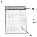
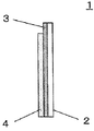
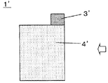
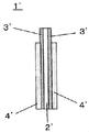
- the electrode plate is not particularly limited by its shape. Examples thereof include a rectangular shape as shown in FIG. 1 and a shape having a notch as shown in FIG.
- the metal tab lead is not particularly limited as long as it is used for an electricity storage device.
- the metal tab lead is preferably made of a metal foil.
- the metal tab lead preferably has a thickness of 0.05 to 1 mm, a width of preferably 5 to 150 mm, and a length of preferably 10 to 100 mm.
- the material used for the metal tab lead is not particularly limited, and examples thereof include metals such as nickel, aluminum, titanium, and copper; alloys such as stainless steel, nickel alloy, aluminum alloy, titanium alloy, and copper alloy.
- the aluminum foil for metal tab lead is preferably subjected to a known annealing treatment.
- the annealing treatment is preferably performed in an inert or reducing atmosphere.
- the treatment temperature is preferably 100 ° C to 500 ° C.
- the treatment time varies depending on the treatment temperature, but is preferably about 1 minute to 1 hour.
- the copper foil for metal tab lead examples include rolled copper foil and electrolytic copper foil. Of these, rolled oxygen-free copper foil is preferable because it is easy to weld and the welded portion has high durability. Further, as the copper foil, a copper foil that has been subjected to rust prevention treatment such as chromate treatment or nickel plating treatment is preferably used.
- the metal tab lead may be composed of a laminate foil in which a metal coating layer is applied to the surface of the metal foil. When the metal coating layer is formed on the surface of the metal foil, a coating layer mainly containing nickel is selected. The thickness of the nickel coating layer is preferably set to 1 to 5 ⁇ m.
- an insulating film is attached to a part of the surface of the metal tab lead.
- the insulating film is preferably made of an olefin polymer.
- the electrode used in the present invention comprises a single metal tab lead and a plurality of electrode plates.
- the plurality of electrode plates constituting the electrode used in the present invention are welded to each other at a portion where the undercoat layer is formed and a portion where the active material layer is not formed, and of the plurality of electrode plates At least one sheet is welded to the metal tab lead at a portion where the undercoat layer is formed and a portion where the active material layer is not formed.
- the portion where the undercoat layer is formed and the portion where the active material layer is not formed (if the undercoat layer is formed in a pattern, it is formed not only in the exposed undercoat layer but also in a pattern.
- the metal foil exposed between the undercoat layers may be referred to as a tab lead weld.
- the plurality of electrode plates in a group are preferably overlapped so that the tab lead welds are arranged at the same position.
- the plurality of electrode plates preferably have substantially the same electrode plate shape and tab lead welded portion shape.
- the pattern shape of the undercoat layer on each surface and the pattern shape of the exposed portion of the undercoat layer are preferably substantially the same. If it does in this way, when it piles up so that the tab lead welding part of an electrode plate may be distribute
- the total thickness of the metal foil is preferably 0.2 to 2 mm, more preferably 0.3 to 1.5 mm, and still more preferably 0.5 to 1.5 mm.
- a power storage device having a large capacity tends to be obtained.
- the total thickness of the metal foil is reduced, the bending stress applied to the tab lead welded portion tends to be within an allowable range when a plurality of electrode plates are combined to be welded to the metal tab lead.
- the plurality of electrode plates for example, are preferably 10 to 100 sheets of metal foil having a thickness of 20 ⁇ m, and preferably 4 to 40 sheets of metal foil having a thickness of 50 ⁇ m.
- a group of a plurality of electrode plates for forming one electrode is alternately stacked one by one with another group of a plurality of electrode plates for forming another one electrode. Furthermore, it is preferable to sandwich a separator between an electrode plate for forming one electrode and an electrode plate for forming another one electrode.
- the electrode plate and the metal tab lead are made to overlap the metal tab lead on the tab lead weld portion of the electrode plate.
- the metal tab lead may overlap the tab lead welded portion of the outermost electrode plate of the plurality of electrode plates, or between the tab lead welded portions of any two adjacent electrode plates among the plurality of electrode plates.
- the metal tab leads may be overlapped with each other.
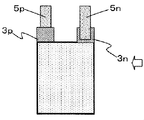
- the electrode plate has a shape as shown in FIGS. 3 and 4
- a plurality of electrode plates P and a plurality of electrode plates N are overlapped as shown in FIGS.
- the metal tab lead 5p can be welded to the tab lead welded portion 3p
- the metal tab lead 5n can be welded to the tab lead welded portion 3n of the electrode plate N.
- a plurality of electrode plates P ′ and a plurality of electrode plates N ′ are overlapped as shown in FIGS. 7 and 8, and the metal tab lead 5p ′ is welded to the tab lead weld portion 3p ′ of the electrode plate P ′.
- the metal tab lead 5n ′ can be welded to the tab lead welding portion 3n ′ of the electrode plate N ′.
- the welding method a known method used for welding metals is selected. Examples thereof include TIG welding, spot welding, laser welding, and ultrasonic welding. Of these, ultrasonic welding is preferred from the viewpoint of welding strength.
- ⁇ ⁇ Welding is performed according to the following procedure.
- the superimposed electrode plates can be placed between an anvil and a horn, a metal tab lead can be placed on the tab lead weld, and ultrasonic waves can be applied to perform one-shot welding.
- One-shot welding means that multiple electrode plates and tab leads are welded together instead of one by one. As long as they are processed together, the application of ultrasonic waves is divided into multiple times. It may be done. It is also possible to weld the electrode plates first and then weld the metal tab lead.
- the degree of welding can be changed by changing the pressure, frequency, output, and processing time during welding. Further, the welding area can be changed by changing the tip shape of the horn.
- Examples of the tip of the horn include a needle shape and a spherical shape. Moreover, the shape which gave the unevenness
- the weld area is the area of the portion that comes into contact with the metal tab lead and is subjected to ultrasonic waves.
- the welding area can be appropriately set according to the shape and area of the tab lead weld. For example, the welding area can be set to preferably 1 to 50%, more preferably 2 to 40% with respect to the single-sided area of the tab lead weld.
- the electrode having the structure as described above can be used as the positive electrode and the negative electrode, and the electrode having the structure as described above can be used as either the positive electrode or the negative electrode. Can do.
- an electrode having the above-described structure can be used for one electrode, and a known electrode can be used for another electrode.
- the separator S is installed between the positive electrode plate and the negative electrode plate.
- a separator what consists of porous insulating materials, such as a nonwoven fabric, a woven fabric, a porous film, is mentioned, for example.
- the porous film include a microporous film made of polyethylene or polypropylene.
- the separator may be provided with a heat resistant layer containing inorganic oxide particles.
- electrolyte a known material used for an electricity storage device such as a lithium ion secondary battery or an electric double layer capacitor can be used.
- the electrolyte for the lithium ion secondary battery include a non-aqueous electrolyte solution, a polymer electrolyte, an inorganic solid electrolyte, and a molten salt electrolyte.
- the non-aqueous electrolyte solution is a solution obtained by dissolving an electrolyte salt in a non-aqueous organic solvent.
- the electrolyte salt include fluorine-containing lithium salts such as lithium hexafluorophosphate (LiPF 6 ) and lithium tetrafluoroborate (LiBF 4 ).
- the non-aqueous organic solvent include ethylene carbonate (EC) and dimethyl carbonate (DMC).
- the polymer electrolyte contains the above electrolyte salt in a polyethylene oxide derivative and a polymer containing the derivative, a polypropylene oxide derivative and a polymer containing the derivative, a phosphate ester polymer, a polycarbonate derivative and a polymer containing the derivative. Can be mentioned.
- inorganic solid electrolytes include those based on sulfide-based glass.
- examples thereof include glass ceramics formed by combining lithium sulfide and at least one selected from the group consisting of silicon sulfide, germanium sulfide, phosphorus sulfide and boron sulfide.
- glass ceramics formed by combining lithium sulfide and phosphorus sulfide are preferably used because of their high ionic conductivity.
- molten salt electrolyte examples include a combination of methylpropylimidazolium bisfluorosulfonylamide and lithium bistrifluoromethanesulfonic acid amide.
- Examples of the electrolyte for the electric double layer capacitor include a water-soluble electrolytic solution and a non-aqueous solvent electrolytic solution.
- Examples of the water-soluble electrolyte include an aqueous sulfuric acid solution, an aqueous sodium sulfate solution, and an aqueous sodium hydroxide solution.
- the nonaqueous solvent electrolyte is a solution obtained by dissolving a cation electrolyte or an anion electrolyte in a nonaqueous solvent.
- Examples of the cation electrolyte include tetraethylammonium salt.
- anionic electrolyte examples include tetrafluoroborate ion (BF 4 ⁇ ) and bistrifluoromethylsulfonylimide ((CF 3 SO 2 ) 2 N ⁇ ).
- non-aqueous solvent examples include ethylene carbonate (EC) and dimethyl carbonate (DMC).
- Exterior material a known exterior material used for an electricity storage device can be selected, and a laminate packaging material is preferable.
- a laminate packaging material is not specifically limited, What has a polymer layer on both sides of aluminum foil is mentioned.
- polyamide or a laminate of polyester on polyamide is used from the viewpoints of heat resistance, puncture strength, lubricity, printability, and the like.
- thermoplastic polyolefin or the like is used as a heat sealant.
- Example 1 ⁇ Preparation of coating solution for undercoat layer> 10 parts by mass of acetylene black (trade name Denka Black (HS-100), manufactured by Denki Kagaku Kogyo Co., Ltd.), 5 parts by mass of dihydroxypropyl chitosan (degree of deacetylation 86 mol%, weight average molecular weight 9.0 ⁇ 10 4 ), 5 parts by mass of pyromellitic anhydride and N-methyl-2-pyrrolidone (industrial grade) were mixed and mixed with a dissolver type stirrer at a rotation speed of 300 rpm for 10 minutes. Subsequently, it processed for 30 seconds at 20000 rpm using the homogenizer (the product name PRO200 by Ieda Trading Co., Ltd.), and obtained the coating liquid for undercoat layers with a solid content concentration of 7 mass%.
- acetylene black trade name Denka Black (HS-100), manufactured by Denki Kagaku Kogyo Co., Ltd.
- undercoat layer coating solution was applied to the entire surface of one side of an aluminum foil (A1N30 material) having a thickness of 20 ⁇ m by a bar coater method. Thereafter, it was heat-treated at 180 ° C. for 3 minutes and dried. Subsequently, the coating was similarly applied to the other side surface to obtain an aluminum foil (hereinafter sometimes referred to as “Al current collecting member”) having an undercoat layer formed on both sides.
- Al current collecting member an aluminum foil having an undercoat layer formed on both sides.
- the basis weight per side of the undercoat layer was 0.5 g / m 2 .
- Measurement of the basis weight per one side was made by cutting out a small thin piece having a size of 100 mm ⁇ 100 mm accurately from an Al current collecting member, and removing one side of the small thin piece from a release agent (manufactured by Sansai Kako Co., Ltd., trade name Neo River # 346). ), The undercoat layer was peeled from one side of the small thin piece, and calculation was performed based on the mass difference before and after peeling.
- Al current collector A small thin piece having a size of 100 mm ⁇ 100 mm (hereinafter sometimes referred to as “Al current collector”) was cut out from the Al current collector member.
- Licobalt oxide Nippon Kagaku Kogyo Co., Ltd., trade name Cellseed C
- acetylene black manufactured by Denki Kagaku Kogyo Co., Ltd., trade name Denka Black (powder product)
- polyvinylidene fluoride A slurry was obtained by mixing 3 parts by mass of Kureha Co., Ltd., trade name KF Polymer # 1120 and 95 parts by mass of N-methyl-2-pyrrolidone (industrial grade).
- the slurry was applied to both surfaces of the Al current collector by the doctor blade method except for an edge having a width of 10 mm and a length of 100 mm from one side of the Al current collector. Then, it was dried and pressed to form positive electrode active material layers each having a width of 90 mm, a length of 100 mm, and a thickness of 50 ⁇ m on both sides of the Al current collector. This was defined as a positive electrode plate P ′′.
- the edge portion having a width of 10 mm ⁇ a length of 100 mm where the undercoat layer was exposed and the positive electrode active material layer was not formed was defined as a tab lead welded portion 3p ′′.
- An electrolytic copper foil of width 100 mm ⁇ length 100 mm ⁇ thickness 10 ⁇ m was prepared.
- the slurry was applied to both surfaces of the electrolytic copper foil by a doctor blade method except for an edge having a width of 10 mm and a length of 100 mm from one side of the electrolytic copper foil. Thereafter, it was dried and pressed to form negative electrode active material layers each having a width of 90 mm, a length of 100 mm, and a thickness of 55 ⁇ m on both surfaces of the electrolytic copper foil. This was designated as the negative electrode plate N ′′.
- a positive electrode tab lead (A1N30-H (aluminum), thickness 0.5 mm, width 20 mm, length 30 mm) 5p ′′ was prepared.
- the tip of the horn was 2 mm ⁇
- the welding area was 24 mm 2 with a 12 mm rectangle.
- a negative electrode tab lead (made of oxygen-free copper, thickness 0.2 mm, width 20 mm, length 30 mm, nickel coating 1 ⁇ m) 5n ′′ was prepared.
- the tip of the horn was a rectangle of 2 mm ⁇ 12 mm.
- the weld area was 24 mm 2 .
- This electrode plate laminate was covered with an aluminum laminate packaging material with the positive electrode tab lead and the negative electrode tab lead protruding from each other, and three sides were sealed to form a bag with one side opened. Water was removed with a vacuum dryer at 60 ° C. Thereafter, a LiPF 6 solution (manufactured by Kishida Chemical Co., Ltd.) was injected as an organic electrolyte, and impregnated for 24 hours in a vacuum atmosphere. A lithium ion secondary battery for evaluation test was manufactured by sealing the opening of the aluminum laminate packaging material with a vacuum sealer.
- the internal resistance of the lithium ion secondary battery for evaluation test was measured by an AC impedance method at a measurement frequency of 1 kHz using an impedance meter (manufactured by Hioki Electric Co., Ltd., model 3532-80). The value of SOC (charged state) 100% was used as the internal resistance value. The results are shown in Table 1 assuming that the internal resistance value after the battery manufacture is “initial value”.
- Example 2 A lithium ion secondary battery was manufactured and evaluated in the same manner as in Example 1 except that the number of positive electrode plates was changed to 30 and the number of negative electrode plates was changed to 31. The results are shown in Table 1.
- Example 3 A lithium ion secondary battery was manufactured and evaluated in the same manner as in Example 1 except that the number of positive electrode plates was changed to 50 and the number of negative electrode plates was changed to 51. The results are shown in Table 1.
- Example 4 A lithium ion secondary battery was manufactured and evaluated in the same manner as in Example 1 except that the number of positive electrode plates was changed to 80 and the number of negative electrode plates was changed to 81. The results are shown in Table 1.
- Example 5 A lithium ion secondary battery was manufactured and evaluated in the same manner as in Example 1 except that the thickness of one aluminum foil was changed to 30 ⁇ m. The results are shown in Table 1.
- Example 6 A lithium ion secondary battery was manufactured and evaluated in the same manner as in Example 1 except that the thickness of one aluminum foil was changed to 50 ⁇ m. The results are shown in Table 1.
- Example 7 A lithium ion secondary battery was produced in the same manner as in Example 1, except that the solid content concentration of the coating liquid for undercoat layer was adjusted and the basis weight per side was changed to 1.2 g / m 2 . Evaluation was performed. The results are shown in Table 1.
- Example 8 A lithium ion secondary battery was produced in the same manner as in Example 1 except that the solid content concentration of the coating liquid for undercoat layer was adjusted to change the basis weight per side to 2.7 g / m 2 . Evaluation was performed. The results are shown in Table 1.
- Example 9 In the production of the positive electrode plate, an aluminum foil (A1N30 material) having a thickness of 20 ⁇ m was used instead of the Al current collector, and in the production of the negative electrode plate, the Cu current collector obtained by the following method was used instead of the electrolytic copper foil.
- a lithium ion secondary battery was manufactured and evaluated in the same manner as in Example 2 except that it was used. The results are shown in Table 1. Note that the measurement of the tab lead welding strength was performed in the same manner as in Example 2 except that the measurement was performed at the portion where the negative electrode tab lead was welded instead of the portion where the positive electrode tab lead was welded.
- the undercoat layer coating solution prepared in Example 1 was applied to the entire surface of one side of an electrolytic copper foil having a thickness of 10 ⁇ m by the bar coater method. Then, it heat-processed for 3 minutes at 180 degreeC, and was made to dry. Subsequently, the coating was similarly applied to the other side, and a copper foil (hereinafter sometimes referred to as a Cu current collecting member) having an undercoat layer formed on both sides was obtained.
- the basis weight per side of the undercoat layer was 0.5 g / m 2 .
- Measurement of the basis weight per side was made by cutting out a small thin piece having a size of 100 mm ⁇ 100 mm accurately from a Cu current collecting member, and removing one side of the small thin piece from a release agent (trade name Neo River # 346, manufactured by Sansai Kako Co., Ltd.). ), The undercoat layer was peeled from one side of the small thin piece, and calculation was performed based on the mass difference before and after peeling. A small thin piece having a size of 100 mm ⁇ 100 mm was cut out from the Cu current collecting member. This small flake was used as a Cu current collector.
- Example 10 A lithium ion secondary battery was manufactured in the same manner as in Example 1, except that in the preparation of the coating solution for the undercoat layer, acetylene black was changed to graphite (manufactured by Timcal Ltd, trade name C-NERGY KS6L). Evaluation was performed. The results are shown in Table 1.
- Example 11 A lithium ion secondary battery was prepared in the same manner as in Example 1, except that acetylene black was changed to carbon nanotubes (trade name VGCF-H, manufactured by Showa Denko KK) in the preparation of the coating solution for the undercoat layer. Manufactured and evaluated. The results are shown in Table 1.
- Comparative Example 1 A lithium ion secondary battery was produced in the same manner as in Example 1 except that the solid content concentration of the coating liquid for the undercoat layer was adjusted to change the basis weight per side to 4.8 g / m 2 . Evaluation was performed. The results are shown in Table 1.
- Comparative Example 2 A lithium ion secondary battery was produced in the same manner as in Example 1 except that the solid content concentration of the coating liquid for undercoat layer was adjusted to change the basis weight per side to 8.9 g / m 2 . Evaluation was performed. The results are shown in Table 1.
- Comparative Example 3 A lithium ion secondary battery was produced and evaluated in the same manner as in Example 1 except that a 20 ⁇ m thick aluminum foil (A1N30 material) was used instead of the Al current collector in the production of the positive electrode plate. . The results are shown in Table 1.
- Example 12 Manufacture of electric double layer capacitors> 100 parts by mass of activated carbon (Kuraray Chemical Co., Ltd., trade name YP-50F), 5 parts by mass of acetylene black (manufactured by Denki Kagaku Kogyo Co., Ltd., trade name Denka Black (powder)), styrene butadiene rubber (Nippon A & L) A paste prepared by mixing 7.5 parts by mass of trade name Nalstar SR-103 manufactured by Co., Ltd., 2 parts by mass of carboxymethylcellulose (manufactured by Daicel Finechem Co., Ltd., trade name CMC DN-10L), and 200 parts by mass of pure water Got.
- activated carbon Karl Chemical Co., Ltd., trade name YP-50F
- acetylene black manufactured by Denki Kagaku Kogyo Co., Ltd., trade name Denka Black (powder)
- styrene butadiene rubber Nippon A & L
- the paste was applied to both surfaces of the Al current collector by the doctor blade method except for an edge having a width of 10 mm and a length of 100 mm from one side of the Al current collector. Thereafter, drying and pressing were performed to form electrode layers (active material layers) each having a width of 90 mm, a length of 100 mm, and a thickness of 80 ⁇ m on both sides of the Al current collector. This was used as an electrode plate for an electric double layer capacitor. An edge portion having a width of 10 mm and a length of 100 mm, in which the undercoat layer was exposed and the electrode layer was not formed, was defined as a tab lead welded portion.
- Electrode plates were prepared, 15 as positive electrodes, 16 as negative electrodes, and alternately stacked one by one as shown in FIG. 9, and a separator (Nippon Advanced Paper Industries) between the positive electrode plates and the negative electrode plates. (Product name, TF40) was inserted to obtain an electrode plate laminate in which the negative electrode plate was the outermost layer.
- TF40 Nippon Advanced Paper Industries
- two aluminum tab leads (A1N30-H, thickness 0.5 mm, width 20 mm, length 30 mm) were prepared.
- One aluminum tab lead (positive electrode tab lead) and 15 tab lead welded portions of the positive electrode plate of the electrode plate laminate were joined by an ultrasonic welding machine. Welding was performed under the conditions of a horn tip angle of 90 degrees, a pressure of 0.3 MPa, a frequency of 20 kHz, and 0.3 seconds. The tip of the horn was a 2 mm ⁇ 12 mm rectangle, and the welding area was 24 mm 2 .
- Another aluminum tab lead (negative electrode tab lead) and 16 tab lead welds of the negative electrode plate of the electrode plate laminate were joined with an ultrasonic welder.
- Welding was performed under the conditions of a horn tip angle of 90 degrees, a pressure of 0.3 MPa, a frequency of 20 kHz, and 0.3 seconds.
- the tip of the horn was a 2 mm ⁇ 12 mm rectangle, and the welding area was 24 mm 2 .
- the obtained electrode plate laminate was covered with an aluminum laminate packaging material with the positive electrode tab lead and the negative electrode tab lead protruding from each other, and three sides were sealed to form a bag with one side opened. Water was removed with a vacuum dryer at 60 ° C. Thereafter, an organic electrolyte (trade name LIPASTE-P / EAFIN (1 mol / liter) manufactured by Toyama Pharmaceutical Co., Ltd.) was poured and impregnated in a vacuum atmosphere for 24 hours. The opening of the aluminum laminate packaging material was sealed with a vacuum sealer to produce an electric double layer capacitor for evaluation tests.
- the internal resistance of the electric double layer capacitor for evaluation test was measured by an AC impedance method at a measurement frequency of 1 kHz using an impedance meter (manufactured by Hioki Electric Co., Ltd., model 3532-80).
- the value of the state of SOC (charged state) 100% was used as the internal resistance.
- Table 2 The results are shown in Table 2 with the internal resistance value after manufacturing the capacitor as the “initial value”.
- Example 13 An electric double layer capacitor was manufactured and evaluated in the same manner as in Example 12, except that the solid content concentration of the coating liquid for the undercoat layer was adjusted to change the basis weight per side to 1.2 g / m 2. Went. The results are shown in Table 2.
- Example 14 An electric double layer capacitor was manufactured and evaluated in the same manner as in Example 12 except that the solid content concentration of the coating liquid for undercoat layer was adjusted to change the basis weight per side to 2.7 g / m 2. Went. The results are shown in Table 2.
- Comparative Example 4 An electric double layer capacitor was manufactured and evaluated in the same manner as in Example 12 except that the solid content concentration of the coating liquid for the undercoat layer was adjusted to change the basis weight per side to 4.8 g / m 2. Went. The results are shown in Table 2.
- Comparative Example 5 An electric double layer capacitor was manufactured and evaluated in the same manner as in Example 12 except that the solid content concentration of the coating liquid for undercoat layer was adjusted to change the basis weight per side to 8.9 g / m 2. Went. The results are shown in Table 2.
- Electrode plate 2' Metal foil 3
- 3 ' Undercoat layer 4
Abstract
Description
本発明の目的は、一枚の金属タブリードと複数枚の電極板とが溶接されてなる電極を含む蓄電デバイスを高い生産性にて製造する方法を提供することである。 In order to make a high-capacity battery, a plurality of positive electrode plates and negative electrode plates may be used in an overlapping manner. Even in an electric double layer capacitor, a plurality of electrode plates may be used in an overlapping manner in order to increase the capacity. When a plurality of electrode plates are used, the problem related to the formation of the current collector exposed portion as described above becomes greater.
An object of the present invention is to provide a method for manufacturing an electricity storage device including an electrode formed by welding a single metal tab lead and a plurality of electrode plates with high productivity.
〔1〕 一枚の金属タブリードと複数枚の電極板とからなる電極を少なくとも一つ有する蓄電デバイスであって、
電極板が、金属箔と、金属箔の片面または両面に形成されたアンダーコート層と、アンダーコート層が形成されている部分の一部表面に形成された活物質層とを有し、
アンダーコート層は炭素材料を含み且つ片面あたりの目付量が0.05~3g/m2であり、
複数枚の電極板はアンダーコート層が形成されている部分で且つ活物質層が形成されていない部分にて互いに溶接され、且つ
複数枚の電極板のうちの少なくとも1枚はアンダーコート層が形成されている部分で且つ活物質層が形成されていない部分にて金属タブリードと溶接されている、
蓄電デバイス。
〔2〕 複数枚の電極板の金属箔の厚さの合計が0.2~2mmである、〔1〕に記載の蓄電デバイス。
〔3〕 アンダーコート層は、炭素材料1~60質量%を含む、〔1〕または〔2〕に記載の蓄電デバイス。 That is, the present invention includes the following aspects.
[1] An electricity storage device having at least one electrode composed of one metal tab lead and a plurality of electrode plates,
The electrode plate has a metal foil, an undercoat layer formed on one or both sides of the metal foil, and an active material layer formed on a part of the surface where the undercoat layer is formed,
The undercoat layer contains a carbon material and the basis weight per side is 0.05 to 3 g / m 2 .
The plurality of electrode plates are welded to each other at the portion where the undercoat layer is formed and the portion where the active material layer is not formed, and at least one of the plurality of electrode plates forms an undercoat layer Is welded to the metal tab lead at the portion where the active material layer is not formed.
Power storage device.
[2] The electricity storage device according to [1], wherein the total thickness of the metal foils of the plurality of electrode plates is 0.2 to 2 mm.
[3] The electricity storage device according to [1] or [2], wherein the undercoat layer contains 1 to 60% by mass of a carbon material.
〔5〕 結着材が、キトサンまたはその誘導体である〔4〕に記載の蓄電デバイス。
〔6〕 活物質層の面積が、アンダーコート層が形成されている部分の面積の80~99面積%である、〔1〕~〔5〕のいずれか1項に記載の蓄電デバイス。
〔7〕 金属タブリードが、アルミニウム、銅およびニッケルからなる群より選ばれる少なくとも一つを含むものである、〔1〕~〔6〕のいずれかひとつに記載の蓄電デバイス。 [4] The electricity storage device according to any one of [1] to [3], wherein the undercoat layer includes 20 to 300 parts by mass of a binder with respect to 100 parts by mass of the carbon material.
[5] The electricity storage device according to [4], wherein the binder is chitosan or a derivative thereof.
[6] The electricity storage device according to any one of [1] to [5], wherein the area of the active material layer is 80 to 99 area% of the area of the portion where the undercoat layer is formed.
[7] The electricity storage device according to any one of [1] to [6], wherein the metal tab lead includes at least one selected from the group consisting of aluminum, copper, and nickel.
〔9〕 金属箔の1枚の厚さが5~70μmである、〔1〕~〔8〕のいずれかひとつに記載の蓄電デバイス。
〔10〕 炭素材料は、黒鉛、導電性カーボンブラック、カーボンナノチューブおよびカーボンナノファイバーからなる群より選ばれる少なくとも一つを含むものである、〔1〕~〔9〕のいずれかひとつに記載の蓄電デバイス。
〔11〕 リチウムイオン電池である、〔1〕~〔10〕のいずれかひとつに記載の蓄電デバイス。 [8] The electricity storage device according to any one of [1] to [7], wherein the metal foil is an aluminum foil or a copper foil.
[9] The electricity storage device according to any one of [1] to [8], wherein the thickness of one metal foil is 5 to 70 μm.
[10] The electricity storage device according to any one of [1] to [9], wherein the carbon material includes at least one selected from the group consisting of graphite, conductive carbon black, carbon nanotubes, and carbon nanofibers.
[11] The electricity storage device according to any one of [1] to [10], which is a lithium ion battery.
複数枚の電極板をアンダーコート層が形成されている部分で且つ活物質層が形成されていない部分にて互いに溶接し、且つ複数枚の電極板のうちの少なくとも1枚をアンダーコート層が形成されている部分で且つ活物質層が形成されていない部分にて金属タブリードと溶接する工程
を含む〔1〕~〔11〕のいずれかひとつに記載の蓄電デバイスの製造方法。
〔13〕 溶接する工程がワンショット溶接で行われる、〔12〕に記載の製造方法。
〔14〕 溶接する工程が超音波溶接で行われる、〔12〕または〔13〕に記載の製造方法。 [12] A plurality of electrode plates having a metal foil, an undercoat layer formed on one or both sides of the metal foil, and an active material layer formed on a part of the surface where the undercoat layer is formed A step of preparing, and welding a plurality of electrode plates to each other at a portion where an undercoat layer is formed and a portion where an active material layer is not formed, and at least one of the plurality of electrode plates The method for manufacturing an electricity storage device according to any one of [1] to [11], including a step of welding to a metal tab lead at a portion where the undercoat layer is formed and a portion where the active material layer is not formed.
[13] The manufacturing method according to [12], wherein the step of welding is performed by one-shot welding.
[14] The production method according to [12] or [13], wherein the welding step is performed by ultrasonic welding.
本発明の一実施形態に係る蓄電デバイスは、一枚の金属タブリードと複数枚の電極板とからなる電極を少なくとも一つ有するものである。蓄電デバイスとしては、例えば、リチウムイオン二次電池、電気二重層キャパシタなどが挙げられる。これらのうち、本発明に係る蓄電デバイスはリチウムイオン二次電池に好適である。一般的に、一の電極中に在る複数枚の電極板は、他の一の電極中の複数枚の電極板と、一枚づつ互い違いに重ねて、蓄電デバイスの外装内に収納される。 [Power storage device]
An electricity storage device according to an embodiment of the present invention has at least one electrode composed of one metal tab lead and a plurality of electrode plates. Examples of the electricity storage device include a lithium ion secondary battery and an electric double layer capacitor. Among these, the electricity storage device according to the present invention is suitable for a lithium ion secondary battery. In general, a plurality of electrode plates in one electrode are housed in an exterior of an electricity storage device, alternately stacked one by one with a plurality of electrode plates in another one electrode.
一枚の電極板は、金属箔と、金属箔の片面または両面に形成されたアンダーコート層と、アンダーコート層が形成されている部分の一部表面に形成された活物質層とを有するものである。 <Electrode plate>
One electrode plate has a metal foil, an undercoat layer formed on one or both sides of the metal foil, and an active material layer formed on a part of the surface where the undercoat layer is formed. It is.
本発明に用いられる金属箔は、従来の蓄電デバイスにおいて用いられている公知のものである。金属箔に用いられる材料は、特に制限されず、例えば、ニッケル、アルミニウム、チタン、銅などの金属;ステンレス、ニッケル合金、アルミニウム合金、チタン合金、銅合金などの合金などが挙げられる。 (Metal foil)
The metal foil used for this invention is a well-known thing used in the conventional electrical storage device. The material used for the metal foil is not particularly limited, and examples thereof include metals such as nickel, aluminum, titanium, and copper; alloys such as stainless steel, nickel alloy, aluminum alloy, titanium alloy, and copper alloy.
金属箔の面積は、蓄電デバイスの用途に応じて適宜設定することができる。例えば、電気自動車用電源として用いる場合は、金属箔一枚の面積は、好ましくは5000mm2~1000000mm2、より好ましくは8000mm2~500000mm2である。 From the viewpoint of easy handling of the metal foil or electrode plate and miniaturization of the electricity storage device, the thickness of each metal foil is preferably 5 μm to 70 μm, more preferably 5 μm to 50 μm.
The area of the metal foil can be appropriately set according to the use of the electricity storage device. For example, when used as a power source for electric vehicles, the area of one metal foil is preferably 5000mm 2 ~ 1000000mm 2, more preferably 8000mm 2 ~ 500000mm 2.
アンダーコート層は、金属箔の片面または両面に、好ましくは金属箔の片面または両面に接して形成される。アンダーコート層は、金属箔の一部表面に形成されていてもよいし、全面に形成されていてもよい。金属箔の主面のみならず、端面にも形成されていてもよい。金属箔の一部表面にアンダーコート層を形成する態様としては、金属箔表面のうちの所定の範囲にのみアンダーコート層を形成する態様、金属箔全面にドットパターン、ラインアンドスペースパターンなどのパターン状にアンダーコート層を形成する態様などがある。 (Undercoat layer)
The undercoat layer is formed on one side or both sides of the metal foil, preferably in contact with one side or both sides of the metal foil. The undercoat layer may be formed on a part of the surface of the metal foil, or may be formed on the entire surface. It may be formed not only on the main surface of the metal foil but also on the end surface. As an aspect of forming the undercoat layer on a part of the surface of the metal foil, an aspect in which the undercoat layer is formed only in a predetermined range on the surface of the metal foil, a pattern such as a dot pattern or a line and space pattern on the entire surface of the metal foil For example, an undercoat layer may be formed.
目付量を多くしたい場合は、固形分濃度を高くしたり、クリアランスを大きくしたりする。目付量を少なくしたい場合は、固形分濃度を低くしたり、クリアランスを小さくしたりする。また、所望の目付量になるまで複数回塗工を繰り返してもよい。 The basis weight can be adjusted by a known method. For example, when the undercoat layer is formed by coating, it can be adjusted by the solid content concentration of the coating liquid for forming the undercoat layer, the clearance of the coating liquid inlet of the coating machine, or the like.
In order to increase the basis weight, the solid content concentration is increased or the clearance is increased. When it is desired to reduce the basis weight, the solid content concentration is lowered or the clearance is reduced. Further, the coating may be repeated a plurality of times until a desired basis weight is obtained.
アンダーコート層中の他の材料や、前述の金属箔あるいは後述の活物質層との結着性が良好になるように、炭素材料の粒径を選定することができる。
アンダーコート層中に含まれる炭素材料の量は、好ましくは1~60質量%、より好ましくは20~50質量%である。このような量で炭素材料が含まれていると、アンダーコート層の導電性が向上し、金属箔と活物質層との間の電気抵抗が低下する。 The carbon material may be completely buried in the undercoat layer, or may be fixed in a state of being partially exposed from the undercoat layer. As long as conductivity is imparted to the undercoat layer, the dispersion state of the carbon material in the undercoat layer is not particularly limited. Further, it is preferable that the carbon material does not fall off from the undercoat layer.
The particle size of the carbon material can be selected so that the binding properties with other materials in the undercoat layer, the above-described metal foil or the active material layer described later are improved.
The amount of the carbon material contained in the undercoat layer is preferably 1 to 60% by mass, more preferably 20 to 50% by mass. When the carbon material is contained in such an amount, the conductivity of the undercoat layer is improved, and the electrical resistance between the metal foil and the active material layer is lowered.
塗布法によるアンダーコート層の形成は、アンダーコート層を構成する各成分またはその前駆体を含む塗工液を調製し、該塗工液を金属箔に塗布し、乾燥することを含む。 Examples of the method for forming the undercoat layer on the metal foil include vapor phase methods such as sputtering, vapor deposition, and chemical vapor deposition, and coating methods such as dipping and printing. Among these, the coating method is preferable from the viewpoint that it can be continuously processed by a roll-to-roll method and the cost can be reduced.
Formation of the undercoat layer by the coating method includes preparing a coating liquid containing each component constituting the undercoat layer or a precursor thereof, applying the coating liquid to a metal foil, and drying.
活物質層は、アンダーコート層が形成されている部分の一部表面に、好ましくはアンダーコート層が形成されている部分の一部表面に接して形成される。ここで、「アンダーコート層が形成されている部分」は、金属箔表面に正に形成されているアンダーコート層の部分だけでなく、パターン状に形成されたアンダーコート層の間に露出する金属箔の部分も含む。活物質層は、アンダーコート層が形成されている部分の一部が露出するように、好ましくはアンダーコート層が形成されている部分の縁部分が露出するように、形成させる。活物質層の面積は、アンダーコート層が形成されている部分の面積(アンダーコート層がパターン状に形成させられている場合は、正に形成されているアンダーコート層の面積とパターン状に形成されたアンダーコート層の間に露出する金属箔の面積との合計である。)の、好ましくは80~99面積%、より好ましくは90~95面積%である。両面に活物質層を形成させる場合は、アンダーコート層が形成されている部分で且つ活物質層が形成されていない部分を、両面の同じ位置に設けることが好ましい。アンダーコート層が形成されている部分で且つ活物質層が形成されていない部分は、その形状において特に限定されない。 (Active material layer)
The active material layer is formed on a partial surface of a portion where the undercoat layer is formed, preferably in contact with a partial surface of the portion where the undercoat layer is formed. Here, “the portion where the undercoat layer is formed” means not only the portion of the undercoat layer that is positively formed on the surface of the metal foil but also the metal exposed between the undercoat layers formed in a pattern. Including the foil part. The active material layer is formed so that a part of the part where the undercoat layer is formed is exposed, and preferably the edge part of the part where the undercoat layer is formed is exposed. The area of the active material layer is the area of the portion where the undercoat layer is formed (if the undercoat layer is formed in a pattern, it is formed in the pattern with the area of the positively formed undercoat layer. The total area of the exposed metal foil between the undercoat layers is preferably 80 to 99 area%, more preferably 90 to 95 area%. When forming an active material layer on both surfaces, it is preferable to provide a portion where an undercoat layer is formed and a portion where no active material layer is formed at the same position on both surfaces. The portion where the undercoat layer is formed and the portion where the active material layer is not formed is not particularly limited in its shape.
リチウムイオン二次電池の充電時には、正極活物質に保持されていたリチウムイオンが脱インターカレートして電解液中に放出され、負極活物質である炭素材料の結晶層間に、電解液中のリチウムイオンが吸蔵されることで進行する。また放電時には、充電時とは逆に、リチウムイオンが負極活物質から放出され、正極活物質に吸蔵されることで進行する。 In the active material layer used for the negative electrode of the lithium ion secondary battery, as the active material, for example, carbon materials such as artificial graphite and natural graphite; metal materials such as Sn and Si or metalloid materials; lithium titanate, titanium oxide, and the like Metal oxides can be used.
At the time of charging the lithium ion secondary battery, lithium ions held in the positive electrode active material are deintercalated and released into the electrolytic solution, and the lithium in the electrolytic solution is interposed between the crystal layers of the carbon material that is the negative electrode active material. It progresses as ions are occluded. In discharging, lithium ions are released from the negative electrode active material and stored in the positive electrode active material, contrary to charging.
電気二重層キャパシタは、リチウムイオン二次電池のようなファラデー反応による蓄電システムではない。電気二重層キャパシタは、電解液中の陽イオンと陰イオンのそれぞれが電極中の活物質表面に電気二重層を形成する物理現象を利用した蓄電システムである。 In the active material layer used for the electrode of the electric double layer capacitor, for example, activated carbon can be used as the active material. Examples of the activated carbon include coconut shell activated carbon and fibrous activated carbon. The activated carbon is not particularly limited by the activation method, and those obtained by a water vapor activation method or a chemical activation method can be employed. In order to obtain a high-capacity capacitor, an alkali activated carbon, that is, an alkali activated charcoal is preferable.
The electric double layer capacitor is not a power storage system based on a Faraday reaction like a lithium ion secondary battery. An electric double layer capacitor is a power storage system using a physical phenomenon in which each of a cation and an anion in an electrolytic solution forms an electric double layer on the surface of an active material in an electrode.
リチウムイオン二次電池や電気二重層キャパシタの電極に用いる活物質層では、結着剤として、例えば、ポリエチレン、ポリプロピレン、エチレンプロピレンコポリマー、エチレンプロピレンターポリマー、ブタジエンゴム、スチレンブタジエンゴム、ブチルゴム、ポリテトラフルオロエチレン、ポリ(メタ)アクリレート、ポリフッ化ビニリデン、ポリエチレンオキサイド、ポリプロピレンオキサイド、ポリエピクロルヒドリン、ポリフォスファゼン、ポリアクリロニトリルなどを用いることができる。 In an active material layer used for an electrode of a lithium ion secondary battery or an electric double layer capacitor, for example, conductive carbon black such as acetylene black, ketjen black and furnace black; graphite such as artificial graphite and natural graphite Carbon fibers, vapor grown carbon fibers, carbon nanotubes, carbon nanofibers, and the like can be used.
In an active material layer used for an electrode of a lithium ion secondary battery or an electric double layer capacitor, as a binder, for example, polyethylene, polypropylene, ethylene propylene copolymer, ethylene propylene terpolymer, butadiene rubber, styrene butadiene rubber, butyl rubber, polytetra Fluoroethylene, poly (meth) acrylate, polyvinylidene fluoride, polyethylene oxide, polypropylene oxide, polyepichlorohydrin, polyphosphazene, polyacrylonitrile, and the like can be used.
金属タブリードは、蓄電デバイスに使用されるものであれば、特に制限されない。金属タブリードは、好ましくは金属箔で構成される。金属タブリードは、厚さが好ましくは0.05~1mm、幅が好ましくは5~150mm、長さが好ましくは10~100mmである。金属タブリードに用いられる材料は、特に制限されず、例えば、ニッケル、アルミニウム、チタン、銅などの金属;ステンレス、ニッケル合金、アルミニウム合金、チタン合金、銅合金などの合金などが挙げられる。金属タブリード用のアルミニウム箔は、公知の焼き鈍し処理を施したものであることが好ましい。焼き鈍し処理は、不活性又は還元性雰囲気中で行うことが好ましい。処理温度は、好ましくは100℃~500℃である。処理時間は、処理温度によっても異なるが、好ましくは1分間~1時間程度である。 <Metal tab lead>
The metal tab lead is not particularly limited as long as it is used for an electricity storage device. The metal tab lead is preferably made of a metal foil. The metal tab lead preferably has a thickness of 0.05 to 1 mm, a width of preferably 5 to 150 mm, and a length of preferably 10 to 100 mm. The material used for the metal tab lead is not particularly limited, and examples thereof include metals such as nickel, aluminum, titanium, and copper; alloys such as stainless steel, nickel alloy, aluminum alloy, titanium alloy, and copper alloy. The aluminum foil for metal tab lead is preferably subjected to a known annealing treatment. The annealing treatment is preferably performed in an inert or reducing atmosphere. The treatment temperature is preferably 100 ° C to 500 ° C. The treatment time varies depending on the treatment temperature, but is preferably about 1 minute to 1 hour.
金属タブリードは、金属箔表面に金属被覆層が施された積層体箔で構成されていてもよい。金属箔表面に金属被覆層を形成させる場合、主にニッケルを含有する被覆層が選ばれる。ニッケル被覆層の厚さは1~5μmに設定されるのが好ましい。 Examples of the copper foil for metal tab lead include rolled copper foil and electrolytic copper foil. Of these, rolled oxygen-free copper foil is preferable because it is easy to weld and the welded portion has high durability. Further, as the copper foil, a copper foil that has been subjected to rust prevention treatment such as chromate treatment or nickel plating treatment is preferably used.
The metal tab lead may be composed of a laminate foil in which a metal coating layer is applied to the surface of the metal foil. When the metal coating layer is formed on the surface of the metal foil, a coating layer mainly containing nickel is selected. The thickness of the nickel coating layer is preferably set to 1 to 5 μm.
本発明に用いられる電極は、一枚の金属タブリードと複数枚の電極板とからなるものである。本発明に用いられる電極を構成する複数枚の電極板はアンダーコート層が形成されている部分で且つ活物質層が形成されていない部分にて互いに溶接され、かつ複数枚の電極板のうちの少なくとも1枚はアンダーコート層が形成されている部分で且つ活物質層が形成されていない部分にて金属タブリードと溶接されている。アンダーコート層が形成されている部分で且つ活物質層が形成されていない部分(アンダーコート層がパターン状に形成されている場合、露出するアンダーコート層の部分だけでなく、パターン状に形成されたアンダーコート層の間に露出する金属箔も含む)を、以下、タブリード溶接部と呼ぶことがある。 〔electrode〕
The electrode used in the present invention comprises a single metal tab lead and a plurality of electrode plates. The plurality of electrode plates constituting the electrode used in the present invention are welded to each other at a portion where the undercoat layer is formed and a portion where the active material layer is not formed, and of the plurality of electrode plates At least one sheet is welded to the metal tab lead at a portion where the undercoat layer is formed and a portion where the active material layer is not formed. The portion where the undercoat layer is formed and the portion where the active material layer is not formed (if the undercoat layer is formed in a pattern, it is formed not only in the exposed undercoat layer but also in a pattern. Hereinafter, the metal foil exposed between the undercoat layers may be referred to as a tab lead weld.
該複数枚の電極板は、電極板の形状や、タブリード溶接部の形状が、略同一であることが好ましい。また、金属箔の両面にアンダーコート層および活物質層が形成されている複数枚の電極板においては、それぞれの面のアンダーコート層のパターン形状およびアンダーコート層の露出している箇所のパターン形状が略同一であることが好ましい。このようにすると、電極板のタブリード溶接部が同じ位置に配されるように重ね合わせたときに、電極板の縁が揃い、蓄電デバイスの体積を小さくすることができる。 The plurality of electrode plates in a group are preferably overlapped so that the tab lead welds are arranged at the same position.
The plurality of electrode plates preferably have substantially the same electrode plate shape and tab lead welded portion shape. In addition, in a plurality of electrode plates in which the undercoat layer and the active material layer are formed on both surfaces of the metal foil, the pattern shape of the undercoat layer on each surface and the pattern shape of the exposed portion of the undercoat layer Are preferably substantially the same. If it does in this way, when it piles up so that the tab lead welding part of an electrode plate may be distribute | arranged to the same position, the edge of an electrode plate will align and the volume of an electrical storage device can be made small.
また電極板と金属タブリードは、電極板のタブリード溶接部に金属タブリードを重ねるようにする。金属タブリードは、複数枚の電極板の最も外側の電極板のタブリード溶接部に重ね合わせてもよいし、該複数枚の電極板のうち、任意の隣接する2枚の電極板のタブリード溶接部間に金属タブリードを挟むようにして重ね合わせてもよい。 It is preferable that a group of a plurality of electrode plates for forming one electrode is alternately stacked one by one with another group of a plurality of electrode plates for forming another one electrode. Furthermore, it is preferable to sandwich a separator between an electrode plate for forming one electrode and an electrode plate for forming another one electrode.
The electrode plate and the metal tab lead are made to overlap the metal tab lead on the tab lead weld portion of the electrode plate. The metal tab lead may overlap the tab lead welded portion of the outermost electrode plate of the plurality of electrode plates, or between the tab lead welded portions of any two adjacent electrode plates among the plurality of electrode plates. The metal tab leads may be overlapped with each other.
短絡を防止するために正極電極板と負極電極板との間にセパレータSが設置される。セパレータとしては、例えば、不織布、織布、多孔質フィルムなどの多孔質絶縁性材料から成るものが挙げられる。多孔質フィルムの例としては、ポリエチレンやポリプロピレン製のマイクロポーラスフィルムなどが挙げられる。またセパレータには、無機酸化物粒子を含む耐熱層が設けられていてもよい。 (Separator)
In order to prevent a short circuit, the separator S is installed between the positive electrode plate and the negative electrode plate. As a separator, what consists of porous insulating materials, such as a nonwoven fabric, a woven fabric, a porous film, is mentioned, for example. Examples of the porous film include a microporous film made of polyethylene or polypropylene. The separator may be provided with a heat resistant layer containing inorganic oxide particles.
電解質として、リチウムイオン二次電池や電気二重層キャパシタなどの蓄電デバイスに使用されている公知の材料を用いることが可能である。
リチウムイオン二次電池用の電解質としては、例えば、非水電解質液、ポリマー電解質、無機固体電解質、溶融塩電解質などを挙げることができる。 (Electrolytes)
As the electrolyte, a known material used for an electricity storage device such as a lithium ion secondary battery or an electric double layer capacitor can be used.
Examples of the electrolyte for the lithium ion secondary battery include a non-aqueous electrolyte solution, a polymer electrolyte, an inorganic solid electrolyte, and a molten salt electrolyte.
外装材は蓄電デバイスに使用されている公知の外装材を選ぶことができ、好ましくはラミネート包材である。ラミネート包材の構成は特に限定されないが、アルミニウム箔の両側にポリマー層を有するものが挙げられる。例えば、蓄電デバイスの外側になるポリマー層には、耐熱性、突き刺し強度、滑性、印刷性などの観点からポリアミドや、ポリアミドにポリエステルを積層したものなどが用いられる。内側のポリマー層には、ヒートシーラントとして熱可塑性ポリオレフィンなどが用いられる。 (Exterior material)
As the exterior material, a known exterior material used for an electricity storage device can be selected, and a laminate packaging material is preferable. Although the structure of a laminate packaging material is not specifically limited, What has a polymer layer on both sides of aluminum foil is mentioned. For example, for the polymer layer on the outside of the electricity storage device, polyamide or a laminate of polyester on polyamide is used from the viewpoints of heat resistance, puncture strength, lubricity, printability, and the like. For the inner polymer layer, thermoplastic polyolefin or the like is used as a heat sealant.
<アンダーコート層用の塗工液の調製>
アセチレンブラック(電気化学工業(株)製、商品名デンカブラック(HS-100))10質量部、ジヒドロキシプロピルキトサン(脱アセチル化度86mol%、重量平均分子量9.0×10⁴)5質量部、無水ピロメリット酸5質量部、およびN-メチル-2-ピロリドン(工業用グレード)を混合し、ディゾルバータイプの撹拌機にて回転数300rpmで10分間混ぜ合わせた。次いで、ホモジナイザー(家田貿易(株)製、製品名PRO200)を用いて20000rpmで30秒間処理し、固形分濃度7質量%のアンダーコート層用塗工液を得た。 Example 1
<Preparation of coating solution for undercoat layer>
10 parts by mass of acetylene black (trade name Denka Black (HS-100), manufactured by Denki Kagaku Kogyo Co., Ltd.), 5 parts by mass of dihydroxypropyl chitosan (degree of deacetylation 86 mol%, weight average molecular weight 9.0 × 10 4 ), 5 parts by mass of pyromellitic anhydride and N-methyl-2-pyrrolidone (industrial grade) were mixed and mixed with a dissolver type stirrer at a rotation speed of 300 rpm for 10 minutes. Subsequently, it processed for 30 seconds at 20000 rpm using the homogenizer (the product name PRO200 by Ieda Trading Co., Ltd.), and obtained the coating liquid for undercoat layers with a solid content concentration of 7 mass%.
厚さ20μmのアルミニウム箔(A1N30材)の片面全面に、アンダーコート層用塗工液をバーコーター法によって塗工した。その後、180℃にて3分間熱処理し乾燥させた。次いで別の片面にも同様に塗工し、両面にアンダーコート層が形成されたアルミニウム箔(以下、Al集電部材ということがある。)を得た。アンダーコート層の片面あたりの目付量は0.5g/m2であった。片面あたりの目付量の測定は、Al集電部材から正確に100mm×100mmの大きさの小薄片を切り出し、該小薄片の片面を剥離剤(三彩化工(株)製、商品名ネオリバー#346)で処理して、小薄片の片面からアンダーコート層を剥離し、剥離前後の質量差に基づいて算出した。 <Formation of undercoat layer>
An undercoat layer coating solution was applied to the entire surface of one side of an aluminum foil (A1N30 material) having a thickness of 20 μm by a bar coater method. Thereafter, it was heat-treated at 180 ° C. for 3 minutes and dried. Subsequently, the coating was similarly applied to the other side surface to obtain an aluminum foil (hereinafter sometimes referred to as “Al current collecting member”) having an undercoat layer formed on both sides. The basis weight per side of the undercoat layer was 0.5 g / m 2 . Measurement of the basis weight per one side was made by cutting out a small thin piece having a size of 100 mm × 100 mm accurately from an Al current collecting member, and removing one side of the small thin piece from a release agent (manufactured by Sansai Kako Co., Ltd., trade name Neo River # 346). ), The undercoat layer was peeled from one side of the small thin piece, and calculation was performed based on the mass difference before and after peeling.
Al集電部材から100mm×100mmの大きさの小薄片(以下、Al集電体ということがある。)を切り出した。
コバルト酸リチウム(日本化学工業(株)製、商品名セルシードC)95質量部、アセチレンブラック(電気化学工業(株)製、商品名デンカブラック(粉状品))2質量部、ポリフッ化ビニリデン((株)クレハ製、商品名KFポリマー#1120)3質量部、およびN-メチル-2-ピロリドン(工業用グレード)95質量部を混合してスラリーを得た。
Al集電体の一辺から幅10mm×長さ100mmの縁部を除いて、Al集電体の両面にドクターブレード法にて前記スラリーを塗布した。その後、乾燥させ、プレスして幅90mm×長さ100mm×厚さ50μmの正極活物質層をAl集電体の両面にそれぞれ形成させた。これを正極電極板P”とした。アンダーコート層が露出し、正極活物質層を形成させなかった、幅10mm×長さ100mmの縁部をタブリード溶接部3p”とした。 <Manufacture of positive electrode plate>
A small thin piece having a size of 100 mm × 100 mm (hereinafter sometimes referred to as “Al current collector”) was cut out from the Al current collector member.
95 parts by mass of lithium cobalt oxide (Nippon Kagaku Kogyo Co., Ltd., trade name Cellseed C), 2 parts by mass of acetylene black (manufactured by Denki Kagaku Kogyo Co., Ltd., trade name Denka Black (powder product)), polyvinylidene fluoride ( A slurry was obtained by mixing 3 parts by mass of Kureha Co., Ltd., trade name KF Polymer # 1120 and 95 parts by mass of N-methyl-2-pyrrolidone (industrial grade).
The slurry was applied to both surfaces of the Al current collector by the doctor blade method except for an edge having a width of 10 mm and a length of 100 mm from one side of the Al current collector. Then, it was dried and pressed to form positive electrode active material layers each having a width of 90 mm, a length of 100 mm, and a thickness of 50 μm on both sides of the Al current collector. This was defined as a positive electrode plate P ″. The edge portion having a width of 10 mm × a length of 100 mm where the undercoat layer was exposed and the positive electrode active material layer was not formed was defined as a tab lead welded
人造黒鉛(昭和電工(株)製、商品名SCMG-AR)94質量部、アセチレンブラック(電気化学工業(株)製、商品名デンカブラック(粉状品))1質量部、ポリフッ化ビニリデン((株)クレハ製、商品名KFポリマー#9130)5質量部、およびN-メチル-2-ピロリドン(工業用グレード)94質量部を混合してスラリーを得た。
幅100mm×長さ100mm×厚さ10μmの電解銅箔を用意した。
電解銅箔の一辺から幅10mm×長さ100mmの縁部を除いて、電解銅箔の両面にドクターブレード法にてスラリーを塗布した。その後、乾燥させ、プレスして幅90mm×長さ100mm×厚さ55μmの負極活物質層を電解銅箔の両面にそれぞれ形成させた。これを負極電極板N”とした。銅箔が露出し、負極活物質層を形成させなかった、幅10mm×長さ100mmの縁部をタブリード溶接部3n”とした。 <Manufacture of negative electrode plate>
94 parts by mass of artificial graphite (made by Showa Denko KK, trade name SCMG-AR), 1 part by weight of acetylene black (made by Denki Kagaku Kogyo Co., Ltd., trade name Denka Black (powdered product)), polyvinylidene fluoride (( A slurry was obtained by mixing 5 parts by mass of Kureha Co., Ltd., trade name KF polymer # 9130) and 94 parts by mass of N-methyl-2-pyrrolidone (industrial grade).
An electrolytic copper foil of width 100 mm × length 100 mm × thickness 10 μm was prepared.
The slurry was applied to both surfaces of the electrolytic copper foil by a doctor blade method except for an edge having a width of 10 mm and a length of 100 mm from one side of the electrolytic copper foil. Thereafter, it was dried and pressed to form negative electrode active material layers each having a width of 90 mm, a length of 100 mm, and a thickness of 55 μm on both surfaces of the electrolytic copper foil. This was designated as the negative electrode plate N ″. The edge of the width 10 mm × length 100 mm, where the copper foil was exposed and the negative electrode active material layer was not formed, was designated as the tab lead
(タブリード溶接強度の測定)
測定は卓上型材料試験機((株)オリエンテック製、STA-1150)にて引張試験モードにて行った。評価試験用リチウムイオン二次電池の正極タブリードと電池本体部とを各々チャックに挟んで固定し、5mm/minの速度で反対方向に引っ張り、破断するまでの最大荷重を測定し、それを溶接強度とした。なお、チャック間距離50mmとし、タブリード溶接部がチャック間の中央に配置されるようにセットした。数値が大きいほど溶接強度が高いことを示す。結果を表1に示す。 <Evaluation test of lithium ion secondary battery>
(Measurement of tab lead welding strength)
The measurement was performed in a tensile test mode with a desktop material testing machine (STA-1150, manufactured by Orientec Co., Ltd.). The positive electrode tab lead of the lithium ion secondary battery for evaluation test and the battery main body are sandwiched between the chucks, pulled in the opposite direction at a speed of 5 mm / min, and measured for the maximum load until it breaks. It was. The distance between chucks was set to 50 mm, and the tab lead weld was set so as to be arranged at the center between the chucks. It shows that welding strength is so high that a numerical value is large. The results are shown in Table 1.
評価試験用リチウムイオン二次電池の内部抵抗を、インピーダンスメーター(日置電機(株)製、型式3532-80)を用いてACインピーダンス法で測定周波数1kHzにて測定した。なお、SOC(充電状態)100%の状態の値をもって内部抵抗値とした。電池製造後の内部抵抗値を「初期値」として、結果を表1に示す。 (Measurement of internal resistance)
The internal resistance of the lithium ion secondary battery for evaluation test was measured by an AC impedance method at a measurement frequency of 1 kHz using an impedance meter (manufactured by Hioki Electric Co., Ltd., model 3532-80). The value of SOC (charged state) 100% was used as the internal resistance value. The results are shown in Table 1 assuming that the internal resistance value after the battery manufacture is “initial value”.
充放電装置(東洋システム株式会社製)を用いて、評価試験用リチウムイオン二次電池に、電流レート10Cにて、充放電を200サイクル行った。その後、内部抵抗を測定した。なお、カット電圧は2.7~4.2Vで、SOCは100%として測定した。200サイクル充放電後の内部抵抗値を「200サイクル後」として、結果を表1に示す。 (Cycle test)
Using a charge / discharge device (manufactured by Toyo System Co., Ltd.), 200 cycles of charge / discharge were performed on a lithium ion secondary battery for evaluation test at a current rate of 10C. Thereafter, the internal resistance was measured. The cut voltage was 2.7 to 4.2 V, and the SOC was measured as 100%. The internal resistance value after 200 cycles of charge / discharge is defined as “after 200 cycles”, and the results are shown in Table 1.
正極電極板の枚数を30枚に、負極電極板の枚数を31枚に変えた他は、実施例1と同じ手法にてリチウムイオン二次電池を製造し、評価を行った。結果を表1に示す。 Example 2
A lithium ion secondary battery was manufactured and evaluated in the same manner as in Example 1 except that the number of positive electrode plates was changed to 30 and the number of negative electrode plates was changed to 31. The results are shown in Table 1.
正極電極板の枚数を50枚に、負極電極板の枚数を51枚に変えた他は、実施例1と同じ手法にてリチウムイオン二次電池を製造し、評価を行った。結果を表1に示す。 Example 3
A lithium ion secondary battery was manufactured and evaluated in the same manner as in Example 1 except that the number of positive electrode plates was changed to 50 and the number of negative electrode plates was changed to 51. The results are shown in Table 1.
正極電極板の枚数を80枚に、負極電極板の枚数を81枚に変えた他は、実施例1と同じ手法にてリチウムイオン二次電池を製造し、評価を行った。結果を表1に示す。 Example 4
A lithium ion secondary battery was manufactured and evaluated in the same manner as in Example 1 except that the number of positive electrode plates was changed to 80 and the number of negative electrode plates was changed to 81. The results are shown in Table 1.
アルミニウム箔一枚の厚さを30μmに変えた他は、実施例1と同じ手法にてリチウムイオン二次電池を製造し、評価を行った。結果を表1に示す。 Example 5
A lithium ion secondary battery was manufactured and evaluated in the same manner as in Example 1 except that the thickness of one aluminum foil was changed to 30 μm. The results are shown in Table 1.
アルミニウム箔一枚の厚さを50μmに変えた他は、実施例1と同じ手法にてリチウムイオン二次電池を製造し、評価を行った。結果を表1に示す。 Example 6
A lithium ion secondary battery was manufactured and evaluated in the same manner as in Example 1 except that the thickness of one aluminum foil was changed to 50 μm. The results are shown in Table 1.
アンダーコート層用塗工液の固形分濃度を調整して片面あたりの目付量を1.2g/m2に変えた他は、実施例1と同じ手法にてリチウムイオン二次電池を製造し、評価を行った。結果を表1に示す。 Example 7
A lithium ion secondary battery was produced in the same manner as in Example 1, except that the solid content concentration of the coating liquid for undercoat layer was adjusted and the basis weight per side was changed to 1.2 g / m 2 . Evaluation was performed. The results are shown in Table 1.
アンダーコート層用塗工液の固形分濃度を調整して片面あたりの目付量を2.7g/m2に変えた他は、実施例1と同じ手法にてリチウムイオン二次電池を製造し、評価を行った。結果を表1に示す。 Example 8
A lithium ion secondary battery was produced in the same manner as in Example 1 except that the solid content concentration of the coating liquid for undercoat layer was adjusted to change the basis weight per side to 2.7 g / m 2 . Evaluation was performed. The results are shown in Table 1.
正極電極板の製造においてAl集電体の代わりに厚さ20μmのアルミニウム箔(A1N30材)を用い、負極電極板の製造において電解銅箔の代わりに下記の方法で得られたCu集電体を用いた他は、実施例2と同じ手法にてリチウムイオン二次電池を製造し、評価を行った。結果を表1に示す。
なお、タブリード溶接強度の測定は、正極タブリードが溶接された部分の代わりに負極タブリードが溶接された部分にて行った以外は実施例2と同じ手法で行った。 Example 9
In the production of the positive electrode plate, an aluminum foil (A1N30 material) having a thickness of 20 μm was used instead of the Al current collector, and in the production of the negative electrode plate, the Cu current collector obtained by the following method was used instead of the electrolytic copper foil. A lithium ion secondary battery was manufactured and evaluated in the same manner as in Example 2 except that it was used. The results are shown in Table 1.
Note that the measurement of the tab lead welding strength was performed in the same manner as in Example 2 except that the measurement was performed at the portion where the negative electrode tab lead was welded instead of the portion where the positive electrode tab lead was welded.
厚さ10μmの電解銅箔の片面全面に、実施例1で調製したアンダーコート層用塗工液をバーコーター法によって塗工した。その後、180℃にて3分間熱処理し乾燥させた。次いで別の片面にも同様に塗工し、両面にアンダーコート層が形成された銅箔(以下、Cu集電部材ということがある。)を得た。アンダーコート層の片面あたりの目付量は0.5g/m2であった。片面あたりの目付量の測定は、Cu集電部材から正確に100mm×100mmの大きさの小薄片を切り出し、該小薄片の片面を剥離剤(三彩化工(株)製、商品名ネオリバー#346)で処理して、小薄片の片面からアンダーコート層を剥離し、剥離前後の質量差に基づいて算出した。Cu集電部材から100mm×100mmの大きさの小薄片を切り出した。この小薄片をCu集電体とした。 <Manufacture of Cu current collector>
The undercoat layer coating solution prepared in Example 1 was applied to the entire surface of one side of an electrolytic copper foil having a thickness of 10 μm by the bar coater method. Then, it heat-processed for 3 minutes at 180 degreeC, and was made to dry. Subsequently, the coating was similarly applied to the other side, and a copper foil (hereinafter sometimes referred to as a Cu current collecting member) having an undercoat layer formed on both sides was obtained. The basis weight per side of the undercoat layer was 0.5 g / m 2 . Measurement of the basis weight per side was made by cutting out a small thin piece having a size of 100 mm × 100 mm accurately from a Cu current collecting member, and removing one side of the small thin piece from a release agent (trade name Neo River # 346, manufactured by Sansai Kako Co., Ltd.). ), The undercoat layer was peeled from one side of the small thin piece, and calculation was performed based on the mass difference before and after peeling. A small thin piece having a size of 100 mm × 100 mm was cut out from the Cu current collecting member. This small flake was used as a Cu current collector.
アンダーコート層用塗工液の調製において、アセチレンブラックを黒鉛(Timcal Ltd製、商品名C-NERGY KS6L)に変えた他は、実施例1と同じ手法にてリチウムイオン二次電池を製造し、評価を行った。結果を表1に示す。 Example 10
A lithium ion secondary battery was manufactured in the same manner as in Example 1, except that in the preparation of the coating solution for the undercoat layer, acetylene black was changed to graphite (manufactured by Timcal Ltd, trade name C-NERGY KS6L). Evaluation was performed. The results are shown in Table 1.
アンダーコート層用塗工液の調製において、アセチレンブラックをカーボンナノチューブ(昭和電工(株)製、商品名VGCF-H)に変えた他は、実施例1と同じ手法にてリチウムイオン二次電池を製造し、評価を行った。結果を表1に示す。 Example 11
A lithium ion secondary battery was prepared in the same manner as in Example 1, except that acetylene black was changed to carbon nanotubes (trade name VGCF-H, manufactured by Showa Denko KK) in the preparation of the coating solution for the undercoat layer. Manufactured and evaluated. The results are shown in Table 1.
アンダーコート層用塗工液の固形分濃度を調整して片面あたりの目付量を4.8g/m2に変えた他は、実施例1と同じ手法にてリチウムイオン二次電池を製造し、評価を行った。結果を表1に示す。 Comparative Example 1
A lithium ion secondary battery was produced in the same manner as in Example 1 except that the solid content concentration of the coating liquid for the undercoat layer was adjusted to change the basis weight per side to 4.8 g / m 2 . Evaluation was performed. The results are shown in Table 1.
アンダーコート層用塗工液の固形分濃度を調整して片面あたりの目付量を8.9g/m2に変えた他は、実施例1と同じ手法にてリチウムイオン二次電池を製造し、評価を行った。結果を表1に示す。 Comparative Example 2
A lithium ion secondary battery was produced in the same manner as in Example 1 except that the solid content concentration of the coating liquid for undercoat layer was adjusted to change the basis weight per side to 8.9 g / m 2 . Evaluation was performed. The results are shown in Table 1.
正極電極板の製造においてAl集電体の代わりに厚さ20μmのアルミニウム箔(A1N30材)を用いた他は、実施例1と同じ手法にてリチウムイオン二次電池を製造し、評価を行った。結果を表1に示す。 Comparative Example 3
A lithium ion secondary battery was produced and evaluated in the same manner as in Example 1 except that a 20 μm thick aluminum foil (A1N30 material) was used instead of the Al current collector in the production of the positive electrode plate. . The results are shown in Table 1.
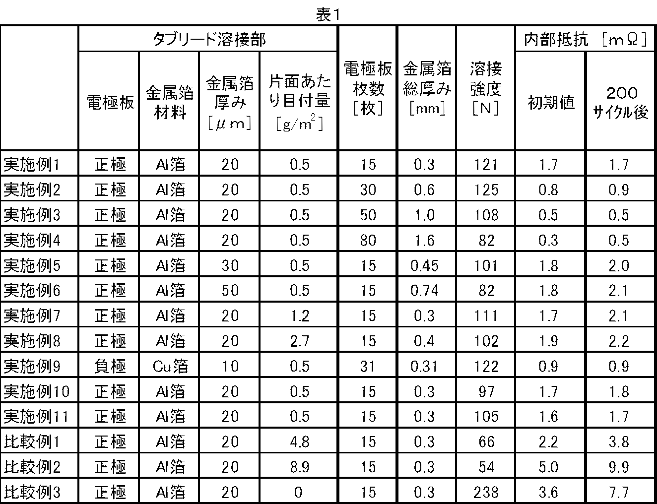
<電気二重層キャパシタの製造>
活性炭(クラレケミカル(株)製、商品名YP-50F)100質量部、アセチレンブラック(電気化学工業(株)製、商品名デンカブラック(粉状品))5質量部、スチレンブタジエンゴム(日本エイアンドエル(株)製、商品名ナルスターSR-103)7.5質量部、カルボキシメチルセルロース(ダイセルファインケム(株)製、商品名CMC DN-10L)2質量部、および純水200質量部を混合してペーストを得た。Al集電体の一辺から幅10mm×長さ100mmの縁部を除いて、Al集電体の両面にドクターブレード法にて前記ペーストを塗布した。その後、乾燥させ、プレスして、幅90mm×長さ100mm×厚さ80μmの電極層(活物質層)をAl集電体の両面にそれぞれ形成させた。これを電気二重層キャパシタ用の電極板とした。アンダーコート層が露出し、電極層を形成させなかった、幅10mm×長さ100mmの縁部をタブリード溶接部とした。 Example 12
<Manufacture of electric double layer capacitors>
100 parts by mass of activated carbon (Kuraray Chemical Co., Ltd., trade name YP-50F), 5 parts by mass of acetylene black (manufactured by Denki Kagaku Kogyo Co., Ltd., trade name Denka Black (powder)), styrene butadiene rubber (Nippon A & L) A paste prepared by mixing 7.5 parts by mass of trade name Nalstar SR-103 manufactured by Co., Ltd., 2 parts by mass of carboxymethylcellulose (manufactured by Daicel Finechem Co., Ltd., trade name CMC DN-10L), and 200 parts by mass of pure water Got. The paste was applied to both surfaces of the Al current collector by the doctor blade method except for an edge having a width of 10 mm and a length of 100 mm from one side of the Al current collector. Thereafter, drying and pressing were performed to form electrode layers (active material layers) each having a width of 90 mm, a length of 100 mm, and a thickness of 80 μm on both sides of the Al current collector. This was used as an electrode plate for an electric double layer capacitor. An edge portion having a width of 10 mm and a length of 100 mm, in which the undercoat layer was exposed and the electrode layer was not formed, was defined as a tab lead welded portion.
別の一枚のアルミニウム製タブリード(負極タブリード)と、電極板積層体の負極電極板のタブリード溶接部16枚とを、超音波溶接機で接合した。溶接は、ホーンの先端角度90度、圧力0.3MPa、周波数20kHzおよび0.3秒間の条件で行った。ホーンの先端は2mm×12mmの長方形で、溶接面積は24mm2であった。 Next, two aluminum tab leads (A1N30-H, thickness 0.5 mm, width 20 mm, length 30 mm) were prepared. One aluminum tab lead (positive electrode tab lead) and 15 tab lead welded portions of the positive electrode plate of the electrode plate laminate were joined by an ultrasonic welding machine. Welding was performed under the conditions of a horn tip angle of 90 degrees, a pressure of 0.3 MPa, a frequency of 20 kHz, and 0.3 seconds. The tip of the horn was a 2 mm × 12 mm rectangle, and the welding area was 24 mm 2 .
Another aluminum tab lead (negative electrode tab lead) and 16 tab lead welds of the negative electrode plate of the electrode plate laminate were joined with an ultrasonic welder. Welding was performed under the conditions of a horn tip angle of 90 degrees, a pressure of 0.3 MPa, a frequency of 20 kHz, and 0.3 seconds. The tip of the horn was a 2 mm × 12 mm rectangle, and the welding area was 24 mm 2 .
(溶接強度の測定)
測定は卓上型材料試験機((株)オリエンテック製、STA-1150)にて引張試験モードにて行った。評価試験用電気二重層キャパシタの正極タブリードとキャパシタ本体部とを各々チャックに挟んで固定し、5mm/minの速度で反対方向に引っ張り、破断するまでの最大荷重を測定し、それを溶接強度とした。なお、チャック間距離は50mmとし、タブリード溶接部がチャック間の中央に配置されるようにセットした。数値が大きいほど溶接強度が高いことを示す。結果を表2に示す。 <Evaluation of electric double layer capacitor>
(Measurement of welding strength)
The measurement was performed in a tensile test mode with a desktop material testing machine (STA-1150, manufactured by Orientec Co., Ltd.). The positive tab lead of the electric double layer capacitor for evaluation test and the capacitor body are sandwiched between the chucks, fixed at a speed of 5 mm / min, pulled in the opposite direction, and measured for the maximum load until breakage. did. The distance between chucks was set to 50 mm, and the tab lead weld was set so as to be arranged at the center between the chucks. It shows that welding strength is so high that a numerical value is large. The results are shown in Table 2.
評価試験用電気二重層キャパシタの内部抵抗は、インピーダンスメーター(日置電機(株)製、型式3532-80)を用いてACインピーダンス法で測定周波数1kHzにて測定した。なお、SOC(充電状態)100%の状態の値をもって内部抵抗とした。キャパシタ製造後の内部抵抗値を「初期値」として、結果を表2に示す。 (Measurement of internal resistance)
The internal resistance of the electric double layer capacitor for evaluation test was measured by an AC impedance method at a measurement frequency of 1 kHz using an impedance meter (manufactured by Hioki Electric Co., Ltd., model 3532-80). In addition, the value of the state of SOC (charged state) 100% was used as the internal resistance. The results are shown in Table 2 with the internal resistance value after manufacturing the capacitor as the “initial value”.
充放電装置(東洋システム株式会社製)を用いて、評価試験用電気二重層キャパシタに、電流密度1.59mA/cm2にて、0~2.5Vで充放電を500サイクル行った。その後、内部抵抗を測定した。500サイクル充放電後の内部抵抗値を「500サイクル後」として、結果を表2に示す。 (Cycle test)
Using a charge / discharge device (manufactured by Toyo System Co., Ltd.), 500 cycles of charge / discharge were performed on the electric double layer capacitor for evaluation test at 0 to 2.5 V at a current density of 1.59 mA / cm 2 . Thereafter, the internal resistance was measured. The internal resistance value after 500 cycles of charge / discharge is defined as “after 500 cycles”, and the results are shown in Table 2.
アンダーコート層用塗工液の固形分濃度を調整して片面あたりの目付量を1.2g/m2に変えた他は、実施例12と同じ手法にて電気二重層キャパシタを製造し、評価を行った。結果を表2に示す。 Example 13
An electric double layer capacitor was manufactured and evaluated in the same manner as in Example 12, except that the solid content concentration of the coating liquid for the undercoat layer was adjusted to change the basis weight per side to 1.2 g / m 2. Went. The results are shown in Table 2.
アンダーコート層用塗工液の固形分濃度を調整して片面あたりの目付量を2.7g/m2に変えた他は、実施例12と同じ手法にて電気二重層キャパシタを製造し、評価を行った。結果を表2に示す。 Example 14
An electric double layer capacitor was manufactured and evaluated in the same manner as in Example 12 except that the solid content concentration of the coating liquid for undercoat layer was adjusted to change the basis weight per side to 2.7 g / m 2. Went. The results are shown in Table 2.
アンダーコート層用塗工液の固形分濃度を調整して片面あたりの目付量を4.8g/m2に変えた他は、実施例12と同じ手法にて電気二重層キャパシタを製造し、評価を行った。結果を表2に示す。 Comparative Example 4
An electric double layer capacitor was manufactured and evaluated in the same manner as in Example 12 except that the solid content concentration of the coating liquid for the undercoat layer was adjusted to change the basis weight per side to 4.8 g / m 2. Went. The results are shown in Table 2.
アンダーコート層用塗工液の固形分濃度を調整して片面あたりの目付量を8.9g/m2に変えた他は、実施例12と同じ手法にて電気二重層キャパシタを製造し、評価を行った。結果を表2に示す。 Comparative Example 5
An electric double layer capacitor was manufactured and evaluated in the same manner as in Example 12 except that the solid content concentration of the coating liquid for undercoat layer was adjusted to change the basis weight per side to 8.9 g / m 2. Went. The results are shown in Table 2.

2、2’ : 金属箔
3、3’ : アンダーコート層
4、4’、4” : 活物質層
5n、5n’、5n” : 負極タブリード
3n、3n’、3n” : 負極のタブリード溶接部
5p、5p’、5p” : 正極タブリード
3p、3p’、3p” : 正極のタブリード溶接部
S、S’ : セパレータ
N、N’、N” : 負極
P、P’、P” : 正極 1, 1 ':
Claims (14)
- 一枚の金属タブリードと複数枚の電極板とからなる電極を少なくとも一つ有する蓄電デバイスであって、
電極板が、金属箔と、金属箔の片面または両面に形成されたアンダーコート層と、アンダーコート層が形成されている部分の一部表面に形成された活物質層とを有し、
アンダーコート層は炭素材料を含み且つ片面あたりの目付量が0.05~3g/m2であり、
複数枚の電極板はアンダーコート層が形成されている部分で且つ活物質層が形成されていない部分にて互いに溶接され、且つ
複数枚の電極板のうちの少なくとも1枚はアンダーコート層が形成されている部分で且つ活物質層が形成されていない部分にて金属タブリードと溶接されている、
蓄電デバイス。 An electricity storage device having at least one electrode composed of one metal tab lead and a plurality of electrode plates,
The electrode plate has a metal foil, an undercoat layer formed on one or both sides of the metal foil, and an active material layer formed on a part of the surface where the undercoat layer is formed,
The undercoat layer contains a carbon material and the basis weight per side is 0.05 to 3 g / m 2 .
The plurality of electrode plates are welded to each other at the portion where the undercoat layer is formed and the portion where the active material layer is not formed, and at least one of the plurality of electrode plates forms an undercoat layer Is welded to the metal tab lead at the portion where the active material layer is not formed.
Power storage device. - 複数枚の電極板の金属箔の厚さの合計が0.2~2mmである、請求項1に記載の蓄電デバイス。 2. The electricity storage device according to claim 1, wherein the total thickness of the metal foils of the plurality of electrode plates is 0.2 to 2 mm.
- アンダーコート層は、炭素材料1~60質量%を含む、請求項1または2に記載の蓄電デバイス。 3. The electricity storage device according to claim 1, wherein the undercoat layer contains 1 to 60% by mass of a carbon material.
- アンダーコート層は、炭素材料100質量部に対し、20~300質量部の結着材を含む、請求項1~3のいずれかひとつに記載の蓄電デバイス。 The electricity storage device according to any one of claims 1 to 3, wherein the undercoat layer includes 20 to 300 parts by mass of a binder with respect to 100 parts by mass of the carbon material.
- 結着材が、キトサンまたはその誘導体である請求項4に記載の蓄電デバイス。 The electricity storage device according to claim 4, wherein the binder is chitosan or a derivative thereof.
- 活物質層の面積が、アンダーコート層が形成されている部分の面積の80~99面積%である、請求項1~5のいずれか1項に記載の蓄電デバイス。 The electricity storage device according to any one of claims 1 to 5, wherein the area of the active material layer is 80 to 99% by area of the area where the undercoat layer is formed.
- 金属タブリードが、アルミニウム、銅およびニッケルからなる群より選ばれる少なくとも一つを含むものである、請求項1~6のいずれかひとつに記載の蓄電デバイス。 The electricity storage device according to any one of claims 1 to 6, wherein the metal tab lead includes at least one selected from the group consisting of aluminum, copper and nickel.
- 金属箔が、アルミニウム箔または銅箔である、請求項1~7のいずれかひとつに記載の蓄電デバイス。 The electricity storage device according to any one of claims 1 to 7, wherein the metal foil is an aluminum foil or a copper foil.
- 金属箔の1枚の厚さが5~70μmである、請求項1~8のいずれかひとつに記載の蓄電デバイス。 The electricity storage device according to any one of claims 1 to 8, wherein the thickness of one metal foil is 5 to 70 µm.
- 炭素材料は、黒鉛、導電性カーボンブラック、カーボンナノチューブおよびカーボンナノファイバーからなる群より選ばれる少なくとも一つを含むものである、請求項1~9のいずれかひとつに記載の蓄電デバイス。 The electricity storage device according to any one of claims 1 to 9, wherein the carbon material includes at least one selected from the group consisting of graphite, conductive carbon black, carbon nanotube, and carbon nanofiber.
- リチウムイオン電池である、請求項1~10のいずれかひとつに記載の蓄電デバイス。 The electricity storage device according to any one of claims 1 to 10, which is a lithium ion battery.
- 金属箔と、金属箔の片面または両面に形成されたアンダーコート層と、アンダーコート層が形成されている部分の一部表面に形成された活物質層とを有する電極板を複数枚用意する工程、および
複数枚の電極板をアンダーコート層が形成されている部分で且つ活物質層が形成されていない部分にて互いに溶接し、且つ複数枚の電極板のうちの少なくとも1枚をアンダーコート層が形成されている部分で且つ活物質層が形成されていない部分にて金属タブリードと溶接する工程
を含む請求項1~11のいずれかひとつに記載の蓄電デバイスの製造方法。 A step of preparing a plurality of electrode plates having a metal foil, an undercoat layer formed on one or both sides of the metal foil, and an active material layer formed on a part of the surface where the undercoat layer is formed And welding a plurality of electrode plates to each other at a portion where an undercoat layer is formed and a portion where an active material layer is not formed, and at least one of the plurality of electrode plates is an undercoat layer The method for manufacturing an electricity storage device according to any one of claims 1 to 11, further comprising a step of welding with a metal tab lead at a portion where the active material layer is not formed. - 溶接する工程がワンショット溶接で行われる、請求項12に記載の製造方法。 The manufacturing method according to claim 12, wherein the welding step is performed by one-shot welding.
- 溶接する工程が超音波溶接で行われる、請求項12または13に記載の製造方法。 The manufacturing method according to claim 12 or 13, wherein the welding step is performed by ultrasonic welding.
Priority Applications (6)
| Application Number | Priority Date | Filing Date | Title |
|---|---|---|---|
| ES13831991.8T ES2663236T3 (en) | 2012-08-29 | 2013-08-29 | Electricity storage device and procedure to produce the same |
| EP13831991.8A EP2892103B1 (en) | 2012-08-29 | 2013-08-29 | Electricity storage device and method for producing same |
| CN201380003647.3A CN103891029B (en) | 2012-08-29 | 2013-08-29 | Electrical storage device and manufacture method thereof |
| US14/424,605 US9478366B2 (en) | 2012-08-29 | 2013-08-29 | Electric storage device and method for producing the same |
| KR1020147007386A KR101452878B1 (en) | 2012-08-29 | 2013-08-29 | Electricity storage device and producing method thereof |
| JP2013552789A JP5468714B1 (en) | 2012-08-29 | 2013-08-29 | Electric storage device and manufacturing method thereof |
Applications Claiming Priority (2)
| Application Number | Priority Date | Filing Date | Title |
|---|---|---|---|
| JP2012-188605 | 2012-08-29 | ||
| JP2012188605 | 2012-08-29 |
Publications (1)
| Publication Number | Publication Date |
|---|---|
| WO2014034113A1 true WO2014034113A1 (en) | 2014-03-06 |
Family
ID=50182947
Family Applications (1)
| Application Number | Title | Priority Date | Filing Date |
|---|---|---|---|
| PCT/JP2013/005096 WO2014034113A1 (en) | 2012-08-29 | 2013-08-29 | Electricity storage device and method for producing same |
Country Status (8)
| Country | Link |
|---|---|
| US (1) | US9478366B2 (en) |
| EP (1) | EP2892103B1 (en) |
| JP (3) | JP5468714B1 (en) |
| KR (1) | KR101452878B1 (en) |
| CN (1) | CN103891029B (en) |
| ES (1) | ES2663236T3 (en) |
| TW (1) | TWI569498B (en) |
| WO (1) | WO2014034113A1 (en) |
Cited By (17)
| Publication number | Priority date | Publication date | Assignee | Title |
|---|---|---|---|---|
| JP2014075335A (en) * | 2012-09-13 | 2014-04-24 | Gs Yuasa Corp | Electrode body, method of manufacturing electrode body and storage element having electrode body |
| CN104241708A (en) * | 2014-09-11 | 2014-12-24 | 长兴超越动力科技有限公司 | Lead-acid storage battery with high energy storage capacity and long service life |
| JP2015191905A (en) * | 2014-03-27 | 2015-11-02 | 株式会社大木工藝 | electric double layer capacitor |
| JP2016066454A (en) * | 2014-09-24 | 2016-04-28 | 株式会社Gsユアサ | Power storage element |
| WO2016194747A1 (en) * | 2015-06-04 | 2016-12-08 | 日産化学工業株式会社 | Undercoat foil for energy storage device electrode |
| JP2017120766A (en) * | 2015-12-25 | 2017-07-06 | パナソニック株式会社 | Positive electrode for nonaqueous electrolyte secondary battery, and nonaqueous electrolyte secondary battery |
| WO2018101305A1 (en) | 2016-12-02 | 2018-06-07 | 日産化学工業株式会社 | Undercoat layer for energy storage device, and undercoat foil for energy storage device electrode |
| WO2018101301A1 (en) * | 2016-12-02 | 2018-06-07 | 日産化学工業株式会社 | Carbon nanotube-containing thin film |
| WO2018101307A1 (en) * | 2016-12-02 | 2018-06-07 | 日産化学工業株式会社 | Thin film, and undercoat foil for energy storage device electrode |
| JPWO2017038044A1 (en) * | 2015-08-31 | 2018-06-14 | パナソニックIpマネジメント株式会社 | battery |
| JP2018160440A (en) * | 2017-03-24 | 2018-10-11 | 三洋電機株式会社 | Method for manufacturing electrode plate, and method for manufacturing secondary battery |
| JPWO2017163726A1 (en) * | 2016-03-22 | 2019-01-31 | パナソニックIpマネジメント株式会社 | Positive electrode for electrochemical device with lead member, method for producing the same, and electrochemical device |
| JP2020107496A (en) * | 2018-12-27 | 2020-07-09 | 三洋電機株式会社 | Secondary battery |
| CN113097656A (en) * | 2021-05-10 | 2021-07-09 | 厦门海辰新能源科技有限公司 | Pole piece, electric core subassembly and battery |
| WO2022050046A1 (en) * | 2020-09-02 | 2022-03-10 | 株式会社村田製作所 | Secondary battery |
| US11469422B2 (en) | 2017-11-29 | 2022-10-11 | Gs Yuasa International Ltd. | Plate, electrode assembly, and energy storage device |
| WO2023090248A1 (en) * | 2021-11-19 | 2023-05-25 | 日本電気硝子株式会社 | Method for producing member for power storage devices |
Families Citing this family (33)
| Publication number | Priority date | Publication date | Assignee | Title |
|---|---|---|---|---|
| WO2014049697A1 (en) * | 2012-09-26 | 2014-04-03 | 昭和電工株式会社 | Negative electrode for secondary batteries, and secondary battery |
| KR20160001783A (en) * | 2014-06-26 | 2016-01-07 | 에스케이이노베이션 주식회사 | Secondary battery with improved high-temperature and low-temperature properties |
| US10312028B2 (en) | 2014-06-30 | 2019-06-04 | Avx Corporation | Electrochemical energy storage devices and manufacturing methods |
| CN104347879B (en) * | 2014-09-11 | 2016-08-24 | 浙江超越动力科技股份有限公司 | A kind of lead-acid accumulator premix composite negative pole additive |
| TWI678831B (en) * | 2014-12-31 | 2019-12-01 | 王琮淇 | Battery pack |
| US10741819B2 (en) * | 2015-03-23 | 2020-08-11 | Kabushiki Kaisha Toyota Jidoshokki | Electricity storage device and method for manufacturing electricity storage device |
| JP6589239B2 (en) | 2015-09-25 | 2019-10-16 | 株式会社Screenホールディングス | Film thickness measuring apparatus and film thickness measuring method |
| US9979009B2 (en) * | 2015-12-17 | 2018-05-22 | Intel Corporation | Energy storage device having a laser weld |
| KR20180100205A (en) * | 2016-01-07 | 2018-09-07 | 닛산 가가쿠 가부시키가이샤 | Electrodes for energy storage devices |
| KR20180101461A (en) | 2016-01-07 | 2018-09-12 | 닛산 가가쿠 가부시키가이샤 | Electrodes for energy storage devices |
| DE112017002192T5 (en) | 2016-04-26 | 2019-01-03 | Gs Yuasa International Ltd. | Energy storage device and method for its production |
| WO2017201167A1 (en) * | 2016-05-20 | 2017-11-23 | Avx Corporation | Electrode configuration for an ultracapacitor |
| EP3459094B1 (en) | 2016-05-20 | 2022-08-17 | KYOCERA AVX Components Corporation | Ultracapacitor for use at high temperatures |
| MY195773A (en) | 2016-05-20 | 2023-02-11 | Kyocera Avx Components Corp | Multi-Cell Ultracapacitor |
| KR102386805B1 (en) * | 2016-05-20 | 2022-04-14 | 교세라 에이브이엑스 컴포넌츠 코포레이션 | Non-aqueous electrolyte for ultracapacitors |
| EP3267514B1 (en) * | 2016-07-06 | 2021-01-27 | LiCAP Technologies, Inc. | Lithium attached electrodes and method of making same |
| CN110022991A (en) * | 2016-12-02 | 2019-07-16 | 日产化学株式会社 | The manufacturing method of film containing conductive carbon material |
| CN110062972B (en) * | 2016-12-02 | 2022-07-01 | 日产化学株式会社 | Film and undercoat foil for energy storage device electrode |
| US20190300369A1 (en) * | 2016-12-02 | 2019-10-03 | Nissan Chemical Corporation | Production method for thin film containing conductive carbon material |
| JP7033700B2 (en) * | 2016-12-28 | 2022-03-11 | パナソニックIpマネジメント株式会社 | Electrochemical device |
| KR102155029B1 (en) * | 2017-06-27 | 2020-09-11 | 주식회사 엘지화학 | Welding method of electrode tap and cable-type secondary battery comprising electrode welded by the same |
| JP6834870B2 (en) * | 2017-09-15 | 2021-02-24 | トヨタ自動車株式会社 | Non-aqueous electrolyte secondary battery and its manufacturing method |
| MX2020003817A (en) * | 2017-10-03 | 2020-11-09 | Fastcap Systems Corp | Chip form ultracapacitor. |
| KR102421801B1 (en) * | 2017-11-28 | 2022-07-15 | 주식회사 엘지에너지솔루션 | Welding method of electrode tap and lead |
| WO2019188559A1 (en) * | 2018-03-29 | 2019-10-03 | 日産化学株式会社 | Undercoat foil for energy storage device electrode |
| JP7438605B2 (en) * | 2018-04-11 | 2024-02-27 | エルジー エナジー ソリューション リミテッド | Method for manufacturing battery components for secondary batteries |
| WO2019198723A1 (en) * | 2018-04-11 | 2019-10-17 | 日立化成株式会社 | Method for producing battery member for secondary batteries |
| CN111244388B (en) * | 2018-07-13 | 2022-02-25 | 宁德时代新能源科技股份有限公司 | Pole piece, manufacturing method of pole piece and secondary battery |
| FR3084529B1 (en) * | 2018-07-24 | 2022-03-25 | Armor | METHOD FOR MANUFACTURING A CURRENT COLLECTOR AND ASSOCIATED DEVICES |
| JP2021051944A (en) * | 2019-09-25 | 2021-04-01 | 積水化学工業株式会社 | Power storage element and manufacturing method thereof |
| RU2726945C1 (en) * | 2019-12-16 | 2020-07-17 | Общество с ограниченной ответственнотью "ИОН" | Flat supercapacitor based on carbon-carbon nanocomposite and method of its production |
| WO2022077371A1 (en) * | 2020-10-15 | 2022-04-21 | 宁德时代新能源科技股份有限公司 | Secondary battery, manufacturing method for same, and related thereto, battery module, battery pack, and device |
| CN115148955A (en) * | 2021-03-29 | 2022-10-04 | 北京小米移动软件有限公司 | Negative pole piece and manufacturing method thereof, battery cell, battery and electronic equipment |
Citations (11)
| Publication number | Priority date | Publication date | Assignee | Title |
|---|---|---|---|---|
| JP2001351612A (en) | 2000-06-06 | 2001-12-21 | Matsushita Battery Industrial Co Ltd | Non-aqueous electrolyte secondary battery |
| JP2003157852A (en) * | 2001-11-19 | 2003-05-30 | Denso Corp | Method of manufacturing positive electrode for lithium battery and positive electrode |
| JP2006004739A (en) * | 2004-06-17 | 2006-01-05 | Toyota Motor Corp | Lithium secondary battery and positive electrode equipped with the battery, and its manufacturing method |
| JP2007226969A (en) * | 2005-02-10 | 2007-09-06 | Showa Denko Kk | Current collector for secondary battery, positive electrode for the secondary battery, negative electrode for the secondary battery, the secondary battery, and manufacturing method of them |
| JP2008098590A (en) | 2006-10-16 | 2008-04-24 | Nippon Zeon Co Ltd | Electrode for electrochemical device and electrochemical device using the same |
| JP2009076301A (en) * | 2007-09-20 | 2009-04-09 | Nec Tokin Corp | Nonaqueous electrolyte secondary battery |
| JP2009252396A (en) * | 2008-04-02 | 2009-10-29 | Toyota Motor Corp | Lithium secondary battery cathode and method for manufacturing the same |
| JP2010170965A (en) | 2009-01-26 | 2010-08-05 | Toyota Motor Corp | Positive electrode for lithium secondary battery, and its manufacturing method |
| US20120078629A1 (en) | 2010-09-28 | 2012-03-29 | Kabushiki Kaisha Toshiba | Meeting support apparatus, method and program |
| JP2012074369A (en) * | 2010-09-02 | 2012-04-12 | Showa Denko Kk | Collector and method for producing collector |
| JP2013110098A (en) * | 2011-10-25 | 2013-06-06 | Kobe Steel Ltd | Collector, method for manufacturing collector, electrode and secondary battery |
Family Cites Families (16)
| Publication number | Priority date | Publication date | Assignee | Title |
|---|---|---|---|---|
| EP0662728B1 (en) * | 1993-12-29 | 1998-04-29 | TDK Corporation | Lithium secondary cell |
| CN1169250C (en) * | 1995-03-06 | 2004-09-29 | 宇部兴产株式会社 | Nonaqueous secondary cell |
| JP4262795B2 (en) * | 1998-02-18 | 2009-05-13 | パナソニック株式会社 | Battery electrode connection method |
| US6387561B1 (en) * | 1998-10-13 | 2002-05-14 | Ngk Insulators, Ltd. | Electrolyte-solution filling method and battery structure of lithium secondary battery |
| JP2005050669A (en) * | 2003-07-28 | 2005-02-24 | Tdk Corp | Electrode and electrochemical element using it |
| WO2006085691A1 (en) | 2005-02-10 | 2006-08-17 | Showa Denko K.K | Secondary-battery cutrrent collector, secondary-battery cathode, secondary-battery anode, secondary battery and production method thereof |
| EP2012331A4 (en) * | 2006-04-25 | 2012-05-09 | Showa Denko Kk | Electric double-layered capacitor |
| JP2010062063A (en) * | 2008-09-05 | 2010-03-18 | Toyota Motor Corp | Current collecting foil for battery, method of manufacturing the same, and battery |
| JP2011216402A (en) * | 2010-04-01 | 2011-10-27 | Hitachi Vehicle Energy Ltd | Square secondary battery |
| EP2592674B1 (en) * | 2010-07-06 | 2015-09-30 | GS Yuasa International Ltd. | Electrode assembly for electric storage device and electric storage device |
| US20130196230A1 (en) | 2010-09-02 | 2013-08-01 | Showa Denko K.K. | Coating solution, electric collector, and method for producing electric collector |
| KR101513821B1 (en) * | 2010-10-21 | 2015-04-20 | 도요타지도샤가부시키가이샤 | Battery electrode and use thereof |
| WO2012057335A1 (en) * | 2010-10-29 | 2012-05-03 | 三洋電機株式会社 | Rectangular secondary battery |
| CN103229344B (en) * | 2010-12-08 | 2016-03-02 | 丰田自动车株式会社 | Lithium rechargeable battery |
| JPWO2012096189A1 (en) | 2011-01-14 | 2014-06-09 | 昭和電工株式会社 | Current collector |
| WO2012108212A1 (en) * | 2011-02-10 | 2012-08-16 | 昭和電工株式会社 | Current collector |
-
2013
- 2013-08-29 US US14/424,605 patent/US9478366B2/en active Active
- 2013-08-29 WO PCT/JP2013/005096 patent/WO2014034113A1/en active Application Filing
- 2013-08-29 EP EP13831991.8A patent/EP2892103B1/en not_active Not-in-force
- 2013-08-29 CN CN201380003647.3A patent/CN103891029B/en not_active Expired - Fee Related
- 2013-08-29 TW TW102131037A patent/TWI569498B/en not_active IP Right Cessation
- 2013-08-29 KR KR1020147007386A patent/KR101452878B1/en active IP Right Grant
- 2013-08-29 JP JP2013552789A patent/JP5468714B1/en active Active
- 2013-08-29 ES ES13831991.8T patent/ES2663236T3/en active Active
-
2014
- 2014-01-29 JP JP2014013955A patent/JP2014116317A/en active Pending
-
2018
- 2018-04-18 JP JP2018079808A patent/JP2018137236A/en active Pending
Patent Citations (13)
| Publication number | Priority date | Publication date | Assignee | Title |
|---|---|---|---|---|
| JP2001351612A (en) | 2000-06-06 | 2001-12-21 | Matsushita Battery Industrial Co Ltd | Non-aqueous electrolyte secondary battery |
| JP2003157852A (en) * | 2001-11-19 | 2003-05-30 | Denso Corp | Method of manufacturing positive electrode for lithium battery and positive electrode |
| JP2006004739A (en) * | 2004-06-17 | 2006-01-05 | Toyota Motor Corp | Lithium secondary battery and positive electrode equipped with the battery, and its manufacturing method |
| JP2007226969A (en) * | 2005-02-10 | 2007-09-06 | Showa Denko Kk | Current collector for secondary battery, positive electrode for the secondary battery, negative electrode for the secondary battery, the secondary battery, and manufacturing method of them |
| JP2008098590A (en) | 2006-10-16 | 2008-04-24 | Nippon Zeon Co Ltd | Electrode for electrochemical device and electrochemical device using the same |
| JP2009076301A (en) * | 2007-09-20 | 2009-04-09 | Nec Tokin Corp | Nonaqueous electrolyte secondary battery |
| JP2009252396A (en) * | 2008-04-02 | 2009-10-29 | Toyota Motor Corp | Lithium secondary battery cathode and method for manufacturing the same |
| JP2010170965A (en) | 2009-01-26 | 2010-08-05 | Toyota Motor Corp | Positive electrode for lithium secondary battery, and its manufacturing method |
| US20110274971A1 (en) | 2009-01-26 | 2011-11-10 | Hiroyuki Sakamoto | Positive electrode for lithium secondary battery and production method of same |
| JP2012074369A (en) * | 2010-09-02 | 2012-04-12 | Showa Denko Kk | Collector and method for producing collector |
| US20120078629A1 (en) | 2010-09-28 | 2012-03-29 | Kabushiki Kaisha Toshiba | Meeting support apparatus, method and program |
| JP2012073396A (en) | 2010-09-28 | 2012-04-12 | Toshiba Corp | Conference support device, method and program |
| JP2013110098A (en) * | 2011-10-25 | 2013-06-06 | Kobe Steel Ltd | Collector, method for manufacturing collector, electrode and secondary battery |
Non-Patent Citations (1)
| Title |
|---|
| See also references of EP2892103A4 |
Cited By (36)
| Publication number | Priority date | Publication date | Assignee | Title |
|---|---|---|---|---|
| US9865881B2 (en) | 2012-09-13 | 2018-01-09 | Gs Yuasa International Ltd. | Electrode assembly, method for producing electrode assembly, and electric storage device including electrode assembly |
| JP2014075335A (en) * | 2012-09-13 | 2014-04-24 | Gs Yuasa Corp | Electrode body, method of manufacturing electrode body and storage element having electrode body |
| JP2015191905A (en) * | 2014-03-27 | 2015-11-02 | 株式会社大木工藝 | electric double layer capacitor |
| CN104241708A (en) * | 2014-09-11 | 2014-12-24 | 长兴超越动力科技有限公司 | Lead-acid storage battery with high energy storage capacity and long service life |
| CN104241708B (en) * | 2014-09-11 | 2016-04-20 | 浙江超越动力科技股份有限公司 | A kind of high energy storage long service life head-acid accumulator |
| JP2016066454A (en) * | 2014-09-24 | 2016-04-28 | 株式会社Gsユアサ | Power storage element |
| US11251435B2 (en) | 2015-06-04 | 2022-02-15 | Nissan Chemical Industries, Ltd. | Undercoat foil for energy storage device electrode |
| EP3306716A4 (en) * | 2015-06-04 | 2019-01-23 | Nissan Chemical Corporation | Undercoat foil for energy storage device electrode |
| JP2018049847A (en) * | 2015-06-04 | 2018-03-29 | 日産化学工業株式会社 | Undercoat foil for energy storage device electrode |
| JP7035496B2 (en) | 2015-06-04 | 2022-03-15 | 日産化学株式会社 | Undercoat foil for energy storage device electrodes |
| WO2016194747A1 (en) * | 2015-06-04 | 2016-12-08 | 日産化学工業株式会社 | Undercoat foil for energy storage device electrode |
| KR20180101638A (en) | 2015-06-04 | 2018-09-12 | 닛산 가가쿠 가부시키가이샤 | Undercoat foil for energy storage device electrode |
| JPWO2016194747A1 (en) * | 2015-06-04 | 2017-09-28 | 日産化学工業株式会社 | Undercoat foil for energy storage device electrode |
| JPWO2017038044A1 (en) * | 2015-08-31 | 2018-06-14 | パナソニックIpマネジメント株式会社 | battery |
| JP2017120766A (en) * | 2015-12-25 | 2017-07-06 | パナソニック株式会社 | Positive electrode for nonaqueous electrolyte secondary battery, and nonaqueous electrolyte secondary battery |
| US11063324B2 (en) | 2016-03-22 | 2021-07-13 | Panasonic Intellectual Property Management Co., Ltd. | Positive electrode with lead member for electrochemical devices, method for producing same and electrochemical device |
| JPWO2017163726A1 (en) * | 2016-03-22 | 2019-01-31 | パナソニックIpマネジメント株式会社 | Positive electrode for electrochemical device with lead member, method for producing the same, and electrochemical device |
| JP2019140119A (en) * | 2016-12-02 | 2019-08-22 | 日産化学株式会社 | Undercoat foil for energy storage device electrode |
| WO2018101307A1 (en) * | 2016-12-02 | 2018-06-07 | 日産化学工業株式会社 | Thin film, and undercoat foil for energy storage device electrode |
| CN110024192A (en) * | 2016-12-02 | 2019-07-16 | 日产化学株式会社 | Energy storage device priming coat and energy storage device electrode primary coat foil |
| KR20190087536A (en) | 2016-12-02 | 2019-07-24 | 닛산 가가쿠 가부시키가이샤 | Undercoat layer for energy storage device and undercoat foil for energy storage device electrode |
| KR20230162126A (en) | 2016-12-02 | 2023-11-28 | 닛산 가가쿠 가부시키가이샤 | Undercoat layer for energy storage device, and undercoat foil for energy storage device electrode |
| JP2019140110A (en) * | 2016-12-02 | 2019-08-22 | 日産化学株式会社 | Undercoat foil for energy storage device electrode |
| JPWO2018101301A1 (en) * | 2016-12-02 | 2019-10-24 | 日産化学株式会社 | Carbon nanotube-containing thin film |
| JP7047807B2 (en) | 2016-12-02 | 2022-04-05 | 日産化学株式会社 | Undercoat foil for energy storage device electrodes |
| WO2018101305A1 (en) | 2016-12-02 | 2018-06-07 | 日産化学工業株式会社 | Undercoat layer for energy storage device, and undercoat foil for energy storage device electrode |
| JPWO2018101307A1 (en) * | 2016-12-02 | 2018-11-29 | 日産化学株式会社 | Undercoat foil for energy storage device electrode |
| WO2018101301A1 (en) * | 2016-12-02 | 2018-06-07 | 日産化学工業株式会社 | Carbon nanotube-containing thin film |
| JP2018160440A (en) * | 2017-03-24 | 2018-10-11 | 三洋電機株式会社 | Method for manufacturing electrode plate, and method for manufacturing secondary battery |
| US11469422B2 (en) | 2017-11-29 | 2022-10-11 | Gs Yuasa International Ltd. | Plate, electrode assembly, and energy storage device |
| JP2020107496A (en) * | 2018-12-27 | 2020-07-09 | 三洋電機株式会社 | Secondary battery |
| JP7108533B2 (en) | 2018-12-27 | 2022-07-28 | 三洋電機株式会社 | secondary battery |
| WO2022050046A1 (en) * | 2020-09-02 | 2022-03-10 | 株式会社村田製作所 | Secondary battery |
| CN113097656A (en) * | 2021-05-10 | 2021-07-09 | 厦门海辰新能源科技有限公司 | Pole piece, electric core subassembly and battery |
| CN113097656B (en) * | 2021-05-10 | 2023-04-25 | 厦门海辰储能科技股份有限公司 | Pole piece, battery core assembly and battery |
| WO2023090248A1 (en) * | 2021-11-19 | 2023-05-25 | 日本電気硝子株式会社 | Method for producing member for power storage devices |
Also Published As
| Publication number | Publication date |
|---|---|
| TW201419634A (en) | 2014-05-16 |
| CN103891029A (en) | 2014-06-25 |
| EP2892103A4 (en) | 2016-07-20 |
| JP2018137236A (en) | 2018-08-30 |
| ES2663236T3 (en) | 2018-04-11 |
| JP5468714B1 (en) | 2014-04-09 |
| US9478366B2 (en) | 2016-10-25 |
| TWI569498B (en) | 2017-02-01 |
| US20150213967A1 (en) | 2015-07-30 |
| EP2892103B1 (en) | 2018-02-14 |
| CN103891029B (en) | 2015-12-30 |
| JP2014116317A (en) | 2014-06-26 |
| EP2892103A1 (en) | 2015-07-08 |
| KR101452878B1 (en) | 2014-10-22 |
| KR20140048336A (en) | 2014-04-23 |
| JPWO2014034113A1 (en) | 2016-08-08 |
Similar Documents
| Publication | Publication Date | Title |
|---|---|---|
| JP5468714B1 (en) | Electric storage device and manufacturing method thereof | |
| US9666858B2 (en) | Negative electrode for secondary battery, and process for production thereof | |
| JP5871302B2 (en) | Negative electrode for secondary battery and secondary battery | |
| JP5444781B2 (en) | Electrode for lithium ion secondary battery and lithium ion secondary battery | |
| US20150093649A1 (en) | Method of producing current collector for electrochemical element, method of producing electrode for electrochemical element, current collector for electrochemical element, electrochemical element, and coating liquid for fabricating current collector for electrochemical element | |
| KR101691757B1 (en) | Negative electrode for secondary batteries, and secondary battery | |
| JP2011222215A (en) | Lithium ion secondary battery | |
| CN115911246A (en) | Pole piece and secondary battery comprising same | |
| JP6436101B2 (en) | Electrode for electrochemical element and electrochemical element | |
| CN115820047A (en) | Electrode pole piece, preparation method thereof, battery and power utilization device | |
| JP2019175657A (en) | Lithium ion secondary battery | |
| JP2012256544A (en) | Manufacturing method of electrode for secondary battery | |
| JP2013161689A (en) | Secondary battery electrode and manufacturing method of the same | |
| JP2006278143A (en) | Battery with spiral electrode | |
| JP5725356B2 (en) | Method for manufacturing electrode for secondary battery | |
| JP6519314B2 (en) | Negative electrode for non-aqueous electrolyte secondary battery and method for manufacturing the same | |
| JP5704401B2 (en) | Secondary battery electrode and manufacturing method thereof | |
| EP3680960A1 (en) | Electrode and lithium ion secondary battery | |
| JP6846570B2 (en) | Manufacturing method of non-aqueous electrolyte secondary battery and non-aqueous electrolyte secondary battery | |
| WO2024079848A1 (en) | Lithium secondary battery and method for producing same | |
| JP2018160440A (en) | Method for manufacturing electrode plate, and method for manufacturing secondary battery | |
| WO2021010185A1 (en) | Positive electrode and lithium ion secondary battery | |
| JP2024027111A (en) | Cross-linked binder-containing electrodes for electrochemical energy storage devices |
Legal Events
| Date | Code | Title | Description |
|---|---|---|---|
| ENP | Entry into the national phase |
Ref document number: 2013552789 Country of ref document: JP Kind code of ref document: A |
|
| ENP | Entry into the national phase |
Ref document number: 20147007386 Country of ref document: KR Kind code of ref document: A |
|
| 121 | Ep: the epo has been informed by wipo that ep was designated in this application |
Ref document number: 13831991 Country of ref document: EP Kind code of ref document: A1 |
|
| WWE | Wipo information: entry into national phase |
Ref document number: 14424605 Country of ref document: US |
|
| NENP | Non-entry into the national phase |
Ref country code: DE |