WO2021010185A1 - Positive electrode and lithium ion secondary battery - Google Patents
Positive electrode and lithium ion secondary battery Download PDFInfo
- Publication number
- WO2021010185A1 WO2021010185A1 PCT/JP2020/026133 JP2020026133W WO2021010185A1 WO 2021010185 A1 WO2021010185 A1 WO 2021010185A1 JP 2020026133 W JP2020026133 W JP 2020026133W WO 2021010185 A1 WO2021010185 A1 WO 2021010185A1
- Authority
- WO
- WIPO (PCT)
- Prior art keywords
- positive electrode
- active material
- material layer
- negative electrode
- current collector
- Prior art date
Links
Images
Classifications
-
- H—ELECTRICITY
- H01—ELECTRIC ELEMENTS
- H01M—PROCESSES OR MEANS, e.g. BATTERIES, FOR THE DIRECT CONVERSION OF CHEMICAL ENERGY INTO ELECTRICAL ENERGY
- H01M4/00—Electrodes
- H01M4/02—Electrodes composed of, or comprising, active material
- H01M4/13—Electrodes for accumulators with non-aqueous electrolyte, e.g. for lithium-accumulators; Processes of manufacture thereof
-
- Y—GENERAL TAGGING OF NEW TECHNOLOGICAL DEVELOPMENTS; GENERAL TAGGING OF CROSS-SECTIONAL TECHNOLOGIES SPANNING OVER SEVERAL SECTIONS OF THE IPC; TECHNICAL SUBJECTS COVERED BY FORMER USPC CROSS-REFERENCE ART COLLECTIONS [XRACs] AND DIGESTS
- Y02—TECHNOLOGIES OR APPLICATIONS FOR MITIGATION OR ADAPTATION AGAINST CLIMATE CHANGE
- Y02E—REDUCTION OF GREENHOUSE GAS [GHG] EMISSIONS, RELATED TO ENERGY GENERATION, TRANSMISSION OR DISTRIBUTION
- Y02E60/00—Enabling technologies; Technologies with a potential or indirect contribution to GHG emissions mitigation
- Y02E60/10—Energy storage using batteries
Definitions
- the present invention relates to a positive electrode and a lithium ion secondary battery.
- the present application claims priority based on Japanese Patent Application No. 2019-130399 filed in Japan on July 12, 2019, the contents of which are incorporated herein by reference.
- Lithium-ion secondary batteries can achieve high capacity and are widely used from mobile batteries for mobile phones and laptop computers to automobile batteries and large-scale power storage batteries.
- the electrode of the lithium ion secondary battery has a coated portion in which the active material layer is coated on the current collector and an uncoated portion in which the active material layer is not coated, and a connecting portion (tab) for connecting an external terminal to the uncoated portion.
- a cell single tab cell that derives an external terminal from a single connection portion connected to an uncoated portion is a cell (multi-tab cell) that has a connection portion that connects external terminals to a plurality of uncoated portions. It is possible to charge and discharge at a higher current density.
- the present invention has been made in view of the above circumstances, and an object of the present invention is to provide a positive electrode for a lithium ion secondary battery and a lithium ion secondary battery capable of obtaining high cycle characteristics.
- the present inventors have found that the ratio of the sum Ts of the cross-sectional area of the distal end of the connecting portion to the total area Es of the active material layer (Es / Ts) is a 1.90 ⁇ 10 4 ⁇ 2.55 ⁇ 10 5
- Es / Ts the ratio of the sum Ts of the cross-sectional area of the distal end of the connecting portion to the total area Es of the active material layer
- a positive electrode including a current collector and an active material layer.
- the current collector includes a coated portion having an active material layer on at least one surface and a non-coated portion having no active material layer.
- the current collector has one or more connection portions connected to external terminals in the uncoated portion, and the connection portion has a tip in the external terminal lead-out direction.
- a positive electrode characterized in that the total area Es of the active material layer and the total Ts of the cross-sectional area of the tip of the connecting portion satisfy the relationship of the following formula (1).
- a lithium ion secondary battery comprising the positive electrode according to any one of [1] to [4], a negative electrode, a separator separating the positive electrode and the negative electrode, and an electrolyte.
- the present inventors have a ratio (Es / Ts) of the total area Es of the active material layer to the total Ts of the cross-sectional area of the tip of the connecting portion of 1.90 ⁇ 10 4 to. by to 2.55 ⁇ 10 5, increase the heat radiation at the time of discharge, it is possible to provide a lithium ion secondary battery having a positive electrode and its high cycle characteristics can be obtained.
- FIG. 1 It is sectional drawing of the lithium ion secondary battery which concerns on one Embodiment of this invention. It is a schematic diagram of the winding body of the lithium ion secondary battery which concerns on one Embodiment of this invention. It is a schematic diagram of the shape of the positive electrode of the lithium ion secondary battery which concerns on Example 1. FIG. It is a schematic diagram of the shape of the negative electrode of the lithium ion secondary battery which concerns on Example 1. FIG.
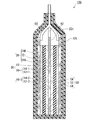
- FIG. 1 is a schematic cross-sectional view of the lithium ion secondary battery according to the present embodiment.
- the lithium ion secondary battery 100 shown in FIG. 1 mainly includes a laminate 30, a case 50 that houses the laminate 30 in a sealed state, and a pair of leads 60 and 62 connected to the laminate 30.
- the electrolytic solution is housed in the case 50 together with the laminated body 30.
- the laminated body 30 includes a positive electrode 20, a first negative electrode 10-1, a second negative electrode 10-2, and a separator 18 in the case 50.
- the first negative electrode 10-1 or the second negative electrode 10-2 is arranged so that the positive electrode 20 and the positive electrode 20 face each other with the separator 18 interposed therebetween.
- the number of layers of the positive electrode and the negative electrode may be further increased.
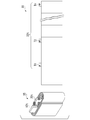
- the laminate 30 of the present invention is a laminate in which the positive electrodes, separators, negative electrodes, etc.
- laminate body A laminated body made of a wound body 35 as shown in FIG. 2 (also referred to as “laminated body B”).
- the positive electrode of the present embodiment includes a current collector and an active material layer.
- the current collector includes a coated portion having an active material layer on at least one surface, and a non-coated portion having no active material layer.
- the current collector has one or more connecting portions (sometimes referred to as “tabs") connected to external terminals in the uncoated portion.
- the connection portion has a tip in the direction of leading out the external terminal.
- the total area Es of the active material layer and the total cross-sectional area Ts of the tip of the connecting portion satisfy the relationship of the following formula (1).
- the ratio (Es / Ts) of the total area Es of the active material layer to the total Ts of the cross-sectional area of the tip of the connecting portion satisfies the relationship of the following formula (2).
- the cross-sectional area of the tip is the area of the cross section perpendicular to the current direction of the connection portion.
- the total area of the active material layer is defined as the total area of the coating portion having the active material layer on the current collector before winding. is there.
- the total area of the active material layer is Es, which is the total area of the coating portion having the active material layer on each positive electrode current collector layer.
- the ratio of the total area of the cross-sectional area of the distal end of the connecting portion to the total area of the active material layer (Es / Ts) is less than 1.90 ⁇ 10 4, after the winding too many number of tabs Since tab alignment may be difficult, there is a demerit that it is difficult to make things due to manufacturing problems. 2.55 ⁇ 10 5 If it exceeds, the desired properties number of tabs is too small, for example, the output characteristics may not be obtained, cycle deterioration by heat reservoir proceeds, a problem arises.
- a more preferable range of the ratio of the total area of the cross-sectional area of the distal end of the connecting portion to the total area of the active material layer (Es / Ts) is at 2.5 ⁇ 10 4 ⁇ 1.0 ⁇ 10 5 , A more preferable range is 3.8 ⁇ 10 4 to 9.4 ⁇ 10 4 .
- the total volume Ev in the active material layer is preferably from 3.4cm 3 ⁇ Ev ⁇ 300cm 3, more preferably 3.4cm 3 ⁇ Ev ⁇ 34.1cm 3. If the total volume Ev is less than 3.4 cm 3 , the electrode thickness or area is too small, and it is not suitable for manufacturing. If the total volume Ev exceeds 300 cm 3 , the electrode thickness is too thick and it is not suitable for manufacturing.
- a sum Ts of the cross-sectional area of the distal end of the connecting portion more preferably 0.003cm 2 ⁇ Ts ⁇ 0.68cm 2, further preferably 0.003cm 2 ⁇ Ts ⁇ 0.60cm 2 ..
- the preferable range of the total Ts of the cross-sectional area of the tip of the connecting portion is 0.003 to 0.60 cm 2 , the more preferable range is 0.005 to 0.30 cm 2 , and the more preferable range is 0.015. It is ⁇ 0.10 cm 2 .
- the thermal conductivity ⁇ of the positive electrode of the present embodiment in the thickness direction is 1.1 W / mK ⁇ ⁇ ⁇ 3.0 W / mK. If ⁇ is less than 1.1 W / mK, there arises a problem that sufficient heat conduction required for heat dissipation cannot be secured, desired characteristics such as output characteristics cannot be obtained, and cycle deterioration progresses due to heat accumulation. Further, when ⁇ exceeds 3.0 W / mK, there is a problem that the addition rate of the heat conductive material increases and the capacity decreases by that amount.
- the thermal conductivity ⁇ can be measured by a conventionally known “laser flash” method.
- a thermal constant measuring device TC-7000 manufactured by Vacuum Riko Co., Ltd. is used, and the thermal conductivity ⁇ can be calculated by the heat capacity and the electrode density according to the following equation (3).
- ⁇ ⁇ c (3)
- ⁇ Thermal conductivity (Wm -1 K -1 )
- ⁇ Thermal diffusivity ( 10-8 m 2 / s)
- the thermal conductivity ⁇ of the positive electrode in the thickness direction of the present embodiment is a measurement of the electrode portion having the active material layer on the current collector in the electrode. When the active material layers are applied to both sides of the current collector, the thermal conductivity is measured in the order of thickness of the active material layer / current collector / active material layer.
- the positive electrode active material layer may contain a positive electrode active material, a positive electrode conductive auxiliary agent, and a positive electrode binder.
- the thickness of the positive electrode active material layer is not particularly limited, and is preferably, for example, 10 ⁇ m to 300 ⁇ m, and more preferably 15 ⁇ m to 250 ⁇ m.
- ⁇ Positive electrode active material> The positive electrode active material used for the positive electrode active material layer, occlusion of lithium ions and release, desorption and insertion of lithium ions (intercalation), or counter anions of the lithium ions and the lithium ions (e.g., PF 6 -) and the An electrode active material capable of reversibly advancing doping and dedoping can be used.
- lithium cobalt oxide LiCoO 2
- lithium nickelate LiNiO 2
- lithium manganate LiMnO 2
- lithium manganese spinel LiMn 2 O 4
- M is one type selected from Al, Mg, Nb, Ti, Cu, Zn, Cr.
- LiV 2 O 5 lithium vanadium compounds
- LiVOPO 4 Li 3 V 2 (PO 4 ) 3
- olivine type LiMPO 4 where M is Co, Ni, Mn, Fe, Mg, Nb, Ti, Al, 1 or more elements selected from Zr
- lithium titanate Li 4 Ti 5 O 12
- LiNi x Co y Al z O 2 LiNi x Co y Al z O 2 (0.9 ⁇ x + y + z ⁇ 1.1) and the like composite metal oxides
- conductive polymer materials such as polyacetylene, polyaniline, polypyrrole, polythiophene
- carbon materials such as polyacene and the like.
- the conductive auxiliary agent include carbon powders such as carbon blacks, carbon nanotubes, and carbon materials such as multilayer graphene. Among these, a carbon material such as carbon black is preferable. Multilayer graphene is more preferred. The inclusion of graphene can increase the thermal conductivity of the electrode.
- the positive electrode active material layer may further contain a thermally conductive material.
- a thermally conductive material For example, aluminum nitride (AlN) powder and boron nitride (BN) powder, which are thermally conductive materials, can be mentioned.
- AlN aluminum nitride
- BN boron nitride
- the amount of the heat conductive material added is preferably 0.5 to 10% by mass with respect to the positive electrode active material layer. When a heat conductive material is included in that range, the thermal conductivity of the electrode can be increased, and at the same time, the electrical characteristics of the electrode can be not adversely affected.
- the binder binds the active materials to each other and also binds the active material to the negative electrode current collector 12.
- the binder may be any one capable of the above-mentioned binding, for example, polyvinyl fluoride (PVDF), polytetrafluoroethylene (PTFE), tetrafluoroethylene-hexafluoropropylene copolymer (FEP), tetrafluoroethylene-.
- PVDF polyvinyl fluoride
- PTFE polytetrafluoroethylene
- FEP tetrafluoroethylene-hexafluoropropylene copolymer
- PFA Perfluoroalkyl vinyl ether copolymer
- ETFE ethylene-tetrafluoroethylene copolymer
- PCTFE polychlorotrifluoroethylene
- ECTFE ethylene-chlorotrifluoroethylene copolymer
- PVF polyvinyl fluoride
- binders for example, vinylidene fluoride-hexafluoropropylene fluorororubber (VDF-HFP fluoropolymer), vinylidene fluoride-hexafluoropropylene-tetrafluoroethylene fluororubber (VDF-HFP-) TFE-based fluororubber), vinylidene fluoride-pentafluoropropylene-based fluororubber (VDF-PFP-based fluororubber), vinylidene fluoride-pentafluoropropylene-tetrafluoroethylene-based fluororubber (VDF-PFP-TFE-based fluororubber), Vinylidene fluoride-perfluoromethyl vinyl ether-tetrafluoroethylene fluororubber (VDF-PFMVE-TFE fluororubber), vinylidene fluoride-chlorotrifluoroethylene fluoropolymer (VDF-HFP fluoropol
- an electron conductive conductive polymer or an ionic conductive polymer may be used as the binder.
- the electron-conducting conductive polymer include polyacetylene and the like.
- the binder since the binder also functions as a conductive auxiliary agent, it is not necessary to add the conductive auxiliary agent.
- the ionic conductive polymer for example, one having ionic conductivity such as lithium ion can be used, and for example, a polymer compound (polyether-based polymer compound such as polyethylene oxide and polypropylene oxide) can be used.
- the polymerization initiator used for the complexing include a photopolymerization initiator or a thermal polymerization initiator compatible with the above-mentioned monomers.
- cellulose, styrene / butadiene rubber, ethylene / propylene rubber, polyimide resin, polyamide-imide resin, acrylic resin or the like may be used as the binder.
- the composition ratio of the positive electrode active material in the positive electrode active material layer is preferably 80% or more and 90% or less in terms of mass ratio.
- the composition ratio of the conductive auxiliary agent in the positive electrode active material layers 24A and 24B is preferably 0.5% or more and 10% or less in terms of mass ratio, and the composition ratio of the binder in the positive electrode active material layer is 0. It is preferably 5% or more and 10% or less.
- the positive electrode current collector 22 may be any conductive plate material, and for example, a thin metal plate of aluminum, copper, or nickel foil can be used.
- the thickness of the positive electrode current collector 22 is not particularly limited, but is preferably 8 to 30 ⁇ m.
- the positive electrode current collector 22 includes a coated portion having an active material layer and a non-coated portion having no active material layer. At least a part of the uncoated portion has one or more connecting portions 22t to be connected to the external terminal.
- the positive electrode of the lithium ion secondary battery of the present embodiment may further include a heat conductive material layer (not shown) composed of a carbon layer or the like between the positive electrode current collector and the positive electrode active material layer.
- the carbon layer may be composed of carbon particles and a binder.
- carbon particles include carbon black, acetylene black, graphene, and graphite.
- binder include polyvinylidene fluoride (PVDF).
- the content of carbon particles is preferably 95% by mass or more, more preferably 95% or more, based on the carbon layer.
- the carbon layer is conductive and preferably has a three-dimensionally bonded carbon bond. That is, it is preferable that the carbon layer has both a carbon bond by the sp 2 hybrid orbital and a carbon bond by the sp 3 hybrid orbital in the crystal structure as the basic skeleton of the carbon element.
- Examples of such a carbon layer include a DLC film showing a carbon-bonded state of diamond-like carbon (DLC), a graphite film showing a carbon-bonded state of graphite, and an acetylene black film.
- DLC diamond-like carbon
- graphite film showing a carbon-bonded state of graphite
- acetylene black film an acetylene black film
- a nitride such as an aluminum nitride film may be used in addition to the carbon layer.
- These heat conductive material layers may be used as a single layer or as multiple layers. Further, a plurality of types of carbon materials and nitrides may be mixed and used in the single layer.
- a DLC film is preferable from the viewpoint of high thermal conductivity.
- the thickness of the heat conductive material layer is preferably 1 nm to 1.5 ⁇ m, more preferably 1 nm to 1.0 ⁇ m.
- the negative electrode of the lithium ion secondary battery of the present embodiment is composed of a first negative electrode 10-1 and a second negative electrode 10-2.
- the first negative electrode 10-1 is composed of a first negative electrode active material layer 14-1 and a first negative electrode current collector 12-1
- the second negative electrode 10-2 is a second negative electrode active material layer 14-2 and a first negative electrode active material layer 14-2.
- the first negative electrode active material layer 14-1 contains a first negative electrode active material, a conductive auxiliary agent, and a binder
- the second negative electrode active material layer 14-2 contains a second negative electrode active material, a conductive auxiliary agent, and a binder. Including.
- the same type of negative electrode active material layer is adjacent to the same type of positive electrode active material layer.
- the first negative electrode active material layer and the second negative electrode active material layer have different thicknesses.
- the negative electrode current collector 12 (12-1, 12-2) may be a conductive plate material, and for example, a thin metal plate of copper or nickel foil can be used.
- the negative electrode current collector 12 is preferably not alloyed with lithium, and copper is particularly preferable.
- the thickness of the negative electrode current collector 12 is preferably 4 to 30 ⁇ m.
- the negative electrode current collector 12 includes a coated portion having an active material layer and an uncoated portion having no active material layer. At least a part of the uncoated portion has one or more negative electrode connecting portions 12t connected to the external terminal.
- the first negative electrode active material layer 14-1 and the second negative electrode active material layer 14-2 have a negative electrode active material and a negative electrode binder, and if necessary, have a conductive auxiliary agent.
- the first negative electrode active material layer 14-1 and the second negative electrode active material layer 14-2 preferably contain the same negative electrode active material.
- the negative electrode active material may be any compound that can occlude and release lithium ions, and a known negative electrode active material for a lithium ion secondary battery can be used.
- the negative electrode active material include carbon materials such as graphite (natural graphite, artificial graphite) capable of storing and releasing lithium ions, carbon nanotubes, non-graphitizable carbon, easily graphitized carbon, and low-temperature calcined carbon, aluminum, and silicon.
- Metals that can be combined with lithium such as tin, silicon dioxide, amorphous compounds mainly composed of oxides such as tin dioxide, particles containing lithium titanate (Li 4 Ti 5 O 12 ) and the like. .. It is preferable to use graphite having a high capacity per unit weight and being relatively stable.
- “Negative electrode conductive auxiliary agent” examples include carbon powder such as carbon black, carbon nanotubes, carbon material, metal fine powder such as copper, nickel, stainless steel and iron, a mixture of carbon material and metal fine powder, and conductive oxide such as ITO. Can be mentioned. Among these, carbon powders such as acetylene black and ethylene black are particularly preferable. When sufficient conductivity can be ensured only by the negative electrode active material, the lithium ion secondary battery 100 does not have to contain a conductive auxiliary agent.
- Negative electrode binder The binder used for the negative electrode can be the same as that used for the positive electrode.
- the separator 18 may be formed from an electrically insulating porous structure, for example, a monolayer of a film made of polyethylene, polypropylene or polyolefin, a laminate or a stretched film of a mixture of the above resins, or cellulose, polyester and Examples thereof include fibrous nonwoven fabrics made of at least one constituent material selected from the group consisting of polypropylene.
- electrolytic solution As the electrolytic solution, an electrolyte solution containing a lithium salt (an aqueous electrolyte solution, an electrolyte solution using an organic solvent) can be used. However, since the decomposition voltage of the aqueous electrolyte solution is electrochemically low, the withstand voltage during charging is low and limited. Therefore, it is preferable to use an electrolyte solution (non-aqueous electrolyte solution) that uses an organic solvent.
- the non-aqueous electrolyte solution has an electrolyte dissolved in a non-aqueous solvent, and may contain a cyclic carbonate and a chain carbonate as the non-aqueous solvent.
- cyclic carbonate one that can solvate the electrolyte can be used.
- ethylene carbonate, propylene carbonate, butylene carbonate and the like can be used.
- Chain carbonate can reduce the viscosity of cyclic carbonate.
- diethyl carbonate, dimethyl carbonate, ethyl methyl carbonate can be mentioned.
- methyl acetate, ethyl acetate, methyl propionate, ethyl propionate, ⁇ -butyrolactone, 1,2-dimethoxyethane, 1,2-diethoxyethane and the like may be mixed and used.
- the ratio of cyclic carbonate to chain carbonate in the non-aqueous solvent is preferably 1: 9 to 1: 1 in volume.
- Examples of the electrolyte include LiPF 6 , LiClO 4 , LiBF 4 , LiCF 3 SO 3 , LiCF 3 CF 2 SO 3 , LiC (CF 3 SO 2 ) 3 , LiN (CF 3 SO 2 ) 2 , and LiN (CF 3 CF).
- 2 SO 2 ) 2 LiN (CF 3 SO 2 ) (C 4 F 9 SO 2 ), LiN (CF 3 CF 2 CO) 2 , LiBOB and other lithium salts can be used.
- One of these lithium salts may be used alone, or two or more thereof may be used in combination.
- the concentration of the electrolyte in the non-aqueous electrolyte solution is 0.5 to 2.0 mol / L.
- the concentration of the electrolyte is 0.5 mol / L or more, the lithium ion concentration of the non-aqueous electrolyte solution can be sufficiently secured, and a sufficient capacity can be easily obtained during charging / discharging.
- the concentration of the electrolyte is 2.0 mol / L or less, it is possible to suppress the increase in the viscosity of the non-aqueous electrolyte solution, to sufficiently secure the mobility of lithium ions, and to obtain a sufficient capacity during charging and discharging. It will be easier.
- the lithium ion concentration in the non-aqueous electrolyte solution it is preferable to adjust the lithium ion concentration in the non-aqueous electrolyte solution to 0.5 to 2.0 mol / L, and the lithium ion concentration from LiPF 6 is 50 mol% thereof. It is more preferable to include the above.
- the case 50 seals the laminate 30 and the electrolytic solution inside the case 50.
- the case 50 is not particularly limited as long as it can suppress leakage of the electrolytic solution to the outside and invasion of water or the like into the inside of the lithium ion secondary battery 100 from the outside.
- a metal laminate film in which a metal foil 52 is coated with a polymer film 54 from both sides can be used.
- an aluminum foil can be used as the metal foil 52
- a film such as polypropylene can be used as the polymer film 54.
- the material of the outer polymer film 54 is preferably a polymer having a high melting point, for example, polyethylene terephthalate (PET) or polyamide
- the material of the inner polymer film 54 is polyethylene (PE) or polypropylene (PP). Etc. are preferable.
- the leads 62 and 60 are made of a conductive material such as aluminum. Then, the leads 62 and 60 are welded to the connecting portion 22t of the positive electrode current collector 22 and the connecting portion 12t of the negative electrode current collector 12 by a known method, respectively, and the first positive electrode active material layer 24A and the first negative electrode of the positive electrode 20 are welded to each other.
- a separator 18 is sandwiched between the first negative electrode active material layer 14-1 of 10-1, and the second positive electrode active material layer 24B of the positive electrode 20 and the second negative electrode active material layer 14-2 of the second negative electrode 10-2. With the separator 18 sandwiched between the two, the separator 18 is inserted into the case 50 together with the electrolytic solution to seal the entrance of the case 50.
- the first positive electrode active material, the binder and the solvent are mixed. If necessary, the above-mentioned conductive aid and thermally conductive material may be further added.
- the solvent for example, water, N-methyl-2-pyrrolidone and the like can be used.
- the method of mixing the components constituting the paint is not particularly limited, and the mixing order is also not particularly limited.
- the coating material for forming the first positive electrode active material layer 24A is applied to the first surface of the current collector 22 of the positive electrode.
- the coating method is not particularly limited, and a method usually adopted when producing an electrode can be used. For example, the slit die coat method and the doctor blade method can be mentioned.
- the coating material for forming the second positive electrode active material layer 24B is prepared and applied to the second surface of the positive electrode current collector 22. Further, if necessary, the above-mentioned heat conductive material layer (carbon layer) may be formed between the current collector and the active material layer.
- a predetermined amount of paint is applied to at least one surface of the negative electrode current collector 12-1 of the first negative electrode, and the paint is prescribed to at least one surface of the negative electrode current collector 12-2 of the second negative electrode. Apply in the amount of.
- the solvent in the paint applied on the positive electrode current collector 22 and the negative electrode current collector 12 is removed.
- the removal method is not particularly limited.
- the positive electrode current collector 22 and the negative electrode current collector 12 coated with the paint may be dried in an atmosphere of 80 ° C. to 150 ° C.
- a second negative electrode 10-2 having a second negative electrode active material layer 14-2 is prepared.
- -1 and the second negative electrode 10-2 having the second negative electrode active material layer 14-2 formed on at least one surface thereof are pressed, if necessary, by a roll press device or the like.
- the linear pressure of the roll press varies depending on the material used, but is adjusted so that the densities of the first positive electrode active material layer 24A and the second positive electrode active material layer 24B have their respective predetermined values.
- the relationship between the density and the linear pressure of each of the first positive electrode active material layer 24A and the second positive electrode active material layer 24B can be obtained by prior examination.
- the positive electrode 20, the first negative electrode 10-1, and the second negative electrode 10-2 are arranged in the order of the first negative electrode 10-1 / separator 18 / positive electrode 20 / separator 18 / second negative electrode 10-2.
- the separator 18 interposed between the first negative electrode and the positive electrode and between the positive electrode and the second negative electrode and the ionic liquid are sealed in the case 50.
- the first negative electrode 10-1, the separator 18, the positive electrode 20, the separator 18, and the second negative electrode 10-2 are laminated, and the positive electrode and the negative electrode are pressed from a direction perpendicular to the stacking direction with a press instrument.
- the first negative electrode 10-1 and the separator 18, the positive electrode 20, the separator 18 and the second negative electrode 10-2 are brought into close contact with each other.
- the laminated body 30 is placed in a bag-shaped case 50 prepared in advance.
- the separator 18 is arranged between the produced positive electrode 20 and the negative electrode 10, and the separator is also arranged on the outer portion when the wound body 35 is wound. Then, the positive electrode 20, the negative electrode 10, and the separator 18 are wound around one end side as an axis.
- the winding body 35 is enclosed in the outer body case 50.
- the non-aqueous electrolyte solution is injected into the exterior body 50.
- the non-aqueous electrolyte is impregnated in the wound body by depressurizing, heating, etc. after injecting the non-aqueous electrolyte.
- the exterior body 50 is sealed by applying heat or the like.
- NCA lithium-nickel-cobalt-aluminum composite oxide (LiNi 0.83 Co 0.12 Al 0.05 O 2 ) was used.
- the positive electrode active material is 96.0% by mass
- carbon black trade name: Super-P; manufactured by Imerys
- PVDF polyvinylidene fluoride
- the coating amount was adjusted so that the thickness of one side of the positive electrode active material layer after drying was 20 ⁇ m. Then, the positive electrode active material layer was prepared by drying at a temperature of 140 ° C. for 30 minutes. Then, a positive electrode roll was obtained by pressing using a roll press apparatus.
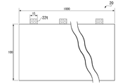
- a positive electrode having 30 15 mm square connecting portions (tab welded portions) on one end side was cut out from the positive electrode roll.
- the length of the positive electrode was 900 mm and the width was 100 mm (FIG. 3A).
- the positive electrode active material (coating film) was scraped off from the connection portion with a cotton swab impregnated with methyl ethyl ketone (MEK).
- the total area of the positive electrode active material was 1.70 ⁇ 10 3 cm 2 .
- “Making a negative electrode” As the negative electrode active material, graphite powder (trade name: MAGE, manufactured by Hitachi Kasei Co., Ltd.) 96.0% by mass, SBR 2.5% by mass, and thickener CMC 1.5% by mass were weighed and dispersed in water. Prepared the slurry. The obtained slurry was applied to both sides on a copper foil having a thickness of 15 ⁇ m. The coating amount was adjusted so that the positive electrode active material layer after drying had a thickness of 20 ⁇ m. Then, it was dried under reduced pressure at a temperature of 140 ° C. for 30 minutes to prepare a negative electrode layer facing the positive electrode active material.
- the other surface was coated with a coating amount of 0.125 g / 1540.25 mm 2 and then dried under reduced pressure at a temperature of 140 ° C. for 30 minutes to form a negative electrode layer facing the positive electrode active material 2.
- a negative electrode roll was obtained by pressing using a roll press apparatus.
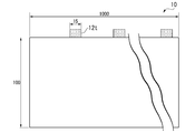
- a negative electrode having 30 15 mm square connecting portions on one end side was cut out from the negative electrode roll.
- the negative electrode 2 had a length of 900 mm and a width of 100 mm (FIG. 3B).
- the negative electrode active material (coating film) was scraped off from the connection portion of the negative electrode with a cotton swab impregnated with MEK to obtain a negative electrode.
- Battery making The battery cell of Example 1 was produced by using the laminate and the non-aqueous electrolytic solution.
- Examples 2 to 32 A battery cell was produced in the same manner as in Example 1 except that the positive electrode was produced with the electrode shapes shown in Table 1. The measurement was carried out in the same manner as in Example 1. The results are shown in Tables 1 and 2.
- Example 33 A positive electrode coated on an aluminum foil having a thickness of 15 ⁇ m so that the thickness of one side of the positive electrode active material layer after drying is 50 ⁇ m, the electrode area of the positive electrode is 3950 mm in length and 145 mm in width, and the width is 4000 mm on one end side. A positive electrode having one connecting portion of the above was cut out. The electrode area of the negative electrode was adjusted to match the positive electrode, the length was 3950 mm and the width was 150 mm, and a negative electrode having one connecting portion having a width of 4000 mm on one end side was cut out.
- Example 34 A positive electrode coated on an aluminum foil having a thickness of 12 ⁇ m so that the thickness of one side of the positive electrode active material layer after drying is 50 ⁇ m, the electrode area of the positive electrode is 4800 mm in length and 310 mm in width, and one end side from the positive electrode roll. A positive electrode having 44 46 mm square connecting portions (tab welded portions) was cut out. The electrode area of the negative electrode was adjusted to match the positive electrode, the length was 4800 mm and the width was 315 mm, and a negative electrode having 44 connecting portions (tab welded portions) having a width of 46 mm square on one end side was cut out.
- Example 35 A positive electrode coated on an aluminum foil having a thickness of 12 ⁇ m so that the thickness of one side of the positive electrode active material layer after drying is 50 ⁇ m is set so that the electrode area of the positive electrode is 1700 mm in length and 56 mm in width, and one end side from the positive electrode roll.
- a positive electrode having four uncoated portions having a side of 13 mm square was cut out.
- Four aluminum tabs (connection portions) having a thickness of 0.1 mm and a width of 4 mm were connected to the uncoated portion as tabs.
- the electrode area of the negative electrode was adjusted to match the positive electrode, the length was 1700 mm and the width was 60 mm, and a negative electrode having four uncoated portions having a side of 13 mm square was cut out.
- Example 36 A positive electrode coated on an aluminum foil having a thickness of 12 ⁇ m so that the thickness of one side of the positive electrode active material layer after drying was 50 ⁇ m was applied to both ends of the coated portion with an electrode area of the positive electrode of 640 mm in length and 56 mm in width. A positive electrode having an uncoated portion of aluminum foil having a length of 50 mm was cut out. One aluminum tab (connection portion) having a thickness of 0.1 mm and a width of 3.0 mm was connected to one end of the uncoated portion as a tab.
- the electrode area of the negative electrode was adjusted to match the positive electrode to have a length of 640 mm and a width of 60 mm, and a negative electrode having uncoated copper foils of 50 mm in length was cut out at both ends of the coated portion.
- Total area Es of the positive electrode active material layer in the above conditions is 717cm 2
- the sum Ts of the cross-sectional area of the distal end of the connecting portion is 0.0030cm 2
- Es / Ts was 2.39 ⁇ 10 5 ..
- Table 3 The results are shown in Table 3.
- Example 37 A positive electrode coated on an aluminum foil having a thickness of 12 ⁇ m so that the thickness of one side of the positive electrode active material layer after drying was 50 ⁇ m was applied to both ends of the coated portion with an electrode area of the positive electrode of 1360 mm in length and 56 mm in width. A positive electrode having an uncoated portion of aluminum foil having a length of 50 mm was cut out. One aluminum tab (connection portion) having a thickness of 0.1 mm and a width of 6.0 mm was connected to one end of the uncoated portion as a tab.
- the electrode area of the negative electrode was adjusted to the positive electrode to have a length of 1360 mm and a width of 60 mm, and a negative electrode having uncoated copper foils of 50 mm in length was cut out at both ends of the coated portion.
- Total area Es of the positive electrode active material layer in the above conditions is 1520 cm 2
- the sum Ts of the cross-sectional area of the distal end of the connecting portion is 0.0060cm 2
- Es / Ts was 2.54 ⁇ 10 5 ..
- Table 3 The results are shown in Table 3.
- Example 38 to 43 Comparative Examples 1 to 7
- Example 38 and Example 39 battery cells were produced under the same conditions as in Example 1, except that the tab width and the number of tabs were changed.
- Example 40 and Example 41 and Comparative Example 4 and Comparative Example 5
- Example 9 battery cells were produced under the same conditions as in Example 9, except that the tab width and the number of tabs were changed.
- Example 42 and Example 43 Comparative Example 1, Comparative Example 6 and Comparative Example 7, battery cells were produced under the same conditions as in Example 16, except that the tab width and the number of tabs were changed. The results are shown in Table 3.
- Example 44 to 50 A battery cell was produced in the same manner as in Example 20 except that graphene or aluminum nitride shown in Table 1 was added to the positive electrode slurry of Example 1. The measurement was carried out in the same manner as in Example 1. The results are shown in Table 4.
- Example 51 to 56 A battery cell was produced in the same manner as in Example 20 except that the heat conductive material layer (DLC, carbon black (CB)) shown in Table 4 was formed on the current collector of Example 20. The measurement was carried out in the same manner as in Example 1. The results are shown in Table 5.
- DLC heat conductive material layer
- CB carbon black
- the heat conductive material layer using DLC was formed on the current collector by the plasma CVD method.
- the heat conductive material layer using carbon black (CB) is a gravure coater containing a slurry containing a predetermined amount of carbon particles (manufactured by Images, trade name Super-P) and a binder (manufactured by Arkema, trade name HSV900) on a current collector. It was applied by the method and formed by heat drying.
- Es / Ts is less than 1.90 ⁇ 10 4, or at high Comparative Examples 1-7 than 2.55 ⁇ 10 5, progress in cycle deterioration. If es / Ts is 1.90 ⁇ 10 4 smaller, it can not be sufficiently release the heat generated positive due to charge-discharge reaction is believed that the deterioration of the positive electrode is promoted. Also, if the Es / Ts is higher than 2.55 ⁇ 10 5, the charge-discharge reaction exotherm of the positive electrode due to heat distribution is generated in the positive electrode inside proceed rapidly in the tab near the region, uneven deterioration in the positive electrode It is probable that the cycle deterioration progressed as a result of the occurrence of.
Abstract
The purpose of the present invention is to provide: a positive electrode which enhances heat dissipation performance during discharge, while having different positive electrode active materials on both surfaces of a positive electrode collector; and a lithium ion secondary battery. A positive electrode according to the present invention comprises a positive electrode collector and an active material layer; and the collector is provided, on at least one surface, with a coated part having an active material layer and an uncoated part having no active material layer. The collector has one or more connection parts, each of which is connected to an external terminal, in the uncoated part. Each of the connection parts has a front end in the external terminal lead-out direction. The positive electrode is characterized in that the total area Es of the active material layer and the sum Ts of the cross-sectional areas of the front ends of the connection parts satisfy the relationship of formula (1). (1): 1.90 × 10⁴ ≤ (Es/Ts) ≤ 2.55 × 10⁵
Description
本発明は、正極及びリチウムイオン二次電池に関する。
本願は、2019年7月12日に、日本に出願された特願2019-130399号に基づき優先権を主張し、その内容をここに援用する。 The present invention relates to a positive electrode and a lithium ion secondary battery.
The present application claims priority based on Japanese Patent Application No. 2019-130399 filed in Japan on July 12, 2019, the contents of which are incorporated herein by reference.
リチウムイオン二次電池は、高容量化を実現することができ、携帯電話やノートパソコン等のモバイルバッテリーから自動車用バッテリーや大型の電力貯蔵用バッテリーまで広く利用されている。
Lithium-ion secondary batteries can achieve high capacity and are widely used from mobile batteries for mobile phones and laptop computers to automobile batteries and large-scale power storage batteries.
リチウムイオン二次電池の電極は集電体に活物質層を塗布された塗布部、活物質層が塗布されない未塗布部を有しており、未塗布部に外部端子を接続する接続部(タブ)が存在する。未塗布部に接続された単一の接続部から外部端子を導出するセル(シングルタブセル)に対して、複数の未塗布部に外部端子を接続する接続部を設けたセル(マルチタブセル)はより高い電流密度での充放電が可能である。
The electrode of the lithium ion secondary battery has a coated portion in which the active material layer is coated on the current collector and an uncoated portion in which the active material layer is not coated, and a connecting portion (tab) for connecting an external terminal to the uncoated portion. ) Exists. A cell (single tab cell) that derives an external terminal from a single connection portion connected to an uncoated portion is a cell (multi-tab cell) that has a connection portion that connects external terminals to a plurality of uncoated portions. It is possible to charge and discharge at a higher current density.
しかしながら、高い電流密度での充放電によって活物質層の劣化が速まり、サイクル特性が低下する課題が生じる。
However, charging / discharging at a high current density accelerates the deterioration of the active material layer, which causes a problem that the cycle characteristics are deteriorated.
本発明は、上記事情に鑑みてなされたものであり、高いサイクル特性が得られるリチウムイオン二次電池用正極及びリチウムイオン二次電池を提供することを目的とする。
The present invention has been made in view of the above circumstances, and an object of the present invention is to provide a positive electrode for a lithium ion secondary battery and a lithium ion secondary battery capable of obtaining high cycle characteristics.
本発明者らは、活物質層の総面積Esと前記接続部の前記先端の断面積の総和Tsの比(Es/Ts)が1.90×104~2.55×105にすることで放電時の放熱性を高め、更に電極の熱伝導性を1.1W/mK以上にすることで更に放熱を促進する事で、残留熱を低減し、サイクル特性を向上することが可能となることを見出した。
すなわち、上記課題を解決するため、以下の手段を提供する。 The present inventors have found that the ratio of the sum Ts of the cross-sectional area of the distal end of the connecting portion to the total area Es of the active material layer (Es / Ts) is a 1.90 × 10 4 ~ 2.55 × 10 5 By improving heat dissipation during discharge and further promoting heat dissipation by increasing the thermal conductivity of the electrode to 1.1 W / mK or more, it is possible to reduce residual heat and improve cycle characteristics. I found that.
That is, in order to solve the above problems, the following means are provided.
[1] 集電体と活物質層を含む正極であって、
前記集電体が、少なくとも一面に活物質層を有する塗布部と、活物質層を有さない未塗布部と、を備え、
前記集電体は、前記未塗布部において、外部端子と接続する接続部を一つ以上有し、 前記接続部が、外部端子導出方向における先端を有し、
前記活物質層の総面積Esと、前記接続部の前記先端の断面積の総和Tsと、が、下記式(1)の関係を満たすことを特徴とする正極。
1.90×10⁴≦(Es/Ts)≦2.55×105 (1)
[2] 前記活物質層における総体積Evが、3.4cm3≦Ev≦300cm3である、[1]に記載の正極。
[3] 前記接続部の前記先端の断面積の総和Tsが、0.003cm2≦Ts≦0.68cm2である、[1]または[2]に記載の正極。
[4] 前記正極の厚み方向における熱伝導率λが、1.1W/mK≦λ≦3.0W/mKである[1]~[3]のいずれかに記載の正極。
[5] [1]~[4]のいずれかに記載の正極と、負極と、前記正極と前記負極とを隔てるセパレータと、電解質とを備える、リチウムイオン二次電池。 [1] A positive electrode including a current collector and an active material layer.
The current collector includes a coated portion having an active material layer on at least one surface and a non-coated portion having no active material layer.
The current collector has one or more connection portions connected to external terminals in the uncoated portion, and the connection portion has a tip in the external terminal lead-out direction.
A positive electrode characterized in that the total area Es of the active material layer and the total Ts of the cross-sectional area of the tip of the connecting portion satisfy the relationship of the following formula (1).
1.90 × 10 4 ≦ (Es / Ts) ≦ 2.55 × 10 5 (1)
[2] The total volume Ev in the active material layer is 3.4cm 3 ≦ Ev ≦ 300cm 3, the positive electrode according to [1].
[3] The positive electrode according to [1] or [2], wherein the total Ts of the cross-sectional area of the tip of the connecting portion is 0.003 cm 2 ≤ Ts ≤ 0.68 cm 2 .
[4] The positive electrode according to any one of [1] to [3], wherein the thermal conductivity λ of the positive electrode in the thickness direction is 1.1 W / mK ≦ λ ≦ 3.0 W / mK.
[5] A lithium ion secondary battery comprising the positive electrode according to any one of [1] to [4], a negative electrode, a separator separating the positive electrode and the negative electrode, and an electrolyte.
本発明にかかる正極によれば、本発明者らは、活物質層の総面積Esと前記接続部の前記先端の断面積の総和Tsの比(Es/Ts)が1.90×104~2.55×105にする事によって、放電時の放熱性を高め、高いサイクル特性が得られる正極及びそれを有するリチウムイオン二次電池を提供することができる。
According to the positive electrode according to the present invention, the present inventors have a ratio (Es / Ts) of the total area Es of the active material layer to the total Ts of the cross-sectional area of the tip of the connecting portion of 1.90 × 10 4 to. by to 2.55 × 10 5, increase the heat radiation at the time of discharge, it is possible to provide a lithium ion secondary battery having a positive electrode and its high cycle characteristics can be obtained.
以下、本実施形態について、図を適宜参照しながら詳細に説明する。以下の説明で用いる図面は、本発明の特徴をわかりやすくするために便宜上特徴となる部分を拡大して示している場合があり、各構成要素の寸法比率などは実際とは異なっていることがある。以下の説明において例示される材料、寸法等は一例であって、本発明はそれらに限定されるものではなく、その要旨を変更しない範囲で適宜変更して実施することが可能である。
Hereinafter, the present embodiment will be described in detail with reference to the figures as appropriate. The drawings used in the following description may be enlarged for convenience in order to make the features of the present invention easy to understand, and the dimensional ratios of the respective components may differ from the actual ones. is there. The materials, dimensions, etc. exemplified in the following description are examples, and the present invention is not limited thereto, and the present invention can be appropriately modified without changing the gist thereof.
[リチウムイオン二次電池]
図1は、本実施形態にかかるリチウムイオン二次電池の断面模式図である。図1に示すリチウムイオン二次電池100は、主として積層体30、積層体30を密閉した状態で収容するケース50、及び積層体30に接続された一対のリード60、62を備えている。また図示されていないが、積層体30とともに電解液が、ケース50内に収容されている。 [Lithium-ion secondary battery]
FIG. 1 is a schematic cross-sectional view of the lithium ion secondary battery according to the present embodiment. The lithium ionsecondary battery 100 shown in FIG. 1 mainly includes a laminate 30, a case 50 that houses the laminate 30 in a sealed state, and a pair of leads 60 and 62 connected to the laminate 30. Although not shown, the electrolytic solution is housed in the case 50 together with the laminated body 30.
図1は、本実施形態にかかるリチウムイオン二次電池の断面模式図である。図1に示すリチウムイオン二次電池100は、主として積層体30、積層体30を密閉した状態で収容するケース50、及び積層体30に接続された一対のリード60、62を備えている。また図示されていないが、積層体30とともに電解液が、ケース50内に収容されている。 [Lithium-ion secondary battery]
FIG. 1 is a schematic cross-sectional view of the lithium ion secondary battery according to the present embodiment. The lithium ion
「積層体」
ケース50内に積層体30は、図1に示すように、正極20、第1負極10-1、第2負極10-2、及びセパレータ18を備える。第1負極10-1又は第2負極10-2は、正極20とが、セパレータ18を挟んで対向配置されたものである。正極と負極の層数が更に増えてもよい。
ここで、本発明の積層体30は、先に形成された一定形状の正極、セパレータ、負極などを、例えば、正極/セパレータ/負極/セパレータの順で積層してなる積層体(「積層体A」ともいう)でもよく、あるいは、図2に示すような巻回体35からなる積層体(「積層体B」ともいう)でもよい。 "Laminate"
As shown in FIG. 1, the laminatedbody 30 includes a positive electrode 20, a first negative electrode 10-1, a second negative electrode 10-2, and a separator 18 in the case 50. The first negative electrode 10-1 or the second negative electrode 10-2 is arranged so that the positive electrode 20 and the positive electrode 20 face each other with the separator 18 interposed therebetween. The number of layers of the positive electrode and the negative electrode may be further increased.
Here, thelaminate 30 of the present invention is a laminate in which the positive electrodes, separators, negative electrodes, etc. of a certain shape previously formed are laminated in the order of, for example, positive electrode / separator / negative electrode / separator (“Laminate body A” , Or a laminated body made of a wound body 35 as shown in FIG. 2 (also referred to as “laminated body B”).
ケース50内に積層体30は、図1に示すように、正極20、第1負極10-1、第2負極10-2、及びセパレータ18を備える。第1負極10-1又は第2負極10-2は、正極20とが、セパレータ18を挟んで対向配置されたものである。正極と負極の層数が更に増えてもよい。
ここで、本発明の積層体30は、先に形成された一定形状の正極、セパレータ、負極などを、例えば、正極/セパレータ/負極/セパレータの順で積層してなる積層体(「積層体A」ともいう)でもよく、あるいは、図2に示すような巻回体35からなる積層体(「積層体B」ともいう)でもよい。 "Laminate"
As shown in FIG. 1, the laminated
Here, the
「正極」
本実施形態の正極は、集電体と活物質層とを含む。前記集電体が、少なくとも一面に活物質層を有する塗布部と、活物質層を有さない未塗布部と、を備える。前記集電体は、前記未塗布部において、外部端子と接続する接続部(「タブ」と言うこともある)を一つ以上有す。前記接続部が、外部端子導出方向における先端を有す。前記活物質層の総面積Esと、前記接続部の前記先端の断面積の総和Tsと、が、下記式(1)の関係を満たすことを特徴とする。 "Positive electrode"
The positive electrode of the present embodiment includes a current collector and an active material layer. The current collector includes a coated portion having an active material layer on at least one surface, and a non-coated portion having no active material layer. The current collector has one or more connecting portions (sometimes referred to as "tabs") connected to external terminals in the uncoated portion. The connection portion has a tip in the direction of leading out the external terminal. The total area Es of the active material layer and the total cross-sectional area Ts of the tip of the connecting portion satisfy the relationship of the following formula (1).
1.90×10⁴≦(Es/Ts)≦2.55×105 (1)
1.90 × 10 4 ≦ (Es / Ts) ≦ 2.55 × 10 5 (1)
前記活物質層の総面積Esと前記接続部の前記先端の断面積の総和Tsとの比(Es/Ts)が、下記式(2)の関係を満たすことが好ましい。
It is preferable that the ratio (Es / Ts) of the total area Es of the active material layer to the total Ts of the cross-sectional area of the tip of the connecting portion satisfies the relationship of the following formula (2).
5.0×10⁴≦(Es/Ts)≦1×105 (2)
5.0 × 10 4 ≦ (Es / Ts) ≦ 1 × 10 5 (2)
ただし、前記先端の断面積が、前記接続部の電流方向と垂直する断面の面積である。 図2に示すように、前記積層体30が巻回体35からなる場合、前記活物質層の総面積をEsは、巻く前の集電体上に活物質層を有する塗布部の総面積である。前記積層体30が電極層から積層してなる場合、前記活物質層の総面積をEsは、各正極集電体層上に活物質層を有する塗布部の面積の総和である。
However, the cross-sectional area of the tip is the area of the cross section perpendicular to the current direction of the connection portion. As shown in FIG. 2, when the laminated body 30 is made of a wound body 35, the total area of the active material layer is defined as the total area of the coating portion having the active material layer on the current collector before winding. is there. When the laminated body 30 is laminated from the electrode layer, the total area of the active material layer is Es, which is the total area of the coating portion having the active material layer on each positive electrode current collector layer.
前記活物質層の総面積と前記接続部の前記先端の断面積の総面積との比(Es/Ts)が1.90×104未満の場合、タブ数が多くなりすぎて巻回後のタブ合わせが難しくなる恐れがあるため、製造上の問題でモノが作りにくくなる、というデメリットがある。2.55×105超える場合、タブ数が少なくなりすぎて所望の特性、例えば出力特性が得られない恐れがあるため、熱溜りによってサイクル劣化が進む、という問題が生じる。なお、前記活物質層の総面積と前記接続部の前記先端の断面積の総面積との比(Es/Ts)のより好ましい範囲は2.5×104~1.0×105であり、より好ましい範囲は3.8×104~9.4×104である。
Wherein if the ratio of the total area of the cross-sectional area of the distal end of the connecting portion to the total area of the active material layer (Es / Ts) is less than 1.90 × 10 4, after the winding too many number of tabs Since tab alignment may be difficult, there is a demerit that it is difficult to make things due to manufacturing problems. 2.55 × 10 5 If it exceeds, the desired properties number of tabs is too small, for example, the output characteristics may not be obtained, cycle deterioration by heat reservoir proceeds, a problem arises. A more preferable range of the ratio of the total area of the cross-sectional area of the distal end of the connecting portion to the total area of the active material layer (Es / Ts) is at 2.5 × 10 4 ~ 1.0 × 10 5 , A more preferable range is 3.8 × 10 4 to 9.4 × 10 4 .
本実施形態の正極において、前記活物質層における総体積Evが、3.4cm3≦Ev≦300cm3であることが好ましく、3.4cm3≦Ev≦34.1cm3であることがより好ましい。
総体積Evが3.4cm3未満の場合、電極厚み或いは面積が小さすぎるため、製造に適してない。総体積Evが300cm3超える場合、電極厚みが厚すぎるため、製造には適しない。 In the positive electrode of the present embodiment, the total volume Ev in the active material layer is preferably from 3.4cm 3 ≦ Ev ≦ 300cm 3, more preferably 3.4cm 3 ≦ Ev ≦ 34.1cm 3.
If the total volume Ev is less than 3.4 cm 3 , the electrode thickness or area is too small, and it is not suitable for manufacturing. If the total volume Ev exceeds 300 cm 3 , the electrode thickness is too thick and it is not suitable for manufacturing.
また、前記接続部の先端の断面積の総和Tsが、0.003cm2≦Ts≦0.68cm2であることがより好ましく、0.003cm2≦Ts≦0.60cm2であることがさらに好ましい。
また、前記接続部の先端の断面積の総和Tsが0.003cm2未満の場合、放熱に必要な十分な熱伝導が確保できず、所望の特性、例えば出力特性が得られない、熱溜りによってサイクル劣化が進む、という問題が生じる。また、Tsが0.68cm2超える場合、タブリードそのものが厚すぎてラミネートフィルムの封止が不十分となり、電解液が漏れるといった可能性がある。なお、前記接続部の先端の断面積の総和Tsの好ましい範囲は0.003~0.60cm2であり、より好ましい範囲は0.005~0.30cm2であり、さらに好ましい範囲は0.015~0.10cm2である。 A sum Ts of the cross-sectional area of the distal end of the connecting portion, more preferably 0.003cm 2 ≦ Ts ≦ 0.68cm 2, further preferably 0.003cm 2 ≦ Ts ≦ 0.60cm 2 ..
Further, when the total cross-sectional area Ts of the tip of the connection portion is less than 0.003 cm 2, sufficient heat conduction required for heat dissipation cannot be secured, and desired characteristics, for example, output characteristics cannot be obtained, due to heat accumulation. There is a problem that cycle deterioration progresses. Further, when Ts exceeds 0.68 cm 2 , the tab lead itself may be too thick to sufficiently seal the laminated film, and the electrolytic solution may leak. The preferable range of the total Ts of the cross-sectional area of the tip of the connecting portion is 0.003 to 0.60 cm 2 , the more preferable range is 0.005 to 0.30 cm 2 , and the more preferable range is 0.015. It is ~ 0.10 cm 2 .
本実施形態の正極の厚み方向における熱伝導率λが、1.1W/mK≦λ≦3.0W/mKであることがさらに好ましい。
λが1.1W/mK未満の場合、放熱に必要な十分な熱伝導が確保できず、所望の特性、例えば出力特性が得られなく、熱溜りによってサイクル劣化が進む,という問題が生じる。また、λが3.0W/mKを超える場合、熱伝導材の添加率を多くなり、その分容量が低下する問題がある。 It is more preferable that the thermal conductivity λ of the positive electrode of the present embodiment in the thickness direction is 1.1 W / mK ≦ λ ≦ 3.0 W / mK.
If λ is less than 1.1 W / mK, there arises a problem that sufficient heat conduction required for heat dissipation cannot be secured, desired characteristics such as output characteristics cannot be obtained, and cycle deterioration progresses due to heat accumulation. Further, when λ exceeds 3.0 W / mK, there is a problem that the addition rate of the heat conductive material increases and the capacity decreases by that amount.
ここで、熱伝導率λは従来公知の「レーザーフラッシュ」法により測定することができる。例えば、レーザーフラッシュ測定装置としては、真空理工製熱定数測定装置TC-7000型を用い、熱伝導率λは下記の式(3)に従って熱容量および電極密度により計算することができる。
λ=αρc (3)
式(3)中において、
λ:熱伝導率(Wm-1K-1)
α:熱拡散率(10-8m2/s)
ρ:電極密度(kg/m3)
c:熱容量(103J/kgK、DSCにより測定することができる。) Here, the thermal conductivity λ can be measured by a conventionally known “laser flash” method. For example, as the laser flash measuring device, a thermal constant measuring device TC-7000 manufactured by Vacuum Riko Co., Ltd. is used, and the thermal conductivity λ can be calculated by the heat capacity and the electrode density according to the following equation (3).
λ = αρc (3)
In equation (3)
λ: Thermal conductivity (Wm -1 K -1 )
α: Thermal diffusivity ( 10-8 m 2 / s)
ρ: Electrode density (kg / m 3 )
c: Heat capacity (10 3 J / kgK, can be measured by DSC)
本実施形態の正極の厚み方向における熱伝導率λは、前記電極において、前記集電体上の活物質層を有する電極部分を測定したものである。集電体の両側に活物質層が塗布される場合、活物質層/集電体/活物質層の順の厚み方向において測定した熱伝導率である。
The thermal conductivity λ of the positive electrode in the thickness direction of the present embodiment is a measurement of the electrode portion having the active material layer on the current collector in the electrode. When the active material layers are applied to both sides of the current collector, the thermal conductivity is measured in the order of thickness of the active material layer / current collector / active material layer.
「正極活物質層」
正極活物質層は正極活物質と正極導電助剤と正極バインダーとを含んでもよい。正極活物質層の厚みが特に限定されなく、例えば、10μm~300μmであることが好ましく、15μm~250μmであることがより好ましい。
<正極活物質>
正極活物質層に用いる正極活物質は、リチウムイオンの吸蔵及び放出、リチウムイオンの脱離及び挿入(インターカレーション)、又は、リチウムイオンとリチウムイオンのカウンターアニオン(例えば、PF6 -)とのドープ及び脱ドープを可逆的に進行させることが可能な電極活物質を用いることができる。 "Positive electrode active material layer"
The positive electrode active material layer may contain a positive electrode active material, a positive electrode conductive auxiliary agent, and a positive electrode binder. The thickness of the positive electrode active material layer is not particularly limited, and is preferably, for example, 10 μm to 300 μm, and more preferably 15 μm to 250 μm.
<Positive electrode active material>
The positive electrode active material used for the positive electrode active material layer, occlusion of lithium ions and release, desorption and insertion of lithium ions (intercalation), or counter anions of the lithium ions and the lithium ions (e.g., PF 6 -) and the An electrode active material capable of reversibly advancing doping and dedoping can be used.
例えば、コバルト酸リチウム(LiCoO2)、ニッケル酸リチウム(LiNiO2)、マンガン酸リチウム(LiMnO2)、リチウムマンガンスピネル(LiMn2O4)、及び、一般式:LiNixCoyMnzMaO2(x+y+z+a=1、0≦x<1、0≦y<1、0≦z<1、0≦a<1、MはAl、Mg、Nb、Ti、Cu、Zn、Crより選ばれる1種類以上の元素)で表される複合金属酸化物;リチウムバナジウム化合物(LiV2O5、LiVOPO4、Li3V2(PO4)3)、オリビン型LiMPO4(ただし、Mは、Co、Ni、Mn、Fe、Mg、Nb、Ti、Al、Zrより選ばれる1種類以上の元素)、チタン酸リチウム(Li4Ti5O12)、LiNixCoyAlzO2(0.9<x+y+z<1.1)等の複合金属酸化物;ポリアセチレン、ポリアニリン、ポリピロール、ポリチオフェン等の導電性ポリマー系材料;ポリアセン等のカーボン系材料などが挙げられる。
For example, lithium cobalt oxide (LiCoO 2), lithium nickelate (LiNiO 2), lithium manganate (LiMnO 2), lithium manganese spinel (LiMn 2 O 4), and the general formula: LiNi x Co y Mn z M a O 2 (x + y + z + a = 1, 0 ≦ x <1, 0 ≦ y <1, 0 ≦ z <1, 0 ≦ a <1, M is one type selected from Al, Mg, Nb, Ti, Cu, Zn, Cr. Composite metal oxides represented by the above elements); lithium vanadium compounds (LiV 2 O 5 , LiVOPO 4 , Li 3 V 2 (PO 4 ) 3 ), olivine type LiMPO 4 (where M is Co, Ni, Mn, Fe, Mg, Nb, Ti, Al, 1 or more elements selected from Zr), lithium titanate (Li 4 Ti 5 O 12) , LiNi x Co y Al z O 2 (0.9 <x + y + z < 1.1) and the like composite metal oxides; conductive polymer materials such as polyacetylene, polyaniline, polypyrrole, polythiophene; carbon materials such as polyacene and the like.
<正極導電助剤>
導電助剤は、例えば、カーボンブラック類等のカーボン粉末、カーボンナノチューブ、多層グラフェンなどの炭素材料が挙げられる。これらの中でも、カーボンブラック等の炭素材料が好ましい。
多層グラフェンが更に好ましい。グラフェンが含まれることで、前記電極の熱伝導率が高くなるができる。 <Positive electrode conductive aid>
Examples of the conductive auxiliary agent include carbon powders such as carbon blacks, carbon nanotubes, and carbon materials such as multilayer graphene. Among these, a carbon material such as carbon black is preferable.
Multilayer graphene is more preferred. The inclusion of graphene can increase the thermal conductivity of the electrode.
<熱伝導性材料>
正極活物質層が、さらに熱伝導性材料を含んでもよい。例えば、熱伝導性材料である窒化アルミニウム(AlN)粉末、窒化ホウ素(BN)粉末などが挙げられる。熱伝導性材料の添加量は、正極活物質層に対して、0.5~10質量%であることが好ましい。その範囲で熱伝導性材料を含む場合、電極の熱伝導率が高くなることができる同時に、電極の電気特性に悪い影響を受けないことができる。 <Thermal conductive material>
The positive electrode active material layer may further contain a thermally conductive material. For example, aluminum nitride (AlN) powder and boron nitride (BN) powder, which are thermally conductive materials, can be mentioned. The amount of the heat conductive material added is preferably 0.5 to 10% by mass with respect to the positive electrode active material layer. When a heat conductive material is included in that range, the thermal conductivity of the electrode can be increased, and at the same time, the electrical characteristics of the electrode can be not adversely affected.
<正極バインダー>
バインダーは、活物質同士を結合すると共に、活物質と負極集電体12とを結合する。バインダーは、上述の結合が可能なものであればよく、例えば、ポリフッ化ビニリデン(PVDF)、ポリテトラフルオロエチレン(PTFE)、テトラフルオロエチレン-ヘキサフルオロプロピレン共重合体(FEP)、テトラフルオロエチレン-パーフルオロアルキルビニルエーテル共重合体(PFA)、エチレン-テトラフルオロエチレン共重合体(ETFE)、ポリクロロトリフルオロエチレン(PCTFE)、エチレン-クロロトリフルオロエチレン共重合体(ECTFE)、ポリフッ化ビニル(PVF)等のフッ素樹脂が挙げられる。 <Positive binder>
The binder binds the active materials to each other and also binds the active material to the negative electrode current collector 12. The binder may be any one capable of the above-mentioned binding, for example, polyvinyl fluoride (PVDF), polytetrafluoroethylene (PTFE), tetrafluoroethylene-hexafluoropropylene copolymer (FEP), tetrafluoroethylene-. Perfluoroalkyl vinyl ether copolymer (PFA), ethylene-tetrafluoroethylene copolymer (ETFE), polychlorotrifluoroethylene (PCTFE), ethylene-chlorotrifluoroethylene copolymer (ECTFE), polyvinyl fluoride (PVF) ) And other fluororesins.
また、上記の他に、バインダーとして、例えば、ビニリデンフルオライド-ヘキサフルオロプロピレン系フッ素ゴム(VDF-HFP系フッ素ゴム)、ビニリデンフルオライド-ヘキサフルオロプロピレン-テトラフルオロエチレン系フッ素ゴム(VDF-HFP-TFE系フッ素ゴム)、ビニリデンフルオライド-ペンタフルオロプロピレン系フッ素ゴム(VDF-PFP系フッ素ゴム)、ビニリデンフルオライド-ペンタフルオロプロピレン-テトラフルオロエチレン系フッ素ゴム(VDF-PFP-TFE系フッ素ゴム)、ビニリデンフルオライド-パーフルオロメチルビニルエーテル-テトラフルオロエチレン系フッ素ゴム(VDF-PFMVE-TFE系フッ素ゴム)、ビニリデンフルオライド-クロロトリフルオロエチレン系フッ素ゴム(VDF-CTFE系フッ素ゴム)等のビニリデンフルオライド系フッ素ゴムを用いてもよい。
In addition to the above, as binders, for example, vinylidene fluoride-hexafluoropropylene fluororubber (VDF-HFP fluoropolymer), vinylidene fluoride-hexafluoropropylene-tetrafluoroethylene fluororubber (VDF-HFP-) TFE-based fluororubber), vinylidene fluoride-pentafluoropropylene-based fluororubber (VDF-PFP-based fluororubber), vinylidene fluoride-pentafluoropropylene-tetrafluoroethylene-based fluororubber (VDF-PFP-TFE-based fluororubber), Vinylidene fluoride-perfluoromethyl vinyl ether-tetrafluoroethylene fluororubber (VDF-PFMVE-TFE fluororubber), vinylidene fluoride-chlorotrifluoroethylene fluoropolymer (VDF-CTFE fluororubber), etc. A fluororubber may be used.
また、バインダーとして電子伝導性の導電性高分子やイオン伝導性の導電性高分子を用いてもよい。電子伝導性の導電性高分子としては、例えば、ポリアセチレン等が挙げられる。この場合は、バインダーが導電助剤の機能も発揮するので導電助剤を添加しなくてもよい。イオン伝導性の導電性高分子としては、例えば、リチウムイオン等のイオンの伝導性を有するものを使用することができ、例えば、高分子化合物(ポリエチレンオキシド、ポリプロピレンオキシド等のポリエーテル系高分子化合物、ポリフォスファゼン等)のモノマーと、LiClO4、LiBF4、LiPF6等のリチウム塩又はリチウムを主体とするアルカリ金属塩と、を複合化させたもの等が挙げられる。複合化に使用する重合開始剤としては、例えば、上記のモノマーに適合する光重合開始剤または熱重合開始剤が挙げられる。
Further, an electron conductive conductive polymer or an ionic conductive polymer may be used as the binder. Examples of the electron-conducting conductive polymer include polyacetylene and the like. In this case, since the binder also functions as a conductive auxiliary agent, it is not necessary to add the conductive auxiliary agent. As the ionic conductive polymer, for example, one having ionic conductivity such as lithium ion can be used, and for example, a polymer compound (polyether-based polymer compound such as polyethylene oxide and polypropylene oxide) can be used. , Polyphosphazene, etc.) and a lithium salt such as LiClO 4 , LiBF 4 , LiPF 6 or an alkali metal salt mainly composed of lithium, and the like. Examples of the polymerization initiator used for the complexing include a photopolymerization initiator or a thermal polymerization initiator compatible with the above-mentioned monomers.
またこの他に、バインダーとして、例えば、セルロース、スチレン・ブタジエンゴム、エチレン・プロピレンゴム、ポリイミド樹脂、ポリアミドイミド樹脂、アクリル樹脂等を用いてもよい。
In addition to this, for example, cellulose, styrene / butadiene rubber, ethylene / propylene rubber, polyimide resin, polyamide-imide resin, acrylic resin or the like may be used as the binder.
正極活物質層における正極活物質の構成比率は、質量比で80%以上90%以下であることが好ましい。また正極活物質層24A、24Bにおける導電助剤の構成比率は、質量比で0.5%以上10%以下であることが好ましく、正極活物質層におけるバインダーの構成比率は、質量比で0.5%以上10%以下であることが好ましい。
The composition ratio of the positive electrode active material in the positive electrode active material layer is preferably 80% or more and 90% or less in terms of mass ratio. The composition ratio of the conductive auxiliary agent in the positive electrode active material layers 24A and 24B is preferably 0.5% or more and 10% or less in terms of mass ratio, and the composition ratio of the binder in the positive electrode active material layer is 0. It is preferably 5% or more and 10% or less.
「正極集電体」
正極集電体22は、導電性の板材であればよく、例えば、アルミニウム、銅、ニッケル箔の金属薄板を用いることができる。正極集電体22の厚みは、特に限定されないが、8~30μmであることが好ましい。 "Positive current collector"
The positive electrodecurrent collector 22 may be any conductive plate material, and for example, a thin metal plate of aluminum, copper, or nickel foil can be used. The thickness of the positive electrode current collector 22 is not particularly limited, but is preferably 8 to 30 μm.
正極集電体22は、導電性の板材であればよく、例えば、アルミニウム、銅、ニッケル箔の金属薄板を用いることができる。正極集電体22の厚みは、特に限定されないが、8~30μmであることが好ましい。 "Positive current collector"
The positive electrode
<正極接続部>
正極集電体22は、活物質層を有する塗布部と、活物質層を有さない未塗布部を備える。この未塗布部の少なくとも一部に、外部端子と接続する接続部22tを一つ以上有する。 <Positive electrode connection>
The positive electrodecurrent collector 22 includes a coated portion having an active material layer and a non-coated portion having no active material layer. At least a part of the uncoated portion has one or more connecting portions 22t to be connected to the external terminal.
正極集電体22は、活物質層を有する塗布部と、活物質層を有さない未塗布部を備える。この未塗布部の少なくとも一部に、外部端子と接続する接続部22tを一つ以上有する。 <Positive electrode connection>
The positive electrode
「熱伝導材料層」
本実施形態のリチウムイオン二次電池の正極は、前記正極集電体と正極活物質層の間にさらにカーボン層などからなる熱伝導材料層(図示なし)を含んでもよい。 "Heat conductive material layer"
The positive electrode of the lithium ion secondary battery of the present embodiment may further include a heat conductive material layer (not shown) composed of a carbon layer or the like between the positive electrode current collector and the positive electrode active material layer.
カーボン層は、カーボン粒子とバインダーとからなるものでもよい。カーボン粒子としては、例えば、カーボンブラック、アセチレンブラック、グラフェン、黒鉛が挙げられる。バインダーとして、ポリフッ化ビニリデン(PVDF)が挙げられる。カーボン層に対して、カーボン粒子の含有量が95質量%以上であることが好ましく、95%以上であることがより好ましい。
The carbon layer may be composed of carbon particles and a binder. Examples of carbon particles include carbon black, acetylene black, graphene, and graphite. Examples of the binder include polyvinylidene fluoride (PVDF). The content of carbon particles is preferably 95% by mass or more, more preferably 95% or more, based on the carbon layer.
カーボン層は導電性を有し、3次元に結合した炭素結合を有することが好ましい。
すなわち、カーボン層は、sp2混成軌道による炭素結合と、sp3混成軌道による炭素結合と、の両方を炭素元素の基本骨格として結晶構造内に有することが好ましい。 The carbon layer is conductive and preferably has a three-dimensionally bonded carbon bond.
That is, it is preferable that the carbon layer has both a carbon bond by the sp 2 hybrid orbital and a carbon bond by the sp 3 hybrid orbital in the crystal structure as the basic skeleton of the carbon element.
このようなカーボン層は、例えば、ダイヤモンドライクカーボン(DLC)の炭素の結合状態を示したDLC膜、グラファイトの炭素の結合状態を示したグラファイト膜、アセチレンブラック膜などが挙げられる。
Examples of such a carbon layer include a DLC film showing a carbon-bonded state of diamond-like carbon (DLC), a graphite film showing a carbon-bonded state of graphite, and an acetylene black film.
また、熱伝導材料層として、カーボン層以外にも、窒化アルミニウム膜等の窒化物を用いてもよい。
Further, as the heat conductive material layer, a nitride such as an aluminum nitride film may be used in addition to the carbon layer.
これらの熱伝導材料層は単層で用いてもよく、複層で用いてもよい。また、単層中に炭素材料、窒化物を複数種混合して用いてもよい。
These heat conductive material layers may be used as a single layer or as multiple layers. Further, a plurality of types of carbon materials and nitrides may be mixed and used in the single layer.
熱伝導率が高い観点から、DLC膜が好ましい。
A DLC film is preferable from the viewpoint of high thermal conductivity.
熱伝導材料層の厚みは1nm~1.5μmであることが好ましく、1nm~1.0μmであることがより好ましい。
The thickness of the heat conductive material layer is preferably 1 nm to 1.5 μm, more preferably 1 nm to 1.0 μm.
「負極」
本実施形態のリチウムイオン二次電池の負極は、第1負極10-1と第2負極10-2で構成されている。第1負極10-1は、第1負極活物質層14-1と第1負極集電体12-1とからなり、第2負極10-2は、第2負極活物質層14-2と第1負極集電体12-2とからなる。第1負極活物質層14-1は、第1負極活物質と導電助剤とバインダーとを含み、第2負極活物質層14-2は、第2負極活物質と導電助剤とバインダーとを含む。本実施形態のリチウムイオン二次電池において、同じ種類の正極活物質層に対して同じ種類の負極活物質層が隣接していることが好ましい。図1に示す本実施形態の一例では、第1負極活物質層と前記第2負極活物質層は厚みが異なることが好ましい。 "Negative electrode"
The negative electrode of the lithium ion secondary battery of the present embodiment is composed of a first negative electrode 10-1 and a second negative electrode 10-2. The first negative electrode 10-1 is composed of a first negative electrode active material layer 14-1 and a first negative electrode current collector 12-1, and the second negative electrode 10-2 is a second negative electrode active material layer 14-2 and a first negative electrode active material layer 14-2. 1 Consists of a negative electrode current collector 12-2. The first negative electrode active material layer 14-1 contains a first negative electrode active material, a conductive auxiliary agent, and a binder, and the second negative electrode active material layer 14-2 contains a second negative electrode active material, a conductive auxiliary agent, and a binder. Including. In the lithium ion secondary battery of the present embodiment, it is preferable that the same type of negative electrode active material layer is adjacent to the same type of positive electrode active material layer. In the example of the present embodiment shown in FIG. 1, it is preferable that the first negative electrode active material layer and the second negative electrode active material layer have different thicknesses.
「負極集電体」
負極集電体12(12-1、12-2)は、導電性の板材であればよく、例えば、銅、ニッケル箔の金属薄板を用いることができる。負極集電体12は、リチウムと合金化しないことが好ましく、銅が特に好ましい。負極集電体12の厚みは4~30μmとすることが好ましい。 "Negative electrode current collector"
The negative electrode current collector 12 (12-1, 12-2) may be a conductive plate material, and for example, a thin metal plate of copper or nickel foil can be used. The negative electrode current collector 12 is preferably not alloyed with lithium, and copper is particularly preferable. The thickness of the negative electrode current collector 12 is preferably 4 to 30 μm.
<負極接続部>
負極集電体12は、活物質層を有する塗布部と、活物質層を有さない未塗布部を備える。この未塗布部の少なくとも一部に、外部端子と接続する負極接続部12tを一つ以上有する。 <Negative electrode connection>
The negative electrode current collector 12 includes a coated portion having an active material layer and an uncoated portion having no active material layer. At least a part of the uncoated portion has one or more negativeelectrode connecting portions 12t connected to the external terminal.
負極集電体12は、活物質層を有する塗布部と、活物質層を有さない未塗布部を備える。この未塗布部の少なくとも一部に、外部端子と接続する負極接続部12tを一つ以上有する。 <Negative electrode connection>
The negative electrode current collector 12 includes a coated portion having an active material layer and an uncoated portion having no active material layer. At least a part of the uncoated portion has one or more negative
「負極活物質層」
第1負極活物質層14-1と第2負極活物質層14-2は、負極活物質と負極バインダーとを有し、必要に応じて導電助剤を有する。第1負極活物質層14-1と第2負極活物質層14-2は同じ負極活物質を含むことが好ましい。 "Negative electrode active material layer"
The first negative electrode active material layer 14-1 and the second negative electrode active material layer 14-2 have a negative electrode active material and a negative electrode binder, and if necessary, have a conductive auxiliary agent. The first negative electrode active material layer 14-1 and the second negative electrode active material layer 14-2 preferably contain the same negative electrode active material.
「負極活物質」
負極活物質はリチウムイオンを吸蔵・放出可能な化合物であればよく、公知のリチウムイオン二次電池用の負極活物質を使用できる。負極活物質としては、例えば、リチウムイオンを吸蔵・放出可能な黒鉛(天然黒鉛、人造黒鉛)、カーボンナノチューブ、難黒鉛化炭素、易黒鉛化炭素、低温度焼成炭素等の炭素材料、アルミニウム、シリコン、スズ等のリチウムと化合することのできる金属、二酸化シリコン、二酸化スズ等の酸化物を主体とする非晶質の化合物、チタン酸リチウム(Li4Ti5O12)等を含む粒子が挙げられる。単位重量あたりの容量の高く、比較的安定な黒鉛を用いることが好ましい。 "Negative electrode active material"
The negative electrode active material may be any compound that can occlude and release lithium ions, and a known negative electrode active material for a lithium ion secondary battery can be used. Examples of the negative electrode active material include carbon materials such as graphite (natural graphite, artificial graphite) capable of storing and releasing lithium ions, carbon nanotubes, non-graphitizable carbon, easily graphitized carbon, and low-temperature calcined carbon, aluminum, and silicon. , Metals that can be combined with lithium such as tin, silicon dioxide, amorphous compounds mainly composed of oxides such as tin dioxide, particles containing lithium titanate (Li 4 Ti 5 O 12 ) and the like. .. It is preferable to use graphite having a high capacity per unit weight and being relatively stable.
「負極導電助剤」
導電助剤としては、例えば、カーボンブラック類等のカーボン粉末、カーボンナノチューブ、炭素材料、銅、ニッケル、ステンレス、鉄等の金属微粉、炭素材料及び金属微粉の混合物、ITO等の導電性酸化物が挙げられる。これらの中でも、アセチレンブラックやエチレンブラック等のカーボン粉末が特に好ましい。負極活物質のみで十分な導電性を確保できる場合は、リチウムイオン二次電池100は導電助剤を含んでいなくてもよい。 "Negative electrode conductive auxiliary agent"
Examples of the conductive auxiliary agent include carbon powder such as carbon black, carbon nanotubes, carbon material, metal fine powder such as copper, nickel, stainless steel and iron, a mixture of carbon material and metal fine powder, and conductive oxide such as ITO. Can be mentioned. Among these, carbon powders such as acetylene black and ethylene black are particularly preferable. When sufficient conductivity can be ensured only by the negative electrode active material, the lithium ionsecondary battery 100 does not have to contain a conductive auxiliary agent.
導電助剤としては、例えば、カーボンブラック類等のカーボン粉末、カーボンナノチューブ、炭素材料、銅、ニッケル、ステンレス、鉄等の金属微粉、炭素材料及び金属微粉の混合物、ITO等の導電性酸化物が挙げられる。これらの中でも、アセチレンブラックやエチレンブラック等のカーボン粉末が特に好ましい。負極活物質のみで十分な導電性を確保できる場合は、リチウムイオン二次電池100は導電助剤を含んでいなくてもよい。 "Negative electrode conductive auxiliary agent"
Examples of the conductive auxiliary agent include carbon powder such as carbon black, carbon nanotubes, carbon material, metal fine powder such as copper, nickel, stainless steel and iron, a mixture of carbon material and metal fine powder, and conductive oxide such as ITO. Can be mentioned. Among these, carbon powders such as acetylene black and ethylene black are particularly preferable. When sufficient conductivity can be ensured only by the negative electrode active material, the lithium ion
「負極バインダー」
負極に用いるバインダーは正極と同様のものを使用できる。 "Negative electrode binder"
The binder used for the negative electrode can be the same as that used for the positive electrode.
負極に用いるバインダーは正極と同様のものを使用できる。 "Negative electrode binder"
The binder used for the negative electrode can be the same as that used for the positive electrode.
「セパレータ」
セパレータ18は、電気絶縁性の多孔質構造から形成されていればよく、例えば、ポリエチレン、ポリプロピレン又はポリオレフィンからなるフィルムの単層体、積層体や上記樹脂の混合物の延伸膜、或いはセルロース、ポリエステル及びポリプロピレンからなる群より選択される少なくとも1種の構成材料からなる繊維不織布が挙げられる。 "Separator"
Theseparator 18 may be formed from an electrically insulating porous structure, for example, a monolayer of a film made of polyethylene, polypropylene or polyolefin, a laminate or a stretched film of a mixture of the above resins, or cellulose, polyester and Examples thereof include fibrous nonwoven fabrics made of at least one constituent material selected from the group consisting of polypropylene.
セパレータ18は、電気絶縁性の多孔質構造から形成されていればよく、例えば、ポリエチレン、ポリプロピレン又はポリオレフィンからなるフィルムの単層体、積層体や上記樹脂の混合物の延伸膜、或いはセルロース、ポリエステル及びポリプロピレンからなる群より選択される少なくとも1種の構成材料からなる繊維不織布が挙げられる。 "Separator"
The
「電解液」
電解液には、リチウム塩を含む電解質溶液(電解質水溶液、有機溶媒を使用する電解質溶液)を使用することができる。ただし、電解質水溶液は電気化学的に分解電圧が低いため、充電時の耐用電圧が低く制限される。そのため、有機溶媒を使用する電解質溶液(非水電解質溶液)であることが好ましい。 "Electrolytic solution"
As the electrolytic solution, an electrolyte solution containing a lithium salt (an aqueous electrolyte solution, an electrolyte solution using an organic solvent) can be used. However, since the decomposition voltage of the aqueous electrolyte solution is electrochemically low, the withstand voltage during charging is low and limited. Therefore, it is preferable to use an electrolyte solution (non-aqueous electrolyte solution) that uses an organic solvent.
非水電解液は、非水溶媒に電解質が溶解されており、非水溶媒として環状カーボネートと、鎖状カーボネートと、を含有してもよい。
The non-aqueous electrolyte solution has an electrolyte dissolved in a non-aqueous solvent, and may contain a cyclic carbonate and a chain carbonate as the non-aqueous solvent.
環状カーボネートとしては、電解質を溶媒和することができるものを用いることができる。例えば、エチレンカーボネート、プロピレンカーボネート及びブチレンカーボネートなどを用いることができる。
As the cyclic carbonate, one that can solvate the electrolyte can be used. For example, ethylene carbonate, propylene carbonate, butylene carbonate and the like can be used.
鎖状カーボネートは、環状カーボネートの粘性を低下させることができる。例えば、ジエチルカーボネート、ジメチルカーボネート、エチルメチルカーボネートが挙げられる。その他、酢酸メチル、酢酸エチル、プロピオン酸メチル、プロピオン酸エチル、γ-ブチロラクトン、1,2-ジメトキシエタン、1,2-ジエトキシエタンなどを混合して使用してもよい。
Chain carbonate can reduce the viscosity of cyclic carbonate. For example, diethyl carbonate, dimethyl carbonate, ethyl methyl carbonate can be mentioned. In addition, methyl acetate, ethyl acetate, methyl propionate, ethyl propionate, γ-butyrolactone, 1,2-dimethoxyethane, 1,2-diethoxyethane and the like may be mixed and used.
非水溶媒中の環状カーボネートと鎖状カーボネートの割合は体積にして1:9~1:1にすることが好ましい。
The ratio of cyclic carbonate to chain carbonate in the non-aqueous solvent is preferably 1: 9 to 1: 1 in volume.
電解質としては、例えば、LiPF6、LiClO4、LiBF4、LiCF3SO3、LiCF3CF2SO3、LiC(CF3SO2)3、LiN(CF3SO2)2、LiN(CF3CF2SO2)2、LiN(CF3SO2)(C4F9SO2)、LiN(CF3CF2CO)2、LiBOB等のリチウム塩が使用できる。なお、これらのリチウム塩は1種を単独で使用してもよく、2種以上を併用してもよい。特に、電離度の観点から、LiPF6を含むことが好ましい。
Examples of the electrolyte include LiPF 6 , LiClO 4 , LiBF 4 , LiCF 3 SO 3 , LiCF 3 CF 2 SO 3 , LiC (CF 3 SO 2 ) 3 , LiN (CF 3 SO 2 ) 2 , and LiN (CF 3 CF). 2 SO 2 ) 2 , LiN (CF 3 SO 2 ) (C 4 F 9 SO 2 ), LiN (CF 3 CF 2 CO) 2 , LiBOB and other lithium salts can be used. One of these lithium salts may be used alone, or two or more thereof may be used in combination. In particular, from the viewpoint of the degree of ionization, it is preferable to contain LiPF 6 .
LiPF6を非水溶媒に溶解する際は、非水電解液中の電解質の濃度を、0.5~2.0mol/Lに調整することが好ましい。電解質の濃度が0.5mol/L以上であると、非水電解液のリチウムイオン濃度を充分に確保することができ、充放電時に十分な容量が得られやすい。また、電解質の濃度が2.0mol/L以内に抑えることで、非水電解液の粘度上昇を抑え、リチウムイオンの移動度を充分に確保することができ、充放電時に十分な容量が得られやすくなる。
When dissolving LiPF 6 in a non-aqueous solvent, it is preferable to adjust the concentration of the electrolyte in the non-aqueous electrolyte solution to 0.5 to 2.0 mol / L. When the concentration of the electrolyte is 0.5 mol / L or more, the lithium ion concentration of the non-aqueous electrolyte solution can be sufficiently secured, and a sufficient capacity can be easily obtained during charging / discharging. Further, by suppressing the concentration of the electrolyte to 2.0 mol / L or less, it is possible to suppress the increase in the viscosity of the non-aqueous electrolyte solution, to sufficiently secure the mobility of lithium ions, and to obtain a sufficient capacity during charging and discharging. It will be easier.
LiPF6をその他の電解質と混合する場合にも、非水電解液中のリチウムイオン濃度が0.5~2.0mol/Lに調整することが好ましく、LiPF6からのリチウムイオン濃度がその50mol%以上含まれることがさらに好ましい。
Even when LiPF 6 is mixed with other electrolytes, it is preferable to adjust the lithium ion concentration in the non-aqueous electrolyte solution to 0.5 to 2.0 mol / L, and the lithium ion concentration from LiPF 6 is 50 mol% thereof. It is more preferable to include the above.
「ケース」
ケース50は、その内部に積層体30及び電解液を密封するものである。ケース50は、電解液の外部への漏出や、外部からのリチウムイオン二次電池100内部への水分等の侵入等を抑止できる物であれば特に限定されない。 "Case"
Thecase 50 seals the laminate 30 and the electrolytic solution inside the case 50. The case 50 is not particularly limited as long as it can suppress leakage of the electrolytic solution to the outside and invasion of water or the like into the inside of the lithium ion secondary battery 100 from the outside.
ケース50は、その内部に積層体30及び電解液を密封するものである。ケース50は、電解液の外部への漏出や、外部からのリチウムイオン二次電池100内部への水分等の侵入等を抑止できる物であれば特に限定されない。 "Case"
The
例えば、ケース50として、図1に示すように、金属箔52を高分子膜54で両側からコーティングした金属ラミネートフィルムを利用できる。金属箔52としては例えばアルミ箔を、高分子膜54としてはポリプロピレン等の膜を利用できる。例えば、外側の高分子膜54の材料としては融点の高い高分子、例えば、ポリエチレンテレフタレート(PET)、ポリアミド等が好ましく、内側の高分子膜54の材料としてはポリエチレン(PE)、ポリプロピレン(PP)等が好ましい。
For example, as the case 50, as shown in FIG. 1, a metal laminate film in which a metal foil 52 is coated with a polymer film 54 from both sides can be used. For example, an aluminum foil can be used as the metal foil 52, and a film such as polypropylene can be used as the polymer film 54. For example, the material of the outer polymer film 54 is preferably a polymer having a high melting point, for example, polyethylene terephthalate (PET) or polyamide, and the material of the inner polymer film 54 is polyethylene (PE) or polypropylene (PP). Etc. are preferable.
「リード」
リード62、60は、アルミ等の導電材料から形成されている。そして、公知の方法により、リード62、60を正極集電体22の接続部22t、負極集電体12の接続部12tにそれぞれ溶接し、正極20の第1正極活物質層24Aと第1負極10-1の第1負極活物質層14-1との間にセパレータ18を挟み、正極20の第2正極活物質層24Bと第2負極10-2の第2負極活物質層14-2との間にセパレータ18を挟んだ状態で、電解液と共にケース50内に挿入し、ケース50の入り口をシールする。 "Lead"
The leads 62 and 60 are made of a conductive material such as aluminum. Then, the leads 62 and 60 are welded to the connecting portion 22t of the positive electrode current collector 22 and the connecting portion 12t of the negative electrode current collector 12 by a known method, respectively, and the first positive electrode active material layer 24A and the first negative electrode of the positive electrode 20 are welded to each other. A separator 18 is sandwiched between the first negative electrode active material layer 14-1 of 10-1, and the second positive electrode active material layer 24B of the positive electrode 20 and the second negative electrode active material layer 14-2 of the second negative electrode 10-2. With the separator 18 sandwiched between the two, the separator 18 is inserted into the case 50 together with the electrolytic solution to seal the entrance of the case 50.
リード62、60は、アルミ等の導電材料から形成されている。そして、公知の方法により、リード62、60を正極集電体22の接続部22t、負極集電体12の接続部12tにそれぞれ溶接し、正極20の第1正極活物質層24Aと第1負極10-1の第1負極活物質層14-1との間にセパレータ18を挟み、正極20の第2正極活物質層24Bと第2負極10-2の第2負極活物質層14-2との間にセパレータ18を挟んだ状態で、電解液と共にケース50内に挿入し、ケース50の入り口をシールする。 "Lead"
The leads 62 and 60 are made of a conductive material such as aluminum. Then, the
[正極及びリチウムイオン二次電池の製造方法]
本実施形態にかかる正極及びリチウムイオン二次電池の製造方法について説明する。 [Manufacturing method of positive electrode and lithium ion secondary battery]
A method for manufacturing a positive electrode and a lithium ion secondary battery according to the present embodiment will be described.
本実施形態にかかる正極及びリチウムイオン二次電池の製造方法について説明する。 [Manufacturing method of positive electrode and lithium ion secondary battery]
A method for manufacturing a positive electrode and a lithium ion secondary battery according to the present embodiment will be described.
まず第1正極活物質、バインダー及び溶媒を混合する。必要に応じ前述の導電助剤、熱伝導性材料を更に加えても良い。溶媒としては例えば、水、N-メチル-2-ピロリドン等を用いることができる。塗料を構成する成分の混合方法は特に制限されず、混合順序もまた特に制限されない。上記第1正極活物質層24Aの形成用塗料を、正極の集電体22の第1面に塗布する。塗布方法としては、特に制限はなく、通常電極を作製する場合に採用される方法を用いることができる。例えば、スリットダイコート法、ドクターブレード法が挙げられる。同様に、第2正極活物質層24Bの形成用塗料を調整し、正極の集電体22の第2面に塗布する。また、必要に応じ集電体と活物質層との間に前述の熱伝導材料層(カーボン層)を形成してもよい。
First, the first positive electrode active material, the binder and the solvent are mixed. If necessary, the above-mentioned conductive aid and thermally conductive material may be further added. As the solvent, for example, water, N-methyl-2-pyrrolidone and the like can be used. The method of mixing the components constituting the paint is not particularly limited, and the mixing order is also not particularly limited. The coating material for forming the first positive electrode active material layer 24A is applied to the first surface of the current collector 22 of the positive electrode. The coating method is not particularly limited, and a method usually adopted when producing an electrode can be used. For example, the slit die coat method and the doctor blade method can be mentioned. Similarly, the coating material for forming the second positive electrode active material layer 24B is prepared and applied to the second surface of the positive electrode current collector 22. Further, if necessary, the above-mentioned heat conductive material layer (carbon layer) may be formed between the current collector and the active material layer.
負極についても、第1負極の負極集電体12-1の少なくとも一方の面に塗料を所定の量で塗布し、第2負極の負極集電体12-2の少なくとも一方の面に塗料を所定の量で塗布する。
As for the negative electrode, a predetermined amount of paint is applied to at least one surface of the negative electrode current collector 12-1 of the first negative electrode, and the paint is prescribed to at least one surface of the negative electrode current collector 12-2 of the second negative electrode. Apply in the amount of.
続いて、正極集電体22及び負極集電体12上に塗布された塗料中の溶媒を除去する。除去方法は特に限定されない。例えば、塗料が塗布された正極集電体22及び負極集電体12を、80℃~150℃の雰囲気下で乾燥させればよい。そして、第1正極活物質層24Aと第2正極活物質層24Bとを有する正極20、少なくとも一方の面に第1負極活物質層14-1を有する第1負極10-1及び少なくとも一方の面に第2負極活物質層14-2を有する第2負極10-2を作成する。
Subsequently, the solvent in the paint applied on the positive electrode current collector 22 and the negative electrode current collector 12 is removed. The removal method is not particularly limited. For example, the positive electrode current collector 22 and the negative electrode current collector 12 coated with the paint may be dried in an atmosphere of 80 ° C. to 150 ° C. Then, the positive electrode 20 having the first positive electrode active material layer 24A and the second positive electrode active material layer 24B, the first negative electrode 10-1 having the first negative electrode active material layer 14-1 on at least one surface, and at least one surface. A second negative electrode 10-2 having a second negative electrode active material layer 14-2 is prepared.
そして、このようにして第1正極活物質層24Aと第2正極活物質層24Bとが形成された正極20、少なくとも1面に第1負極活物質層14-1が形成された第1負極10-1及び少なくとも1面に第2負極活物質層14-2が形成された第2負極10-2を必要に応じ、ロールプレス装置等によりプレス処理を行う。ロールプレスの線圧は用いる材料によって異なるが、第1正極活物質層24Aと第2正極活物質層24Bの密度がそれぞれの所定の値となるように調整する。第1正極活物質層24Aと第2正極活物質層24Bのそれぞれの密度と線圧との関係は、事前検討により求めることができる。
Then, the positive electrode 20 on which the first positive electrode active material layer 24A and the second positive electrode active material layer 24B are formed in this way, and the first negative electrode 10 on which the first negative electrode active material layer 14-1 is formed on at least one surface. -1 and the second negative electrode 10-2 having the second negative electrode active material layer 14-2 formed on at least one surface thereof are pressed, if necessary, by a roll press device or the like. The linear pressure of the roll press varies depending on the material used, but is adjusted so that the densities of the first positive electrode active material layer 24A and the second positive electrode active material layer 24B have their respective predetermined values. The relationship between the density and the linear pressure of each of the first positive electrode active material layer 24A and the second positive electrode active material layer 24B can be obtained by prior examination.
次いで、第1負極10-1/セパレータ18/正極20/セパレータ18/第2負極10-2の順になるように、正極20と、第1負極10-1と、第2負極10-2と、第1負極と正極との間、及び、正極と第2負極との間に介在するセパレータ18と、イオン液体と、をケース50内に封入する。
Next, the positive electrode 20, the first negative electrode 10-1, and the second negative electrode 10-2 are arranged in the order of the first negative electrode 10-1 / separator 18 / positive electrode 20 / separator 18 / second negative electrode 10-2. The separator 18 interposed between the first negative electrode and the positive electrode and between the positive electrode and the second negative electrode and the ionic liquid are sealed in the case 50.
例えば、第1負極10-1と、セパレータ18と、正極20と、セパレータ18と、第2負極10-2を積層し、正極及び負極を、積層方向に対して垂直な方向から、プレス器具で加熱加圧し、第1負極10-1と、セパレータ18と、正極20と、セパレータ18と、第2負極10-2とを密着させる。そして、例えば、予め作製した袋状のケース50に、積層体30を入れる。
For example, the first negative electrode 10-1, the separator 18, the positive electrode 20, the separator 18, and the second negative electrode 10-2 are laminated, and the positive electrode and the negative electrode are pressed from a direction perpendicular to the stacking direction with a press instrument. By heating and pressurizing, the first negative electrode 10-1 and the separator 18, the positive electrode 20, the separator 18 and the second negative electrode 10-2 are brought into close contact with each other. Then, for example, the laminated body 30 is placed in a bag-shaped case 50 prepared in advance.
図2に示す巻回体35を用いる場合、作製した正極20及び負極10の間にセパレータ18を配設し、また、巻きこむ際に外側となる部分にもセパレータを配設する。そして、正極20、負極10及びセパレータ18の一端側を軸として、これらを巻回する。
When the winding body 35 shown in FIG. 2 is used, the separator 18 is arranged between the produced positive electrode 20 and the negative electrode 10, and the separator is also arranged on the outer portion when the wound body 35 is wound. Then, the positive electrode 20, the negative electrode 10, and the separator 18 are wound around one end side as an axis.
最後に、巻回体35を外装体ケース50内に封入する。非水電解液は外装体50内に注入する。非水電解液を注入後に減圧、加熱等を行うことで、巻回体内に非水電解液が含浸する。外装体50は、熱等を加えて封止する。
Finally, the winding body 35 is enclosed in the outer body case 50. The non-aqueous electrolyte solution is injected into the exterior body 50. The non-aqueous electrolyte is impregnated in the wound body by depressurizing, heating, etc. after injecting the non-aqueous electrolyte. The exterior body 50 is sealed by applying heat or the like.
以上、本発明の実施形態について図面を参照して詳述したが、各実施形態における各構成及びそれらの組み合わせ等は一例であり、本発明の趣旨から逸脱しない範囲内で、構成の付加、省略、置換、及びその他の変更が可能である。
Although the embodiments of the present invention have been described in detail with reference to the drawings, the configurations and combinations thereof in the respective embodiments are examples, and the configurations are added or omitted within the range not deviating from the gist of the present invention. , Replacement, and other changes are possible.
(実施例1)
「正極の作製」
正極活物質には、NCA:リチウム・ニッケル・コバルト・アルミニウム複合酸化物(LiNi0.83Co0.12Al0.05O2)を用いた。上記正極活物質を96.0質量%と、導電助剤としてカーボンブラック(商品名:Super-P;Imerys製)を1.5質量%と、バインダーとしてポリフッ化ビニリデン(PVDF)を2.5質量%と、をそれぞれ秤量し、N-メチル-2-ピロリドン(NMP)中に分散させ、スラリーを調製した。得られたスラリーを厚さ15μmのアルミ箔上の両面に塗布した。塗布量は、乾燥後の正極活物質層片面の厚みが20μmになるように、調整した。その後、温度140℃で30分間乾燥することで正極活物質層を作製した。その後、ロールプレス装置を用いてプレス処理することにより、正極ロールを得た。 (Example 1)
"Preparation of positive electrode"
As the positive electrode active material, NCA: lithium-nickel-cobalt-aluminum composite oxide (LiNi 0.83 Co 0.12 Al 0.05 O 2 ) was used. The positive electrode active material is 96.0% by mass, carbon black (trade name: Super-P; manufactured by Imerys) is 1.5% by mass as a conductive auxiliary agent, and polyvinylidene fluoride (PVDF) is 2.5% by mass as a binder. % And, respectively, were weighed and dispersed in N-methyl-2-pyrrolidone (NMP) to prepare a slurry. The obtained slurry was applied to both sides on an aluminum foil having a thickness of 15 μm. The coating amount was adjusted so that the thickness of one side of the positive electrode active material layer after drying was 20 μm. Then, the positive electrode active material layer was prepared by drying at a temperature of 140 ° C. for 30 minutes. Then, a positive electrode roll was obtained by pressing using a roll press apparatus.
そして、正極ロールから一端側に15mm角の接続部(タブ溶接箇所)30個を有する正極を切り出した。正極の長さは900mm、幅は100mmであった(図3A)。接続部から正極活物質(塗膜)を、メチルエチルケトン(MEK)を染み込ませた綿棒で擦り剥がした。正極活物質の総面積は1.70×103cm2であった。
Then, a positive electrode having 30 15 mm square connecting portions (tab welded portions) on one end side was cut out from the positive electrode roll. The length of the positive electrode was 900 mm and the width was 100 mm (FIG. 3A). The positive electrode active material (coating film) was scraped off from the connection portion with a cotton swab impregnated with methyl ethyl ketone (MEK). The total area of the positive electrode active material was 1.70 × 10 3 cm 2 .
「負極の作製」
負極活物質として黒鉛粉末(商品名MAGE、日立化成株式会社製)96.0質量%と、SBR 2.5質量%と、増粘剤CMC 1.5質量%をそれぞれ秤量し、水中に分散させてスラリーを調製した。得られたスラリーを厚さ15μmの銅箔上の両面に塗布した。塗布量は、乾燥後の正極活物質層が厚み20μmになるように、調整した。その後温度140℃で30分間減圧乾燥することで正極活物質に対向する負極層を作製した。もう一方の面は0.125g/1540.25mm2の塗布量で塗布し、その後温度140℃で30分間減圧乾燥することで正極活物質2に対向する負極層とした。その後、ロールプレス装置を用いてプレス処理することにより、負極ロールを得た。
負極ロールから一端側に15mm角の接続部30個を有する負極を切り出した。負極2の長さは900mm、幅は100mmであった(図3B)。そして負極の接続部から負極活物質(塗膜)を、MEKを染み込ませた綿棒で擦り剥がし、負極を得た。 "Making a negative electrode"
As the negative electrode active material, graphite powder (trade name: MAGE, manufactured by Hitachi Kasei Co., Ltd.) 96.0% by mass, SBR 2.5% by mass, and thickener CMC 1.5% by mass were weighed and dispersed in water. Prepared the slurry. The obtained slurry was applied to both sides on a copper foil having a thickness of 15 μm. The coating amount was adjusted so that the positive electrode active material layer after drying had a thickness of 20 μm. Then, it was dried under reduced pressure at a temperature of 140 ° C. for 30 minutes to prepare a negative electrode layer facing the positive electrode active material. The other surface was coated with a coating amount of 0.125 g / 1540.25 mm 2 and then dried under reduced pressure at a temperature of 140 ° C. for 30 minutes to form a negative electrode layer facing the positive electrode active material 2. Then, a negative electrode roll was obtained by pressing using a roll press apparatus.
A negative electrode having 30 15 mm square connecting portions on one end side was cut out from the negative electrode roll. The negative electrode 2 had a length of 900 mm and a width of 100 mm (FIG. 3B). Then, the negative electrode active material (coating film) was scraped off from the connection portion of the negative electrode with a cotton swab impregnated with MEK to obtain a negative electrode.
「セパレータの作製」
膜厚20μmのポリエチレン微多孔膜(空孔率:40%、シャットダウン温度:134℃)を用意した。このセパレータを長さ1100mm、幅80mmに切り出した。 "Making a separator"
A polyethylene microporous membrane having a film thickness of 20 μm (vacancy ratio: 40%, shutdown temperature: 134 ° C.) was prepared. This separator was cut out to a length of 1100 mm and a width of 80 mm.
(巻回体の作製)
セパレータを2枚用意し揃えて重ねた。そして、これらの間に負極をセパレータの先端から5mmのところに負極10の一端がくるように重ねた。また正極20は、負極10の一端から5mmのところに正極20の一端がくるように重ねた。すなわち、巻回体35の最外周となる側の一端には、141mm幅でセパレータ18のみからなる最外周部が形成された。 (Making a wound body)
Two separators were prepared and aligned and stacked. Then, a negative electrode was placed between them so that one end of thenegative electrode 10 was located 5 mm from the tip of the separator. Further, the positive electrode 20 was stacked so that one end of the positive electrode 20 was located 5 mm from one end of the negative electrode 10. That is, at one end of the winding body 35 on the outermost peripheral side, an outermost peripheral portion having a width of 141 mm and composed of only the separator 18 was formed.
セパレータを2枚用意し揃えて重ねた。そして、これらの間に負極をセパレータの先端から5mmのところに負極10の一端がくるように重ねた。また正極20は、負極10の一端から5mmのところに正極20の一端がくるように重ねた。すなわち、巻回体35の最外周となる側の一端には、141mm幅でセパレータ18のみからなる最外周部が形成された。 (Making a wound body)
Two separators were prepared and aligned and stacked. Then, a negative electrode was placed between them so that one end of the
幅65mm、厚み3mmのSUS板に、これらを巻きつけて巻回体35を得た。セパレータの最外周端は、テープで留めて固定した。セパレータ18は負極10の終端部から1周さらに巻回されている。最後に、タブ部分にリードを超音波溶接で付け、巻回体35を作製した。リードは正極がAl、負極がNiを用いた。
These were wound around a SUS plate having a width of 65 mm and a thickness of 3 mm to obtain a wound body 35. The outermost peripheral end of the separator was fixed with tape. The separator 18 is further wound around the end of the negative electrode 10. Finally, a lead was attached to the tab portion by ultrasonic welding to prepare a wound body 35. As the lead, Al was used for the positive electrode and Ni was used for the negative electrode.
「非水電解質溶液の調製」
電解質としてエチレンカーボネート(EC)とジエチルカーボネート(DEC)の混合溶媒に、LiPF6を1.5mol/Lとなるように溶解させた非水電解質溶液を用意した。混合溶媒におけるECとDECとの体積比は、EC:DEC=30:70とした。 "Preparation of non-aqueous electrolyte solution"
A non-aqueous electrolyte solution in which LiPF 6 was dissolved at 1.5 mol / L in a mixed solvent of ethylene carbonate (EC) and diethyl carbonate (DEC) as an electrolyte was prepared. The volume ratio of EC to DEC in the mixed solvent was EC: DEC = 30: 70.
「電池の作製」
上記積層体と上記非水電解液とを用いて、実施例1の電池セルを作製した。 "Battery making"
The battery cell of Example 1 was produced by using the laminate and the non-aqueous electrolytic solution.
上記積層体と上記非水電解液とを用いて、実施例1の電池セルを作製した。 "Battery making"
The battery cell of Example 1 was produced by using the laminate and the non-aqueous electrolytic solution.
「サイクル特性の測定」
0.1Cの定電流密度で充電終止電圧が4.2V(vs.Li/Li+)になるまで充電を行い、さらに4.2V(vs.Li/Li+)の定電圧で電流値が0.05Cの電流密度に低下するまで定電圧充電を行った。その後10分間休止し、1Cの定電流密度で放電終止電圧が2.8V(vs.Li/Li+)になるまで放電し1Cの容量を得た。その後、充電においても1Cにし、それ以外は同じ条件で充放電を500回繰り返し行った。500サイクル後の放電容量を測定し、500サイクル後の放電容量を初期の放電容量で除することで得られる容量維持率を算出することでサイクル特性を評価した。このときの容量維持率は88%であった。
評価結果を表1に示す。 "Measurement of cycle characteristics"
Charging is performed at a constant current density of 0.1 C until the final charging voltage reaches 4.2 V (vs. Li / Li + ), and the current value is 0 at a constant voltage of 4.2 V (vs. Li / Li + ). Constant voltage charging was performed until the current density decreased to 0.05C. After that, it was rested for 10 minutes and discharged at a constant current density of 1C until the discharge end voltage became 2.8V (vs. Li / Li + ) to obtain a capacity of 1C. After that, charging was also set to 1C, and charging and discharging were repeated 500 times under the same conditions other than that. The cycle characteristics were evaluated by measuring the discharge capacity after 500 cycles and calculating the capacity retention rate obtained by dividing the discharge capacity after 500 cycles by the initial discharge capacity. The capacity retention rate at this time was 88%.
The evaluation results are shown in Table 1.
[電極熱伝導率の測定]
前記作成した正極の一部をレーザーフラッシュ法により電極熱伝導率を測定した。結果を表1に示す。 [Measurement of electrode thermal conductivity]
The electrode thermal conductivity of a part of the prepared positive electrode was measured by a laser flash method. The results are shown in Table 1.
前記作成した正極の一部をレーザーフラッシュ法により電極熱伝導率を測定した。結果を表1に示す。 [Measurement of electrode thermal conductivity]
The electrode thermal conductivity of a part of the prepared positive electrode was measured by a laser flash method. The results are shown in Table 1.

(実施例2~32)
表1に示す電極形状で正極を作成した以外は、実施例1と同様に電池セルを作製した。実施例1と同様に測定した。その結果を表1と表2に示す。 (Examples 2 to 32)
A battery cell was produced in the same manner as in Example 1 except that the positive electrode was produced with the electrode shapes shown in Table 1. The measurement was carried out in the same manner as in Example 1. The results are shown in Tables 1 and 2.

(実施例33)
厚み15μmのアルミニウム箔に、塗布量は、乾燥後の正極活物質層片面の厚みが50μmとなるように塗布した正極を、正極の電極面積を長さ3950mm、幅145mmとし、一端側に幅4000mmの接続部を1個有する正極を切り出した。
負極の電極面積を正極に合わせ、長さ3950mm、幅150mmとし、一端側に幅4000mmの接続部を1個有する負極を切り出した。
上記条件における正極活物質層の総面積Esは11460cm2であり、前記接続部の前記先端の断面積の総和Tsは0.59cm2であり、Es/Tsは1.93×104であった。その結果を表3に示す。 (Example 33)
A positive electrode coated on an aluminum foil having a thickness of 15 μm so that the thickness of one side of the positive electrode active material layer after drying is 50 μm, the electrode area of the positive electrode is 3950 mm in length and 145 mm in width, and the width is 4000 mm on one end side. A positive electrode having one connecting portion of the above was cut out.
The electrode area of the negative electrode was adjusted to match the positive electrode, the length was 3950 mm and the width was 150 mm, and a negative electrode having one connecting portion having a width of 4000 mm on one end side was cut out.
Total area Es of the positive electrode active material layer in the above conditions is 11460cm 2, the sum Ts of the cross-sectional area of the distal end of the connecting portion is 0.59 cm 2, Es / Ts was 1.93 × 10 4 .. The results are shown in Table 3.
(実施例34)
厚み12μmのアルミニウム箔に、塗布量は、乾燥後の正極活物質層片面の厚みが50μmとなるように塗布した正極を、正極の電極面積を長さ4800mm、幅310mmとし、正極ロールから一端側に46mm角の接続部(タブ溶接箇所)44個を有する正極を切り出した。
負極の電極面積を正極に合わせ、長さ4800mm、幅315mmとし、一端側に幅46mm角の接続部(タブ溶接箇所)44個を有する負極を切り出した。
上記条件における正極活物質層の総面積Esは29800cm2であり、前記接続部の前記先端の断面積の総和Tsは0.24cm2であり、Es/Tsは1.22×105であった。その結果を表3に示す。 (Example 34)
A positive electrode coated on an aluminum foil having a thickness of 12 μm so that the thickness of one side of the positive electrode active material layer after drying is 50 μm, the electrode area of the positive electrode is 4800 mm in length and 310 mm in width, and one end side from the positive electrode roll. A positive electrode having 44 46 mm square connecting portions (tab welded portions) was cut out.
The electrode area of the negative electrode was adjusted to match the positive electrode, the length was 4800 mm and the width was 315 mm, and a negative electrode having 44 connecting portions (tab welded portions) having a width of 46 mm square on one end side was cut out.
Total area Es of the positive electrode active material layer in the above conditions is 29800cm 2, the sum Ts of the cross-sectional area of the distal end of the connecting portion is 0.24 cm 2, Es / Ts was 1.22 × 10 5 .. The results are shown in Table 3.
(実施例35)
厚み12μmのアルミニウム箔に、塗布量は、乾燥後の正極活物質層片面の厚みが50μmとなるように塗布した正極を、正極の電極面積を長さ1700mm、幅56mmとし、正極ロールから一端側に一辺が13mm四方の未塗布部を4個有する正極を切り出した。この未塗布部にタブとして厚み0.1mm、幅4mmのアルミニウムタブ(接続部)を4個接続した。
負極の電極面積を正極に合わせ、長さ1700mm、幅60mmとし、一辺が13mm四方の未塗布部を4個有する負極を切り出した。この未塗布部にタブとして厚み0.1mm、幅4.0mmのニッケルタブを4個接続した。
上記条件における正極活物質層の総面積Esは1890cm2であり、前記接続部の前記先端の断面積の総和Tsは0.016cm2であり、Es/Tsは1.18×105であった。その結果を表3に示す。 (Example 35)
A positive electrode coated on an aluminum foil having a thickness of 12 μm so that the thickness of one side of the positive electrode active material layer after drying is 50 μm is set so that the electrode area of the positive electrode is 1700 mm in length and 56 mm in width, and one end side from the positive electrode roll. A positive electrode having four uncoated portions having a side of 13 mm square was cut out. Four aluminum tabs (connection portions) having a thickness of 0.1 mm and a width of 4 mm were connected to the uncoated portion as tabs.
The electrode area of the negative electrode was adjusted to match the positive electrode, the length was 1700 mm and the width was 60 mm, and a negative electrode having four uncoated portions having a side of 13 mm square was cut out. Four nickel tabs having a thickness of 0.1 mm and a width of 4.0 mm were connected to the uncoated portion as tabs.
Total area Es of the positive electrode active material layer in the above conditions is 1890 2, the sum Ts of the cross-sectional area of the distal end of the connecting portion is 0.016 cm 2, Es / Ts was 1.18 × 10 5 .. The results are shown in Table 3.
(実施例36)
厚み12μmのアルミニウム箔に、塗布量は、乾燥後の正極活物質層片面の厚みが50μmとなるように塗布した正極を、正極の電極面積を長さ640mm、幅56mmとし、塗布部の両端にそれぞれ未塗布部のアルミニウム箔を長さ50mm有する正極を切り出した。未塗布部の一端にタブとして厚み0.1mm、幅3.0mmのアルミニウムタブ(接続部)を1個接続した。
負極の電極面積を正極に合わせ、長さ640mm、幅60mmとし、塗布部の両端にそれぞれ未塗布部の銅箔を長さ50mm有する負極を切り出した。
上記条件における正極活物質層の総面積Esは717cm2であり、前記接続部の前記先端の断面積の総和Tsは0.0030cm2であり、Es/Tsは2.39×105であった。その結果を表3に示す。 (Example 36)
A positive electrode coated on an aluminum foil having a thickness of 12 μm so that the thickness of one side of the positive electrode active material layer after drying was 50 μm was applied to both ends of the coated portion with an electrode area of the positive electrode of 640 mm in length and 56 mm in width. A positive electrode having an uncoated portion of aluminum foil having a length of 50 mm was cut out. One aluminum tab (connection portion) having a thickness of 0.1 mm and a width of 3.0 mm was connected to one end of the uncoated portion as a tab.
The electrode area of the negative electrode was adjusted to match the positive electrode to have a length of 640 mm and a width of 60 mm, and a negative electrode having uncoated copper foils of 50 mm in length was cut out at both ends of the coated portion.
Total area Es of the positive electrode active material layer in the above conditions is 717cm 2, the sum Ts of the cross-sectional area of the distal end of the connecting portion is 0.0030cm 2, Es / Ts was 2.39 × 10 5 .. The results are shown in Table 3.
(実施例37)
厚み12μmのアルミニウム箔に、塗布量は、乾燥後の正極活物質層片面の厚みが50μmとなるように塗布した正極を、正極の電極面積を長さ1360mm、幅56mmとし、塗布部の両端にそれぞれ未塗布部のアルミニウム箔を長さ50mm有する正極を切り出した。未塗布部の一端にタブとして厚み0.1mm、幅6.0mmのアルミニウムタブ(接続部)を1個接続した。
負極の電極面積を正極に合わせ、長さ1360mm、幅60mmとし、塗布部の両端にそれぞれ未塗布部の銅箔を長さ50mm有する負極を切り出した。
上記条件における正極活物質層の総面積Esは1520cm2であり、前記接続部の前記先端の断面積の総和Tsは0.0060cm2であり、Es/Tsは2.54×105であった。その結果を表3に示す。 (Example 37)
A positive electrode coated on an aluminum foil having a thickness of 12 μm so that the thickness of one side of the positive electrode active material layer after drying was 50 μm was applied to both ends of the coated portion with an electrode area of the positive electrode of 1360 mm in length and 56 mm in width. A positive electrode having an uncoated portion of aluminum foil having a length of 50 mm was cut out. One aluminum tab (connection portion) having a thickness of 0.1 mm and a width of 6.0 mm was connected to one end of the uncoated portion as a tab.
The electrode area of the negative electrode was adjusted to the positive electrode to have a length of 1360 mm and a width of 60 mm, and a negative electrode having uncoated copper foils of 50 mm in length was cut out at both ends of the coated portion.
Total area Es of the positive electrode active material layer in the above conditions is 1520 cm 2, the sum Ts of the cross-sectional area of the distal end of the connecting portion is 0.0060cm 2, Es / Ts was 2.54 × 10 5 .. The results are shown in Table 3.
(実施例38~43、比較例1~7)
タブ幅とタブ数を変更したことを除いて、実施例38および実施例39、比較例2および比較例3は実施例1と同様の条件で電池セルを作製した。
タブ幅とタブ数を変更したことを除いて、実施例40および実施例41、比較例4および比較例5は実施例9と同様の条件で電池セルを作製した。
タブ幅とタブ数を変更したことを除いて、実施例42および実施例43、比較例1、比較例6および比較例7は実施例16と同様の条件で電池セルを作製した。その結果を表3に示す。 (Examples 38 to 43, Comparative Examples 1 to 7)
In Example 38 and Example 39, and Comparative Example 2 and Comparative Example 3, battery cells were produced under the same conditions as in Example 1, except that the tab width and the number of tabs were changed.
In Example 40 and Example 41, and Comparative Example 4 and Comparative Example 5, battery cells were produced under the same conditions as in Example 9, except that the tab width and the number of tabs were changed.
In Example 42 and Example 43, Comparative Example 1, Comparative Example 6 and Comparative Example 7, battery cells were produced under the same conditions as in Example 16, except that the tab width and the number of tabs were changed. The results are shown in Table 3.

(実施例44~50)
実施例1の正極スラリーに表1に示すグラフェン又は窒化アルミを添加し以外は、実施例20と同様に電池セルを作製した。実施例1と同様に測定した。その結果を表4に示す。 (Examples 44 to 50)
A battery cell was produced in the same manner as in Example 20 except that graphene or aluminum nitride shown in Table 1 was added to the positive electrode slurry of Example 1. The measurement was carried out in the same manner as in Example 1. The results are shown in Table 4.

(実施例51~56)
実施例20の集電体に、表4に示す熱伝導材料層(DLC、カーボンブラック(CB))を形成した以外は、実施例20と同様に電池セルを作製した。実施例1と同様に測定した。その結果を表5に示す。 (Examples 51 to 56)
A battery cell was produced in the same manner as in Example 20 except that the heat conductive material layer (DLC, carbon black (CB)) shown in Table 4 was formed on the current collector of Example 20. The measurement was carried out in the same manner as in Example 1. The results are shown in Table 5.
DLCを用いた熱伝導材料層はプラズマCVD法により集電体上に製膜した。
カーボンブラック(CB)を用いた熱伝導材料層は、集電体上に所定量の炭素粒子(Imerys製造、商品名Super-P)とバインダー(Arkema製造、商品名HSV900)を含むスラリーをグラビアコーター法により塗布し、加熱乾燥によって形成された。 The heat conductive material layer using DLC was formed on the current collector by the plasma CVD method.
The heat conductive material layer using carbon black (CB) is a gravure coater containing a slurry containing a predetermined amount of carbon particles (manufactured by Images, trade name Super-P) and a binder (manufactured by Arkema, trade name HSV900) on a current collector. It was applied by the method and formed by heat drying.

表1~表5に示す通り、Es/Tsが1.90×104より小さく、あるいは、2.55×105より高い比較例1~7において、サイクル劣化が進んだ。Es/Tsが1.90×104より小さい場合、充放電反応による正極の発熱を十分に放出することができず、正極の劣化が促進されるためと考えられる。また、Es/Tsが2.55×105より高い場合、充放電反応による正極の発熱が、タブ付近領域において急速に進むことで正極内部に熱分布が発生し、正極内において不均一な劣化が生じる結果、サイクル劣化が進んだためと考えられる。
As shown in Tables 1 to 5, Es / Ts is less than 1.90 × 10 4, or at high Comparative Examples 1-7 than 2.55 × 10 5, progress in cycle deterioration. If es / Ts is 1.90 × 10 4 smaller, it can not be sufficiently release the heat generated positive due to charge-discharge reaction is believed that the deterioration of the positive electrode is promoted. Also, if the Es / Ts is higher than 2.55 × 10 5, the charge-discharge reaction exotherm of the positive electrode due to heat distribution is generated in the positive electrode inside proceed rapidly in the tab near the region, uneven deterioration in the positive electrode It is probable that the cycle deterioration progressed as a result of the occurrence of.
10、10-1、10-2…負極、
12、12-1、12-2…負極集電体、
12t…負極接続部、
14-1、14-2…負極活物質層、
18…セパレータ、
20…正極、
22…正極集電体、
22t…正極接続部、
24、24A、24-2B…正極活物質層、
30…積層体、
35…巻回体、
50…ケース、
60、62…リード、
100…リチウムイオン二次電池。 10, 10-1, 10-2 ... Negative electrode,
12, 12-1, 12-2 ... Negative electrode current collector,
12t ... Negative electrode connection,
14-1, 14-2 ... Negative electrode active material layer,
18 ... Separator,
20 ... Positive electrode,
22 ... Positive electrode current collector,
22t ... Positive electrode connection,
24, 24A, 24-2B ... Positive electrode active material layer,
30 ... Laminate,
35 ... Winder,
50 ... case,
60, 62 ... lead,
100 ... Lithium ion secondary battery.
Claims (5)
- 集電体と活物質層を含む正極であって、
前記集電体が、少なくとも一面に活物質層を有する塗布部と、活物質層を有さない未塗布部と、を備え、
前記集電体は、前記未塗布部において、外部端子と接続する接続部を一つ以上有し、前記接続部が、外部端子導出方向における先端を有し、
前記活物質層の総面積Esと、前記接続部の前記先端の断面積の総和Tsと、が、下記式(1)の関係を満たすことを特徴とする正極。
1.90×10⁴≦(Es/Ts)≦2.55×105 (1) A positive electrode containing a current collector and an active material layer.
The current collector includes a coated portion having an active material layer on at least one surface and a non-coated portion having no active material layer.
The current collector has one or more connection portions connected to external terminals in the uncoated portion, and the connection portion has a tip in the external terminal lead-out direction.
A positive electrode characterized in that the total area Es of the active material layer and the total Ts of the cross-sectional area of the tip of the connecting portion satisfy the relationship of the following formula (1).
1.90 × 10 4 ≦ (Es / Ts) ≦ 2.55 × 10 5 (1) - 前記活物質層における総体積Evが、3.4cm3≦Ev≦300cm3である、請求項1に記載の正極。 The total volume Ev in the active material layer is 3.4cm 3 ≦ Ev ≦ 300cm 3, the positive electrode of claim 1.
- 前記接続部の前記先端の断面積の総和Tsが、0.003cm2≦Ts≦0.68cm2である、請求項1または2に記載の正極。 The positive electrode according to claim 1 or 2, wherein the total Ts of the cross-sectional areas of the tips of the connecting portions is 0.003 cm 2 ≤ Ts ≤ 0.68 cm 2 .
- 前記正極の厚み方向における熱伝導率λが、1.1W/mK≦λ≦3.1W/mKである請求項1~3のいずれか一項に記載の正極。 The positive electrode according to any one of claims 1 to 3, wherein the thermal conductivity λ of the positive electrode in the thickness direction is 1.1 W / mK ≦ λ ≦ 3.1 W / mK.
- 請求項1~4のいずれか一項に記載の正極と、負極と、前記正極と前記負極とを隔てるセパレータと、電解質とを備える、リチウムイオン二次電池。 A lithium ion secondary battery comprising the positive electrode according to any one of claims 1 to 4, a negative electrode, a separator separating the positive electrode and the negative electrode, and an electrolyte.
Applications Claiming Priority (2)
| Application Number | Priority Date | Filing Date | Title |
|---|---|---|---|
| JP2019130399 | 2019-07-12 | ||
| JP2019-130399 | 2019-07-12 |
Publications (1)
| Publication Number | Publication Date |
|---|---|
| WO2021010185A1 true WO2021010185A1 (en) | 2021-01-21 |
Family
ID=74209799
Family Applications (1)
| Application Number | Title | Priority Date | Filing Date |
|---|---|---|---|
| PCT/JP2020/026133 WO2021010185A1 (en) | 2019-07-12 | 2020-07-03 | Positive electrode and lithium ion secondary battery |
Country Status (1)
| Country | Link |
|---|---|
| WO (1) | WO2021010185A1 (en) |
Citations (4)
| Publication number | Priority date | Publication date | Assignee | Title |
|---|---|---|---|---|
| JP2010135170A (en) * | 2008-12-04 | 2010-06-17 | Hitachi Vehicle Energy Ltd | Lithium secondary battery, secondary battery module, and secondary battery pack |
| JP2010257811A (en) * | 2009-04-27 | 2010-11-11 | Panasonic Corp | Secondary battery |
| WO2017047353A1 (en) * | 2015-09-14 | 2017-03-23 | 日立マクセル株式会社 | Nonaqueous electrolyte secondary battery |
| JP2018142420A (en) * | 2017-02-27 | 2018-09-13 | 住友大阪セメント株式会社 | Electrode for lithium ion secondary battery and lithium ion secondary battery |
-
2020
- 2020-07-03 WO PCT/JP2020/026133 patent/WO2021010185A1/en active Application Filing
Patent Citations (4)
| Publication number | Priority date | Publication date | Assignee | Title |
|---|---|---|---|---|
| JP2010135170A (en) * | 2008-12-04 | 2010-06-17 | Hitachi Vehicle Energy Ltd | Lithium secondary battery, secondary battery module, and secondary battery pack |
| JP2010257811A (en) * | 2009-04-27 | 2010-11-11 | Panasonic Corp | Secondary battery |
| WO2017047353A1 (en) * | 2015-09-14 | 2017-03-23 | 日立マクセル株式会社 | Nonaqueous electrolyte secondary battery |
| JP2018142420A (en) * | 2017-02-27 | 2018-09-13 | 住友大阪セメント株式会社 | Electrode for lithium ion secondary battery and lithium ion secondary battery |
Similar Documents
| Publication | Publication Date | Title |
|---|---|---|
| JP6995738B2 (en) | Positive electrode for lithium-ion secondary battery and lithium-ion secondary battery | |
| JP7115296B2 (en) | Negative electrode and lithium ion secondary battery | |
| JP2018174070A (en) | Lithium ion secondary battery | |
| JP6946694B2 (en) | Lithium ion secondary battery | |
| JP6981027B2 (en) | Negative electrode active material for lithium ion secondary battery, negative electrode and lithium ion secondary battery | |
| JP2019164965A (en) | Lithium ion secondary battery | |
| JP2019164964A (en) | Negative electrode for lithium ion secondary battery and lithium ion secondary battery | |
| JP7003775B2 (en) | Lithium ion secondary battery | |
| JP7064709B2 (en) | Negative negative for lithium ion secondary battery and lithium ion secondary battery | |
| JP2018170142A (en) | Lithium ion secondary battery | |
| JP2018160379A (en) | Negative electrode for lithium ion secondary battery and lithium ion secondary battery | |
| JP6237777B2 (en) | Negative electrode active material, negative electrode using the same, and lithium ion secondary battery | |
| JP7069938B2 (en) | Positive electrode for lithium-ion secondary battery and lithium-ion secondary battery using it | |
| JP7020167B2 (en) | Non-aqueous electrolyte secondary battery | |
| US20210083316A1 (en) | Secondary cell with nonaqueous electrolyte | |
| JP6855882B2 (en) | Positive electrode and lithium ion secondary battery | |
| JP2018174110A (en) | Current collector and lithium ion secondary battery | |
| WO2021010185A1 (en) | Positive electrode and lithium ion secondary battery | |
| JP7243381B2 (en) | Electrodes and non-aqueous electrolyte secondary batteries | |
| JP7087532B2 (en) | Negative negative for lithium ion secondary battery and lithium ion secondary battery | |
| JP7017108B2 (en) | Active materials, electrodes and lithium-ion secondary batteries | |
| JP6128228B2 (en) | Negative electrode active material, negative electrode using the same, and lithium ion secondary battery | |
| JP6904393B2 (en) | Method for manufacturing negative electrode for lithium ion secondary battery, lithium ion secondary battery and lithium ion secondary battery | |
| US20220393167A1 (en) | Lithium ion secondary battery | |
| WO2023243013A1 (en) | Negative electrode active material layer, negative electrode, and lithium-ion secondary battery |
Legal Events
| Date | Code | Title | Description |
|---|---|---|---|
| 121 | Ep: the epo has been informed by wipo that ep was designated in this application |
Ref document number: 20840880 Country of ref document: EP Kind code of ref document: A1 |
|
| NENP | Non-entry into the national phase |
Ref country code: DE |
|
| 122 | Ep: pct application non-entry in european phase |
Ref document number: 20840880 Country of ref document: EP Kind code of ref document: A1 |
|
| NENP | Non-entry into the national phase |
Ref country code: JP |