WO2014033924A1 - 太陽電池モジュール - Google Patents
太陽電池モジュール Download PDFInfo
- Publication number
- WO2014033924A1 WO2014033924A1 PCT/JP2012/072206 JP2012072206W WO2014033924A1 WO 2014033924 A1 WO2014033924 A1 WO 2014033924A1 JP 2012072206 W JP2012072206 W JP 2012072206W WO 2014033924 A1 WO2014033924 A1 WO 2014033924A1
- Authority
- WO
- WIPO (PCT)
- Prior art keywords
- layer
- solar cell
- cell module
- water content
- moisture
- Prior art date
- Legal status (The legal status is an assumption and is not a legal conclusion. Google has not performed a legal analysis and makes no representation as to the accuracy of the status listed.)
- Ceased
Links
Images



Classifications
-
- H—ELECTRICITY
- H10—SEMICONDUCTOR DEVICES; ELECTRIC SOLID-STATE DEVICES NOT OTHERWISE PROVIDED FOR
- H10F—INORGANIC SEMICONDUCTOR DEVICES SENSITIVE TO INFRARED RADIATION, LIGHT, ELECTROMAGNETIC RADIATION OF SHORTER WAVELENGTH OR CORPUSCULAR RADIATION
- H10F19/00—Integrated devices, or assemblies of multiple devices, comprising at least one photovoltaic cell covered by group H10F10/00, e.g. photovoltaic modules
- H10F19/80—Encapsulations or containers for integrated devices, or assemblies of multiple devices, having photovoltaic cells
- H10F19/85—Protective back sheets
-
- H—ELECTRICITY
- H10—SEMICONDUCTOR DEVICES; ELECTRIC SOLID-STATE DEVICES NOT OTHERWISE PROVIDED FOR
- H10F—INORGANIC SEMICONDUCTOR DEVICES SENSITIVE TO INFRARED RADIATION, LIGHT, ELECTROMAGNETIC RADIATION OF SHORTER WAVELENGTH OR CORPUSCULAR RADIATION
- H10F19/00—Integrated devices, or assemblies of multiple devices, comprising at least one photovoltaic cell covered by group H10F10/00, e.g. photovoltaic modules
- H10F19/80—Encapsulations or containers for integrated devices, or assemblies of multiple devices, having photovoltaic cells
- H10F19/804—Materials of encapsulations
-
- Y—GENERAL TAGGING OF NEW TECHNOLOGICAL DEVELOPMENTS; GENERAL TAGGING OF CROSS-SECTIONAL TECHNOLOGIES SPANNING OVER SEVERAL SECTIONS OF THE IPC; TECHNICAL SUBJECTS COVERED BY FORMER USPC CROSS-REFERENCE ART COLLECTIONS [XRACs] AND DIGESTS
- Y02—TECHNOLOGIES OR APPLICATIONS FOR MITIGATION OR ADAPTATION AGAINST CLIMATE CHANGE
- Y02E—REDUCTION OF GREENHOUSE GAS [GHG] EMISSIONS, RELATED TO ENERGY GENERATION, TRANSMISSION OR DISTRIBUTION
- Y02E10/00—Energy generation through renewable energy sources
- Y02E10/50—Photovoltaic [PV] energy
Definitions
- the present invention relates to a solar cell module.
- solar cells are sealed with a sealing material to reduce external impacts and prevent moisture and contaminants from entering from the outside.
- Patent Document 1 a white sealing material containing a white pigment is used as a sealing material on the back side of a solar cell element.
- the solar cell module according to the present invention is provided on the back side of the solar cell, the solar cell, a protective member that transmits moisture, the first layer provided on the back side of the solar cell, containing impurity ions, and the back side And a second layer made of a material having a moisture content lower than the moisture content of the first layer, the impurity ions in the first layer being the second layer. It is mostly on the interface side of the solar cell, and less on the back side of the solar cell.
- FIG. 2 It is a block diagram of the solar cell module in embodiment of this invention. It is an enlarged view of FIG. In embodiment of this invention, it is a figure which shows the moisture content in a sealing material, and the concentration gradient of an impurity.
- A) is an enlarged view of FIG. 2
- (b) is a figure which shows the initial stage moisture content and initial stage impurity ion concentration in each of the lamination
- it it is a figure which shows the water content at the time of use of a solar cell module.
- FIG. 1 is a cross-sectional view showing the structure of the solar cell module 10.
- the solar cell 11 that constitutes the solar cell module 10 has, as a main surface, a light receiving surface that is a surface on which light from outside the solar cell 11 mainly enters and a back surface that is a surface opposite to the light receiving surface.
- the upper side of the paper surface is shown as the light receiving surface side
- the lower side is shown as the back surface side.
- the solar cell module 10 is obtained by sandwiching a plurality of solar cells 11 connected in series using a plurality of wiring members 12 and 13 between a sealing material 14 on the light receiving surface side and a sealing material 15 on the back surface side.
- the protective member 16 on the light receiving surface side and the protective member 17 on the back surface side are arranged on the front, and the ends are fixed by frames 18 and 19.
- the solar cell 11 includes a photoelectric conversion unit that generates light-generated carriers of holes and electrons by receiving light such as sunlight.
- the photoelectric conversion unit includes a substrate made of a semiconductor material such as crystalline silicon (c-Si), gallium arsenide (GaAs), indium phosphide (InP), for example.
- the structure of the photoelectric conversion unit is a pn junction in a broad sense. For example, a heterojunction of an n-type single crystal silicon substrate and amorphous silicon can be used.
- a transparent conductive film (TCO) composed of a conductive oxide is laminated, and an i-type amorphous silicon layer and an n-type amorphous silicon layer doped with phosphorus (P) or the like on the back side of the substrate, A transparent conductive film can be laminated.
- the photoelectric conversion unit may have a structure other than this as long as it has a function of converting light such as sunlight into electricity.
- a structure including a p-type polycrystalline silicon substrate, an n-type diffusion layer formed on the light-receiving surface side, and an aluminum metal film formed on the back surface side may be used.
- the wiring members 12 and 13 are conductive members that are connected to a connection electrode formed on the surface of the transparent conductive film on the photoelectric conversion portion using a conductive paste or the like via an adhesive.
- a connection electrode formed on the surface of the transparent conductive film on the photoelectric conversion portion using a conductive paste or the like via an adhesive.
- thin plates made of a metal conductive material such as copper are used. Instead of a thin plate, a stranded wire can be used.
- the conductive material in addition to copper, silver, aluminum, nickel, tin, gold, or an alloy thereof can be used.
- thermosetting resin adhesive such as acrylic, highly flexible polyurethane, or epoxy
- the adhesive includes conductive particles.
- conductive particles nickel, silver, nickel with gold coating, copper with tin plating, or the like can be used.
- An insulating resin adhesive can also be used as the adhesive. In this case, either one or both of the wiring members 12 and 13 or the facing surfaces of the connection electrodes are made uneven to appropriately remove the resin from between the wiring members 12 and 13 and the connection electrodes. Try to establish a dynamic connection.
- the sealing material 14 on the light-receiving surface side and the sealing material 15 on the back surface side have a role as an impact buffering material and a function of preventing entry of contaminants, foreign matter, moisture, and the like with respect to the solar cell 11. It is a member formed in. These sealing materials 14 and 15 are selected in consideration of heat resistance, adhesiveness, flexibility, moldability, durability, and the like.
- the encapsulant 14 on the light receiving surface side is made of a transparent encapsulant that has as high transparency as possible so as to take in light from the outside, and transmits incident light without absorbing or reflecting.
- polyethylene-based olefin resin, ethylene vinyl acetate (EVA), or the like is used.
- EVA ethylene vinyl acetate
- EEA, PVB, silicone resin, urethane resin, acrylic resin, epoxy resin, and the like can be used.
- the back surface side sealing material 15 is disposed between the back surface of the solar cell 11 and the protective member 17.
- the same material as the sealing material 14 can be used as the sealing material 15, but here, it is disposed between the first layer 20, which is the central sealing material, and between the first layer 20 and the protection member 17.
- the laminated structure of the second layer 21 and the third layer 22 disposed between the first layer 20 and the solar cell 11 is used.
- a glass substrate is preferably used from the viewpoint of durability and the like.
- the protective member 17 it is preferable to use a resin film from the viewpoint of cost reduction and weight reduction.
- the resin film include films made of olefin resins, styrene resins, polyester resins, and the like.
- a polyester resin film is preferable, and a polyethylene terephthalate (PET) film is particularly preferable. Since PET film is excellent in translucency, it is also suitable for applications that assume light reception from the back side.
- a resin film such as a PET film has a thickness of, for example, about 50 to 200 ⁇ m and transmits moisture.
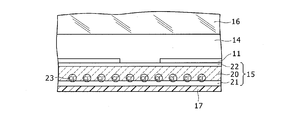
- FIG. 2 is an enlarged view showing a gap portion sandwiched between adjacent solar cells 11 in order to explain the laminated structure of the sealing material 15 on the back surface side.
- the wiring member 13 that connects the adjacent solar cells 11 is disposed in a part of the gap between the adjacent solar cells 11.
- FIG. 2 illustrates the configuration of the sealing member 15. The region where the wiring member 13 is not arranged is shown.
- the first layer 20 is made by adding additives to the main material in various compounding formulations so as to satisfy the heat resistance required for the sealing material 14, the deterioration resistance to sunlight, the translucency, the reflectivity, and the like. Made of materials.
- an inorganic pigment such as titanium oxide or zinc oxide is added as an additive for coloring white.
- Titanium oxide may be added at a mass ratio of about 1 to 5%, preferably 3%.
- the main material of the first layer 20 can be the same material as that of the sealing material 14, but the water content of the first layer 20 is greater than that when no additive is added by further adding an additive. Become more. Moreover, by adding an additive, it contains more impurity ions than when no additive is added.
- titanium oxide has residual Cl since hydrochloric acid may be used in the production process. Further, since titanium oxide is easily decomposed by light, the surface is coated with an inorganic material such as Al 2 O 3 . For this reason, the structure in which titanium oxide is added to the first layer 20 includes impurity ions 23 such as Cl ⁇ , Na + , and Ca + ionized by the presence of water.
- the impurity ions 23 are ions that are introduced into the first layer 20 accompanying the additive material of the first layer 20 and impurities originally contained in a small amount in the main material due to the presence of water.
- Impurity ions 23 include, for example, Ca + , Na + , Cl ⁇ and the like. Some of the impurity ions 23 have a good effect on the characteristics of the solar cell 11, and some have no particular effect on the characteristics, but some have an effect on the deterioration of the characteristics of the solar cell 11.
- Cl ⁇ contributes to the improvement of flame retardancy, but may corrode the transparent conductive film of the photoelectric conversion part of the solar cell 11.
- Cl ⁇ has an effect of reducing the characteristics of the solar cell 11.
- Cl ⁇ will be described as an example of the impurity ions 23 that affect the deterioration of the characteristics of the solar cell 11.
- Cl ⁇ is an example for explanation, and any other impurity ions 23 that affect the deterioration of the characteristics of the solar cell 11 are similarly applied.
- the second layer 21 is a layer provided between the protective member 17 on the back surface side and the first layer 20.
- the second layer 21 is made of a material having a low water content compared to the water content of the first layer 20.
- the third layer 22 is a layer provided between the back surface side of the solar cell 11 and the first layer 20.
- the third layer 22 is made of a material having a low water content compared to the water content of the first layer 20.
- the second layer 21 and the third layer 22 a film made of the same material as the sealing material 14 on the light receiving surface side can be used. Details of the roles of the second layer 21 and the third layer 22 with respect to the first layer 20 will be described below.
- FIG. 3 is a diagram showing the initial water content 24 and the initial impurity ion concentration 25 at the time when the solar cell module 10 is shipped.
- the initial impurity ion concentration 25 is the amount of impurity ions 23 per unit volume.
- Cl ⁇ is representatively shown as one that affects the deterioration of the characteristics of the solar cell 11.
- 3A is a partially enlarged view of FIG. 2, and FIG. 3B is a diagram in which the vertical axis indicates the position in the thickness direction of the sealing material 15 and the horizontal axis indicates the water content and impurity ion concentration. is there.
- the main material of the first layer 20, the second layer 21, and the third layer 22 was a polyethylene olefin resin, and the additive of the first layer 20 was titanium oxide to form a white colored layer.
- the film thickness of the first layer 20 was about 300 to 400 ⁇ m
- the refractive index of the polyethylene-based olefin resin as the main material was about 1.50
- the refractive index of titanium oxide was about 2.5.
- about 3% of titanium oxide was added to the first layer 20.
- the initial water content of the first layer 20 is 300 ppm.
- the impurity ions 23 the first layer 20 contained Cl ⁇ , Na + , Ca + and the like.
- the film thicknesses of the second layer 21 and the third layer 22 were both about 100 ⁇ m. Their initial water content was 90 ppm.
- the water content was measured using a Karl Fischer moisture meter using a coulometric titration method.
- the equipment is ⁇ AQACOUNTER AQ-2100 manufactured by Hiranuma Sangyo Co., Ltd.
- the Karl Fischer coulometric titration method is used. RS-A)]
- the second layer 21 and the third layer 22 composed only of a polyethylene-based olefin resin, and the first layer 20 in which titanium oxide is added to the main material of the polyethylene-based olefin resin
- the initial water content is different.
- the initial moisture content 24 increases in a stepped manner from 90 ppm to 300 ppm between the second layer 21 and the first layer 20, and between the first layer 20 and the third layer 22. Thus, it decreased in a stepped manner from 300 ppm to 90 ppm.
- the impurity ions 23 Cl ⁇ appeared in the first layer 20 containing titanium oxide.
- titanium oxide is uniformly added, and since the initial moisture content 24 is uniform in the first layer 20, the initial impurity ion concentration 25 is along the thickness direction of the first layer 20. The distribution was uniform and zero in the second layer 21 and the third layer 22.
- FIG. 4 is a diagram corresponding to FIG. 3B, in which the horizontal axis indicates the water content and the vertical axis indicates the film thickness (image) of each layer.
- the horizontal axis indicates the water content
- the vertical axis indicates the film thickness (image) of each layer.
- the first layer 20 includes titanium oxide, and titanium oxide can easily contain moisture as compared with a simple polyethylene-based olefin resin. Therefore, the first layer 20 can contain more moisture than the second layer 21 can contain. For this reason, the water content of the first layer 20 is larger than the water content of the second layer 21 at the interface between the second layer 21 and the first layer 20, and the water content increases discontinuously.
- Moisture that has entered the first layer 20 decreases from the interface between the second layer 21 and the first layer 20 toward the interface between the first layer 20 and the third layer 22, and reaches an initial moisture content of 24. Get closer. Therefore, moisture from the protective member 17 hardly penetrates into the third layer 22. Thus, the moisture content 26 when the solar cell module 10 is used under high humidity is along the thickness direction of the first layer 20 at the interface between the second layer 21 and the first layer 20. Shows the highest value.
- the distribution of impurity ion concentration changes. Since the impurity ions are ionized impurities in the presence of water, the impurity ion concentration is high at a high water content, and the impurity ion concentration is low at a low water content. If the amount of impurities in the first layer 20 does not change and the amount of the impurity ions 23 does not change between the initial state and the usage state of the solar cell module 10, the impurities are changed from a low water content to a high water content. It is considered that the ions 23 move.
- the impurity ions 23 move from the side of the third layer 22 having a small in-use water content 26 toward the interface of the second layer 21 having a large in-use water content 26. . Accordingly, the in-use impurity ion concentration 27 becomes the highest value at the interface between the second layer 21 and the first layer 20 along the thickness direction of the first layer 20 and is directed toward the third layer 22 side. The value becomes gradually smaller.
- the impurity ions 23 are removed from the back surface of the solar cell 11. It can be moved to the side of the protective member 17 on the back surface side without facing toward the side.
- the third layer 22 having a water content smaller than the water content of the first layer 20 is arranged on the back surface side of the solar cell 11 with respect to the first layer 20, so that the impurity ions 23 of the solar cell 11 It can further suppress going to the back side. Thereby, impurities contained in the sealing material 15 of the solar cell module 10 can be prevented from affecting the deterioration of the characteristics of the solar cell 11.
Landscapes
- Photovoltaic Devices (AREA)
Description
本発明は、太陽電池モジュールに関する。
太陽電池モジュールでは、太陽電池を封止材によって封止することによって、外部からの衝撃を和らげると共に外部からの水分や汚染物質の浸入を防いでいる。
近年、太陽電池の発電効率を上げるため、太陽電池素子の背面側の封止材として、白色顔料を含ませた白色封止材が用いられることが示されている(特許文献1)。
太陽電池モジュールの封止材に含まれる不純物が太陽電池の特性低下に影響を与えないようにすることである。
本発明に係る太陽電池モジュールは、太陽電池と、太陽電池の裏面側に設けられ、水分を透過する保護部材と、太陽電池の裏面側に設けられ、不純物イオンを含む第1層と、裏面側の保護部材と第1層との間に設けられ、第1層の含水量よりも少ない含水量を有する材料で構成される第2層と、を備え、第1層における不純物イオンが第2層の界面側で多く、太陽電池の裏面側で少ない。
太陽電池の特性低下を抑制する。
以下に図面を用いて、本発明の実施の形態を詳細に説明する。以下で述べる材質、厚さ、寸法等は説明のための例示であって、太陽電池モジュールの仕様に応じ、適宜変更が可能である。以下では、全ての図面において一または対応する要素には同一の符号を付し、重複する説明を省略する。
図1は、太陽電池モジュール10の構造を示す断面図である。太陽電池モジュール10を構成する太陽電池11は、主面として、太陽電池11の外部からの光が主に入射する面である受光面と、受光面と反対側の面である裏面とを有する。図1では、紙面の上側を受光面側、下側を裏面側として示した。
太陽電池モジュール10は、複数の太陽電池11を複数の配線材12,13を用いて互いに直列接続したものを、受光面側の封止材14と裏面側の封止材15で挟み、その外側に受光面側の保護部材16と裏面側の保護部材17を配置し、端部をフレーム18,19で固定して構成される。
太陽電池11は、太陽光等の光を受光することで正孔および電子の光生成キャリアを生成する光電変換部を備える。光電変換部は、例えば、結晶性シリコン(c-Si)、ガリウム砒素(GaAs)、インジウム燐(InP)等の半導体材料の基板を有する。光電変換部の構造は、広義のpn接合である。例えば、n型単結晶シリコン基板と非晶質シリコンのヘテロ接合を用いることができる。この場合、受光面側の基板上に、i型非晶質シリコン層と、ボロン(B)等がドープされたp型非晶質シリコン層と、酸化インジウム(In2O3)の透光性導電酸化物で構成される透明導電膜(TCO)を積層し、基板の裏面側に、i型非晶質シリコン層と、燐(P)等がドープされたn型非晶質シリコン層と、透明導電膜を積層する構造とできる。
光電変換部は、太陽光等の光を電気に変換する機能を有すれば、これ以外の構造であってもよい。例えば、p型多結晶シリコン基板と、その受光面側に形成されたn型拡散層と、その裏面側に形成されたアルミニウム金属膜とを備える構造であってもよい。
配線材12,13は、光電変換部の上の透明導電膜の表面に導電ペースト等を用いて形成された接続用電極に接着剤を介して接続される導電性部材である。配線材12,13としては、銅等の金属導電性材料で構成される薄板が用いられる。薄板に代えて撚り線状のものを用いることもできる。導電性材料としては、銅の他に、銀、アルミニウム、ニッケル、錫、金、あるいはこれらの合金を用いることができる。
接着剤としては、アクリル系、柔軟性の高いポリウレタン系、あるいはエポキシ系等の熱硬化性樹脂接着剤を用いることができる。接着剤には、導電性粒子が含まれる。導電性粒子としては、ニッケル、銀、金コート付ニッケル、錫メッキ付銅等を用いることができる。接着剤として、絶縁性の樹脂接着剤を用いることもできる。この場合には、配線材12,13または接続用電極の互いに対向する面のいずれか一方または双方を凹凸化して、配線材12,13と接続用電極の間から樹脂を適当に排除して電気的接続を取るようにする。
受光面側の封止材14と裏面側の封止材15は、太陽電池11に対し、衝撃の緩衝材としての役割と、汚染物質、異物、水分の侵入を防ぐ機能等を有し、層状に形成される部材である。これらの封止材14,15は、耐熱性、接着性、柔軟性、成形性、耐久性等を考慮して材質が選定される。受光面側の封止材14は、外部からの光を取り入れるため、できるだけ高い透明性を有し、入射した光を吸収したり反射することなく透過させる透明封止材が用いられる。例えば、ポリエチレン系のオレフィン樹脂やエチレンビニルアセテート(EVA)等が用いられる。その他に、EEA、PVB、シリコーン系樹脂、ウレタン系樹脂、アクリル系樹脂、エポキシ系樹脂等を用いることもできる。
裏面側の封止材15は、太陽電池11の裏面と保護部材17の間に配置される。封止材15は、封止材14と同じ材質のものを用いることもできるが、ここでは、中心封止材である第1層20と、第1層20と保護部材17の間に配置される第2層21と、第1層20と太陽電池11との間に配置される第3層22の積層構造が用いられる。
保護部材16には、透光性を有する種々の部材を用いることができるが、耐久性等の観点からガラス基板を用いることが好適である。保護部材17には、コストの削減や軽量化等の観点から、樹脂フィルムを用いることが好適である。樹脂フィルムとしては、オレフィン系樹脂やスチレン系樹脂、ポリエステル系樹脂等からなるフィルムが例示できる。これらのうち、ポリエステル系樹脂フィルムが好ましく、ポリエチレンテレフタレート(PET)フィルムが特に好ましい。PETフィルムは、透光性に優れるため、裏面側からの受光を想定する用途にも好適である。PETフィルム等の樹脂フィルムは、例えば、厚みが50~200μm程度であって、水分を透過する。
図2は、裏面側の封止材15の積層構造を説明するために、隣接する太陽電池11に挟まれた隙間の部分を拡大して示す図である。隣接する太陽電池11で挟まれた隙間の一部の領域には隣接する太陽電池11の間を接続する配線材13が配置されるが、図2では、封止材15の構成を説明するため、配線材13が配置されていない領域を示した。
第1層20は、封止材14に対して要求される耐熱性、太陽光に対する耐劣化性、透光性または反射性等を満たすように、種々の配合処方で添加材を主材料に加えた材料からなる。
例えば、酸化チタンや酸化亜鉛等の無機顔料が白色に着色するための添加材として添加される。酸化チタンは、質量比で約1~5%添加するとよく、好ましくは3%添加することがよい。
第1層20の主材料は、封止材14と同じ材料とすることができるが、さらに添加材が加えられることによって、第1層20の含水量は添加材が加えられていないときに比べ多くなる。また、添加材が加えられることで、添加材が加えられないときに比べ不純物イオンを多く含む。
例えば、酸化チタンは、生成過程で塩酸を用いることがあるので残留Clがある。また、酸化チタンは光によって分解しやすいので、Al2O3等の無機物で表面がコーティングされる。このようなことから、酸化チタンを第1層20に添加する構造の場合、水の存在によってイオン化したCl-,Na+,Ca+等の不純物イオン23が含まれることになる。
不純物イオン23は、第1層20の添加材に付随して第1層20に導入される不純物や、主材料に元々微量含まれる不純物が、水の存在によってイオン化したものである。不純物イオン23は、例えば、Ca+,Na+,Cl-等がある。不純物イオン23の中には太陽電池11の特性に良い影響を与えるもの、特性に特に影響を与えないものもあるが、太陽電池11の特性低下に影響を与えるものもある。
例えば、Cl-は、難燃性の向上に寄与する反面、太陽電池11の光電変換部の透明導電膜を腐食する可能性がある。このように、Cl-は、太陽電池11の特性を低下させる影響を与える。
以下では、太陽電池11の特性低下に影響を与える不純物イオン23の例としてCl-について説明する。ただし、Cl-は説明のための例示であり、これ以外の不純物イオン23であって、太陽電池11の特性低下に影響を与えるものあれば、同様に適用される。
第2層21は、裏面側の保護部材17と第1層20の間に設けられる層である。第2層21は、第1層20の含水量に比べて少ない含水量の材料で構成される。
第3層22は、太陽電池11の裏面側と第1層20の間に設けられる層である。第3層22は、第1層20の含水量に比べて少ない含水量の材料で構成される。
かかる第2層21、第3層22としては、受光面側の封止材14と同じ材料の膜を用いることができる。第1層20に対する第2層21、第3層22の役割の詳細について以下に説明する。
図3は、太陽電池モジュール10の出荷時を初期状態として、そのときの初期含水量24と、初期不純物イオン濃度25を示す図である。初期不純物イオン濃度25は、単位体積当りの不純物イオン23の量である。不純物イオン23としては、太陽電池11の特性低下に影響するものとしてCl-を代表的に示した。図3(a)は、図2の部分拡大図で、(b)は、縦軸に封止材15の厚さ方向の位置を取り、横軸に含水量と不純物イオン濃度を取った図である。
第1層20、第2層21、第3層22の主材料をポリエチレン系オレフィン樹脂とし、第1層20の添加材を酸化チタンとして、白色の着色層とした。第1層20の膜厚は約300~400μm、主材料であるポリエチレン系オレフィン樹脂の屈折率は約1.50で、酸化チタンの屈折率は約2.5であった。また、第1層20には酸化チタンを約3%添加した。このときの第1層20の初期含水量は300ppmである。また、不純物イオン23として、第1層20には、Cl-,Na+,Ca+等が含まれた。第2層21と第3層22の膜厚は、共に約100μmとした。これらの初期含水量は90ppmであった。
含水量の測定には、電量滴定方式によるカールフィッシャー水分計を用いて行った。[装置は平沼産業株式会社社製 AQACOUNTER AQ-2100型式はカールフィッシャー電量滴定方式、測定条件は加熱温度140℃、流量0.25L/min、滴定に用いた試薬はカールフィッシャー試薬(ハイドラナール@アクアライトRS-A)]
図3に示されるように、ポリエチレン系オレフィン樹脂のみで構成される第2層21および第3層22と、ポリエチレン系オレフィン樹脂の主材料に酸化チタンを添加した第1層20とでは、上記のように初期含水量が異なる。図3(b)に示すように、初期含水量24は、第2層21から第1層20の間で、90ppmから300ppmにステップ状に増加し、第1層20から第3層22の間で、300ppmから90ppmにステップ状に低下した。
不純物イオン23であるCl-は、酸化チタンを含む第1層20において現れた。第1層20において、酸化チタンは一様に添加され、また、第1層20において初期含水量24は一様であるので、初期不純物イオン濃度25は、第1層20の厚さ方向に沿って一様な分布となり、第2層21、第3層22ではゼロであった。
このような太陽電池モジュール10が使用されると、外部の湿度の影響を受ける。外部が低湿度であるときは含水量が低下し、水分の低下と共に不純物イオン23も少なくなるので、あまり大きな問題とならない。そこで、以下では、外部が高湿度である場合の含水量と不純物イオン濃度の変化について、図4、図5を用いて考察する。
外部が高湿度であると、外部からの水分は裏面側の保護部材17を通して、裏面側の保護部材17側から太陽電池11の側に浸透する。その様子を図4に示す。図4は、図3(b)に対応する図であるが、横軸に含水量、縦軸に各層の膜厚(イメージ)を示す。外部からの水分が保護部材17を通して第2層21に入ると、第2層21の含水量が増加する。図4では、第2層21において、保護部材17の側に高く、第1層20との界面側に低い含水量分布が示される。
保護部材17からの水分が第2層21を透過して第1層20に入ると、第1層20の含水量が増加する。第1層20は酸化チタンを含み、酸化チタンは単なるポリエチレン系オレフィン樹脂に比べて水分を含有しやすいので、第2層21が含有できる水分よりも多くの水分を含有できる。このことから、第2層21と第1層20との間の界面では第2層21の含水量よりも第1層20の含水量が多く、含水量が不連続的に増加する。
第1層20に入った水分は、第2層21と第1層20との間の界面から第1層20と第3層22との間の界面に向かって減少し、初期含水量24に近づく。したがって、保護部材17からの水分は第3層22にはほとんど浸透しない。このように、太陽電池モジュール10の高湿度下の使用状態における使用時含水量26は、第1層20の厚さ方向に沿って、第2層21と第1層20との間の界面で最も高い値を示す。
太陽電池モジュール10が高湿度下の使用状態に置かれて、第1層20の含水量分布が均一分布から図4に示すように変化すると、不純物イオン濃度の分布が変化する。不純物イオンは、水の存在で不純物がイオン化したものであるので、含水量の多いところの不純物イオン濃度が高くなり、含水量の少ないところの不純物イオン濃度が低くなる。太陽電池モジュール10の初期状態と使用状態の間で、第1層20における不純物の量が変わらず、不純物イオン23の量も変わらないとすると、含水量の少ないところから含水量の多いところに不純物イオン23が移動すると考えられる。
このことから、第1層20において、使用時含水量26の少ない第3層22の側から、使用時含水量26の多い第2層21の界面に向かって、不純物イオン23が移動すると考えられる。したがって、使用時不純物イオン濃度27は、第1層20の厚さ方向に沿って、第2層21と第1層20との間の界面で最も高い値となり、第3層22の側に向かって次第に小さい値となる。
このように、第1層20よりも裏面側の保護部材17の側に第1層20の含水量より少ない含水量の第2層21を配置することで、不純物イオン23を太陽電池11の裏面側に向かわせず、裏面側の保護部材17の側に移動させることができる。また、必要に応じて、第1層20よりも太陽電池11の裏面側に第1層20の含水量より少ない含水量の第3層22を配置することで、不純物イオン23が太陽電池11の裏面側に向かうことをさらに抑制することができる。これによって、太陽電池モジュール10の封止材15に含まれる不純物が太陽電池11の特性低下に影響を与えないようにできる。
10 太陽電池モジュール、11 太陽電池、12,13 配線材、14,15 封止材、16,17 保護部材、18,19 フレーム、20 第1層、21 第2層、22 第3層、23 不純物イオン、24 初期含水量、25 初期不純物イオン濃度、26 使用時含水量、27 使用時不純物イオン濃度。
Claims (3)
- 太陽電池と、
前記太陽電池の裏面側に設けられ、水分を透過する保護部材と、
前記太陽電池の裏面側に設けられ、不純物イオンを含む第1層と、
前記保護部材と前記第1層との間に設けられ、前記第1層の含水量よりも少ない含水量を有する材料で構成される第2層と、
を備え、
前記第1層における不純物イオンが前記第2層の界面側で多く、太陽電池の裏面側で少ない、太陽電池モジュール。 - 請求項1に記載の太陽電池モジュールにおいて、
前記第1層に含まれるイオン化した不純物は、塩素イオンである、太陽電池モジュール。 - 請求項1に記載の太陽電池モジュールにおいて、
前記第1層の含水量よりも少ない含水量の材料で構成される第3層が前記太陽電池の裏面側と前記第1層との間に設けられる、太陽電池モジュール。
Priority Applications (2)
| Application Number | Priority Date | Filing Date | Title |
|---|---|---|---|
| PCT/JP2012/072206 WO2014033924A1 (ja) | 2012-08-31 | 2012-08-31 | 太陽電池モジュール |
| JP2014532690A JPWO2014033924A1 (ja) | 2012-08-31 | 2012-08-31 | 太陽電池モジュール |
Applications Claiming Priority (1)
| Application Number | Priority Date | Filing Date | Title |
|---|---|---|---|
| PCT/JP2012/072206 WO2014033924A1 (ja) | 2012-08-31 | 2012-08-31 | 太陽電池モジュール |
Publications (1)
| Publication Number | Publication Date |
|---|---|
| WO2014033924A1 true WO2014033924A1 (ja) | 2014-03-06 |
Family
ID=50182770
Family Applications (1)
| Application Number | Title | Priority Date | Filing Date |
|---|---|---|---|
| PCT/JP2012/072206 Ceased WO2014033924A1 (ja) | 2012-08-31 | 2012-08-31 | 太陽電池モジュール |
Country Status (2)
| Country | Link |
|---|---|
| JP (1) | JPWO2014033924A1 (ja) |
| WO (1) | WO2014033924A1 (ja) |
Citations (5)
| Publication number | Priority date | Publication date | Assignee | Title |
|---|---|---|---|---|
| JP2003243679A (ja) * | 2002-02-18 | 2003-08-29 | Dainippon Printing Co Ltd | 太陽電池モジュ−ル用裏面保護シ−トおよびそれを使用した太陽電池モジュ−ル |
| JP2012104612A (ja) * | 2010-11-09 | 2012-05-31 | Fujifilm Corp | 太陽電池保護シート及びその製造方法、太陽電池用バックシート、並びに太陽電池モジュール |
| JP2012106488A (ja) * | 2010-10-25 | 2012-06-07 | Techno Polymer Co Ltd | 積層シート及びそれを備える太陽電池モジュール |
| JP2012109294A (ja) * | 2010-11-15 | 2012-06-07 | Toppan Printing Co Ltd | 太陽電池用裏面保護シート及びこれを用いた太陽電池 |
| JP2012148557A (ja) * | 2010-12-27 | 2012-08-09 | Mitsubishi Plastics Inc | 太陽電池保護用積層体及びそれを用いて作製された太陽電池モジュール |
-
2012
- 2012-08-31 JP JP2014532690A patent/JPWO2014033924A1/ja active Pending
- 2012-08-31 WO PCT/JP2012/072206 patent/WO2014033924A1/ja not_active Ceased
Patent Citations (5)
| Publication number | Priority date | Publication date | Assignee | Title |
|---|---|---|---|---|
| JP2003243679A (ja) * | 2002-02-18 | 2003-08-29 | Dainippon Printing Co Ltd | 太陽電池モジュ−ル用裏面保護シ−トおよびそれを使用した太陽電池モジュ−ル |
| JP2012106488A (ja) * | 2010-10-25 | 2012-06-07 | Techno Polymer Co Ltd | 積層シート及びそれを備える太陽電池モジュール |
| JP2012104612A (ja) * | 2010-11-09 | 2012-05-31 | Fujifilm Corp | 太陽電池保護シート及びその製造方法、太陽電池用バックシート、並びに太陽電池モジュール |
| JP2012109294A (ja) * | 2010-11-15 | 2012-06-07 | Toppan Printing Co Ltd | 太陽電池用裏面保護シート及びこれを用いた太陽電池 |
| JP2012148557A (ja) * | 2010-12-27 | 2012-08-09 | Mitsubishi Plastics Inc | 太陽電池保護用積層体及びそれを用いて作製された太陽電池モジュール |
Also Published As
| Publication number | Publication date |
|---|---|
| JPWO2014033924A1 (ja) | 2016-08-08 |
Similar Documents
| Publication | Publication Date | Title |
|---|---|---|
| JP5842170B2 (ja) | 太陽電池モジュール | |
| US9337357B2 (en) | Bifacial solar cell module | |
| JP5999571B2 (ja) | 太陽電池モジュール | |
| JPWO2020054130A1 (ja) | 太陽電池モジュール | |
| US20150214410A1 (en) | Solar cell module | |
| KR20160116745A (ko) | 정션 박스 및 이를 포함하는 태양 전지 모듈 | |
| CN104205619B (zh) | 太阳能电池装置 | |
| KR20120051972A (ko) | 태양 전지 모듈 | |
| KR101814821B1 (ko) | 태양전지 모듈 | |
| KR20220166520A (ko) | 태양광 모듈 및 이의 제조 방법 | |
| JP2018037481A (ja) | 太陽電池モジュールおよび太陽電池モジュールの製造方法 | |
| US20130037084A1 (en) | Photovoltaic Module Light Manipulation for Increased Module Output | |
| WO2016084299A1 (ja) | 太陽電池セル及び太陽電池モジュール | |
| JP6621029B2 (ja) | 太陽電池モジュール | |
| JP2016143680A (ja) | 太陽電池モジュール | |
| JPWO2014033924A1 (ja) | 太陽電池モジュール | |
| KR101685350B1 (ko) | 태양 전지 모듈 | |
| KR101470065B1 (ko) | 태양전지 모듈 | |
| KR101382739B1 (ko) | 태양전지 모듈 및 이의 제조 방법 | |
| KR101349495B1 (ko) | 태양전지 모듈 및 이의 제조방법 | |
| KR101283159B1 (ko) | 태양광 발전장치 및 이의 제조방법 | |
| WO2023127382A1 (ja) | 太陽電池デバイスおよび太陽電池モジュール | |
| KR20230135819A (ko) | 태양광 모듈 | |
| KR20230036768A (ko) | 일반 전극 패턴이 형성된 태양전지를 이용한 양면수광형 슁글드 모듈 및 그 제조 방법 | |
| KR20170056236A (ko) | 메탈 웰딩 태양전지 |
Legal Events
| Date | Code | Title | Description |
|---|---|---|---|
| 121 | Ep: the epo has been informed by wipo that ep was designated in this application |
Ref document number: 12883866 Country of ref document: EP Kind code of ref document: A1 |
|
| ENP | Entry into the national phase |
Ref document number: 2014532690 Country of ref document: JP Kind code of ref document: A |
|
| NENP | Non-entry into the national phase |
Ref country code: DE |
|
| 122 | Ep: pct application non-entry in european phase |
Ref document number: 12883866 Country of ref document: EP Kind code of ref document: A1 |