WO2014033895A1 - ホログラム記録装置及びホログラム記録方法 - Google Patents
ホログラム記録装置及びホログラム記録方法 Download PDFInfo
- Publication number
- WO2014033895A1 WO2014033895A1 PCT/JP2012/072099 JP2012072099W WO2014033895A1 WO 2014033895 A1 WO2014033895 A1 WO 2014033895A1 JP 2012072099 W JP2012072099 W JP 2012072099W WO 2014033895 A1 WO2014033895 A1 WO 2014033895A1
- Authority
- WO
- WIPO (PCT)
- Prior art keywords
- area
- recording
- hologram recording
- post
- cure
- Prior art date
- Legal status (The legal status is an assumption and is not a legal conclusion. Google has not performed a legal analysis and makes no representation as to the accuracy of the status listed.)
- Ceased
Links
Images









Classifications
-
- G—PHYSICS
- G11—INFORMATION STORAGE
- G11B—INFORMATION STORAGE BASED ON RELATIVE MOVEMENT BETWEEN RECORD CARRIER AND TRANSDUCER
- G11B7/00—Recording or reproducing by optical means, e.g. recording using a thermal beam of optical radiation by modifying optical properties or the physical structure, reproducing using an optical beam at lower power by sensing optical properties; Record carriers therefor
- G11B7/004—Recording, reproducing or erasing methods; Read, write or erase circuits therefor
- G11B7/0065—Recording, reproducing or erasing by using optical interference patterns, e.g. holograms
-
- G—PHYSICS
- G03—PHOTOGRAPHY; CINEMATOGRAPHY; ANALOGOUS TECHNIQUES USING WAVES OTHER THAN OPTICAL WAVES; ELECTROGRAPHY; HOLOGRAPHY
- G03H—HOLOGRAPHIC PROCESSES OR APPARATUS
- G03H1/00—Holographic processes or apparatus using light, infrared or ultraviolet waves for obtaining holograms or for obtaining an image from them; Details peculiar thereto
- G03H1/04—Processes or apparatus for producing holograms
- G03H1/18—Particular processing of hologram record carriers, e.g. for obtaining blazed holograms
- G03H1/182—Post-exposure processing, e.g. latensification
-
- G—PHYSICS
- G03—PHOTOGRAPHY; CINEMATOGRAPHY; ANALOGOUS TECHNIQUES USING WAVES OTHER THAN OPTICAL WAVES; ELECTROGRAPHY; HOLOGRAPHY
- G03H—HOLOGRAPHIC PROCESSES OR APPARATUS
- G03H1/00—Holographic processes or apparatus using light, infrared or ultraviolet waves for obtaining holograms or for obtaining an image from them; Details peculiar thereto
- G03H1/04—Processes or apparatus for producing holograms
- G03H1/18—Particular processing of hologram record carriers, e.g. for obtaining blazed holograms
- G03H2001/185—Applying a curing step
-
- G—PHYSICS
- G11—INFORMATION STORAGE
- G11B—INFORMATION STORAGE BASED ON RELATIVE MOVEMENT BETWEEN RECORD CARRIER AND TRANSDUCER
- G11B7/00—Recording or reproducing by optical means, e.g. recording using a thermal beam of optical radiation by modifying optical properties or the physical structure, reproducing using an optical beam at lower power by sensing optical properties; Record carriers therefor
- G11B2007/0003—Recording, reproducing or erasing systems characterised by the structure or type of the carrier
- G11B2007/0009—Recording, reproducing or erasing systems characterised by the structure or type of the carrier for carriers having data stored in three dimensions, e.g. volume storage
-
- G—PHYSICS
- G11—INFORMATION STORAGE
- G11B—INFORMATION STORAGE BASED ON RELATIVE MOVEMENT BETWEEN RECORD CARRIER AND TRANSDUCER
- G11B20/00—Signal processing not specific to the method of recording or reproducing; Circuits therefor
- G11B20/10—Digital recording or reproducing
- G11B20/12—Formatting, e.g. arrangement of data block or words on the record carriers
- G11B2020/1264—Formatting, e.g. arrangement of data block or words on the record carriers wherein the formatting concerns a specific kind of data
- G11B2020/1288—Formatting by padding empty spaces with dummy data, e.g. writing zeroes or random data when de-icing optical discs
Definitions
- the present invention relates to a recording apparatus and a recording method using holography.
- the Blu-ray Disc (TM) standard using a blue-violet semiconductor laser has made it possible to commercialize an optical disc having a recording capacity of about 50 GB even for consumer use.
- HDD Hard Disk Drive
- Hologram recording technology is a method in which signal light having page data information two-dimensionally modulated by a spatial light modulator is superimposed on reference light inside the recording medium, and the interference fringe pattern generated at that time is placed in the recording medium. This is a technique for recording information on a recording medium by causing refractive index modulation.
- the hologram recorded in the recording medium acts like a diffraction grating to generate diffracted light. This diffracted light is reproduced as the same light including the recorded signal light and phase information.
- Regenerated signal light is detected two-dimensionally at high speed using a photodetector such as a CMOS or CCD.
- a photodetector such as a CMOS or CCD.
- the hologram recording technique enables two-dimensional information to be recorded on the optical recording medium at once by one hologram and further reproduces this information. Since the page data can be overwritten, large-capacity and high-speed information recording / reproduction can be achieved.
- FIG. 5 is a graph showing a time response characteristic of diffraction efficiency with respect to a waiting time from the end of recording to post-processing (time to post-processing) in a typical hologram recording medium using a photopolymer. As shown here, if the time until post-processing is short, sufficient diffraction efficiency cannot be obtained.Therefore, from the diffusion rate of the monomer detected as the state of the hologram recording medium, sufficient diffusion is sufficient. It is possible to determine the time required for performing a proper refractive index modulation as an ideal time until post-processing. "
- Patent Document 2 also states that “the holographic medium is fixed at the same time as a data recording event that is performed in a different area of the holographic medium, not in the fixed area”. “The transmitted portion of the reference beam is re-guided by the optical system 107 to the portion of the photosensitive medium that needs to be fixed. The advantage of incorporating the optical system 107 is that the region 35 to be fixed by the reference beam It is not necessary to be adjacent to the area 34 to be recorded at the same time.
- An object of the present invention is to provide a hologram recording apparatus and a hologram recording method for realizing suitable recording on a hologram recording medium.
- FIG. 1 is a block diagram showing a hologram recording / reproducing apparatus of Example 1.
- FIG. It is a figure explaining the recording principle of a hologram recording / reproducing apparatus. It is a figure explaining the reproduction
- 3 is a processing flow of data recording processing in Embodiment 1.
- FIG. 3 is a diagram illustrating the arrangement of pre-post cure areas in the first embodiment.
- FIG. 6 is a block diagram showing a hologram recording / reproducing apparatus of Example 2. It is a figure which shows the relationship between the pre-cure area
- region. It is a figure which shows the relationship between the book case in Example 2, and a book. 10 is a processing flow of data recording processing in Embodiment 2. It is a figure for demonstrating the effect of Example 2.
- FIG. 6 is a block diagram showing a hologram recording / reproducing apparatus of Example 2. It is a figure which shows the relationship between the pre-cure area
- region. It is a figure which shows the relationship between the book case in Example 2, and a book. 10 is a processing flow of data recording processing in Embodiment 2. It is a figure for demonstrating the effect of Example 2.
- FIG. It is a figure for demonstrating the effect of Example 2.
- FIG. It is a figure for demonstrating the modification of this invention. It is a figure for demonstrating the modification of this invention. It is a data processing flow at the time of recording. It is a data processing flow at the time of reproduction. It is a block diagram of the signal generation circuit in a hologram recording / reproducing apparatus. It is a block diagram of the signal processing circuit in a hologram recording / reproducing apparatus.
- FIG. 1 is a block diagram showing a recording / reproducing apparatus for a hologram recording medium for recording and / or reproducing digital information using holography.
- the hologram recording / reproducing device 10 is connected to an external control device 91 via an input / output control circuit 90.
- the hologram recording / reproducing apparatus 10 receives an information signal to be recorded from the external control device 91 by the input / output control circuit 90.
- the hologram recording / reproducing apparatus 10 transmits the reproduced information signal to the external control apparatus 91 by the input / output control circuit 90.
- the hologram recording / reproducing apparatus 10 includes a pickup 11, a reproducing reference light optical system 12, a cure optical system 13, and a medium transport unit 50.
- the hologram recording medium 1 is transferred to a predetermined plane (the hologram recording medium 1 by the medium transport unit 50).
- the plane can be translated along a plane parallel to the surface.
- the medium transport unit 50 can be realized by, for example, a two-axis movable stage of X-axis and Y-axis, and can be used for the purpose of changing the recording position of the hologram recording medium 1, for example.
- the recording position on the hologram recording medium 1 can be controlled by driving the medium transport unit 50 via the medium transport control circuit 81 by the controller 89. That is, the medium conveyance control circuit 81 and the medium conveyance unit 50 according to the present embodiment function as means for changing the recording position on the hologram recording medium 1.
- the pickup 11 plays a role of irradiating the hologram recording medium 1 with reference light and signal light and recording digital information on the recording medium using holography.
- an information signal to be recorded is sent by a controller 89 to a spatial light modulator (to be described later) in the pickup 11 via a signal generation circuit 86, and the signal light is modulated by the spatial light modulator.
- the reproduction reference light optical system 12 When reproducing the information recorded on the hologram recording medium 1, the reproduction reference light optical system 12 generates a light wave that causes the reference light emitted from the pickup 11 to enter the hologram recording medium 1 in the direction opposite to that during recording. To do. Reproduction light reproduced by the reproduction reference light is detected by a photodetector (to be described later) in the pickup 11, and a signal is reproduced by the signal processing circuit 85.
- the irradiation time of the reference light and the signal light applied to the hologram recording medium 1 can be adjusted by controlling the opening / closing time of the shutter in the pickup 11 by the controller 89 via the shutter control circuit 87.
- the cure optical system 13 plays a role of generating a light beam used for pre-cure and post-cure of the hologram recording medium 1.
- Pre-curing is a pre-process for irradiating a predetermined light beam in advance before irradiating the reference light and signal light to the desired position when recording information at the desired position in the hologram recording medium 1.
- Post-cure is a post-process for irradiating a predetermined light beam after recording information at a desired position in the hologram recording medium 1 so that additional recording cannot be performed at the desired position.
- the light beam used for pre-cure and post-cure is preferably incoherent light, that is, light with low coherence.
- a predetermined light source driving current is supplied from the light source driving circuit 82 to the light sources in the pickup 11 and the cure optical system 13, and each light source can emit a light beam with a predetermined light quantity.
- the recording technology using the principle of angle multiplexing of holography tends to have a very small tolerance for the deviation of the reference beam angle.
- a mechanism for detecting the deviation amount of the reference beam angle is provided in the pickup 11, a servo control signal is generated by the servo signal generation circuit 83, and the deviation amount is corrected via the servo control circuit 84. It is necessary to provide a servo mechanism for this in the hologram recording / reproducing apparatus 10.
- the pickup 11 and the cure optical system 13 may be simplified by combining several optical system configurations or all optical system configurations into one.
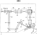
- FIG. 2 shows a recording principle in an example of a basic optical system configuration of the pickup 11 and the reproducing reference light optical system 12 in the hologram recording / reproducing apparatus 10.
- the reproduction reference light optical system 12 includes an actuator 223 and a galvanometer mirror 224.
- the light beam emitted from the light source 201 passes through the collimator lens 202 and enters the shutter 203.
- the optical element 204 composed of, for example, a half-wave plate or the like, adjusts the light quantity ratio of p-polarized light and s-polarized light to a desired ratio.
- the light beam enters a PBS (Polarization Beam Splitter) prism 205.
- the light beam that has passed through the PBS prism 205 functions as signal light 206, and after the light beam diameter is expanded by the beam expander 208, the light beam passes through the phase mask 209, the relay lens 210, and the PBS prism 211 and passes through the spatial light modulator 212. Is incident on.
- the signal light to which information is added by the spatial light modulator 212 reflects the PBS prism 211 and propagates through the relay lens 213 and the spatial filter 214. Thereafter, the signal light is condensed on the hologram recording medium 1 by the objective lens 215.
- the light beam reflected by the PBS prism 205 works as reference light 207, and is set to a predetermined polarization direction according to recording or reproduction by the polarization direction conversion element 216, and then galvanically passed through the mirror 217 and the mirror 218. Incident on the mirror 219. Since the angle of the galvanometer mirror 219 can be adjusted by the actuator 220, the incident angle of the reference light incident on the hologram recording medium 1 after passing through the lens 221 and the lens 222 can be set to a desired angle. In order to set the incident angle of the reference light, an element that converts the wavefront of the reference light may be used instead of the galvanometer mirror.
- the signal light and the reference light are incident on the hologram recording medium 1 so as to overlap each other, whereby an interference fringe pattern is formed in the recording medium, and information is recorded by writing this pattern on the recording medium.
- the incident angle of the reference light incident on the hologram recording medium 1 can be changed by the galvanometer mirror 219, recording by angle multiplexing is possible.
- holograms corresponding to each reference beam angle are called pages, and a set of pages angle-multiplexed in the same area is called a book. .
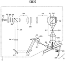
- FIG. 3 shows a reproduction principle in an example of a basic optical system configuration of the pickup 11 and the reproduction reference light optical system 12 in the hologram recording / reproduction apparatus 10.
- the reference beam is incident on the hologram recording medium 1 as described above, and the light beam transmitted through the hologram recording medium 1 is reflected by the galvanometer mirror 224 whose angle can be adjusted by the actuator 223.
- the reference light for reproduction is generated.
- the reproduction light reproduced by the reproduction reference light propagates through the objective lens 215, the relay lens 213, and the spatial filter 214. Thereafter, the reproduction light passes through the PBS prism 211 and enters the photodetector 225, and the recorded signal can be reproduced.
- the photodetector 225 for example, an image sensor such as a CMOS image sensor or a CCD image sensor can be used, but any element may be used as long as page data can be reproduced.
- FIG. 4 shows a recording / reproducing operation flow in the hologram recording / reproducing apparatus 10.
- a flow relating to recording / reproduction using holography in particular will be described.
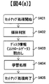
- a process from when the hologram recording medium 1 is inserted into the hologram recording / reproducing apparatus 10 until preparation for recording or reproduction is completed is referred to as a setup process.
- the process of recording information on the hologram recording medium 1 from the ready state is called a recording process
- the process of reproducing information recorded on the hologram recording medium 1 from the ready state is called a playback process.
- FIG. 4A shows the operation flow of the setup process
- FIG. 4B shows the operation flow of the recording process
- FIG. 4C shows the operation flow of the reproduction process.
- the hologram recording / reproducing apparatus 10 determines whether the inserted medium is a medium for recording or reproducing digital information using holography, for example.
- the medium is determined (step S402).
- the hologram recording / reproducing apparatus 10 reads control data provided on the hologram recording medium 1 (step S403). ), For example, information relating to the hologram recording medium 1 and information relating to various setting conditions during recording and reproduction, for example.
- step S404 After reading the control data, various adjustments according to the control data and learning processing related to the pickup 11 (step S404) are performed. Thereby, the hologram recording / reproducing apparatus 10 completes preparation for recording or reproduction, and ends the setup process (step S405).
- the hologram recording / reproducing apparatus 10 receives the recording data (step S412), and sends two-dimensional data corresponding to the data to the spatial light modulator 212 in the pickup 11.
- various recording learning processes such as optimization of the power of the light source 201 and optimization of exposure time by the shutter 203 are performed in advance so that high-quality information can be recorded on the hologram recording medium 1 (steps). S413).
- the medium transport unit 50 is controlled via the medium transport control circuit 81, and the light beam irradiated from the pickup 11 and the cure optical system 13 is irradiated to a predetermined position of the hologram recording medium 1.
- the hologram recording medium 1 is positioned.
- the hologram recording medium 1 has address information, it reproduces the address information, confirms whether it is positioned at the target position, and calculates the amount of deviation from the predetermined position if it is not positioned at the target position. The operation of positioning again is repeated.
- step S415 a data recording process for recording data to be recorded as a hologram on the hologram recording medium 1 is performed. Details of the data recording process will be described later.
- the recording process is terminated (step S416). Note that data may be verified as necessary.
- the hologram recording / reproducing apparatus 10 first controls the medium conveyance control circuit 81 in the seek operation (step S422), and the light emitted from the pickup 11 and the reproduction reference light optical system 12 is irradiated.
- the hologram recording medium 1 is positioned so that the beam is irradiated to a predetermined position of the hologram recording medium 1.
- the hologram recording medium 1 has address information, it reproduces the address information, confirms whether it is positioned at the target position, and calculates the amount of deviation from the predetermined position if it is not positioned at the target position. The operation of positioning again is repeated.
- step S423 information recorded on the hologram recording medium 1 is read from the two-dimensional data detected by the photodetector 225 (step S423), and reproduction data is transmitted (step S424).
- reproduction data is transmitted (step S425).
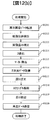
- FIG. 12 shows a data processing flow during recording and reproduction.
- FIG. 12A shows the two-dimensional data on the spatial light modulator 212 after the recording data receiving process S412 in the input / output control circuit 90.
- FIG. 12B shows a recording data processing flow in the signal generation circuit 86 until conversion.
- FIG. 12B shows the process up to reproduction data transmission processing S424 in the input / output control circuit 90 after the two-dimensional data is detected by the photodetector 225.
- the reproduction data processing flow in the signal processing circuit 85 is shown.
- step S1201 When recording data is received (step S1201), it is divided into a plurality of data strings, and each data string is converted to CRC (step S1202) so that an error can be detected during reproduction. After performing scramble (step S1203) to add a pseudo-random data sequence to the data sequence for the purpose of preventing pattern repetition, error correction coding such as Reed-Solomon code (step S1204) so that error correction can be performed during reproduction. I do.
- this data string is converted into two-dimensional data of M ⁇ N, and two-dimensional data for one page (step S1205) is configured by repeating the data for one page of data.
- a marker serving as a reference for image position detection and image distortion correction during reproduction is added to the two-dimensional data configured as described above (step S1206), and the data is transferred to the spatial light modulator 212 (step S1207).
- Image data detected by the photodetector 225 is transferred to the signal processing circuit 85 (step S1211).
- An image position is detected based on a marker included in the image data (step S1212), and distortion such as inclination, magnification, and distortion of the image is corrected (step S1213), and then binarization processing (step S1214) is performed.
- step S1215 By removing the marker (step S1215), two-dimensional data for one page is acquired (step S1216).
- error correction processing step S1217) is performed to remove the parity data strings.
- descrambling processing step S1218) is performed, CRC error detection processing (step S1219) is performed and CRC parity is deleted, and then reproduction data is transmitted via the input / output control circuit 90 (step S1220).
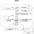
- FIG. 13 is a block diagram of the signal generation circuit 86 of the hologram recording / reproducing apparatus 10.
- the input / output control circuit 90 When input of recording data is started to the input / output control circuit 90, the input / output control circuit 90 notifies the controller 89 that input of recording data has started. In response to this notification, the controller 89 instructs the signal generation circuit 86 to record data for one page input from the input / output control circuit 90. A processing command from the controller 89 is notified to the sub-controller 8601 in the signal generation circuit 86 via the control line 8608. Upon receiving this notification, the sub-controller 8601 controls each signal processing circuit via the control line 8608 so that the signal processing circuits are operated in parallel. First, the memory control circuit 8603 is controlled to store the recording data input from the input / output control circuit 90 via the data line 8609 in the memory 8602.
- the CRC calculation circuit 8604 performs control to convert the recording data into CRC.
- the CRC-converted data is scrambled by adding a pseudo-random data sequence by the scramble circuit 8605, and the error correction encoding circuit 8606 performs error correction encoding by adding the parity data sequence.
- the pickup interface circuit 8607 reads out the error correction encoded data from the memory 8602 in the order of the two-dimensional data on the spatial light modulator 212, adds a reference marker at the time of reproduction, Two-dimensional data is transferred to the spatial light modulator 212.
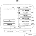
- FIG. 14 is a block diagram of the signal processing circuit 85 of the hologram recording / reproducing apparatus 10.
- the controller 89 instructs the signal processing circuit 85 to reproduce the data for one page input from the pickup 11.
- a processing command from the controller 89 is notified to the sub-controller 8501 in the signal processing circuit 85 via the control line 8511.
- the sub-controller 8501 controls each signal processing circuit via the control line 8511 so that the signal processing circuits are operated in parallel.
- the memory control circuit 8503 is controlled to store image data input from the pickup 11 via the pickup interface circuit 8510 via the data line 8512 in the memory 8502.
- the image position detection circuit 8509 performs control to detect a marker from the image data stored in the memory 8502 and extract an effective data range.
- the image distortion correction circuit 8508 performs distortion correction such as image inclination, magnification, and distortion by using the detected marker, and controls to convert the image data into the expected two-dimensional data size.
- Each bit data of a plurality of bits constituting the size-converted two-dimensional data is binarized by determining “0” and “1” in the binarization circuit 8507, and the data is arranged in the memory 8502 in the order of the output of the reproduction data Control to store.
- the error correction circuit 8506 corrects an error included in each data string, and the scramble release circuit 8505 releases the scramble to add the pseudo random number data string, and then the CRC calculation circuit 8504 causes an error in the reproduction data on the memory 8502. Check not included. Thereafter, the reproduction data is transferred from the memory 8502 to the input / output control circuit 90.
- step S502 the hologram recording / reproducing apparatus 10 pre-cures a predetermined area using the light beam emitted from the cure optical system 13 (step S503).
- the area pre-cured in step S503 is hereinafter referred to as a pre-cured area.
- step S503 hologram recording is performed using signal light and reference light.
- angle multiplexing is performed by changing the angle of the reference beam, and multiplex recording is performed on the same volume.
- a unit called a book an area in which only the angle of the reference beam is changed and multiple recording is performed on the same volume of the hologram recording medium 1 is referred to as a unit called a book. That is, after step S503, multiple recording is performed for one book (step S504).
- pre-cure area to be pre-cured in step S503 is larger than the size of one book.
- a unit used to spread a book is referred to as a book case in this specification. Furthermore, in this embodiment, it is assumed that the pre-cure area and the book case are the same. That is, the pre-cure area pre-cured in step S503 is divided into areas of a predetermined size called books, and recording is performed for each book.
- step S505 it is determined whether or not recording of all books is completed for the book case currently being recorded (in this embodiment, the same as the pre-cure area where the pre-cure was performed in step S503) (step S505).
- step S506 If the recording of all books is not completed for the book case currently being recorded (No in step S505), the book is moved (step S506). This process is performed by moving the hologram recording medium 1 by the medium transport unit 50, and is positioned at an unrecorded position inside the book case currently being recorded. After step S506, the process returns to step S504, and the book is recorded at the position positioned in step S506.
- the pre-cure area where the pre-cure is performed in step S503 is in a state of being laid out with recorded books. That is, according to the above operation, the recording process is performed so that the hologram is recorded at a predetermined interval inside the predetermined area (bookcase) on the hologram recording medium.
- bookcase record A series of recordings in which a hologram is recorded while changing the recording position so that the hologram in which information is recorded is arranged at a predetermined interval inside a predetermined area called a book case is called book case recording. Called. Bookcase recording can be rephrased as an operation of laying down while recording a book in a predetermined area called a bookcase.
- bookcase recording is performed according to an instruction from the controller 89.
- the medium conveyance unit 50 is driven through the medium conveyance control circuit 81 to change the recording position, and the irradiation time of the reference light and the signal light is controlled through the shutter control circuit 87.
- the bookcase recording is performed. That is, in this embodiment, the controller 89 functions as a means for performing bookcase recording.
- step S505 the variable k is counted up (step S507), and it is determined whether the variable k is equal to or greater than a predetermined numerical value N (step S508).
- the predetermined numerical value N is an integer of 2 or more.
- step S509 If the variable k is not greater than or equal to the predetermined numerical value N (No in step S508), the process moves to the next bookcase (step S509). This process is realized by changing the positions of the pickup 11 and the cure optical system 13 relatively by changing the position of the hologram recording medium 1 by controlling the medium conveyance control circuit 81. After step S509, the process returns to step S503. By this operation, the book case recording is similarly performed for the next book case.
- step S510 When the variable k is greater than or equal to the predetermined numerical value N (Yes in step S508), post-cure is performed using the light beam emitted from the cure optical system 13 for the recorded and post-cure unexecuted region (step S510). . After the counter reset in step S502, this condition is satisfied when all of the N bookcases are spread with recorded books, and postcuring is performed on the N bookcases in step S510.
- the area post-cured in step S510 is hereinafter referred to as a post-cure area. The order in which N bookcases are post-cured will be described later.
- step S510 it is determined whether recording has been completed for the entire surface of the hologram recording medium 1 (step S511). If recording has not been completed on the entire surface of the hologram recording medium 1 (No in step S511), the medium transport unit 50 is driven to change the position of the hologram recording medium 1 and move to the next bookcase (step). S512). After step S512, the process returns to step S502.
- variable k When returning to step S502 after step S512, the variable k is reset. With the above operation, the variable k becomes a variable for counting the number of bookcases that have not been post-cured and are spread with recorded books.
- step S513 When recording is completed for the entire surface of the hologram recording medium 1 (Yes in step S511), the data recording process is terminated (step S513).
- post-cure is not performed immediately after the book case recording for the book case is completed.
- Perform a series of operations N times
- Precure for each bookcase and record the bookcase for that bookcase in other words, lay down the bookcase while recording the book
- Post-cure all N book cases This operation is repeated until recording is completed for the entire surface of the hologram recording medium 1.
- FIG. 6 is a diagram showing the relationship between the pre-cure area and the book case, book, and post-cure area in the present embodiment.
- reference numerals 601, 602, and 603 denote book cases, which are the same as the pre-cure area in this embodiment.
- the book case has a rectangular shape. It is assumed that bookcase recording is performed for a total of N bookcases in the order of reference numeral 601, reference numeral 602,.
- Reference numeral 604 denotes a post-cure area, which is a set of the N book cases described above.
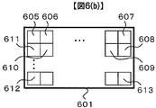
- FIG. 6B illustrates a single book case
- FIG. 6B illustrates the first book case 601 as an example.
- Reference numerals 605 to 613 each denote a book
- the books are arranged in the first book case 601 at a predetermined interval.
- the set of books arranged in the horizontal direction in FIG. 6B is referred to as a row
- the set of books arranged in the vertical direction is referred to as a column, as in the definition of a mathematical matrix.
- the numerical value of the code attached to each book corresponds to the recording order of the book at the time of recording. That is, as the recording order of books in the first book case 601, first the book 605 is recorded and then the book 606 is recorded. After recording the book 607, the book 608 is moved downward to record the book 608, and recording is performed while moving from the book 609 to the book 611 in the left direction. Such an operation is repeated, and recording is performed while moving rightward from the book 612 to the book 613 at the lower end. As described above, the book recording order in this embodiment is recorded while the recording direction is alternately reversed left and right for each row.
- the book case is also a unit in which the recording order of the book is discontinuous.
- step S510 the order in which N bookcases are post-cured in the post-curing process in step S510 will be described. Since the cure optical system 13 in this embodiment is common for pre-cure and post-cure, the area that can be cured at one time is common.
- the common configuration has an advantage that the number of parts can be reduced and the size can be reduced.
- the post-cure is performed by irradiating the light beam emitted from the cure optical system 13 in the order of the areas where bookcase recording was performed.
- FIG. 6C is a diagram for explaining the arrangement of the post-cure areas.
- reference numeral 604 is the same as the post-cure region 604 in FIG. 6A, and reference numerals 614 to 616 each denote a post-cure region.
- step S512 If No in step S511 and the process proceeds to step S512, it moves to the area to be post-cured next.
- a predetermined width d is provided between the post-cure regions at this time as shown in FIG.
- the area of width d painted with diagonal lines covers a book in which dummy information is recorded. Note that the process of recording the dummy book is omitted in the process flow of FIG.
- hologram recording After pre-curing, hologram recording such as angle multiplexing is performed, and then post-curing is performed.
- the first problem is that it is necessary to perform post-cure after waiting for a predetermined time after hologram recording.
- signal light and reference light interfere with each other to form interference fringes, and the monomer moves along the fringes due to diffusion movement, whereby a refractive index change occurs in the medium.
- the refractive index change is fixed by post-cure.
- the first problem arises because it takes time for the monomer diffusion movement in this recording process. In this specification, this time is called dark reaction time. That is, the first problem can be expressed as the occurrence of a waiting time for dark reaction time.
- the dark reaction time depends on the characteristics of the medium, but is, for example, about several minutes.
- the second problem is that there is a limitation on the time until post-cure is performed after hologram recording.
- This time constraint is also called post-cure timeout.
- the post-cure timeout can be shorter than the time required for the entire recording.
- the post-curing timeout has already passed for the book first recorded on the hologram recording medium. If post-cure is performed after the post-cure time-out, sufficient diffraction efficiency cannot be obtained at the time of reproduction, and reproduction may not be possible.
- the post-cure timeout depends on the characteristics of the medium, but is about 30 minutes, for example. For example, when a medium having a post-cure timeout of 30 minutes is used and the time required for full-surface recording (including the time required for pre-cure) exceeds 30 minutes, post-cure cannot be performed for the first time after completion of full-surface recording. .
- the third problem is that books cannot be placed continuously around the post-cure range. This is because the medium shrinks due to post-curing, and the medium is locally distorted around the post-cured area, so that the book cannot be continuously arranged. For this reason, normally, a book in which dummy information is recorded is spread around the post-cure range, and a book in which data is recorded is arranged at a predetermined interval. The area where the book in which the dummy information is recorded is spread is called a dummy area. Since the dummy area is an area where information is not recorded, a large number of dummy areas causes a reduction in recording capacity. For this reason, it is desirable to reduce the dummy area.
- the third problem is a matter to be considered in determining the size of the post-cure area.
- the pre-cure it is possible to obtain sufficient diffraction efficiency if the pre-cure is performed immediately before performing hologram recording such as angle multiplexing. That is, there is a possibility that a problem will occur even if the pre-cure area is too wide.
- the book recording is performed for the next area until the dark reaction time of the predetermined area elapses. After the dark reaction time of the region has elapsed, post-curing is performed on the predetermined region. Furthermore, in order to solve the third problem, a configuration in which a post-curing region can be widened at a time is adopted.
- a problem when the present invention is not used will be specifically described with reference to a first book case 601 shown in FIG.
- the book recorded last in the first book case 601 is a book 613.
- the book 613 is recorded and all the books in the book case 601 are recorded, post-cure cannot be performed immediately. Therefore, it is necessary to perform post-cure after waiting for the first dark reaction time described above. That is, the recording of information to the book case 601 is completed by a series of operations in which book case recording is performed after pre-curing, and post-curing is performed after waiting for the dark reaction time.
- the time until the dark reaction time of the book 613 recorded last in the first book case 601 elapses is awaited.
- bookcase recording is performed from the second bookcase 602 to the Nth bookcase 603.
- N is determined so as to satisfy this condition.
- the first book case 601 is post-cured, and then the second book case 602 to the N-th book case 603 are sequentially post-cured.
- the book case recording for the next book case is performed until the dark reaction time of the book 613 elapses, and the book recording is continuously performed without generating the waiting time of the dark reaction time. It can be carried out. Thereby, the first problem can be solved.
- the post-cure region (604 in FIG. 6) can be made N times wider than the pre-cure region (for example, 601 in FIG. 6A).
- the pre-cure region and the post-cure region have the same area, and it is necessary to provide a dummy region between the first pre-cure region 601 and the second pre-cure region 602 in FIG. was there.
- it is not necessary to leave a predetermined amount of unrecorded portions between the first precured area 601 and the second precured area 602 in FIG. Books can be arranged continuously over the entire range 604. Since the size of the pre-cure area can be equal to the conventional size, there is no problem with the pre-cure.
- the recording order of the books in the book case in this embodiment is that the recording direction is alternately reversed left and right for each row as shown in FIG. 6B, but is limited to this order. It is not something. For example, recording may be performed in the same direction for each row, or recording may be performed in the vertical direction for each column.
- recording processing can be performed in consideration of dark reaction time and post-cure timeout, and appropriate recording on the hologram recording medium and shortening of the recording time can be realized at the same time. Further, the post-cure area can be widened, and the recording capacity can be increased by reducing the dummy area.
- Example 1 it is assumed that the book case has a rectangular shape. This is a preferable configuration when the hologram recording medium is rectangular.
- the present embodiment is an embodiment in which the case where the hologram recording medium is circular is considered.
- FIG. 7 is a block diagram showing a recording / reproducing apparatus for a hologram recording medium for recording and / or reproducing digital information using holography.
- the same number is attached
- the hologram recording / reproducing apparatus 10 includes a pickup 11, a reproduction reference light optical system 12, a cure optical system 13, a disk rotation angle detection optical system 14, a rotation motor 51, and a radial direction conveyance unit 52, and a hologram recording medium. 2 is configured to be rotatable by a rotary motor 51. At the same time, the hologram recording medium 2 is configured to be movable in the radial direction by the radial transport unit 52.
- the component that controls the light beam emitted from the pickup 11 and the reproduction reference light optical system 12 to irradiate a predetermined position of the hologram recording medium 2 is the medium conveyance unit 50 in the first embodiment.
- the two components X, Y, and Y are controlled by two components, that is, the rotation motor 51 and the radial conveyance unit 52.
- the disk rotation angle detection optical system 14 is used to detect the rotation angle of the hologram recording medium 2.
- the hologram recording medium 2 of the present embodiment has a pattern for detecting the rotation angle.
- a signal corresponding to the rotation angle is detected by the optical system 14 for detecting the disk rotation angle, and the rotation motor control circuit 92 is controlled by the controller 89 using the detected signal.
- the rotation angle of the hologram recording medium 2 can be controlled by driving the rotation motor 51 via the rotation motor 51.
- the controller 89 can drive the radial transport unit 52 via the radial transport control circuit 93 to control the radial position of the hologram recording medium 2.
- the rotation motor control circuit 92, the rotation motor 51, the radial direction conveyance control circuit 93, and the radial direction conveyance unit 52 function as means for changing the recording position on the hologram recording medium 1.
- a predetermined light source driving current is supplied from the light source driving circuit 94 of the present embodiment to the light sources in the pickup 11, the cure optical system 13, and the disk rotation angle detection optical system 14. Can emit light.
- the pickup 11, the cure optical system 13, and the disk rotation angle detection optical system 14 may be simplified by combining several optical system configurations or all optical system configurations into one.
- the operation flow until the information recorded on the hologram recording medium 2 is reproduced is the same as that in FIG. 4 which is the operation flow in the first embodiment, but the process flow is different only in the data recording process S415.
- the contents described as controlling the medium transport unit 50 in the first embodiment when positioning the hologram recording medium are controlled by appropriately combining the rotary motor 51 and the radial transport unit 52 in the present embodiment. Then it should be read.
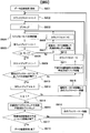
- step S902 the hologram recording / reproducing apparatus 10 pre-cures a predetermined area using the light beam emitted from the cure optical system 13 (step S903).
- the area pre-cured in step S903 is hereinafter referred to as a pre-cured area.
- step S903 hologram recording is performed using signal light and reference light.
- angle multiplexing is performed by changing the angle of the reference beam, and multiplex recording is performed on the same volume. That is, after step S903, multiple recording is performed for one book (step S904).
- pre-cure area to be pre-cured in step S903 is larger than the size of one book.
- the precure area and the book case are the same. That is, the pre-cure area pre-cured in step S903 is divided into areas of a predetermined size called books, and recording is performed for each book.
- step S904 the variable i is counted up (step S905). Thereafter, it is determined whether or not the variable i is greater than or equal to the j-th element of the predetermined array T, T [j] (step S906).
- the hologram recording / reproducing apparatus 10 drives the rotary motor 51 via the rotary motor control circuit 92 to move the book in the circumferential direction. (Step S907). This is realized by rotating the hologram recording medium 2 by driving the rotary motor 51 and relatively changing the positions of the pickup 11 and the cure optical system 13.
- step S907 the variable i is reset (step S908), and the process returns to step S904.
- step S904 the book is recorded at the position positioned in step S907.
- the variable i becomes a variable for counting the number of recorded books spread in the circumferential direction.
- variable i is equal to or greater than T [j] (Yes in step S906), the variable j is counted up (step S909), and then whether or not all the books have been recorded for the book case currently being recorded. Is determined (step S910).
- the hologram recording / reproducing apparatus 10 drives the radial transport unit 52 via the radial transport control circuit 93.
- the book is moved in the radial direction (step S911). This is realized by driving the radial transport unit 52 to transport the hologram recording medium 2 in the radial direction and relatively changing the positions of the pickup 11 and the cure optical system 13.
- variable j is reset, and the process returns to step S904.
- the book is recorded at the position positioned in step S911.
- the variable j becomes a variable for counting the lines where the recorded books have been laid out in the circumferential direction. This can be considered as a variable for counting the number of recorded books spread in the radial direction.
- step S910 When recording of all books is completed for the book case currently being recorded (Yes in step S910), the pre-cure area that has been pre-cured in step S903 is laid out with recorded books. That is, according to the above operation, bookcase recording is performed such that the hologram is recorded at a predetermined interval inside a predetermined area (bookcase) on the hologram recording medium.
- bookcase recording is performed according to an instruction from the controller 89.
- the rotary motor 51 and the radial transport unit 52 are driven via the rotary motor control circuit 92 and the radial transport control circuit 93 to change the recording position, and the reference is performed via the shutter control circuit 87.
- the bookcase recording is performed by controlling the irradiation time of light and signal light. That is, in this embodiment, the controller 89 functions as a means for performing bookcase recording.
- step S910 If YES in step S910, the variable k is counted up (step S913), and it is determined whether the variable k is equal to or greater than a predetermined numerical value N (step S914).
- the predetermined numerical value N is an integer of 2 or more.
- the hologram recording / reproducing apparatus 10 drives the rotary motor 51 via the rotary motor control circuit 92 and moves to the next book case ( Step S915). After step S915, the process returns to step S903. By this operation, the book case recording is similarly performed for the next book case.
- step S914 If the variable k is greater than or equal to the predetermined numerical value N (Yes in step S914), post-cure is performed using the light beam emitted from the cure optical system 13 for the recorded and post-cure unexecuted region (step S916). . After the counter reset in step S902, this condition is satisfied when all the N bookcases are laid out with recorded books, and postcuring is performed on the N bookcases in step S916.
- the area post-cured in step S916 is hereinafter referred to as a post-cure area. The order in which N bookcases are post-cured will be described later.
- step S916 it is determined whether recording has been completed for the entire surface of the hologram recording medium 2 (step S917). If recording has not been completed on the entire surface of the hologram recording medium 2 (No in step S917), the position of the hologram recording medium 2 is changed by driving the rotary motor 51 or the radial conveyance unit 52, and the next book case (Step S918). After step S918, the process returns to step S902.
- variable k When returning to step S902 after step S912, the variable k is reset. With the above operation, the variable k becomes a variable for counting the number of bookcases that have not been post-cured and are spread with recorded books.
- step S917 When recording is completed on the entire surface of the hologram recording medium 2 (Yes in step S917), the data recording process is terminated (step S919).
- post-cure is not performed immediately after the book case recording for the book case is completed.
- Perform a series of operations N times
- Precure for each bookcase and record the bookcase for that bookcase in other words, lay down the bookcase while recording the book
- Post-cure all N book cases This operation is repeated until recording is completed for the entire surface of the hologram recording medium 2.
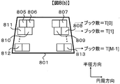
- FIG. 8 is a diagram showing the relationship between the pre-cure area and the book case, book, and post-cure area in the present embodiment.
- reference numerals 801, 802, and 803 denote book cases, which are the same as the pre-cure area in this embodiment.
- the book case has a trapezoidal shape. It is assumed that bookcase recording is performed for a total of N bookcases in the order of reference numeral 801, reference numeral 802,.
- Reference numeral 804 denotes a post-cure area, which is a set of the N book cases described above.
- FIG. 8B illustrates a single book case
- FIG. 8B illustrates the first book case 801 as an example.
- Reference numerals 805 to 813 denote books, respectively.
- the books are arranged at predetermined intervals.
- the set of books arranged in the horizontal direction in FIG. 8B is referred to as a row
- the set of books arranged in the vertical direction is referred to as a column, as in the definition of a mathematical matrix.
- the horizontal direction corresponds to the circumferential direction
- the vertical direction corresponds to the radial direction.
- the numerical value of the code attached to each book corresponds to the recording order of the book at the time of recording. That is, as the recording order of the books in the first book case 801, first the book 805 is recorded, then the book 806 is recorded, and similarly, the book 807 is moved to the right in the figure and recorded up to the book 807. After recording the book 807, the book 808 is moved downward to record the book 808, and recording is performed while moving from the book 809 to the book 811 in the left direction. Such an operation is repeated, and recording is performed while moving rightward from the book 812 to the book 813 at the lower end. As described above, the book recording order in this embodiment is recorded while the recording direction is alternately reversed left and right for each row.
- the number of books is different for each row in the bookcase. This number is managed in the array T [j] with the column index j as an argument.
- the variable M in FIG. 8B is the number of bookcase rows configured by laying out books. That is, the height of the book case is M times the height of the book.
- the book case is also a unit in which the recording order of the book is discontinuous.
- the single book case in the present embodiment has a trapezoidal shape as shown in FIG. 8B, it is arranged in the circumferential direction of the circular hologram recording medium 2 as shown in FIG. It is suitable for arranging a book along.
- step S916 the order in which N bookcases are post-cured in the post-cure process in step S916 will be described. Since the cure optical system 13 in this embodiment is common for pre-cure and post-cure, the area that can be cured at one time is common.
- the common configuration has an advantage that the number of parts can be reduced and the size can be reduced.
- the post-cure is performed by irradiating the light beam emitted from the cure optical system 13 in the order of the areas where bookcase recording was performed.
- the processing flow of FIG. 9 is used to further reduce the recording time. This will be described below.
- the rotation motor 51 is driven and the hologram recording medium 2 is driven at a speed higher than the speed at which the radial conveyance unit 52 is driven to move the hologram recording medium 2 by the distance between books.
- the speed of moving the book by the distance between books is faster.
- the hologram recording medium 2 is in contact with the rotary motor 51 and rotates integrally with the rotary shaft. For this reason, the load applied to the rotary motor 51 is only the hologram recording medium 2.
- the radial transport unit 52 is in contact with the rotary motor 51, the load applied to the radial transport unit 52 is the rotary motor 51 and the hologram recording medium 2. That is, the radial conveyance unit 52 is driven in a state where the weight of the rotary motor 51 is applied. As a result, the above speed difference occurs.
- the book case is rectangular and has A rows and B columns as shown in FIG. 10A, and the book recording order is the same as the book moving method of the first embodiment as shown in FIG. A similar case will be described as an example.
- the number of horizontal movements N1 of the book is
- the direction in which the book moves by driving the rotary motor 51 is set to the horizontal direction
- the direction in which the book moves by driving the radial conveyance unit 52 is set to the vertical direction.
- FIG. 9 which is the processing flow of the present embodiment, when laying down while recording a book on a trapezoidal book case, a loop that returns to step S904 when No is obtained in step S906, and a case where No is obtained in step S910. There are two loops, the loop returning to step S904. Of these, the inner loop, that is, the loop that returns to step S904 when No is determined in step S906 has a higher occurrence frequency.
- the book in the case of the inner loop, that is, the loop that returns to step S904 when No in step S906, the book is moved by driving the rotary motor 51.
- the radial transport unit 52 is driven to perform book movement. Thereby, the recording time can be shortened.
- the rotation motor 51 is also driven in the movement process to the next bookcase in step S915.
- the N bookcases are arranged along the circumferential direction.
- the rotation motor 51 is also driven at the time of irradiation N times. That is, with reference to FIG. 8B, in the post-cure process S916 of this embodiment, after the post-curing of the first book case 801, the rotary motor 51 is driven to post the second book case 802. Curing is performed and the operation of driving the rotary motor 51 is repeated.
- the rotation motor 51 is used for both the movement of the bookcase when sequentially recording the bookcase for each bookcase in FIG. 8A and the movement of the book when performing postcure for each bookcase.
- the configuration is performed by driving. With this configuration, the recording time can be further shortened.
- the bookcase has a trapezoidal shape.
- the book case has a rectangular shape as in the case of the first embodiment, and the processing flow of FIG. 9 is also effective. Due to the rectangular shape, the hologram recording media 2 cannot be arranged without gaps, and the recording capacity is reduced. However, it is possible to preferentially drive a drive unit having a high operating speed even in the case of a rectangular shape, which is effective in shortening the recording time.
- the rotary motor 51 and the radial transport unit are used as components for controlling the light beam irradiated from the pickup 11 and the reproduction reference light optical system 12 to be irradiated to a predetermined position of the hologram recording medium 2.
- the constituent elements are not limited thereto.
- the book moving direction (in the case of FIG. 10, the horizontal direction) frequently used in book case recording is matched with the direction in which the book can be moved by the drive unit (in the present embodiment, the rotary motor 51) having a high operating speed, thereby matching the book case.
- the direction in which book movement is possible is made to coincide with the book moving direction (the vertical direction in the case of FIG. 10), which is less frequently recorded, by the drive unit (in the case of the present embodiment, the radial direction conveyance unit 52) having a low operating speed.
- the direction in which the book can be moved by the drive unit having a high operating speed is a clockwise direction along the circumference or a counterclockwise direction along the circumference as described in the case of the second embodiment.
- the bookcase movement direction when performing bookcase recording on N bookcases is similarly controlled by the bookcase movement direction and the driving unit (in this embodiment, the rotary motor 51) having a high operation speed. Match the possible directions of movement.
- the drive unit in this embodiment, the rotary motor 51
- the rotary motor 51 having a high operation speed is driven to irradiate from the cure optical system.
- the position of the light beam to be moved is moved.
- the device based on the above device design has the following features.
- the direction of movement between adjacent book cases is determined by the driving means that is driven most frequently among the driving means driven in the book case recording process on the hologram recording medium.
- the position of coincides with the movable direction.
- the direction of movement between adjacent bookcases is the circumferential direction.
- the direction in which the position on the hologram recording medium is moved by the rotary motor 51 which is the driving means that is most frequently driven when performing bookcase recording is also the circumferential direction.
- recording processing can be performed in consideration of dark reaction time and post-cure timeout, and appropriate recording on the hologram recording medium and shortening of the recording time can be realized at the same time. Further, the post-cure area can be widened, and the recording capacity can be increased by reducing the dummy area.
- the medium transport unit 50 in the first embodiment as a mechanism for controlling the light beam irradiated from the pickup 11 and the cure optical system 13 to be irradiated to a predetermined position of the hologram recording medium, for example, the medium transport unit 50 in the first embodiment.
- the hologram recording medium is transported.
- this mechanism is not limited to this.
- the hologram recording medium may be fixed, and the pickup 11 and the cure optical system 13 may be transported.
- the recording is performed by angle multiplexing by changing the incident angle of the reference beam.
- the present invention can be similarly applied when a multiplexing method other than angle multiplexing is used.
- the present invention can be similarly applied to the case of hologram recording without performing multiple recording.
- the book case in the above embodiment has a rectangular shape in the case of the first embodiment and a trapezoid shape in the case of the second embodiment, but is not limited thereto.
- the book case has an approximately rectangular shape.
- the above operation can be easily realized. That is, if the book case has a substantially quadrangular shape, it will be described with reference to FIG. 6B that there are two operations: an operation of recording a book in the horizontal direction and an operation of moving the book in the vertical direction perpendicular thereto. There is an advantage that can be realized by repeating one operation.
- FIG. 6B there are two operations: an operation of recording a book in the horizontal direction and an operation of moving the book in the vertical direction perpendicular thereto.
- the book case 8B is the same because the circumferential direction and the radial direction are orthogonal to each other.
- the book case is a quadrangle
- the book case is a quadrangle formed by a set of recorded books as a result of book recording while scanning a position on the hologram recording medium using a predetermined axis and an axis orthogonal thereto. It can be rephrased as an area.
- the predetermined axis and the axis perpendicular thereto are axes on a plane parallel to the surface of the hologram recording medium 1.
- the recording order of books is greatly different between adjacent books at the boundary of the book case.
- the book adjacent to the book 607 at the boundary of the book case is the book at the upper left corner of the book case 602 adjacent to the book case 601, and the book recording is performed.
- the order is a book recorded following the book 613.
- the size of the bookcases is not specifically mentioned.
- all the bookcases existing on the hologram recording medium may be the same size or different sizes may be mixed.
- the book case is recorded on the book case, and this is repeated N times.
- the bookcase recording is performed on the area 601 immediately after the area 601 is precured, and the bookcase recording on the area 602 is performed immediately after the area 602 is precured.
- the order of precure and bookcase recording may be other than this.
- the following operation may be performed.
- the area 601 is pre-cured
- the area 602 is also pre-cured, and then the book case recording for the area 601 is performed, and then the book case recording for the area 602 is performed.
- two book cases 601 and 602 are pre-cured, and book cases are performed in the order of 601 and 602.
- Pre-cure and book case recording are performed using two book cases as one unit.
- the above-described process of performing the pre-cure and book case recording for every two book cases is repeated N / 2 times. Even with this operation, the first to third problems can be solved similarly.
- a region to be pre-cured by one pre-curing process is a single book case (for example, region 601), and a region to be post-cured by one post-curing process is N times the region (region 604). )Met.
- first, 601, 602,..., 603 are pre-cured, and then the book 601, 602,. You may post-cure in the order of.
- the area to be pre-cured by one pre-curing process is not a single book case, and is an area N times that of 604, so that the area to be post-cured by one post-curing process is It will be the same. Even with this operation, the first to third problems can be solved similarly. However, as described above, if the pre-cure region is too wide, there is a possibility that a problem may occur. Therefore, the selection of the numerical value N that affects the area of the pre-cure region also requires consideration of this point.
- the cure optical system irradiates a single pre-cure area (for example, area 601) with a light beam.
- a configuration may be adopted in which a light beam is uniformly irradiated on the entire pre-cured region, and the entire pre-cured region is pre-cured by irradiating a single light beam.
- the pre-cure may be performed by dividing the pre-cure region into a plurality of regions and moving the light beam irradiation position to each region. The same applies to post-cure.
- the book case and the pre-cure area are the same.
- the book case and the pre-cure area do not have to be the same. That is, in the above embodiment, the book movement and the book recording are performed so that the inside of the precure area is spread with a book.
- the book movement delimiter ie, the book case
- the precure or postcure area It does not have to be.
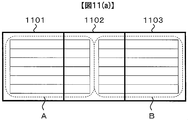
- FIG. 11 (a) A modified example in this case will be described with reference to FIG.
- Three areas 1101, 1102, and 1103 in FIG. 11A indicate adjacent precure areas.
- a horizontally long rectangle drawn inside broken lines indicated by A and B in FIG. 11A indicates a book in which the books are arranged in a row horizontally.
- a book movement delimiter (horizontal direction) in three adjacent precured areas 1101, 1102, and 1103 is 1.5 times the width of a single precured area. It is also possible to stop the book recording and move to the next line.
- FIG. 11 (a) after pre-curing all three pre-cure areas, the portion of the book indicated by A in FIG. 11 (a) is recorded, followed by the portion of the book indicated by B in FIG. 11 (a). The same effect can be obtained even when the post cure is performed in the order of 1101, 1102, and 1103 after that.
- the bookcase recording is performed for the adjacent bookcase after the bookcase recording is performed and before the dark reaction time of the book in the bookcase elapses.
- the area in which the hologram is recorded after the book case recording and before the dark reaction time of the book in the book case elapses does not necessarily have to be a bookcase partition.
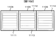
- FIG. 11B A modification in this case will be described with reference to FIG. Three areas 1104, 1105, and 1106 in FIG. 11B indicate adjacent pre-cure areas.
- a horizontally long rectangle drawn inside the broken line indicates a book in which the books are arranged in a row horizontally.
- the broken line portion 1111 to the broken line portion 1114 indicate a set of books, and the numerical value of the code attached to the broken line portion corresponds to the recording order.
- FIG. 11B first, the area 1104 and the area 1105 are precured, the book of the broken line part 1111 and the broken line part 1112 is recorded, and then the area 1104 is post-cured. After that, the area 1106 is pre-cured, the book of the area of the broken line part 1113 and the broken line part 1114 is recorded, the area 1105 is post-cured, and then the area 1106 is post-cured.
- the same effect can be obtained.
- the dark reaction time of the book in the broken line part 1111 has elapsed when the recording of the book in the area of the broken line part 1112 has been completed, and when the post cure for the area 1105 has been completed, It is assumed that the dark reaction time has elapsed.
- region of the broken line part 1112 can be lengthened by enlarging the size of a book case, it can take such a form by design of the size of a book case.
- a unit for laying a book is defined as a book case
- a unit (book case) for laying a book in FIG. 11B corresponds to, for example, a broken line portion 1111.
- the set of books included in the area including the broken line part 1112 and the broken line part 1113 is also an area of the same size as the broken line part 1111 and can be considered as a book case.
- the area in which the hologram is recorded while waiting for the dark reaction time of the book case at the broken line portion 1111 is all the books inside the area including the broken line portion 1112 and the broken line portion 1113.
- the area in which the hologram is recorded while waiting for the dark reaction time of the bookcase in the broken line portion 1111 may be only a part of the adjacent bookcase, that is, the area indicated by the broken line portion 1112. .
- the areas where the post-cure process is continuously performed need not be all areas that have been recorded and have not been post-cured.
- the areas that have been recorded at the timing of post-curing the area 1104 and have not been post-cured are the broken line part 1111 and the broken line part 1112, but only the broken line part 1111 is post-cured.
- the post-cure is performed on the recorded and post-cure unexecuted area, but the present invention is not limited to this.
- the most basic configuration relating to the present invention is that the first unit is defined when a unit for laying a book is defined as a book case (for example, A or B in the case of FIG. 11).
- the book is recorded in an area different from that of the first book case within the time until the post-cure is performed on the first book case after the book case is laid down while recording the book.
- the area different from the first bookcase mentioned here does not necessarily have to be a bookcase partition.
- the post-cure for the first book case can be performed continuously. Suitable recording can be realized.
- the most basic advantage of the present invention is that a suitable recording can be achieved by recording a book in another area while waiting for the dark reaction time after recording the first book case. is there.
- One reason for this is that the book can be recorded continuously without waiting for the dark reaction time. Therefore, the most basic configuration related to the present invention described above can be rephrased as a configuration in which the waiting time is assigned to the operation of recording a book in another area in consideration of the dark reaction time of the first book case. it can.
- the unit to be recorded within the time is also a bookcase unit, which is a simple and easy to manage implementation.
- the “area different from the first bookcase” refers to the N ⁇ 1 bookcase areas moved in step S509 (area 602,..., Area 604 in FIG. 6A). ).
- the book recording in this area is executed in steps S504 to S506 which are executed again after returning to step 503 via step S509.
- a unit for laying out a book is defined as a book case, and a book case recording operation is referred to as book case recording.
- Bookcase recording without using the expression bookcase, recording holograms while changing the recording position so that holograms with recorded information are arranged at predetermined intervals inside the predetermined area. It can be explained as a process of performing. Therefore, the process of performing bookcase recording can also be called area recording processing.
- the vertical length of the book case (604 in FIG. 6) is larger than twice the vertical length of the book (eg, 605 in FIG. 6), and the horizontal length of the book case is the horizontal length of the book. It is preferably larger than 2 times.
- the size of the book case is preferably 2 ⁇ 2 or more based on the size of the book.
- the sizes of the pre-cure area and the post-cure area are also 2 ⁇ 2 or more based on the book size.
- the first point is that it is easy to configure the cure optical system 13 that generates light for pre-curing. This is because, for example, the optical system becomes more difficult to design as the aspect ratio of the region to which light for pre-curing is irradiated becomes larger (for example, one book is vertical and 20 books are horizontal).
- the second point is that the total recording time can be shortened because a larger area can be simultaneously precured.
- the third point is that the above-mentioned problem as the “third problem” can be solved. This is because the longer the vertical and horizontal lengths of the post-cure area, the smaller the total number of books in which dummy information to be spread around the post-cure area is recorded.
- the first point contributes to the ease of designing the optical system
- the second point reduces the recording time
- the third point contributes to the improvement of the recording capacity. Therefore, from a comprehensive viewpoint, the size of the book case is preferably 2 ⁇ 2 or more based on the size of the book.
- Patent Document 2 discloses a configuration in which fixing is performed simultaneously with recording.
- a hologram is recorded concentrically called “track”, and post-cure is performed along the track. That is, the distance between the “tracks” corresponds to the length of the horizontal side of “book” in the expression of the present embodiment, and one side of the region that is post-cured at a time in the document is represented in the expression of the present embodiment. Equal to the length of the vertical side of the “book”. Therefore, in the configuration in this document, the post-cure area is not 2 ⁇ 2 or more on the basis of the size of the book, and the above three effects cannot be obtained.
- a feature common to the present invention is that an operation of continuously performing a post-cure in an area larger than the book case is included.
- FIG. 11B which is a modified example, post cure is performed on the region 1106 following the region 1105 in the second post cure, and the region where the post cure is continuously performed is larger than the book case.
- the post-cure area is a set of a plurality of book cases as in the embodiment described in the embodiment.
- the pre-curing process is not necessarily performed, but the recording quality can be improved by performing the pre-curing process.
- the present invention is not limited to the above-described embodiments, and includes various modifications in addition to the above-described modifications.
- the above-described embodiments have been described in detail for easy understanding of the present invention, and are not necessarily limited to those having all the configurations described.
- a part of the configuration of one embodiment can be replaced with the configuration of another embodiment, and the configuration of another embodiment can be added to the configuration of one embodiment.
- Each of the above-described configurations, functions, processing units, processing means, and the like may be realized by hardware by designing a part or all of them with, for example, an integrated circuit.
- Each of the above-described configurations, functions, and the like may be realized by software by interpreting and executing a program that realizes each function by the processor.
- Information such as programs, tables, and files for realizing each function can be stored in a memory, a hard disk, a recording device such as an SSD (Solid State Drive), or a recording medium such as an IC card, an SD card, or a DVD.
- the control lines and information lines indicate what is considered necessary for the explanation, and not all the control lines and information lines on the product are necessarily shown. Actually, it may be considered that almost all the components are connected to each other.
- SYMBOLS 1 ... Hologram recording medium, 2 ... Hologram recording medium, 10 ... Hologram recording / reproducing apparatus, 11 ... Pickup, 12 ... Reference light optical system for reproduction, 13 ... Cure optical system, 14 ...
- External control device 92 ... Rotary motor control circuit, 93 ... Radial direction conveyance control circuit, 201 ... light source, 203 ... shutter, 206 ... signal light, 207 ... reference light, 212 ... Spatial light modulator, 214 ... Spatial filter, 215 ... objective lens, 220 ... actuator, 223 ... Actuator, 224 ... Mirror, 225 ... Photodetector
Landscapes
- Physics & Mathematics (AREA)
- General Physics & Mathematics (AREA)
- Optical Recording Or Reproduction (AREA)
- Holo Graphy (AREA)
Abstract
Description
データ記録処理を開始すると(ステップS501)、まずカウントを行う変数kをゼロにリセットし、k=0とする(ステップS502)。
以上の動作により変数iは、円周方向に敷き詰めた記録済みブックの数をカウントする変数となる。



また、制御線や情報線は説明上必要と考えられるものを示しており、製品上必ずしも全ての制御線や情報線を示しているとは限らない。実際には殆ど全ての構成が相互に接続されていると考えてもよい。
12…再生用参照光光学系、13…キュア光学系、14…ディスク回転角度検出用光学系、
50…媒体搬送部、51…回転モータ、52…半径方向搬送部、
81…媒体搬送制御回路、82…光源駆動回路、83…サーボ信号生成回路、
84…サーボ制御回路、85…信号処理回路、86…信号生成回路、
87…シャッタ制御回路、88…媒体搬送制御回路、
89…コントローラ、90…入出力制御回路、91…外部制御装置、
92…回転モータ制御回路、93…半径方向搬送制御回路、
201…光源、203…シャッタ、206…信号光、207…参照光、
212…空間光変調器、214…空間フィルタ、
215…対物レンズ、220…アクチュエータ、
223…アクチュエータ、
224…ミラー、225…光検出器
Claims (18)
- 信号光と参照光をホログラム記録媒体に照射して情報の記録を行うホログラム記録装置であって、
前記信号光および前記参照光が照射される位置を変更して前記ホログラム記録媒体上の記録位置を変更する記録位置変更手段と、
前記記録位置変更手段を用いて前記記録位置を変更すると共に前記信号光と前記参照光の照射を制御することにより、前記ホログラム記録媒体上の所定領域の内部に、情報が記録されたホログラムを所定の間隔で配置する領域記録処理を行う領域記録処理手段と、
前記情報の記録が完了した領域に対して所定の光ビームを照射するポストキュア処理を行うポストキュア処理手段とを備え、
前記領域記録手段が前記ホログラム記録媒体の第一の所定領域に対して第一の前記領域記録処理を行った後、前記ポストキュア手段が前記第一の所定領域に対する前記ポストキュア処理を行うまでの時間内に、
前記第一の所定領域と異なる領域に前記信号光と前記参照光を照射して情報の記録を行うことを特徴とするホログラム記録装置。 - 信号光と参照光をホログラム記録媒体に照射して情報の記録を行うホログラム記録装置であって、
前記信号光および前記参照光が照射される位置を変更して前記ホログラム記録媒体上の記録位置を変更する記録位置変更手段と、
前記記録位置変更手段を用いて前記記録位置を変更すると共に前記信号光と前記参照光の照射を制御することにより、前記ホログラム記録媒体上の所定領域の内部に、情報が記録されたホログラムを所定の間隔で配置する領域記録処理を行う領域記録処理手段と、
前記情報の記録が完了した領域に対して所定の光ビームを照射するポストキュア処理を行うポストキュア処理手段とを備え、
前記領域記録手段が前記ホログラム記録媒体の第一の所定領域に対して第一の前記領域記録処理を行った後、前記ポストキュア手段が前記第一の所定領域に対する前記ポストキュア処理を行うまでの時間内に、
前記第一の所定領域と異なる領域に対する前記領域記録処理を少なくとも1回行うことを特徴とするホログラム記録装置。 - 請求項1または請求項2に記載のホログラム記録装置であって、
前記領域記録処理手段が前記ホログラムを所定の間隔で配置する前記所定領域は、前記ホログラムを所定の方向に2以上かつ前記所定の方向と直行する方向に2以上配置した、略四角形の形状であることを特徴とするホログラム記録装置。 - 請求項1または請求項2に記載のホログラム記録装置であって、
前記時間内に、前記第一の所定領域と異なる領域に対する前記領域記録処理を少なくとも1回行い、
前記ポストキュア手段が前記第一の所定領域に対する前記ポストキュア処理に続けて、
前記時間内に前記領域記録処理を行った領域に対する前記ポストキュア処理を行うことを特徴とするホログラム記録装置。 - 請求項1または請求項2に記載のホログラム記録装置であって、
複数の所定領域に対する前記領域記録処理を順に行った後、
前記複数の所定領域に関して、前記領域記録処理を行った順に、前記ポストキュア処理手段が前記ポストキュア処理を行うことを特徴とするホログラム記録装置。 - 請求項2に記載のホログラム記録装置であって、
前記時間内に前記領域記録処理を行う領域は、前記第一の所定領域に隣接することを特徴とするホログラム記録装置。 - 請求項2に記載のホログラム記録装置であって、
前記ポストキュア手段が前記第一の所定領域に対する前記ポストキュア処理に続けて、
前記時間内に前記領域記録処理を行った領域の少なくとも一部に対する前記ポストキュア処理を行うことを特徴とするホログラム記録装置。 - 請求項2に記載のホログラム記録装置であって、
前記記録位置変更手段は、前記ホログラム記録媒体を回転させる回転手段と前記回転手段の回転方向と直交する半径方向に前記ホログラム記録媒体を搬送する半径方向搬送手段から構成され、
前記第一の所定領域から、前記第一の前記領域に対する記録処理の直後に前記領域記録処理を行う第二の所定領域に移動する方向は、前記第一の所定領域から前記回転手段により前記記録位置が移動可能な方向と一致することを特徴とするホログラム記録装置。 - 請求項2に記載のホログラム記録装置であって、
前記記録位置変更手段は、少なくとも2つの駆動手段から構成され、
前記第一の所定領域から、前記第一の前記領域記録処理の直後に前記領域記録処理を行う第二の所定領域に移動する方向は、
前記領域記録処理において最も駆動する頻度の高い前記駆動手段により、前記記録位置が移動可能な方向と一致することを特徴とするホログラム記録装置。 - 請求項2に記載のホログラム記録装置であって、
前記ポストキュア処理手段が連続して前記ポストキュア処理を行う領域は、前記領域記録処理を行う領域よりも広いことを特徴とするホログラム記録装置。 - 請求項2に記載のホログラム記録装置であって、
前記ポストキュア処理手段が連続して前記ポストキュア処理を行う領域は、前記ポストキュア処理より以前に前記領域記録処理を行った領域の集合であることを特徴とするホログラム記録装置。 - 請求項2に記載のホログラム記録装置であって、
前記ポストキュア処理手段が連続して前記ポストキュア処理を行う領域同士の間には、ダミーの情報を記録したホログラムを所定の幅、配置して記録することを特徴とするホログラム記録装置。 - 請求項2に記載のホログラム記録装置であって、
複数の所定領域に対する前記領域記録処理を順に行った後に、前記ポストキュア処理手段が前記複数の所定領域に対する前記ポストキュア処理を行う一連の動作を行い、
前記一連の動作を繰り返すことで前記ホログラム記録媒体に対する情報の記録を行い、
前記ポストキュア処理を行う領域同士の間にはダミーの情報を記録したホログラムを記録し、
前記一連の動作において前記領域記録処理が行われる前記複数の所定領域同士の間にはダミーの情報を記録したホログラムを記録しないことを特徴とするホログラム記録装置。 - 請求項2に記載のホログラム記録装置であって、
前記ポストキュア処理において照射される光ビームは、前記信号光及び前記参照光よりもコヒーレンスが低いことを特徴とするホログラム記録装置。 - 請求項2に記載のホログラム記録装置であって、
前記情報の記録が行われていない領域に対して所定の光ビームを照射するプリキュア処理を行うプリキュア処理手段を備え、
前記プリキュア処理において照射される光ビームを生成する光学系は、前記ポストキュア処理において照射される光ビームを生成する光学系と同一であることを特徴とするホログラム記録装置。 - 信号光と参照光をホログラム記録媒体に照射して情報の記録を行うホログラム記録方法であって、
前記信号光と前記参照光の照射位置と照射時間を制御しながらホログラムの記録を行って、前記ホログラム記録媒体の第一の所定領域の内部に、情報が記録されたホログラムを所定の間隔で配置するステップと、
前記第一の所定領域とは異なる領域に前記信号光と前記参照光を照射して前記情報の記録を行うステップと、
前記第一の所定領域に対して所定の光ビームを照射するポストキュア処理を行うステップを有するホログラム記録方法。 - 信号光と参照光をホログラム記録媒体に照射して情報の記録を行うホログラム記録方法であって、
前記信号光と前記参照光の照射位置と照射時間を制御しながらホログラムの記録を行って、前記ホログラム記録媒体の第一の所定領域の内部に、情報が記録されたホログラムを所定の間隔で配置するステップと、
前記第一の所定領域とは異なる領域に対する前記領域記録処理を少なくとも1回行うステップと、
前記第一の所定領域に対するポストキュア処理を行うステップを有するホログラム記録方法。 - 請求項16または請求項17に記載のホログラム記録方法であって、
前記信号光と前記参照光の参照位置と照射時間を制御しながらホログラムの記録を行って、前記ホログラム記録媒体の所定領域の内部に、情報が記録されたホログラムを所定の間隔で配置する動作を複数回反復するステップと、
前記複数回の反復によって情報の記録された前記複数の所定領域に関して、反復を行った順に、前記ポストキュア処理を行うステップを有するホログラム記録方法。
Priority Applications (4)
| Application Number | Priority Date | Filing Date | Title |
|---|---|---|---|
| PCT/JP2012/072099 WO2014033895A1 (ja) | 2012-08-31 | 2012-08-31 | ホログラム記録装置及びホログラム記録方法 |
| CN201280075293.9A CN104584129A (zh) | 2012-08-31 | 2012-08-31 | 全息记录装置和全息记录方法 |
| US14/421,458 US9390742B2 (en) | 2012-08-31 | 2012-08-31 | Hologram recording device and hologram recording method |
| JP2014532666A JPWO2014033895A1 (ja) | 2012-08-31 | 2012-08-31 | ホログラム記録装置及びホログラム記録方法 |
Applications Claiming Priority (1)
| Application Number | Priority Date | Filing Date | Title |
|---|---|---|---|
| PCT/JP2012/072099 WO2014033895A1 (ja) | 2012-08-31 | 2012-08-31 | ホログラム記録装置及びホログラム記録方法 |
Publications (1)
| Publication Number | Publication Date |
|---|---|
| WO2014033895A1 true WO2014033895A1 (ja) | 2014-03-06 |
Family
ID=50182743
Family Applications (1)
| Application Number | Title | Priority Date | Filing Date |
|---|---|---|---|
| PCT/JP2012/072099 Ceased WO2014033895A1 (ja) | 2012-08-31 | 2012-08-31 | ホログラム記録装置及びホログラム記録方法 |
Country Status (4)
| Country | Link |
|---|---|
| US (1) | US9390742B2 (ja) |
| JP (1) | JPWO2014033895A1 (ja) |
| CN (1) | CN104584129A (ja) |
| WO (1) | WO2014033895A1 (ja) |
Cited By (2)
| Publication number | Priority date | Publication date | Assignee | Title |
|---|---|---|---|---|
| WO2015129016A1 (ja) * | 2014-02-28 | 2015-09-03 | 日立コンシューマエレクトロニクス株式会社 | 情報記録再生装置および情報記録方法 |
| JP2017147012A (ja) * | 2016-02-19 | 2017-08-24 | 三菱ケミカル株式会社 | ホログラム記録媒体の記録方法及び記録装置 |
Families Citing this family (1)
| Publication number | Priority date | Publication date | Assignee | Title |
|---|---|---|---|---|
| US12033680B1 (en) * | 2023-03-07 | 2024-07-09 | National Central University | Method for reading and writing with holographic storage system and holographic storage system |
Citations (4)
| Publication number | Priority date | Publication date | Assignee | Title |
|---|---|---|---|---|
| JP2006243241A (ja) * | 2005-03-02 | 2006-09-14 | Sony Corp | ホログラム記録装置およびホログラム記録方法 |
| JP2009043369A (ja) * | 2007-08-10 | 2009-02-26 | Sony Corp | 記録装置、記録方法 |
| JP2009289384A (ja) * | 2008-06-02 | 2009-12-10 | Hitachi Ltd | 光情報記録再生装置及び光情報記録方法 |
| JP2010181760A (ja) * | 2009-02-09 | 2010-08-19 | Hitachi Ltd | 光情報記録方法および記録装置 |
Family Cites Families (3)
| Publication number | Priority date | Publication date | Assignee | Title |
|---|---|---|---|---|
| JP3566033B2 (ja) * | 1997-06-26 | 2004-09-15 | 株式会社東芝 | ホログラムメモリ装置およびこのホログラムメモリ装置により記録対象情報を記録および再生する方法 |
| KR20070006686A (ko) | 2003-12-12 | 2007-01-11 | 디시이 아프릴리스, 인코포레이티드 | 홀로그래픽 데이터 저장시스템에서의 홀로그래픽 미디어의정착방법과 장치 |
| JP5020090B2 (ja) * | 2005-10-17 | 2012-09-05 | パナソニック株式会社 | ホログラム多重記録装置とその方法 |
-
2012
- 2012-08-31 WO PCT/JP2012/072099 patent/WO2014033895A1/ja not_active Ceased
- 2012-08-31 JP JP2014532666A patent/JPWO2014033895A1/ja active Pending
- 2012-08-31 CN CN201280075293.9A patent/CN104584129A/zh active Pending
- 2012-08-31 US US14/421,458 patent/US9390742B2/en not_active Expired - Fee Related
Patent Citations (4)
| Publication number | Priority date | Publication date | Assignee | Title |
|---|---|---|---|---|
| JP2006243241A (ja) * | 2005-03-02 | 2006-09-14 | Sony Corp | ホログラム記録装置およびホログラム記録方法 |
| JP2009043369A (ja) * | 2007-08-10 | 2009-02-26 | Sony Corp | 記録装置、記録方法 |
| JP2009289384A (ja) * | 2008-06-02 | 2009-12-10 | Hitachi Ltd | 光情報記録再生装置及び光情報記録方法 |
| JP2010181760A (ja) * | 2009-02-09 | 2010-08-19 | Hitachi Ltd | 光情報記録方法および記録装置 |
Cited By (2)
| Publication number | Priority date | Publication date | Assignee | Title |
|---|---|---|---|---|
| WO2015129016A1 (ja) * | 2014-02-28 | 2015-09-03 | 日立コンシューマエレクトロニクス株式会社 | 情報記録再生装置および情報記録方法 |
| JP2017147012A (ja) * | 2016-02-19 | 2017-08-24 | 三菱ケミカル株式会社 | ホログラム記録媒体の記録方法及び記録装置 |
Also Published As
| Publication number | Publication date |
|---|---|
| US20150221331A1 (en) | 2015-08-06 |
| CN104584129A (zh) | 2015-04-29 |
| US9390742B2 (en) | 2016-07-12 |
| JPWO2014033895A1 (ja) | 2016-08-08 |
Similar Documents
| Publication | Publication Date | Title |
|---|---|---|
| CN101609697A (zh) | 光信息记录装置及方法、光信息记录再现装置及方法 | |
| KR20100080459A (ko) | 광 데이터 저장 디스크를 복제하는 방법 | |
| JP5753768B2 (ja) | 光情報記録装置、光情報再生装置、光情報記録再生装置、光情報記録方法、光情報再生方法および光情報記録再生方法 | |
| JP5581111B2 (ja) | 光情報再生装置および光情報再生方法 | |
| US9013972B2 (en) | Optical information recording and reproducing method and device | |
| WO2014033895A1 (ja) | ホログラム記録装置及びホログラム記録方法 | |
| US8699311B2 (en) | Optical information recording/reproducing apparatus, optical information reproducing apparatus, optical information recording/reproducing method and optical information reproducing method | |
| US8174951B2 (en) | Optical information recording method and apparatus | |
| JP5868494B2 (ja) | 光情報記録再生装置、および光情報記録再生方法、および再生装置 | |
| JP5993956B2 (ja) | 光情報記録再生装置および光情報記録再生方法 | |
| WO2015011744A1 (ja) | 光情報記録装置、光情報再生装置、光情報記録方法および再生位置ずれ検出方法 | |
| JPWO2014091531A1 (ja) | 光情報再生装置及び光情報再生方法 | |
| JP5953284B2 (ja) | 光情報記録媒体、光情報記録装置、光情報記録方法、光情報再生装置、光情報再生方法。 | |
| JP5414861B2 (ja) | 光情報記録装置、光情報記録方法、光情報記録再生装置および光情報記録再生方法 | |
| JP6078634B2 (ja) | 光情報再生装置および光情報記録再生装置 | |
| JPWO2015083246A1 (ja) | 光情報再生装置及び光情報再生方法 | |
| WO2015083247A1 (ja) | 光情報記録装置、および光情報記録方法 | |
| JPWO2014167620A1 (ja) | 光情報再生装置及び光情報再生方法 | |
| WO2016199229A1 (ja) | ホログラム記録再生装置 | |
| JP2015082327A (ja) | 光情報再生装置、光情報再生方法および光情報記録方法 | |
| JP2016071918A (ja) | 光情報記録再生装置および光情報再生方法 | |
| WO2015033456A1 (ja) | 光情報記録装置、光情報再生装置、光情報記録方法および光情報再生方法 | |
| WO2014091530A1 (ja) | 情報記録再生装置及び記録方法 | |
| WO2013175526A1 (ja) | 光情報再生装置及び光情報再生方法 |
Legal Events
| Date | Code | Title | Description |
|---|---|---|---|
| 121 | Ep: the epo has been informed by wipo that ep was designated in this application |
Ref document number: 12883628 Country of ref document: EP Kind code of ref document: A1 |
|
| ENP | Entry into the national phase |
Ref document number: 2014532666 Country of ref document: JP Kind code of ref document: A |
|
| WWE | Wipo information: entry into national phase |
Ref document number: 14421458 Country of ref document: US |
|
| NENP | Non-entry into the national phase |
Ref country code: DE |
|
| 122 | Ep: pct application non-entry in european phase |
Ref document number: 12883628 Country of ref document: EP Kind code of ref document: A1 |