WO2014027561A1 - 液体用容器及びこれを用いた液面レベルの測定方法 - Google Patents
液体用容器及びこれを用いた液面レベルの測定方法 Download PDFInfo
- Publication number
- WO2014027561A1 WO2014027561A1 PCT/JP2013/070486 JP2013070486W WO2014027561A1 WO 2014027561 A1 WO2014027561 A1 WO 2014027561A1 JP 2013070486 W JP2013070486 W JP 2013070486W WO 2014027561 A1 WO2014027561 A1 WO 2014027561A1
- Authority
- WO
- WIPO (PCT)
- Prior art keywords
- liquid
- container
- ultrasonic sensor
- ultrasonic
- reflecting
- Prior art date
Links
Images

Classifications
-
- G—PHYSICS
- G01—MEASURING; TESTING
- G01F—MEASURING VOLUME, VOLUME FLOW, MASS FLOW OR LIQUID LEVEL; METERING BY VOLUME
- G01F23/00—Indicating or measuring liquid level or level of fluent solid material, e.g. indicating in terms of volume or indicating by means of an alarm
- G01F23/22—Indicating or measuring liquid level or level of fluent solid material, e.g. indicating in terms of volume or indicating by means of an alarm by measuring physical variables, other than linear dimensions, pressure or weight, dependent on the level to be measured, e.g. by difference of heat transfer of steam or water
- G01F23/28—Indicating or measuring liquid level or level of fluent solid material, e.g. indicating in terms of volume or indicating by means of an alarm by measuring physical variables, other than linear dimensions, pressure or weight, dependent on the level to be measured, e.g. by difference of heat transfer of steam or water by measuring the variations of parameters of electromagnetic or acoustic waves applied directly to the liquid or fluent solid material
- G01F23/296—Acoustic waves
- G01F23/2962—Measuring transit time of reflected waves
-
- B—PERFORMING OPERATIONS; TRANSPORTING
- B65—CONVEYING; PACKING; STORING; HANDLING THIN OR FILAMENTARY MATERIAL
- B65D—CONTAINERS FOR STORAGE OR TRANSPORT OF ARTICLES OR MATERIALS, e.g. BAGS, BARRELS, BOTTLES, BOXES, CANS, CARTONS, CRATES, DRUMS, JARS, TANKS, HOPPERS, FORWARDING CONTAINERS; ACCESSORIES, CLOSURES, OR FITTINGS THEREFOR; PACKAGING ELEMENTS; PACKAGES
- B65D25/00—Details of other kinds or types of rigid or semi-rigid containers
- B65D25/02—Internal fittings
-
- G—PHYSICS
- G01—MEASURING; TESTING
- G01F—MEASURING VOLUME, VOLUME FLOW, MASS FLOW OR LIQUID LEVEL; METERING BY VOLUME
- G01F23/00—Indicating or measuring liquid level or level of fluent solid material, e.g. indicating in terms of volume or indicating by means of an alarm
- G01F23/22—Indicating or measuring liquid level or level of fluent solid material, e.g. indicating in terms of volume or indicating by means of an alarm by measuring physical variables, other than linear dimensions, pressure or weight, dependent on the level to be measured, e.g. by difference of heat transfer of steam or water
- G01F23/28—Indicating or measuring liquid level or level of fluent solid material, e.g. indicating in terms of volume or indicating by means of an alarm by measuring physical variables, other than linear dimensions, pressure or weight, dependent on the level to be measured, e.g. by difference of heat transfer of steam or water by measuring the variations of parameters of electromagnetic or acoustic waves applied directly to the liquid or fluent solid material
- G01F23/296—Acoustic waves
Definitions
- the present invention relates to a liquid container capable of measuring the liquid level of the liquid stored inside the container from the outside, and a liquid level measurement method using the liquid container.
- Patent Document 1 discloses an ultrasonic sensor that is brought into contact with an outer side surface of a container, a displacement unit that displaces the ultrasonic sensor in a vertical direction along the outer side surface of the container, and an ultrasonic wave emitted into the container.
- a liquid level detecting device including a liquid level detecting means for detecting a liquid level based on a change in an output level of a reflected wave.
- Patent Document 2 discloses a piezoelectric element attached to an outer bottom surface of a tank via a matching layer, an ultrasonic wave emitting means for vibrating the piezoelectric element in the thickness direction to emit ultrasonic waves into the tank, The ultrasonic wave receiving means for receiving the ultrasonic wave reflected and returned by the liquid level of the liquid stored in the tank, and the time period from when the ultrasonic wave is emitted until it is received is stored in the tank There is disclosed a liquid level detecting device including a liquid level detecting means for detecting an absolute value of a liquid level.
- Patent Document 3 discloses an ultrasonic wave for obtaining a liquid surface level in which an ultrasonic transmitter / receiver is provided at the bottom of a housing in the range of the measurement chamber outside the housing having the measurement chamber and the inlet chamber connected to each other. A sensor is disclosed.
- the liquid level detecting device disclosed in Patent Document 1 repeats the operation of irradiating an ultrasonic wave by displacing the ultrasonic sensor and detecting whether or not there is liquid. There was a problem that it took time to measure.
- the liquid level detection device disclosed in Patent Document 2 and the ultrasonic sensor disclosed in 3 since the sensor is installed at the bottom, the liquid level of the liquid stored inside the container is constant. There was a problem that measurement could not be performed when the value was below the value. This is because the ultrasonic sensor has a non-measurable region (sometimes referred to as a dead zone).
- the problem to be solved by the present invention is to provide a liquid container capable of measuring the liquid level in a short time without being affected by the dead zone of the ultrasonic sensor even when the liquid level is low. It is to provide.
- the present invention relates to a container main body for storing a liquid, an ultrasonic sensor that is in contact with the outer wall of the container main body and that transmits ultrasonic waves into the liquid, and an inner bottom portion of the container main body. And reflecting means for reflecting ultrasonic waves transmitted from the ultrasonic sensor into the liquid toward the liquid surface of the liquid, and the reflecting means is a reflecting surface of the reflecting means from the ultrasonic sensor. It is the container for liquids installed in the position where the distance which passes in the liquid among the ultrasonic paths up to becomes larger than the distance which becomes the dead zone of the ultrasonic sensor.
- the liquid level can be measured in a short time without being affected by the dead zone of the ultrasonic sensor.
- FIG. 7 It is a schematic diagram of the container for liquids concerning the embodiment of the present invention. It is a schematic diagram of the container for liquids concerning the embodiment of the present invention. It is a schematic diagram of the container for liquids concerning the embodiment of the present invention. It is a schematic diagram of the container for liquids concerning the embodiment of the present invention. It is a schematic diagram of the container for liquids concerning the embodiment of the present invention. It is a schematic diagram of the container for liquids concerning the embodiment of the present invention. It is sectional drawing of the container for liquids concerning embodiment of this invention. It is a block diagram at the time of seeing the container for liquids shown in FIG. 7 from upper direction. 4 is a schematic diagram showing L 1 and L 2 in the liquid container used in Example 1. FIG. 6 is a schematic diagram showing L 3 in the liquid container used in Comparative Example 1. FIG.
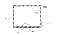
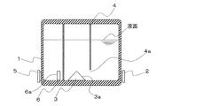
- FIG. 1 is a schematic view of a liquid container according to an embodiment of the present invention.
- the liquid container of the present invention includes a container main body 1 for storing liquid, an ultrasonic sensor 2 and a reflecting means 3.
- the container main body 1 is a cylindrical thing comprised by the top plate, the side wall, and the bottom plate.
- the shape of the container main body 1 used for this invention is not limited to this, What is necessary is just a shape which has the volume for storing a desired quantity of liquids.
- a conical shape, a prismatic shape, a pyramid shape, and the like can be mentioned.
- the shape of the container main body 1 is preferably a cylindrical shape.
- the raw material of the container main body 1 used for this invention is not specifically limited, When the liquid stored in the container main body 1 and a container contacts, the liquid stored in the container main body 1 and a container inside Anything that does not change quality is acceptable.
- the material of the container body 1 include glass, metal, plastic, stainless steel, and Teflon (registered trademark).
- the container In the case of containers used to store high-purity compounds used as raw materials for chemical vapor deposition, the container must have good cleanability, high strength, and little change in the liquid stored in the container. Therefore, stainless steel is particularly preferable.
- the ultrasonic sensor 2 is a sensor that detects and measures the presence / absence of an object and the distance to the object by transmitting the ultrasonic wave toward the object with a transmitter and receiving the reflected wave with a receiver. is there.
- the ultrasonic sensor 2 is attached to the container main body 1 in a state where it is in contact with the lowermost part of the outer surface of the side wall of the container main body 1.
- the ultrasonic wave from the ultrasonic sensor 2 is transmitted through the side wall into the liquid stored in the container body 1.
- the ultrasonic sensor 2 used in the present invention is not particularly limited, and a well-known general ultrasonic sensor can be used.
- the ultrasonic sensor 2 may be fixed to the outer surface of the side wall of the container body 1 or may be removable.
- the reflecting means 3 is a member having a reflecting surface 3 a inclined with respect to the vertical direction, and is attached to the upper surface of the bottom plate inside the container body 1.
- the shape of the reflecting means 3 used in the present invention may be, for example, a pyramid, a plate, a cube, a rectangular parallelepiped, a prism, or a combination of these shapes.
- the material of the reflecting means 3 used in the present invention is not particularly limited as long as it can reflect ultrasonic waves. Specifically, glass, metal, plastic, stainless steel, Teflon (registered) Trademark) and the like.
- the material of the reflecting means 3 may be the same as or different from the material used for the container body 1, but if the materials are different, there is a risk of liquid leakage from the joint or when cleaning the inside of the container It is preferable to use the same material as the container body 1 because there is a risk that the type of cleaning agent used for the container body 1 may be limited.
- the material of the reflecting means 3 alters the liquid stored in the container. Stainless steel is particularly preferable because it is rare.
- the reflecting means 3 may be integrated with the container body 1 or may be attached by a fixing member typified by welding, a screw, a screw or the like.
- the reflecting means 3 is arranged so that the ultrasonic sensor 2 and the reflecting surface 3a of the reflecting means 3 face each other.
- the inclination angle of the reflecting surface 3a is not particularly limited as long as the ultrasonic wave transmitted from the ultrasonic sensor 2 can be converted into the liquid surface direction.
- the ultrasonic wave transmitted from the ultrasonic sensor 2 into the liquid is reflected by the reflecting surface 3a of the reflecting means 3 toward the liquid surface of the liquid.
- the reflected wave further reflected by the liquid surface of the liquid is reflected again by the reflecting surface 3 a toward the ultrasonic sensor 2 and reaches the ultrasonic sensor 2.
- the ultrasonic sensor has a non-measurable area (dead zone). For this reason, if the distance from the ultrasonic sensor to the liquid level becomes smaller than the distance that becomes the dead zone, the liquid level cannot be measured.
- the reflecting means 3 is a position where the distance passing through the liquid in the ultrasonic path from the ultrasonic sensor 2 to the reflecting surface 3a of the reflecting means 3 is larger than the distance at which the ultrasonic sensor 2 becomes the dead zone. Is attached. Thereby, as long as the liquid level is higher than the reflection position of the ultrasonic wave on the reflection surface 3a, the liquid level can be measured in a short time without being affected by the dead zone of the ultrasonic sensor 2.
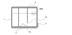
- FIG. 2 is a schematic view of a liquid container according to another embodiment of the present invention.
- the liquid container of the present invention includes a container body 1, an ultrasonic sensor 2, a reflecting means 3 and a guide means 4.
- the configurations of the container main body 1, the ultrasonic sensor 2, and the reflecting means 3 are the same as those in FIG.
- the guide means 4 has a cylindrical shape having a peripheral wall.
- the guide means 4 guides the ultrasonic wave reflected by the reflecting surface 3a of the reflecting means 3 toward the liquid surface of the liquid, and guides the reflected wave from the liquid surface toward the reflecting means 3. It is attached inside the main body 1.
- the guide means 4 may be integrated with the container main body 1 and the reflection means 3, and may be attached by fixing members represented by welding, screws, screws, or the like.
- the shape of the guide means 4 is not limited to this, and the ultrasonic wave reflected by the reflecting means 3 is guided toward the liquid surface of the liquid, and the reflected wave from the liquid surface is reflected by the reflecting means 3. Any shape can be used as long as it can be guided toward the vehicle. Examples of another shape of the guide means 4 include a rectangular tube shape and a plate shape. A cylindrical shape or a rectangular tube shape is preferable because it has a high effect of suppressing attenuation of ultrasonic waves.
- the material used for the guide means 4 is not particularly limited, but the liquid stored in the guide means 4 and the container body 1 is altered by the contact between the guide means 4 and the liquid stored in the container body 1. Any material may be used as long as it is not made to be the same as the container body 1.
- the guide means 4 has an opening 4a so that the ultrasonic wave transmitted from the ultrasonic sensor 2 can reach the reflection surface 3a of the reflection means 3.
- the opening 4 a is provided at the lowermost part of the peripheral wall of the guide means 4 in the direction in which the ultrasonic sensor 2 is installed.
- the shape and size of the opening 4a are not particularly limited, and the size and shape that allows the ultrasonic wave transmitted from the ultrasonic sensor 2 to pass through the opening 4a and reach the reflecting surface 3a of the reflecting means 3. If it is.
- the guide means 4 can also use the length which does not cover the reflective surface 3a of the reflection means 3, and in that case, it is not necessary to provide the opening part 4a.
- the ultrasonic wave transmitted from the ultrasonic sensor 2 into the liquid passes through the opening 4 a, is reflected by the reflecting surface 3 a of the reflecting means 3 toward the liquid surface of the liquid, and passes through the inner region of the peripheral wall of the guide means 4. And reaches the liquid level.
- the reflected wave further reflected by the liquid surface of the liquid passes through the inner region of the peripheral wall of the guide means 4 and is reflected again by the reflecting surface 3a toward the ultrasonic sensor 2, and passes through the opening 4a and becomes ultrasonic.
- the sensor 2 is reached.
- the fluidity of the liquid stored in the container body 1 may be improved by providing one or more holes penetrating the peripheral wall of the guide means 4 separately from the opening 4a.
- the position of the hole is not particularly limited, and may be any of an upper part, a middle part, and a lower part of the peripheral wall of the guide means 4.
- the shape of a hole is not specifically limited, A circular shape, polygonal shape, etc. are mentioned.
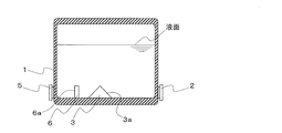
- FIG. 3 is a schematic view of a liquid container according to another embodiment of the present invention.
- the liquid container of the present invention comprises a container body 1, an ultrasonic sensor 2, a reflecting means 3, a calibration ultrasonic sensor 5, and a calibration reflecting means 6.
- the structure of the container main body 1, the ultrasonic sensor 2, and the reflection means 3 is the same as FIG. 1, description is abbreviate
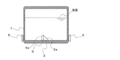
- FIG. 4 is a schematic view of a liquid container according to another embodiment of the present invention.
- the liquid container of the present invention comprises a container body 1, an ultrasonic sensor 2, a reflecting means 3, a calibration ultrasonic sensor 5, and a calibration reflecting means 6.
- the reflecting means 3 and the calibration reflecting means 6 are provided separately.
- the reflecting means 3 and the calibration reflecting means 6 are integrated. This is different from the liquid container shown in FIG.
- description is abbreviate
- the ultrasonic sensor 5 for calibration is attached to the container main body 1 in contact with the lowermost part of the outer surface of the side wall of the container main body 1.
- the calibration ultrasonic sensor 5 may be fixed to the outer surface of the side wall of the container body 1 or may be removable.
- the ultrasonic wave from the calibration ultrasonic sensor 5 is transmitted through the side wall into the liquid stored in the container body 1.
- the calibration ultrasonic sensor 5 is not particularly limited, and a well-known general ultrasonic sensor can be used.
- the calibration ultrasonic sensor 5 may be the same type of ultrasonic sensor as the ultrasonic sensor 2 or may be a different type of ultrasonic sensor.
- the calibration reflecting means 6 is a rectangular parallelepiped member having a reflecting surface 6a perpendicular to the bottom plate, and is attached to the upper surface of the bottom plate inside the container body 1 by a fixing member typified by welding, screws, screws or the like. ing.
- the shape of the calibration reflection means 6 is not limited to this, and may be, for example, a plate shape, a cube, a pyramid, a prism, or a combination of these shapes.
- the calibration reflecting means 6 may be integrated with the reflecting means 3 as shown in FIG.
- the calibration reflecting means 6 may be integrated with the container body 1 and the guide means 4.
- the material of the reflection means 6 for calibration is not particularly limited as long as it can reflect ultrasonic waves. Specifically, glass, metal, plastic, stainless steel, Teflon (registered trademark), etc. Is mentioned.
- the material of the reflection means 6 for calibration may be the same as or different from the material used for the container body 1, but if the materials are different, there is a risk of liquid leakage from the joint or cleaning the inside of the container. It is preferable to use the same material as the container body 1 because the type of cleaning agent used may be limited.
- the material of the calibration reflecting means 6 is a liquid stored in the container. Stainless steel is particularly preferred because it is rarely altered.
- the calibration reflection means 6 is arranged so that the reflection surface 6a of the calibration reflection means 6 and the calibration ultrasonic sensor 5 face each other. Further, as is well known, since the ultrasonic sensor has a non-measurable region (dead zone), the calibration reflecting means 6 is an ultrasonic path from the calibration ultrasonic sensor 5 to the reflecting surface 6 a of the calibration reflecting means 6. Is installed at a position where the distance that passes through the liquid becomes larger than the distance that becomes the dead zone of the calibration ultrasonic sensor 5. The ultrasonic wave transmitted from the calibration ultrasonic sensor 5 into the liquid is reflected by the reflection surface 6 a of the calibration reflection means 6 toward the calibration ultrasonic sensor 5 and reaches the calibration ultrasonic sensor 5.
- the speed of the ultrasonic wave transmitted through the liquid changes depending on the type of liquid stored in the container and the temperature of the liquid. If calibration values for conditions are not prepared, accurate values may not be measured. Therefore, by providing the calibration ultrasonic sensor 5 and the calibration reflecting means 6 as described above, ultrasonic waves under conditions such as the type of liquid stored in the container and the temperature of the liquid when the liquid level is measured are measured. Since a calibration value for sound velocity can be obtained, a more accurate value can be measured without preparing calibration values for various conditions in advance.
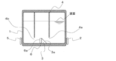
- FIG. 5 is a schematic view of a liquid container according to another embodiment of the present invention.
- the liquid container of the present invention comprises a container body 1, an ultrasonic sensor 2, a reflection means 3, a guide means 4, a calibration ultrasonic sensor 5 and a calibration reflection means 6.
- the configurations of the container main body 1, the ultrasonic sensor 2, the reflecting means 3, and the guide means 4 are the same as those in FIG. 2, and the configuration of the calibration ultrasonic sensor 5 is the same as that in FIG.
- the calibration reflecting means 6 is arranged in an external region of the peripheral wall of the guide means 3.
- the other configuration of the calibration reflecting means 6 is the same as that in FIG.
- FIG. 6 is a schematic view of a liquid container according to another embodiment of the present invention.
- the liquid container of the present invention comprises a container body 1, an ultrasonic sensor 2, a reflecting means 3, a guide means 4, a calibration ultrasonic sensor 5, and a calibration reflecting means 6.
- the calibration reflecting means 6 is integrated.
- the configurations of the container main body 1, the ultrasonic sensor 2, the reflecting means 3, the calibration ultrasonic sensor 5 and the calibration reflecting means 6 are the same as those in FIG.
- the guide unit 4 has an opening 4b so that the ultrasonic wave transmitted from the calibration ultrasonic sensor 5 can reach the reflection surface 6a of the calibration reflection unit 6.
- the opening 4 b is provided at the lowermost part of the peripheral wall of the guide means 4 in the direction in which the calibration ultrasonic sensor 5 is installed.
- the shape and size of the opening 4b are not particularly limited, and the ultrasonic wave transmitted from the calibration ultrasonic sensor 5 can pass through the opening 4b and reach the reflection surface 6a of the calibration reflecting means 6. Any size and shape may be used.
- the guide means 4 may be of a length that does not cover the reflection surface 6a of the calibration reflection means 6. In this case, it is not necessary to provide the opening 4b. Since the other structure of the guide means 4 is the same as FIG. 2, description is abbreviate
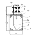
- FIG. 7 is a side cross-sectional view of a liquid container according to another embodiment of the present invention
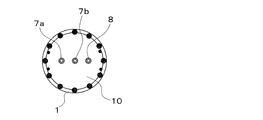
- FIG. 8 is a view of the liquid container shown in FIG. 7 as viewed from above.
- the liquid containers shown in FIGS. 7 and 8 are the same.
- the container for liquid of the present invention includes a container body 1, an ultrasonic sensor 2, a reflecting means 3, a first liquid transporting means 7a, a second liquid transporting means 7b, a gas transporting means 8, and a control mechanism. 9a, 9b, 9c and an opening / closing mechanism 10 are provided. Since the configurations of the container body 1, the ultrasonic sensor 2, and the reflection means 3 are the same as those in FIG. 3, the description thereof is omitted here.
- the first liquid transporting means 7a is a tubular one that penetrates the container body 1 and is attached to the container body 1 by a fixing member typified by welding, screws, screws, or the like.
- the shape of the first liquid transporting means 7a is not limited to this, and may be any shape that can transport the liquid.
- the end portion of the first liquid transporting means 7 a inserted into the container body 1 extends to the vicinity of the upper surface of the bottom plate inside the container body 1. By providing such first liquid transporting means 7a, the liquid can be introduced into the container body 1 or the stored liquid can be discharged out of the system.
- the second liquid transporting means 7b is a tubular one that penetrates the container body 1 and is attached to the container body 1 by a fixing member typified by welding, screws, screws, or the like.
- the shape of the second liquid transporting means 7b is not limited to this, and may be any shape that can transport the liquid.
- the end of the second liquid transporting means 7b inserted into the container main body 1 is located above the end of the first liquid transporting means 7a inserted into the container main body 1.
- the materials of the first liquid transporting means 7a and the second liquid transporting means 7b are not particularly limited, and the first liquid transporting means 7a, the second liquid transporting means 7b, and the liquid are not limited. Any material may be used as long as it does not change quality by contact, but the same material as that of the container body 1 is preferably used.
- the first liquid transporting means 7a and the second liquid transporting means 7b are arranged such that the first liquid transporting means 7a and the second liquid transporting means 7b are not obstructed by the ultrasonic waves transmitted from the ultrasonic sensor 2 into the liquid.
- the part inserted into the container main body 1 of the second liquid transporting means 7b is installed so as not to exist on the ultrasonic path.
- the gas transport means 8 is a tubular member that penetrates the container main body 1 and is attached to the container main body 1 by a fixing member represented by welding, screws, screws, or the like.
- the gas transport means 8 is not limited to this, and may be any shape that can transport gas.
- the gas transporting means 8 is configured such that the portion of the gas transporting means 8 inserted into the container main body 1 does not come into contact with the liquid stored in the container main body 1 when the container is left standing. The part is installed so as to be above the liquid level of the liquid.
- the gas transport means 8 may be one having a function of evacuating the inside of the container main body 1 (exhaust means), or may be one having a function of injecting gas into the container main body 1.
- the gas transporting means 8 When the gas transporting means 8 has a function of evacuating the inside of the container main body 1, it is suitable as a container for chemical vapor deposition raw materials used for semiconductor manufacturing or the like.
- the medium through which the ultrasonic wave is transmitted is a liquid, so that the liquid level can be correctly measured even when the container body 1 is in a vacuum state.
- the liquid can be easily discharged out of the system from the first liquid transport means 7a or the second liquid transport means 7b. .
- the material for the gas transport means 8 is not particularly limited as long as the gas transport means 8 and the transported gas come into contact with each other as long as they do not change in quality. It is preferable to use a material.
- the first liquid transporting means 7a, the second liquid transporting means 7b, and the gas transporting means 8 have control mechanisms 9a, 9b, 9c represented by valves, respectively, outside the container body 1.
- the valve is not particularly limited, and a commonly used valve may be used. Examples thereof include a gate valve, a ball valve, and a diaphragm valve.
- the opening / closing mechanism 10 is a lid provided on the top plate of the container body 1.
- the opening / closing mechanism 10 has a disk shape, and may be fixed to the container body 1 by a fixing member represented by a screw, a screw, or the like, or may be detachable.
- the shape of the opening / closing mechanism 10 is not limited to this.
- the material of the opening / closing mechanism 10 is not particularly limited as long as the opening / closing mechanism 10 and the liquid in the container main body 1 or the vapor generated therefrom are brought into contact with each other. It is preferable to use the same material.
- the top plate, the side wall, and the bottom plate of the container body 1 are provided with coupling means so that the liquid container itself is fixed to a stand or the pipe connected to the liquid container is fixed. Also good.
- the coupling means include fixing members represented by screws, screws and the like.
- the liquid level of the liquid stored in the liquid container measures the time from when an ultrasonic wave is transmitted from the ultrasonic sensor until it is received, converts the measurement time into a distance, It can be obtained by subtracting the distance passing through the liquid in the ultrasonic path from the ultrasonic sensor to the reflecting surface of the reflecting means from the distance.
- the liquid container of the present invention can measure the liquid level in a short time without being affected by the dead zone of the ultrasonic sensor even when the liquid level is low.
- the liquid container provided with the guide means of the present invention has an influence on the measurement even when bubbles are generated in the liquid stored in the container due to heating, vibration or the like when measuring the liquid level. Since it can be reduced and ultrasonic wave diffusion is prevented and attenuation of the ultrasonic wave can be suppressed, the liquid level can be measured with high accuracy.
- the liquid container provided with the calibration ultrasonic sensor and the calibration reflecting means of the present invention can measure the liquid level with high accuracy without preparing calibration values under various conditions in advance.
- the container for liquid provided with the exhaust means of this invention can be used conveniently for storing the high purity compound used as a chemical vapor deposition raw material.
- Example 1 The liquid level was measured using the liquid container of the present invention.
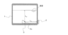
- the form of the liquid container used in Example 1 is shown in FIG.
- L 1 represents the distance that the ultrasonic wave passes through the liquid in the ultrasonic path from the ultrasonic sensor 2 to the reflective surface 3 a of the reflecting means 3
- L 2 represents the liquid surface from the reflecting surface 3 a of the reflecting means 3.
- L 1 60 mm
- L 1 + L 2 20 mm
- L 1 is constant, the liquid level can be calculated by subtracting the L 1 from L 1 + L 2.
- the dead zone of this ultrasonic sensor is 30 mm. The results are shown in Table 1.
- Example 1 From the results of Example 1, it can be seen that according to the present invention, the liquid level can be accurately measured even when the liquid level of the liquid stored in the container is lower than the dead zone of the ultrasonic sensor. .
- Container body 1. Ultrasonic sensor, 3. Reflection means, 3a reflection surface, 4. Guide means, 4a, 4b opening, 5. Calibration ultrasonic sensor, 6. Calibration reflection means, 6a reflection surface, 7a.
- First liquid transport Means, 7b second liquid transport means, 8 gas transport means, 9a, 9b, 9c control mechanism, 10 opening / closing mechanism.
Abstract
Description
即ち、本発明は、液体を貯留する容器本体と、該容器本体の外側壁に当接し且つ超音波が該液体中に発信されるように設置された超音波センサと、該容器本体の内底部に設置され且つ超音波センサから該液体中に発信された超音波を該液体の液面に向けて反射する反射手段とを備え、該反射手段は、該超音波センサから該反射手段の反射面までの超音波経路のうち該液体中を通過する距離が該超音波センサの不感帯となる距離よりも大きくなる位置に設置されている液体用容器である。
図1は、本発明の実施形態に係る液体用容器の概要図である。同図において、本発明の液体用容器は、液体を貯留する容器本体1、超音波センサ2及び反射手段3を備えている。容器本体1は、天板、側壁及び底板で構成された円筒状のものである。なお、本発明に用いられる容器本体1の形状は、これに限定されるものではなく、所望の量の液体を貯留するための容積を有する形状であればよい。容器本体1の別の形状としては、例えば、円錐状、角柱状、角錐状等が挙げられるが、洗浄の容易さを考慮すると、容器本体1の形状は、円筒状であることが好ましい。
なお、第1の液体輸送用手段7a及び第2の液体輸送用手段7bは、超音波センサ2から液体中に発信された超音波の障害とならないよう、第1の液体輸送用手段7a及び第2の液体輸送用手段7bの容器本体1内に挿入された部分が超音波経路上に存在しないように設置されている。
本発明の液体用容器を用いて液面レベルを測定した。実施例1で用いた液体用容器の形態を図9に示す。ここで、L1は超音波センサ2から反射手段3の反射面3aまでの超音波経路のうち超音波が液体中を通過する距離を表し、L2は反射手段3の反射面3aから液面までの距離を表す。L1=60mm、L2=20mmとしてL1+L2を測定した。L1は一定であることから、液面レベルはL1+L2からL1を減算することで算出することができる。なお、この超音波センサの不感帯は30mmである。結果を表1に示す。
超音波センサを容器本体の外底部に設置した液体用容器を用いて、液面レベルを測定した。比較例1で用いた液体用容器の形態を図10に示す。ここで、L3は超音波センサ2から液面までの超音波経路のうち超音波が液中を通過する距離を表す。L3=20mmとして測定した。なお、この超音波センサの不感帯は30mmである。結果を表1に示す。

Claims (5)
- 液体を貯留する容器本体と、
該容器本体の外側壁に当接し且つ超音波が該液体中に発信されるように設置された超音波センサと、
該容器本体の内底部に設置され且つ超音波センサから該液体中に発信された超音波を該液体の液面に向けて反射する反射手段と
を備え、
該反射手段は、該超音波センサから該反射手段の反射面までの超音波経路のうち該液体中を通過する距離が該超音波センサの不感帯となる距離よりも大きくなる位置に設置されている液体用容器。 - 前記反射手段で反射された超音波を前記液体の液面に向けて案内すると共に、その液面からの反射波を前記反射手段に向けて案内するためのガイド手段を更に備える請求項1に記載の液体用容器。
- 前記容器本体の外側壁に当接し且つ超音波が前記液体中に発信されるように設置された校正用超音波センサと、
前記容器本体の内底部に設置され且つ該校正用超音波センサから前記液体中に発信された超音波を該校正用超音波センサに向けて反射する校正用反射手段と
を更に備える請求項1又は2に記載の液体用容器。 - 前記容器本体内を真空排気するための排気手段を更に備える請求項1~3のいずれか一項に記載の液体用容器。
- 請求項1~4のいずれか1項に記載の液体用容器に貯留された液体の液面レベルを測定する方法であって、前記超音波センサから超音波が発信されてから受信するまでの時間を計測し、その計測時間を距離に換算し、その距離から、前記超音波センサから前記反射手段の反射面までの超音波経路のうち前記液体中を通過する距離を減算することを含む、液面レベルの測定方法。
Priority Applications (4)
| Application Number | Priority Date | Filing Date | Title |
|---|---|---|---|
| KR1020157004079A KR102000329B1 (ko) | 2012-08-13 | 2013-07-29 | 액체용 용기 및 이것을 사용한 액면 레벨의 측정 방법 |
| DE112013004042.5T DE112013004042T5 (de) | 2012-08-13 | 2013-07-29 | Flüssigkeitsbehälter und Verfahren zur Messung des Flüssigkeitsspiegels unter Verwendung desselben |
| US14/419,331 US9605990B2 (en) | 2012-08-13 | 2013-07-29 | Liquid container and method for measuring liquid level using same |
| CN201380043021.5A CN104583736A (zh) | 2012-08-13 | 2013-07-29 | 液体用容器和使用该液体用容器的液面高度的测量方法 |
Applications Claiming Priority (2)
| Application Number | Priority Date | Filing Date | Title |
|---|---|---|---|
| JP2012179357A JP5814886B2 (ja) | 2012-08-13 | 2012-08-13 | 液体用容器及びこれを用いた液面レベルの測定方法 |
| JP2012-179357 | 2012-08-13 |
Publications (1)
| Publication Number | Publication Date |
|---|---|
| WO2014027561A1 true WO2014027561A1 (ja) | 2014-02-20 |
Family
ID=50286249
Family Applications (1)
| Application Number | Title | Priority Date | Filing Date |
|---|---|---|---|
| PCT/JP2013/070486 WO2014027561A1 (ja) | 2012-08-13 | 2013-07-29 | 液体用容器及びこれを用いた液面レベルの測定方法 |
Country Status (7)
| Country | Link |
|---|---|
| US (1) | US9605990B2 (ja) |
| JP (1) | JP5814886B2 (ja) |
| KR (1) | KR102000329B1 (ja) |
| CN (1) | CN104583736A (ja) |
| DE (1) | DE112013004042T5 (ja) |
| TW (1) | TWI592640B (ja) |
| WO (1) | WO2014027561A1 (ja) |
Cited By (2)
| Publication number | Priority date | Publication date | Assignee | Title |
|---|---|---|---|---|
| WO2016101202A1 (en) * | 2014-12-25 | 2016-06-30 | Fontem Holdings 2 B.V. | Electronic cigarette liquid detection and measurement systems |
| US20160216148A1 (en) * | 2013-09-27 | 2016-07-28 | Continental Automotive Gmbh | Liquid Tank With An Ultrasonic Sensor |
Families Citing this family (12)
| Publication number | Priority date | Publication date | Assignee | Title |
|---|---|---|---|---|
| CN103201600B (zh) * | 2010-11-11 | 2015-05-20 | Ssi技术公司 | 确定柴油机排气流体的质量和/或深度的系统和方法 |
| DE102012212210A1 (de) * | 2012-07-12 | 2014-01-16 | Continental Automotive Gmbh | Verfahren und Vorrichtung zum Bestimmen einer Höhe eines Fluidniveaus in einem Fluidbehälter |
| DE102014210080A1 (de) * | 2014-05-27 | 2015-12-03 | Continental Automotive Gmbh | Vorrichtung zum Bestimmen einer Höhe einer Fluidoberfläche in einem Fluidbehälter |
| DE102014210077A1 (de) | 2014-05-27 | 2015-12-03 | Continental Automotive Gmbh | Vorrichtung und Verfahren zum Bestimmen einer Höhe einer Fluidoberfläche in einem Fluidbehälter |
| DE102014213233A1 (de) * | 2014-07-08 | 2016-01-14 | Continental Automotive Gmbh | Vorrichtung zum Bestimmung einer Schallgeschwindigkeit eines Schallsignals in einem Fluid |
| ES2648541B1 (es) * | 2016-07-01 | 2018-10-10 | Serviglp, S.L. | Monitorización del nivel de un producto en un contenedor |
| WO2019020151A1 (en) * | 2017-07-27 | 2019-01-31 | Odin & Thor Aps | ELECTRONIC SMOKING SYSTEM |
| CN110501055A (zh) * | 2018-05-16 | 2019-11-26 | 国网福建省电力有限公司漳州供电公司 | 基于超声探测的变压器油枕油位的测量方法 |
| CN111938450B (zh) * | 2019-05-15 | 2023-08-22 | 广东美的生活电器制造有限公司 | 上盖组件及加热容器 |
| CN110146894A (zh) * | 2019-05-19 | 2019-08-20 | 瑞立集团瑞安汽车零部件有限公司 | 基于气囊内超声波测距的汽车高度传感器 |
| TWI708045B (zh) * | 2019-06-28 | 2020-10-21 | 黃智淵 | 桶裝物料的配送系統及其操作方法 |
| CN113432674B (zh) * | 2021-06-30 | 2023-09-26 | 杭州艾科赛德电子科技有限公司 | 一种基于声呐的容器液位探测系统 |
Citations (1)
| Publication number | Priority date | Publication date | Assignee | Title |
|---|---|---|---|---|
| JP4120560B2 (ja) * | 2003-10-24 | 2008-07-16 | 株式会社デンソー | 車両用液面検出装置 |
Family Cites Families (15)
| Publication number | Priority date | Publication date | Assignee | Title |
|---|---|---|---|---|
| JPH04120560A (ja) | 1990-09-11 | 1992-04-21 | Minolta Camera Co Ltd | 作像装置 |
| JP2000121410A (ja) | 1998-10-13 | 2000-04-28 | Toyota Motor Corp | 液面レベル検出装置 |
| JP4248078B2 (ja) | 1999-04-30 | 2009-04-02 | リコーエレメックス株式会社 | 液面レベル検出方法および装置 |
| EP1176403A3 (en) * | 2000-07-28 | 2003-03-19 | Seiko Epson Corporation | Detector of liquid consumption condition |
| US7117738B2 (en) * | 2003-10-02 | 2006-10-10 | Denso Corporation | Liquid level detecting apparatus |
| US7542870B2 (en) * | 2006-02-28 | 2009-06-02 | Ssi Technologies, Inc. | Immersed fuel level sensor |
| JP5024686B2 (ja) | 2006-07-18 | 2012-09-12 | コンティ テミック マイクロエレクトロニック ゲゼルシャフト ミット ベシュレンクテル ハフツング | 液体レベルを求めるための多室超音波センサ |
| WO2008101339A1 (en) * | 2007-02-21 | 2008-08-28 | Sensotech Inc. | Fluid level measuring method and system therefor |
| DE102008029771A1 (de) * | 2008-06-25 | 2009-12-31 | Endress + Hauser Gmbh + Co. Kg | Anordnung zur Füllstandsmessung |
| CN101723373B (zh) * | 2008-10-23 | 2011-12-14 | 北京有色金属研究总院 | 一种带有氮气保护的三氯氢硅或四氯化硅工艺系统的控制管路 |
| US20110232381A1 (en) * | 2010-03-25 | 2011-09-29 | Al-Absi Munir A | System for monitoring liquid level in underground storage tank |
| US8583387B2 (en) * | 2010-06-04 | 2013-11-12 | Ssi Technologies, Inc. | Ultrasonic level, on-board diagnostic assessment |
| DE102010023742A1 (de) * | 2010-06-14 | 2011-12-15 | Fafnir Gmbh | Verfahren und Vorrichtung zum Erfassen von Flüssigkeit in einer Gasrückführungsleitung |
| CN103201600B (zh) * | 2010-11-11 | 2015-05-20 | Ssi技术公司 | 确定柴油机排气流体的质量和/或深度的系统和方法 |
| CN102275697B (zh) * | 2011-04-20 | 2013-01-02 | 长沙汇一制药机械有限公司 | 一种能在线清洗和消毒的压力平衡罐 |
-
2012
- 2012-08-13 JP JP2012179357A patent/JP5814886B2/ja active Active
-
2013
- 2013-07-29 DE DE112013004042.5T patent/DE112013004042T5/de not_active Withdrawn
- 2013-07-29 KR KR1020157004079A patent/KR102000329B1/ko active IP Right Grant
- 2013-07-29 US US14/419,331 patent/US9605990B2/en active Active
- 2013-07-29 WO PCT/JP2013/070486 patent/WO2014027561A1/ja active Application Filing
- 2013-07-29 CN CN201380043021.5A patent/CN104583736A/zh active Pending
- 2013-08-07 TW TW102128292A patent/TWI592640B/zh active
Patent Citations (1)
| Publication number | Priority date | Publication date | Assignee | Title |
|---|---|---|---|---|
| JP4120560B2 (ja) * | 2003-10-24 | 2008-07-16 | 株式会社デンソー | 車両用液面検出装置 |
Cited By (4)
| Publication number | Priority date | Publication date | Assignee | Title |
|---|---|---|---|---|
| US20160216148A1 (en) * | 2013-09-27 | 2016-07-28 | Continental Automotive Gmbh | Liquid Tank With An Ultrasonic Sensor |
| US9885597B2 (en) * | 2013-09-27 | 2018-02-06 | Continental Automotive Gmbh | Liquid tank with an ultrasonic sensor |
| WO2016101202A1 (en) * | 2014-12-25 | 2016-06-30 | Fontem Holdings 2 B.V. | Electronic cigarette liquid detection and measurement systems |
| US10736357B2 (en) | 2014-12-25 | 2020-08-11 | Fontem Holdings 1 B.V. | Electronic cigarette liquid detection and measurement systems |
Also Published As
| Publication number | Publication date |
|---|---|
| US20150185065A1 (en) | 2015-07-02 |
| TW201425882A (zh) | 2014-07-01 |
| KR20150040934A (ko) | 2015-04-15 |
| DE112013004042T5 (de) | 2015-05-07 |
| US9605990B2 (en) | 2017-03-28 |
| TWI592640B (zh) | 2017-07-21 |
| JP2014037994A (ja) | 2014-02-27 |
| JP5814886B2 (ja) | 2015-11-17 |
| CN104583736A (zh) | 2015-04-29 |
| KR102000329B1 (ko) | 2019-07-15 |
Similar Documents
| Publication | Publication Date | Title |
|---|---|---|
| JP5814886B2 (ja) | 液体用容器及びこれを用いた液面レベルの測定方法 | |
| CN106338332B (zh) | 用于测量液体或气态介质中的声音速度的系统和方法 | |
| US10228275B2 (en) | System and method for non-intrusive and continuous level measurement in a cylindrical vessel | |
| CN106338320B (zh) | 用于液体的非侵入性连续液位测量的系统和方法 | |
| US20100018309A1 (en) | Fluid level measuring method and system therefor | |
| US20160320226A1 (en) | Determining height of a liquid level interface in a container from acoustic signal or echo time measurement | |
| US20190078927A1 (en) | Sensor | |
| US20170292870A1 (en) | Ultrasonic level sensor with reflectors | |
| JP6826097B2 (ja) | 液体レベルのガス組成及び温度が補償された音響測定を提供するための装置 | |
| US20120079890A1 (en) | Measuring device and method for measuring a measured variable | |
| US8180582B2 (en) | System and method for sensing liquid levels | |
| TWI413769B (zh) | 偵測流體的系統 | |
| US6990046B2 (en) | Sonar transducer | |
| KR20160056872A (ko) | 액체 레벨의 가스 조성 및 온도 보상형 음향 측정 장치 | |
| CN106482809B (zh) | 用于确定容器内液体高度的方法和装置 | |
| JP2004340911A (ja) | 車両用液面検出装置 | |
| WO2006134358A1 (en) | Acoustic wave sensor for sensing fluid level | |
| CN112798465A (zh) | 用于确定容器中的液体性质的测量系统 | |
| US20230417590A1 (en) | Hygienic guided wave level measurement with sheath | |
| MacIntosh et al. | Noninvasive noncontact fluid detection in submerged containers using swept frequency ultrasonic technique | |
| CN117906690A (zh) | 超声波流量计 | |
| JP2000046631A (ja) | 超音波による液面レベル測定装置 | |
| FI71839B (fi) | Vaetskenivaokaenselorgan | |
| JP2020098129A (ja) | 超音波レベル計用の導波管 | |
| JP2008151667A (ja) | 測距センサ及びそれを備えた設備機器 |
Legal Events
| Date | Code | Title | Description |
|---|---|---|---|
| 121 | Ep: the epo has been informed by wipo that ep was designated in this application |
Ref document number: 13879432 Country of ref document: EP Kind code of ref document: A1 |
|
| WWE | Wipo information: entry into national phase |
Ref document number: 14419331 Country of ref document: US |
|
| WWE | Wipo information: entry into national phase |
Ref document number: 112013004042 Country of ref document: DE Ref document number: 1120130040425 Country of ref document: DE |
|
| ENP | Entry into the national phase |
Ref document number: 20157004079 Country of ref document: KR Kind code of ref document: A |
|
| 122 | Ep: pct application non-entry in european phase |
Ref document number: 13879432 Country of ref document: EP Kind code of ref document: A1 |