WO2014024817A1 - バグフィルター用空気増幅装置および該バグフィルター用空気増幅装置を用いたバグフィルター用空気増幅システム - Google Patents
バグフィルター用空気増幅装置および該バグフィルター用空気増幅装置を用いたバグフィルター用空気増幅システム Download PDFInfo
- Publication number
- WO2014024817A1 WO2014024817A1 PCT/JP2013/071106 JP2013071106W WO2014024817A1 WO 2014024817 A1 WO2014024817 A1 WO 2014024817A1 JP 2013071106 W JP2013071106 W JP 2013071106W WO 2014024817 A1 WO2014024817 A1 WO 2014024817A1
- Authority
- WO
- WIPO (PCT)
- Prior art keywords
- air
- compressed air
- bag filter
- compressed
- introduction
- Prior art date
- Legal status (The legal status is an assumption and is not a legal conclusion. Google has not performed a legal analysis and makes no representation as to the accuracy of the status listed.)
- Ceased
Links
Images





Classifications
-
- B—PERFORMING OPERATIONS; TRANSPORTING
- B01—PHYSICAL OR CHEMICAL PROCESSES OR APPARATUS IN GENERAL
- B01D—SEPARATION
- B01D46/00—Filters or filtering processes specially modified for separating dispersed particles from gases or vapours
- B01D46/02—Particle separators, e.g. dust precipitators, having hollow filters made of flexible material
- B01D46/04—Cleaning filters
-
- B—PERFORMING OPERATIONS; TRANSPORTING
- B01—PHYSICAL OR CHEMICAL PROCESSES OR APPARATUS IN GENERAL
- B01D—SEPARATION
- B01D46/00—Filters or filtering processes specially modified for separating dispersed particles from gases or vapours
- B01D46/66—Regeneration of the filtering material or filter elements inside the filter
- B01D46/70—Regeneration of the filtering material or filter elements inside the filter by acting counter-currently on the filtering surface, e.g. by flushing on the non-cake side of the filter
- B01D46/71—Regeneration of the filtering material or filter elements inside the filter by acting counter-currently on the filtering surface, e.g. by flushing on the non-cake side of the filter with pressurised gas, e.g. pulsed air
-
- F—MECHANICAL ENGINEERING; LIGHTING; HEATING; WEAPONS; BLASTING
- F04—POSITIVE - DISPLACEMENT MACHINES FOR LIQUIDS; PUMPS FOR LIQUIDS OR ELASTIC FLUIDS
- F04F—PUMPING OF FLUID BY DIRECT CONTACT OF ANOTHER FLUID OR BY USING INERTIA OF FLUID TO BE PUMPED; SIPHONS
- F04F5/00—Jet pumps, i.e. devices in which flow is induced by pressure drop caused by velocity of another fluid flow
- F04F5/14—Jet pumps, i.e. devices in which flow is induced by pressure drop caused by velocity of another fluid flow the inducing fluid being elastic fluid
- F04F5/16—Jet pumps, i.e. devices in which flow is induced by pressure drop caused by velocity of another fluid flow the inducing fluid being elastic fluid displacing elastic fluids
- F04F5/20—Jet pumps, i.e. devices in which flow is induced by pressure drop caused by velocity of another fluid flow the inducing fluid being elastic fluid displacing elastic fluids for evacuating
-
- F—MECHANICAL ENGINEERING; LIGHTING; HEATING; WEAPONS; BLASTING
- F04—POSITIVE - DISPLACEMENT MACHINES FOR LIQUIDS; PUMPS FOR LIQUIDS OR ELASTIC FLUIDS
- F04F—PUMPING OF FLUID BY DIRECT CONTACT OF ANOTHER FLUID OR BY USING INERTIA OF FLUID TO BE PUMPED; SIPHONS
- F04F5/00—Jet pumps, i.e. devices in which flow is induced by pressure drop caused by velocity of another fluid flow
- F04F5/44—Component parts, details, or accessories not provided for in, or of interest apart from, groups F04F5/02 - F04F5/42
- F04F5/46—Arrangements of nozzles
Definitions
- the present invention relates to an air amplifier for a bag filter. More specifically, the present invention relates to a bag filter air amplifying device used for bag filter backwashing and a bag filter air amplifying system using the bag filter air amplifying device.
- bag filters filter cloth type dust collectors
- a bag filter is one of filtration dust collectors, and is a device that uses a woven fabric or a nonwoven fabric as a filter medium and makes it cylindrical to remove dust or collect powder.
- Patent Document 1 includes a cleaning circuit that selectively connects a dust-containing air chamber and a purified air chamber.
- the circuit includes a toxic gas removing member, a heater, and a hot air circulation fan, and purified air.
- a filter cloth type dust collector that allows an operator to enter and allows the filter cloth to be taken out easily.
- the filter cloth type dust collector of Patent Document 1 includes a reverse injection pipe that feeds compressed air (reference numeral 12 in FIG. 1 of Patent Document 1) and a nozzle that injects compressed air (reference numeral 13 in FIG. 1 of Patent Document 1). It is designed so that backwashing can be performed.
- the compressed air injected from the nozzle uses a venturi, it flows while spreading toward the side of the filter, so there is also the problem of damaging the side of the filter by repeating backwashing many times. there were. Further, when a long filter is used, there is a problem that the compressed air does not reach the bottom surface of the filter, and the backwashing effect is lowered at the lower part of the filter. In addition, since the venturi is attached, the intake air flow path is narrowed by the throttle portion, and there is a problem that air resistance increases and pressure loss occurs when backwashing is not performed.
- bag filters have been backwashed using an air amplifying device having a Coanda effect. Since air for backwashing is jetted from the air amplifying device having the Coanda effect almost parallel to the side of the filter, dust and powder adhering to the filter can be removed without damaging the side of the filter. Can do.
- Patent Document 2 discloses a Coanda injector in which an inlet for pressurized air and an inlet for external air are arranged on the same plane in order to reduce pressure loss due to a change in the path of pressurized air. ing.
- Patent Document 3 a pipe for supplying compressed air is divided into two branch pipes, and an air amplifier is connected to the upper part of the branch pipe, and the peripheral equipment is obstructed by the air pressure amplified from the air amplifier.
- a compressed air injection device using an air amplifier that can uniformly supply a larger amount of ambient air to a bag filter at a higher speed so as to exhibit a high dust removal effect.
- the main object of the present invention is to provide an air amplifying device excellent in air amplifying efficiency and suitable for backwashing a bag filter.
- the present inventor has conducted intensive research on the specific structure of the air amplifying device for improving the air amplifying efficiency, and as a result, has determined that the injection direction of the compressed air is important.
- the present invention has been completed.
- an air amplifier used for backwashing a bag filter An R-shaped inclined surface that spreads outward, an external air induction port that is connected to the R-shaped inclined surface to attract external air, an amplified air discharge port that discharges amplified air, and the external air attraction
- An air amplifying part provided with a cylindrical side wall provided from the mouth to the amplified air discharge port; Compressed air introduction port for introducing compressed air, compressed air injection hole for injecting compressed air to the air amplifying unit, and a curve for guiding the compressed air introduced from the compressed air introduction port to the compressed air injection hole
- a compressed air introduction part provided with a compressed air guide wall, Comprising at least The compressed air injection hole provides a bag filter air amplifying device provided in the external air inlet along the R-shaped inclined surface.
- the injection angle of the compressed air to the air amplifying unit is smaller than 90 ° along the R-shaped inclined surface. It is injected at an angle.
- the R-shaped inclined surface is formed by the compressed air guiding wall. Design in a covered state. Moreover, it is preferable to design so that the center of the compressed air introduction port is located outside the apex of the curve of the compressed air guide wall. Furthermore, it is preferable that the cross-sectional area of the amplified air discharge port is designed wider than the cross-sectional area of the external air induction port.
- the side wall is expanded outward, thereby reducing the cross-sectional area of the amplified air discharge port of the external air induction port. It is preferable to design wider than the cross-sectional area.
- the compressed air injection hole may be formed by a gap between the compressed air guide wall and the R-shaped inclined surface. At this time, it is preferable that a convex portion is formed on the inner wall surface of the compressed air guide wall toward the R-shaped inclined surface. It is more preferable that the convex portion is provided along the flow direction of the compressed air.
- the bag filter air amplifying device according to the present invention described above is suitable as an air amplifying system used for backwashing a bag filter by adding a compressed air introduction pipe for introducing compressed air to the compressed air introducing portion of the air amplifying device.
- the bag filter air amplification system according to the present invention is not particularly limited as long as it has the bag filter air amplification device according to the present invention. It is preferable that the connection surface and the connection surface between the compressed air introduction part of the compressed air introduction pipe are formed in parallel to each other. Moreover, it is preferable that the connection part of the said compressed air introduction part and the said compressed air introduction pipe
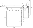
- FIG. 1 is a schematic perspective view schematically showing a first embodiment of a bag filter air amplifying device 1 according to the present invention. It is the cross-sectional schematic diagram which looked at 1st Embodiment of the air amplifier for bag filters 1 concerning this invention from the side surface. It is the cross-sectional schematic diagram which looked at 2nd Embodiment of the air amplifier for bag filters 1 concerning this invention from the side surface. It is the expanded cross-sectional schematic diagram which expanded the broken-line circle
- FIG. 1 is a schematic perspective view schematically showing a first embodiment of an air amplifying device 1 for a bag filter according to the present invention.
- FIG. 2 is a schematic cross-sectional view of the first embodiment of the bag filter air amplifying device 1 according to the present invention as viewed from the side.
- the bag filter air amplifying device 1 is roughly divided into at least an air amplifying unit 11 and a compressed air introducing unit 12.
- the air amplifying unit 11 includes an R-shaped inclined surface 111, an external air attracting port 112, an amplified air discharge port 113, and a side wall 114.
- the compressed air introducing unit 12 includes a compressed air introducing port 121, A compressed air injection hole 122 and a compressed air guide wall 123 are provided.
- each part will be described in detail.
- Air amplifier 11 The air amplifying unit 11 is a part that amplifies air using the Coanda effect by the compressed air injected from the compressed air introducing unit 12 described later.
- the R-shaped inclined surface 111 takes a form of expanding outward in order to guide the external air to the external air inlet 112 described later.
- Specific aspects such as the size and inclination angle of the R-shaped inclined surface 111 are not particularly limited as long as the effects of the present invention are not impaired, and can be freely designed according to the target bag filter or the like.
- the external air induction port 112 is connected to the R-shaped inclined surface 111 and is a part that attracts external air.
- the opening area and the opening shape of the external air inlet 112 are not particularly limited as long as the effects of the present invention are not impaired, and can be freely designed according to the size of the filter cloth used for the target bag filter. As an example, for example, when the diameter of the filter cloth of the bag filter is about 150 mm, the external air inlet 112 can be designed with an inner diameter of 70 to 80 mm.
- the amplified air discharge port 113 is a portion that discharges the amplified air toward the bag filter.
- the opening area and opening shape of the amplified air discharge port 113 are not particularly limited as long as the effects of the present invention are not impaired, and can be freely designed according to the size of the filter cloth used for the target bag filter. For example, when the diameter of the filter cloth of the bag filter is about 150 mm, the amplified air discharge port 113 can be designed with an inner diameter of 70 to 80 mm.
- the external air inlet 112 and the amplified air outlet 113 are designed to have the same opening area and shape (see, for example, Patent Document 3 FIG. 3).
- the external air inlet 112 and the amplified air outlet 113 can be designed to have the same opening area and opening shape as in the prior art.
- the inventor of the present application has found that the air amplification efficiency is further improved by designing the cross-sectional area of the amplified air discharge port 113 wider than the cross-sectional area of the external air induction port 112.
- the cross-sectional area of the amplified air discharge port 113 As a method for designing the cross-sectional area of the amplified air discharge port 113 to be wider than the cross-sectional area of the external air induction port 112, there is a method of expanding a predetermined portion of the side wall 114 described later outward. At this time, it is preferable to widen the side wall 114 outward at a portion where the Coanda effect by the compressed air injected from the compressed air injection hole 122 is at least maintained (see W in FIG. 3).
- the air amplification efficiency can be reliably improved by spreading the side wall 114 outward at a portion where the Coanda effect is maintained at least.
- the side wall 114 is provided from the external air induction port 112 to the amplified air discharge port 113, and includes external air attracted from the external air induction port 112 and compressed air injected from a compressed air injection hole 122 described later. In order to guide to the amplified air outlet 113, it has a cylindrical shape. Specific aspects such as the length of the side wall 114 are not particularly limited as long as the effects of the present invention are not impaired, and can be freely designed in accordance with the target bag filter or the like.
- the compressed air introduction part 12 is a part for introducing the compressed air sent from the compressed air introduction pipe 2 to be described later into the bag filter air amplifying apparatus 1 according to the present invention.
- the compressed air introduction port 121 is a part for introducing the compressed air sent from the compressed air introduction pipe 2 described later into the compressed air introduction unit 12.
- the specific aspects such as the opening area and the opening shape of the compressed air inlet 121 are not particularly limited as long as the effects of the present invention are not impaired, and can be freely selected according to the target bag filter or the form of the compressed air inlet pipe 2 to be connected. Can be designed to
- the compressed air injection hole 122 is a part for injecting the compressed air introduced from the compressed air introduction port 121 to the air amplifying unit 11.
- the bag filter air amplifying device 1 according to the present invention is characterized in that the compressed air injection hole 122 is provided in the external air inlet 112 along the R-shaped inclined surface 111.
- the compressed air injection hole is provided outside the R-shaped inclined surface. That is, when injecting compressed air to the air amplifying unit in order to generate the Coanda effect, it has been common knowledge that the injection angle from the compressed air inlet is designed to be perpendicular to the direction in which external air is attracted (for example, Patent Document 3 FIG. 3 code (3), specification paragraph number 0022). However, the idea is changed from the common sense in the prior art, and in the air amplifying device 1 for bag filter according to the present invention, the compressed air injection hole 122 is provided in the external air inlet 112 along the R-shaped inclined surface 111. It is characterized by that.
- the injection angle of the compressed air from the compressed air introduction port 121 to the air amplifying unit 11 is injected along the R-shaped inclined surface 111 at an angle smaller than 90 ° with respect to the attracting direction of the external air. It is characterized by.
- the injection angle of the compressed air from the compressed air introduction port 121 to the air amplifying unit 11 is injected along the R-shaped inclined surface 111 at an angle smaller than 90 ° with respect to the direction in which the external air is attracted.
- the compressed air injection hole 122 can be formed by a gap between a compressed air guide wall 123 described later and the R-shaped inclined surface 111.
- the width of the gap forming the compressed air injection hole 122 is not particularly limited as long as the effect of the present invention is not impaired, and can be freely designed according to the amount of compressed air introduced, the target ejection speed, and the like.
- a gap for forming the compressed air injection hole 122 with a width of 0.3 to 2 mm can be designed.
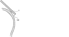
- FIG. 4 is an enlarged schematic cross-sectional view of an enlarged broken-line circle portion of the second embodiment of the bag filter air amplifying device 1 according to the present invention shown in FIG.
- the compressed air injection hole 122 can be formed, for example, by providing a plurality of convex portions T toward the R-shaped inclined surface 111 at predetermined intervals on the inner wall surface of a compressed air guide wall 123 described later. At this time, it is possible to freely adjust the width of the compressed air injection hole 122 by changing the height of the convex portion T.
- the specific forms such as the size and shape are not particularly limited as long as the effects of the present invention are not impaired, and can be freely selected according to the amount of compressed air to be introduced, the target ejection speed, and the like. Can be designed.
- FIG. 5 is a schematic plan view of a third embodiment of the bag filter air amplifying device 1 according to the present invention as viewed from the bottom side.
- the convex part T is provided along the flow direction of compressed air.
- the convex portion T rectifies the compressed air introduced from the compressed air introduction port 121 and guides it to the compressed air injection hole 122. It is also possible to provide a rectifying action.
- the compressed air guide wall 123 has a curved shape in order to guide the compressed air introduced from the compressed air introduction port 121 to the compressed air injection hole 122.
- a specific form of the compressed air guide wall 123 is not limited as long as it has at least a curved shape in order to guide the compressed air introduced from the compressed air introduction port 121 to the compressed air injection hole 122.
- the other structure is not particularly limited as long as the above effect is not impaired, and the structure can be freely designed according to the target bag filter or the form of the compressed air introduction pipe 2 to be connected.
- the compressed air guide wall 123 is designed so as to cover the R-shaped inclined surface 111, so that fine dust or powder that has passed through the filter can be obtained. Is attached and buried outside (upper part) of the compressed air guide wall 123. That is, dust and powder are not attached or buried on the R-shaped inclined surface 111. Therefore, the compressed air injection from the compressed air injection hole 122 is not hindered, and a stable Coanda effect can be produced in the long term. As a result, an excellent air amplification effect stable in the long term is maintained. can do. It should be noted that the dust and powder adhering to and buried in the outside (upper part) of the compressed air guide wall 123 may be removed by periodically wiping or sucking.
- the conventional bag filter air amplifying apparatus is designed so that the center of the compressed air inlet is located on the same line as the apex of the curve of the compressed air guiding wall (for example, see Patent Document 3 FIG. 3). reference).
- the center of the compressed air inlet 121 is designed to be located on the same line as the curved apex of the compressed air guiding wall 123, as in the prior art.
- the compressed air introduced from the compressed air inlet 121 collides with the compressed air guide wall 123 by making the center of the compressed air inlet 121 outside the apex of the curve of the compressed air guide wall 123, the compressed air is compressed. Air is guided toward the apex of the curve at a higher position, and can be prevented from flowing in the direction opposite to the compressed air injection hole 122. As a result, the compressed air introduced from the compressed air introduction port 121 can be guided to the compressed air injection hole 122 in a state where the compression loss is minimized.
- FIG. 6 is a schematic cross-sectional view of the first embodiment of the bag filter air amplification system 10 according to the present invention as viewed from the side.
- the bag filter air amplifying system 10 according to the present invention includes at least the bag filter air amplifying apparatus 1 according to the present invention and the compressed air introduction pipe 2 described above.
- the bag filter air amplifying system 10 according to the present invention may include a fixing means 3.
- each part will be described in detail.
- the details of the bag filter air amplifying device 1 according to the present invention are the same as those described above, and therefore the description thereof is omitted here.
- Compressed air introduction pipe 2 The compressed air introduction pipe 2 introduces compressed air into the compressed air introduction part 12 of the air amplifying device 1.
- the specific form such as the thickness and length of the compressed air introduction pipe 2 is not particularly limited as long as the effects of the present invention are not impaired, and can be freely designed according to the target bag filter, the form of the installation location, and the like. it can.
- the arrangement of the compressed air introduction pipe 2 is not particularly limited as long as the effect of the present invention is not impaired, and can be freely designed according to the form of the installation place.
- the air amplifier 1 It is preferable to install in the lower part of the compressed air introduction part 12 so that it may communicate with this compressed air introduction part 12.
- a compressed air introduction pipe above the external air inlet.
- the air flow may be obstructed when the external air is attracted from the external air inlet, and the amount of air to be attracted may decrease. The effect may be reduced. Therefore, in the present invention, it is preferable to install the compressed air introduction pipe 2 below the compressed air introduction part 12.
- the specific cross-sectional shape of the compressed air introduction pipe 2 is not particularly limited as long as the effects of the present invention are not impaired, and can be freely designed according to the form of the installation location.
- connection surface of the compressed air introduction part 12 to the compressed air introduction pipe 2 and the compressed air introduction pipe 2 are
- the connecting surface with the compressed air introduction portion 12 can be formed as a spherical surface.
- This is the same connection surface as the conventional bag filter air amplification system.
- the compressed air introduction part and the compressed air introduction pipe having a circular or elliptical cross section are connected by welding the outside (see C in FIG. 6).
- a hole is provided in the spherical surface and connected, there is a problem that compressed air leaks from a connecting portion other than the welded portion C. This is one of the causes that cause a decrease in air amplification efficiency. It was.
- connection surface of the compressed air introduction part 12 with the compressed air introduction pipe 2 and the compression of the compressed air introduction pipe 2 By designing the connection surface with the air introduction part 12 to be parallel to each other, leakage of compressed air can be prevented.
- the compressed air introduction part 12 and the compressed air introduction pipe 2 can be connected by welding as in the second embodiment shown in FIG. 7, but as in the first embodiment shown in FIG. It is also possible to seal using the packing P. By connecting with the packing P, it becomes possible to easily remove the air amplifier 1 for bag filter from the compressed air introduction pipe 2, and it becomes necessary to replace the single item due to breakage or to urgently close the filter cloth hole. Etc.
- the number of compressed air introduction pipes 2 provided in the bag filter air amplification system 10 according to the present invention is not particularly limited as long as the effects of the present invention are not impaired, and one or two according to the form of the installation location. It is also possible to provide more than one.
- the number of compressed air introduction pipes 2 is particularly preferably one.
- a plurality of compressed air introduction ports 121 are also provided.
- the compressed air introduced from the plurality of compressed air introduction ports 121 is contained inside the compressed air introduction unit 12. In rare cases, the flow may interfere with each other. In this case, the injection speed of the compressed air from the compressed air injection hole 122 decreases, and as a result, the air amplification factor may be decreased.
- the number of the compressed air introduction pipes 2 is one, it is possible to prevent a reduction in the compression rate of the air due to the branching of the pipes, and between the compressed air introduced inside the compressed air introduction section 12. Interference can be suppressed, and as a result, an excellent air amplification effect can be maintained.
- FIG. 8 is a schematic perspective view schematically showing a third embodiment of the air amplification system 10 for a bag filter according to the present invention.
- a compressed air guide plate 4 is provided at a connection portion between the compressed air introduction portion 12 and the compressed air introduction pipe 2.
- the compressed air guide plate 4 is not essential in the present invention, but can be provided to guide the introduction of the compressed air A from the compressed air introduction pipe 2 to the compressed air introduction part 12.
- the compressed air A is introduced into the compressed air introduction pipe 2 in one direction (see arrow A in FIG. 8), depending on the compression rate and introduction speed of the compressed air A, In some cases, the air may be introduced into the compressed air introduction section 12 along the flow. Further, in an actual site, since there are many cases where 8 to 9 apparatuses 1 are arranged in a lane, the compressed air introduction section 12 becomes more downstream in the introduction direction of the compressed air A in the compressed air introduction pipe 2. The amount and pressure of air introduced into the apparatus may increase, and it may be difficult to stably introduce the compressed air A to each device 1.
- the compressed air guide plate 4 is provided at the connecting portion between the compressed air introduction part 12 and the compressed air introduction pipe 2, the compressed air is compressed to the compressed air introduction part 12 at an angle close to perpendicular to the compressed air introduction pipe 2. Air A can be introduced. Further, even when a plurality of devices 1 are arranged in one lane, the amount and pressure of compressed air A introduced into each device 1 can be kept constant, and the compressed air A can be stably introduced. .
- the installation location of the compressed air guide plate 4 is particularly suitable if the introduction of the compressed air A from the compressed air introduction pipe 2 to the compressed air introduction section 12 can be guided at an angle close to the perpendicular to the compressed air introduction pipe 2. It is not limited. It can be installed upstream of the compressed air inlet 121 as in the third embodiment of FIG. 8, or is installed in the center of the compressed air inlet 121, for example, as in the fourth embodiment of FIG. It is also possible. Particularly in the present invention, in order to guide at an angle close to perpendicular to the compressed air introduction pipe 2, it is preferably installed upstream from the center of the compressed air introduction port 121, and the most upstream of the compressed air introduction port 121. More preferably, it is installed on the side.
- the compressed air guide plate 4 can be installed in a state of protruding to the upper part of the compressed air introduction port 121 to such an extent that the air flow of the compressed air introduction unit 12 is not hindered.
- the compressed air guide plate 4 may be installed in a state connected to the compressed air introduction pipe 2 side, may be installed in a state connected to the compressed air introduction part 12 side, or the compressed air introduction pipe 2. And you may install in the state connected to both the compressed air introduction parts 12.
- FIG. 1 A block diagram illustrating an exemplary computing environment in accordance with the present disclosure.
- the configuration of the compressed air guide plate 4 can also guide the introduction of the compressed air A from the compressed air introduction pipe 2 to the compressed air introduction section 12 at an angle close to the perpendicular to the compressed air introduction pipe 2.
- it is not particularly limited, and can be freely designed according to the shape of the compressed air inlet 121, the installation location, and the like.
- the compressed air guide plate 4 having a curved shape in an R shape is used. preferable.
- the compressed air introduction port 121 when installing the compressed air guide plate 4 in the center part of the compressed air introduction port 121 like 4th Embodiment, although not shown in figure, the compressed air introduction port 121 is not shown. It is preferable to use an L-shaped compressed air guide plate 4 as a bottom surface.
- FIG. 10 is the cross-sectional schematic diagram which looked at 5th Embodiment of the air amplification system 10 for bag filters based on this invention from the side surface.
- the fixing means 3 which fixes the air amplification apparatus 1 is further provided.
- the fixing means 3 is not essential in the present invention, but by providing the fixing means 3, the horizontality of the bag filter air amplifying device 1 can be maintained.
- the bag filter air amplifying device 1 is supported only by the compressed air introduction pipe 2. As a result, the bag filter air amplifying device 1 may be inclined.
- a fixing means 3 for fixing the air amplification device 1 is further provided as in the fifth embodiment of the bag filter air amplification system 10 according to the present invention shown in FIG.
- the inclination of the air amplifying device 1 can be prevented and its horizontality can be maintained, and as a result, an excellent air amplifying effect can be maintained.
- Example demonstrated below shows an example of the typical Example of this invention, and, thereby, the range of this invention is not interpreted narrowly.
- Example 1 In Experimental Example 1, it was examined whether or not the efficiency of inflow of compressed air into the air amplifying unit and the air amplifying effect changed depending on the form of each part of the bag filter air amplifying device.
- the air amplifier for a bag filter according to the present invention the first embodiment shown in FIGS. 1 and 2, the second embodiment shown in FIG. 3, and an example of a conventional bag filter air amplifier.
- the inflow efficiency of compressed air into the air amplifier and the air amplification efficiency were compared using a single compressed air introduction pipe of the apparatus shown in FIG.
- r position of the compressed air injection hole from the center of the air amplification part
- s width of the compressed air injection hole (slit width)
- the amount of outflow air when using the bag filter air amplification system according to Example 2 was increased by 20% from 0.456 kg / sec to 0.547 kg / sec, as compared with Comparative Example 1 which is a conventional product.
- the outflow air amount was 0.595 kg / sec, an increase of 30%.
- the compressed air inflow rate when using the bag filter air amplification system according to Examples 1 and 2 is also increased by 16% from 0.118 kg / sec to 0.137 kg / sec.
- the air amplification system for a bag filter according to the present invention has a significant increase in not only the air amplification factor but also the inflow efficiency of compressed air as compared with the conventional product. That is, it was shown that the air amplification system for bag filters according to the present invention can realize a high air amplification effect with less compressed air than the conventional product.
- Example 2 In Experimental Example 2, it was further investigated whether the inflow efficiency of compressed air into the air amplifying unit and the air amplifying effect were changed depending on the form of each part of the bag amplifying device.
- the bag filter air amplifying device according to the present invention the second embodiment shown in FIG. 3, and as an example of a conventional bag filter air amplifying device, the device shown in FIG. It was used to compare the inflow efficiency of compressed air to the air amplifier and the air amplification efficiency.
- Example 3 In Experimental Example 3, the change in the wind speed at the amplified air discharge port due to the difference in the form of each part of the air amplifier for bag filter, the difference in the inflow air pressure, the difference in the injection time and the injection interval was examined.
- the bag filter air amplifying device according to the present invention the second embodiment shown in FIG. 3, and as an example of a conventional bag filter air amplifying device, the device shown in FIG. Using, the wind speed at the amplified air outlet was compared.
- the devices of Example 4 and Comparative Example 3 the same devices as those of Example 3 and Comparative Example 2 used in Experimental Example 2 were used.
- the experimental examples 1 to 3 described above are all results of one apparatus. Since there are many cases where 8 to 9 devices are arranged in one lane in an actual site, it is considered that there is a greater difference between the conventional product and the present invention than the result of this experimental example. That is, by using the air amplification system for bag filters according to the present invention, very high air amplification efficiency can be realized even in an actual site where 8 to 9 devices are connected in one lane, and as a result, the back washing effect of the filter is achieved. Can be improved.
- the air amplification system for bag filter according to the present invention can realize a very high air amplification efficiency compared to the conventional product, and thus it is large (long) that a conventional backwashing effect cannot be obtained sufficiently. It is considered that it can be suitably used for a bag filter.
Landscapes
- Engineering & Computer Science (AREA)
- Physics & Mathematics (AREA)
- Fluid Mechanics (AREA)
- Mechanical Engineering (AREA)
- General Engineering & Computer Science (AREA)
- Chemical & Material Sciences (AREA)
- Chemical Kinetics & Catalysis (AREA)
- Filtering Of Dispersed Particles In Gases (AREA)
- Jet Pumps And Other Pumps (AREA)
Description
本発明は、バグフィルター用空気増幅装置に関する。より詳しくは、バグフィルターの逆洗に用いるバグフィルター用空気増幅装置および該バグフィルター用空気増幅装置を用いたバグフィルター用空気増幅システムに関する。
従来から、焼却場や一般的な工場などにおける粉塵の除去や、紛体工場などにおける紛体の収集などに、バグフィルター(濾布式集塵機)が用いられている。バグフィルターは、濾過集塵装置の一つであり、濾材として織布や不織布を用い、これを円筒状にして粉塵の除去や紛体の収集などを行う装置である。
例えば、特許文献1には、含塵空気室と浄化空気室とを選択して連結する清掃回路を設け、該回路には有毒ガス除去部材と加熱器及び温風循環ファンとを備え、浄化空気室内の空気を清掃回路を介して加熱して含塵空気室に導入し、循環して含塵空気室内を加熱し、該含塵空気室内の塵埃を有毒ガス除去部材により無害化することにより、作業者の立ち入りを可能とし、濾布の取り出し作業を容易に行うことを可能とした濾布式集塵機が開示されている。
このようなバグフィルターでは、通常時には、吸引されてきた粉塵や紛体がフィルター(特許文献1の図1では符号10)に付着し、粉塵や紛体を含有しない空気のみが排出される(特許文献1の図1では符号5側へ排出される)ことで、粉塵の除去や紛体の収集などが行われる。しかし、操業を続けていると、次第にフィルターに粉塵や紛体が付着し堆積することにより、フィルターの濾過効果が低下する。そこで、一定周期毎に、圧縮した空気をフィルターの濾過方向とは逆の方向から噴射し、フィルターに付着した粉塵や紛体を払落する、所謂、逆洗が行われている。
例えば、特許文献1の濾布式集塵機は、圧縮空気を送り込む逆噴射パイプ(特許文献1の図1では符号12)と、圧縮空気を噴射するノズル(特許文献1の図1では符号13)とを用いて、逆洗を行うことができるように設計されている。
このように、従来から一般的に行われてきた逆洗方法では、噴射された圧縮空気が外気を誘引するために、ベンチュリー効果を使い理論上は少ない圧縮空気量でフィルターの洗浄が達成できる。しかし、実際には、ノズルとフィルターの芯合わせが難しく、少しでもずれると誘引空気量が大きく減ってしまい、設計通りの性能を発揮することができないという問題があった。
また、ノズルから噴射された圧縮空気は、ベンチュリーを使用しているため、フィルターの側面に向かって広がりながら流れるので、何度も逆洗を繰り返すことで、フィルターの側面にダメージを与えるという問題もあった。更に、長いフィルターを用いる場合においては、フィルターの底面まで圧縮空気が届かず、フィルターの下部では逆洗効果が低下するという問題もあった。加えて、ベンチュリーが装着されているために、吸入空気流路が絞り部によって狭くなっており、逆洗浄しない時には、空気抵抗が増え圧力損失が発生するという問題もあった。
このような問題を解決するために、近年においては、コアンダ効果を有する空気増幅装置を用いてバグフィルターの逆洗を行うことが行われつつある。コアンダ効果を有する空気増幅装置からは、フィルターの側面とほぼ平行に逆洗用の空気が噴射されるため、フィルターの側面にダメージを与えることなく、フィルターに付着した粉塵や紛体を払落することができる。
例えば、特許文献2には、加圧空気の経路変更による圧力損失を軽減するために、加圧空気の流入口と、外部空気の流入口とが同一平面上に配置されたコアンダインジェクターが開示されている。
また、特許文献3には、圧縮空気を供給する導管を2つの分岐管に分けて、その分岐管の上部に空気増幅器を共に連結して空気増幅器から増幅された空気の圧力によって周辺装備の障害なく、より多量の周辺空気をより早い速度でバグフィルターに均一に供給して高い脱塵効果が発揮できるようにした空気増幅器を利用した圧縮空気噴射装置が開示されている。
前述のように、コアンダ効果を有する空気増幅装置を用いれば、逆噴射パイプとノズルを用いた従来の逆洗浄に比べ、高い逆洗浄効果を期待することができる。しかし、まだまだ空気増幅効率が十分でない空気増幅装置もあり、更なる開発が望まれていた。特に、バグフィルターは、通常、1レーンに8~9個連ねられている場合が多く、空気増幅器もまた、圧縮空気を送る1つの配管に8~9個連ねることになるが、1個では十分な空気増幅効率を有していても、複数連なると、その空気増幅効率が低下するという問題があった。
そこで、本発明では、空気増幅効率の優れた、バグフィルターの逆洗に適する空気増幅装置を提供することを主目的とする。
上記技術的課題を解決するために、本願発明者は空気増幅効率を向上させるための空気増幅装置の具体的な構造について鋭意研究を行った結果、圧縮空気の噴射方向が重要であることを突き止め、本発明を完成させるに至った。
即ち、本発明では、まず、バグフィルターの逆洗に用いる空気増幅装置であって、
外側へ向かって広がるR状傾斜面と、該R状傾斜面に連設して外部の空気を誘引する外部空気誘引口と、増幅された空気を排出する増幅空気排出口と、前記外部空気誘引口から前記増幅空気排出口へ渡って設けられた筒状の側壁と、が備えられた空気増幅部と、
圧縮された空気を導入する圧縮空気導入口と、圧縮空気を前記空気増幅部へ噴射する圧縮空気噴射孔と、前記圧縮空気導入口から導入された圧縮空気を前記圧縮空気噴射孔へ誘導する湾曲状の圧縮空気誘導壁と、が備えられた圧縮空気導入部と、
を少なくとも備え、
前記圧縮空気噴射孔は、前記R状傾斜面に沿って前記外部空気誘引口に設けられたバグフィルター用空気増幅装置を提供する。
従来のバグフィルター用空気増幅装置では、コアンダ効果を発生させるために圧縮空気を空気増幅部に噴射させる際、その噴射角度は、外部空気の誘引方向に対して垂直に設計することが常識であった(例えば、特許文献3図3符号(3)、明細書段落番号0022参照)。しかし、従来技術における常識から発想を転換し、本発明に係るバグフィルター用空気増幅装置では、空気増幅部への圧縮空気の噴射角度は、前記R状傾斜面に沿って、90°よりも小さい角度で噴射されることを特徴とする。
本発明に係るバグフィルター用空気増幅装置では、前記圧縮空気噴射孔を、前記R状傾斜面に沿って前記外部空気誘引口に設けるために、前記R状傾斜面を、前記圧縮空気誘導壁で覆った状態に設計する。
また、前記圧縮空気導入口の中心が、前記圧縮空気誘導壁の湾曲の頂点よりも外側に位置するように設計することが好ましい。
更に、前記増幅空気排出口の断面面積を、前記外部空気誘引口の断面面積より広く設計することが好ましい。この場合、前記圧縮空気噴射孔から噴射される圧縮空気によるコアンダ効果が少なくとも持続される部位において、前記側壁を外側へ広げることで、前記増幅空気排出口の断面面積を、前記外部空気誘引口の断面面積より広く設計することが好ましい。
本発明に係るバグフィルター用空気増幅装置では、前記圧縮空気噴射孔は、前記圧縮空気誘導壁と、前記R状傾斜面との間隙で形成することができる。この時、前記圧縮空気誘導壁の内壁面には、前記R状傾斜面へ向けて凸部を形成することが好ましい。この凸部は、圧縮空気の流動方向に沿って設けることが更に好ましい。
外側へ向かって広がるR状傾斜面と、該R状傾斜面に連設して外部の空気を誘引する外部空気誘引口と、増幅された空気を排出する増幅空気排出口と、前記外部空気誘引口から前記増幅空気排出口へ渡って設けられた筒状の側壁と、が備えられた空気増幅部と、
圧縮された空気を導入する圧縮空気導入口と、圧縮空気を前記空気増幅部へ噴射する圧縮空気噴射孔と、前記圧縮空気導入口から導入された圧縮空気を前記圧縮空気噴射孔へ誘導する湾曲状の圧縮空気誘導壁と、が備えられた圧縮空気導入部と、
を少なくとも備え、
前記圧縮空気噴射孔は、前記R状傾斜面に沿って前記外部空気誘引口に設けられたバグフィルター用空気増幅装置を提供する。
従来のバグフィルター用空気増幅装置では、コアンダ効果を発生させるために圧縮空気を空気増幅部に噴射させる際、その噴射角度は、外部空気の誘引方向に対して垂直に設計することが常識であった(例えば、特許文献3図3符号(3)、明細書段落番号0022参照)。しかし、従来技術における常識から発想を転換し、本発明に係るバグフィルター用空気増幅装置では、空気増幅部への圧縮空気の噴射角度は、前記R状傾斜面に沿って、90°よりも小さい角度で噴射されることを特徴とする。
本発明に係るバグフィルター用空気増幅装置では、前記圧縮空気噴射孔を、前記R状傾斜面に沿って前記外部空気誘引口に設けるために、前記R状傾斜面を、前記圧縮空気誘導壁で覆った状態に設計する。
また、前記圧縮空気導入口の中心が、前記圧縮空気誘導壁の湾曲の頂点よりも外側に位置するように設計することが好ましい。
更に、前記増幅空気排出口の断面面積を、前記外部空気誘引口の断面面積より広く設計することが好ましい。この場合、前記圧縮空気噴射孔から噴射される圧縮空気によるコアンダ効果が少なくとも持続される部位において、前記側壁を外側へ広げることで、前記増幅空気排出口の断面面積を、前記外部空気誘引口の断面面積より広く設計することが好ましい。
本発明に係るバグフィルター用空気増幅装置では、前記圧縮空気噴射孔は、前記圧縮空気誘導壁と、前記R状傾斜面との間隙で形成することができる。この時、前記圧縮空気誘導壁の内壁面には、前記R状傾斜面へ向けて凸部を形成することが好ましい。この凸部は、圧縮空気の流動方向に沿って設けることが更に好ましい。
以上の本発明に係るバグフィルター用空気増幅装置は、前記空気増幅装置の前記圧縮空気導入部へ圧縮空気を導入する圧縮空気導入管を加えて、バグフィルターの逆洗に用いる空気増幅システムとして好適に用いることができる。
本発明に係るバグフィルター用空気増幅システムは、本発明に係るバグフィルター用空気増幅装置を備えていれば、その他の構成は特に限定されないが、前記圧縮空気導入部の前記圧縮空気導入管との接続面と、前記圧縮空気導入管の前記圧縮空気導入部との接続面とを、互いに平行に形成することが好ましい。
また、前記圧縮空気導入部と前記圧縮空気導入管との接続部は、パッキンにてシールすることが好ましい。
更に、前記接続部には、前記圧縮空気導入管から前記圧縮空気導入部への圧縮空気の導入を誘導する圧縮空気誘導板を備えることが好ましい。
加えて、前記空気増幅装置を固定する固定手段を備えることが好ましい。
本発明に係るバグフィルター用空気増幅システムは、本発明に係るバグフィルター用空気増幅装置を備えていれば、その他の構成は特に限定されないが、前記圧縮空気導入部の前記圧縮空気導入管との接続面と、前記圧縮空気導入管の前記圧縮空気導入部との接続面とを、互いに平行に形成することが好ましい。
また、前記圧縮空気導入部と前記圧縮空気導入管との接続部は、パッキンにてシールすることが好ましい。
更に、前記接続部には、前記圧縮空気導入管から前記圧縮空気導入部への圧縮空気の導入を誘導する圧縮空気誘導板を備えることが好ましい。
加えて、前記空気増幅装置を固定する固定手段を備えることが好ましい。
本発明によれば、コアンダ効果を有する従来の空気増幅装置に比べ、空気増幅効率を飛躍的に向上させることが可能である。
以下、本発明を実施するための好適な形態について図面を参照としながら説明する。なお、以下に説明する実施形態は、本発明の代表的な実施形態の一例を示したものであり、これにより本発明の範囲が狭く解釈されることはない。
<1.バグフィルター用空気増幅装置1>
図1は、本発明に係るバグフィルター用空気増幅装置1の第1実施形態を模式的に示す模式斜視図である。図2は、本発明に係るバグフィルター用空気増幅装置1の第1実施形態を、側面から視た断面模式図である。
図1は、本発明に係るバグフィルター用空気増幅装置1の第1実施形態を模式的に示す模式斜視図である。図2は、本発明に係るバグフィルター用空気増幅装置1の第1実施形態を、側面から視た断面模式図である。
本発明に係るバグフィルター用空気増幅装置1は、大別して、空気増幅部11と、圧縮空気導入部12と、を少なくとも備える。そして、空気増幅部11は、R状傾斜面111と、外部空気誘引口112と、増幅空気排出口113と、側壁114と、を備え、圧縮空気導入部12は、圧縮空気導入口121と、圧縮空気噴射孔122と、圧縮空気誘導壁123と、を備える。以下、各部について、詳細に説明する。
(1)空気増幅部11
空気増幅部11は、後述する圧縮空気導入部12から噴射された圧縮空気によるコアンダ効果を利用して、空気を増幅させる部分である。
空気増幅部11は、後述する圧縮空気導入部12から噴射された圧縮空気によるコアンダ効果を利用して、空気を増幅させる部分である。
(a)R状傾斜面111
R状傾斜面111は、後述する外部空気誘引口112へ、外部空気を誘導するために、外側へ向かって広がった形態を呈する。R状傾斜面111の大きさ、傾斜角度などの具体的態様は、本発明の効果を損なわない限り特に限定されず、目的のバグフィルターなどに合わせて自由に設計することができる。
R状傾斜面111は、後述する外部空気誘引口112へ、外部空気を誘導するために、外側へ向かって広がった形態を呈する。R状傾斜面111の大きさ、傾斜角度などの具体的態様は、本発明の効果を損なわない限り特に限定されず、目的のバグフィルターなどに合わせて自由に設計することができる。
(b)外部空気誘引口112
外部空気誘引口112は、R状傾斜面111に連設されており、外部の空気を誘引する部分である。外部空気誘引口112の開口面積や開口形状は、本発明の効果を損なわない限り特に限定されず、目的のバグフィルターに用いる濾布の大きさなどに合わせて自由に設計することができる。一例を挙げると、例えば、バグフィルターの濾布の直径が150mm程度の場合、内径70~80mmに外部空気誘引口112を設計することができる。
外部空気誘引口112は、R状傾斜面111に連設されており、外部の空気を誘引する部分である。外部空気誘引口112の開口面積や開口形状は、本発明の効果を損なわない限り特に限定されず、目的のバグフィルターに用いる濾布の大きさなどに合わせて自由に設計することができる。一例を挙げると、例えば、バグフィルターの濾布の直径が150mm程度の場合、内径70~80mmに外部空気誘引口112を設計することができる。
(c)増幅空気排出口113
増幅空気排出口113は、増幅された空気をバグフィルターへ向かって排出する部分である。増幅空気排出口113の開口面積や開口形状は、本発明の効果を損なわない限り特に限定されず、目的のバグフィルターに用いる濾布の大きさなどに合わせて自由に設計することができる。一例を挙げると、例えば、バグフィルターの濾布の直径が150mm程度の場合、内径70~80mmに増幅空気排出口113を設計することができる。
増幅空気排出口113は、増幅された空気をバグフィルターへ向かって排出する部分である。増幅空気排出口113の開口面積や開口形状は、本発明の効果を損なわない限り特に限定されず、目的のバグフィルターに用いる濾布の大きさなどに合わせて自由に設計することができる。一例を挙げると、例えば、バグフィルターの濾布の直径が150mm程度の場合、内径70~80mmに増幅空気排出口113を設計することができる。
従来のバグフィルター用空気増幅装置では、外部空気誘引口112と増幅空気排出口113は、同一の開口面積および開口形状に設計されていた(例えば、特許文献3図3参照)。本発明に係るバグフィルター用空気増幅装置1においても、従来と同様に、外部空気誘引口112と増幅空気排出口113を、同一の開口面積および開口形状に設計することも可能であるが、図3に示す第2実施形態のように、増幅空気排出口113の断面面積を、外部空気誘引口112の断面面積より広く設計することが好ましい。増幅空気排出口113の断面面積を、外部空気誘引口112の断面面積より広く設計することで、空気増幅効率が更に向上することを、本願発明者が突き止めた。
増幅空気排出口113の断面面積を、外部空気誘引口112の断面面積より広く設計する方法としては、後述する側壁114の所定部分を外側へ広げる方法がある。この際、圧縮空気噴射孔122から噴射される圧縮空気によるコアンダ効果が少なくとも持続される部位において、側壁114を外側へ広げることが好ましい(図3符号W参照)。コアンダ効果が少なくとも持続される部位において、側壁114を外側へ広げることで、確実に、空気増幅効率を向上させることができる。
(d)側壁114
側壁114は、外部空気誘引口112から増幅空気排出口113へ渡って設けられ、外部空気誘引口112から誘引された外部空気と、後述する圧縮空気噴射孔122から噴射された圧縮空気と、を増幅空気排出口113へ誘導するために、筒状を呈する。側壁114の長さなどの具体的態様は、本発明の効果を損なわない限り特に限定されず、目的のバグフィルターなどに合わせて自由に設計することができる。
側壁114は、外部空気誘引口112から増幅空気排出口113へ渡って設けられ、外部空気誘引口112から誘引された外部空気と、後述する圧縮空気噴射孔122から噴射された圧縮空気と、を増幅空気排出口113へ誘導するために、筒状を呈する。側壁114の長さなどの具体的態様は、本発明の効果を損なわない限り特に限定されず、目的のバグフィルターなどに合わせて自由に設計することができる。
(2)圧縮空気導入部12
圧縮空気導入部12は、後述する圧縮空気導入管2から送られてくる圧縮空気を、本発明に係るバグフィルター用空気増幅装置1の内部へ導入するための部位である。
圧縮空気導入部12は、後述する圧縮空気導入管2から送られてくる圧縮空気を、本発明に係るバグフィルター用空気増幅装置1の内部へ導入するための部位である。
(a)圧縮空気導入口121
圧縮空気導入口121は、後述する圧縮空気導入管2から送られてくる圧縮空気を、圧縮空気導入部12の内部へ導入するための部位である。圧縮空気導入口121の開口面積や開口形状など具体的な態様は、本発明の効果を損なわない限り特に限定されず、目的のバグフィルターや接続する圧縮空気導入管2の形態などに合わせて自由に設計することができる。
圧縮空気導入口121は、後述する圧縮空気導入管2から送られてくる圧縮空気を、圧縮空気導入部12の内部へ導入するための部位である。圧縮空気導入口121の開口面積や開口形状など具体的な態様は、本発明の効果を損なわない限り特に限定されず、目的のバグフィルターや接続する圧縮空気導入管2の形態などに合わせて自由に設計することができる。
(b)圧縮空気噴射孔122
圧縮空気噴射孔122は、圧縮空気導入口121から導入された圧縮空気を、空気増幅部11へ噴射するための部位である。本発明に係るバグフィルター用空気増幅装置1では、この圧縮空気噴射孔122が、R状傾斜面111に沿って外部空気誘引口112に設けられていることを特徴とする。
圧縮空気噴射孔122は、圧縮空気導入口121から導入された圧縮空気を、空気増幅部11へ噴射するための部位である。本発明に係るバグフィルター用空気増幅装置1では、この圧縮空気噴射孔122が、R状傾斜面111に沿って外部空気誘引口112に設けられていることを特徴とする。
従来のバグフィルター用空気増幅装置では、圧縮空気噴射孔は、R状傾斜面より外側に設けられていた。即ち、コアンダ効果を発生させるために圧縮空気を空気増幅部に噴射させる際、圧縮空気導入口からの噴射角度は、外部空気の誘引方向に対して垂直に設計することが常識であった(例えば、特許文献3図3符号(3)、明細書段落番号0022参照)。しかし、従来技術における常識から発想を転換し、本発明に係るバグフィルター用空気増幅装置1では、圧縮空気噴射孔122が、R状傾斜面111に沿って外部空気誘引口112に設けられていることを特徴とする。即ち、圧縮空気導入口121から空気増幅部11への圧縮空気の噴射角度は、前記R状傾斜面111に沿って、外部空気の誘引方向に対して90°よりも小さい角度で噴射されることを特徴とする。このように、圧縮空気導入口121から空気増幅部11への圧縮空気の噴射角度は、前記R状傾斜面111に沿って、外部空気の誘引方向に対して90°よりも小さい角度で噴射されることにより、従来のバグフィルター用空気増幅装置に比べ、空気増幅効率を飛躍的に向上させることに成功した。
圧縮空気噴射孔122は、後述する圧縮空気誘導壁123と、R状傾斜面111との間隙で形成することができる。圧縮空気噴射孔122を形成する間隙の幅は、本発明の効果を損なわない限り特に限定されず、導入される圧縮空気の量や目的の噴出速度などに合わせて自由に設計することができる。一例を挙げると、例えば、幅0.3~2mmに圧縮空気噴射孔122を形成する間隙を設計することができる。本発明に係るバグフィルター用空気増幅装置1の圧縮空気噴射孔122からは、超音速で圧縮空気が噴射される。この空気の噴射によって、外部空気誘引口112付近にはコアンダ効果が発生し、空気増幅部11へ外部空気が誘引される。その結果、非常に高効率で空気を増幅させることが可能である。
図4は、図3に示す本発明に係るバグフィルター用空気増幅装置1の第2実施形態の破線円部分を、拡大した拡大断面模式図である。圧縮空気噴射孔122は、例えば、後述する圧縮空気誘導壁123の内壁面に、R状傾斜面111へ向けた凸部Tを所定間隔で複数設けることで、形成することができる。この際、この凸部Tの高さを変更することで、圧縮空気噴射孔122の幅を、自由に調整することも可能である。
凸部Tを設ける場合、その大きさや形状などの具体的な形態は、本発明の効果を損なわない限り特に限定されず、導入される圧縮空気の量や目的の噴出速度などに合わせて自由に設計することができる。
図5は、本発明に係るバグフィルター用空気増幅装置1の第3実施形態を、底部側から視た平面模式図である。第3実施形態では、凸部Tを、圧縮空気の流動方向に沿って設けている。このように、凸部Tを圧縮空気の流動方向に沿って設けることで、凸部Tに、圧縮空気導入口121から導入された圧縮空気を整流させて圧縮空気噴射孔122へと導くための整流作用を付与することも可能である。
(c)圧縮空気誘導壁123
圧縮空気誘導壁123は、圧縮空気導入口121から導入された圧縮空気を、圧縮空気噴射孔122へ誘導するために、湾曲状の形態を成す。圧縮空気誘導壁123の具体的な形態は、圧縮空気導入口121から導入された圧縮空気を、圧縮空気噴射孔122へ誘導するために、少なくとも湾曲状の形態を成していれば、本発明の効果を損なわない限りその他の構造は特に限定されず、目的のバグフィルターや接続する圧縮空気導入管2の形態などに合わせて自由に設計することができる。
圧縮空気誘導壁123は、圧縮空気導入口121から導入された圧縮空気を、圧縮空気噴射孔122へ誘導するために、湾曲状の形態を成す。圧縮空気誘導壁123の具体的な形態は、圧縮空気導入口121から導入された圧縮空気を、圧縮空気噴射孔122へ誘導するために、少なくとも湾曲状の形態を成していれば、本発明の効果を損なわない限りその他の構造は特に限定されず、目的のバグフィルターや接続する圧縮空気導入管2の形態などに合わせて自由に設計することができる。
従来のバグフィルター用空気増幅装置では、R状傾斜面は露出した状態であるため(例えば、特許文献3図3参照)、バグフィルターによる操業が続けられるに従って、フィルターを通過してしまった微細な粉塵や紛体が、R状傾斜面の上に、付着・埋積されてくる。R状傾斜面上に付着・埋積された粉塵や紛体は、圧縮空気噴射孔からの圧縮空気の噴射の妨げとなり、コアンダ効果を低下させ、その結果、空気増幅率の低下を招く原因となっていた。
一方、本発明に係るバグフィルター用空気増幅装置1では、圧縮空気誘導壁123は、R状傾斜面111を覆った状態に設計されているため、フィルターを通過してしまった微細な粉塵や紛体は、圧縮空気誘導壁123の外部(上部)に付着・埋積される。即ち、粉塵や紛体が、R状傾斜面111の上に、付着・埋積されることがない。そのため、圧縮空気噴射孔122からの圧縮空気の噴射の妨げとなることがなく、長期的に安定したコアンダ効果を生じさせることができ、その結果、長期的に安定した優れた空気増幅効果を維持することができる。なお、圧縮空気誘導壁123の外部(上部)に付着・埋積された粉塵や紛体は、定期的に払拭、吸引などを行って除去すればよい。
また、従来のバグフィルター用空気増幅装置では、圧縮空気導入口の中心が、圧縮空気誘導壁の湾曲の頂点と、同一ライン上に位置するように設計されていた(例えば、特許文献3図3参照)。本発明に係るバグフィルター用空気増幅装置1においても、従来と同様に、圧縮空気導入口121の中心が、圧縮空気誘導壁123の湾曲の頂点と、同一ライン上に位置するように設計することも可能ではあるが、圧縮空気導入口121の中心が、圧縮空気誘導壁123の湾曲の頂点よりも外側に位置するように設計することが好ましい(図2破線矢印参照)。圧縮空気導入口121の中心が、圧縮空気誘導壁123の湾曲の頂点よりも外側にすることで、圧縮空気導入口121から導入された圧縮空気が、圧縮空気誘導壁123に衝突した際、圧縮空気は更に高い位置にある湾曲の頂点方向へと導かれ、圧縮空気噴射孔122と逆方向へ流れるのを防止することができる。その結果、圧縮空気導入口121から導入された圧縮空気を、圧縮損失を最小限に抑えた状態で、圧縮空気噴射孔122へと導くことができる。
<2.バグフィルター用空気増幅システム10>
図6は、本発明に係るバグフィルター用空気増幅システム10の第1実施形態を側面から視た断面模式図である。本発明に係るバグフィルター用空気増幅システム10は、前述した本発明に係るバグフィルター用空気増幅装置1と、圧縮空気導入管2と、を少なくとも備える。また、本発明に係るバグフィルター用空気増幅システム10には、固定手段3を備えることもできる。以下、各部について、詳細に説明する。なお、本発明に係るバグフィルター用空気増幅装置1の詳細は、前述と同様であるため、ここでは説明を割愛する。
図6は、本発明に係るバグフィルター用空気増幅システム10の第1実施形態を側面から視た断面模式図である。本発明に係るバグフィルター用空気増幅システム10は、前述した本発明に係るバグフィルター用空気増幅装置1と、圧縮空気導入管2と、を少なくとも備える。また、本発明に係るバグフィルター用空気増幅システム10には、固定手段3を備えることもできる。以下、各部について、詳細に説明する。なお、本発明に係るバグフィルター用空気増幅装置1の詳細は、前述と同様であるため、ここでは説明を割愛する。
(1)圧縮空気導入管2
圧縮空気導入管2は、空気増幅装置1の前記圧縮空気導入部12へ圧縮空気を導入する。圧縮空気導入管2の太さや長さなどの具体的な形態は、本発明の効果を損なわない限り特に限定されず、目的のバグフィルター、設置場所の形態などに合わせて自由に設計することができる。
圧縮空気導入管2は、空気増幅装置1の前記圧縮空気導入部12へ圧縮空気を導入する。圧縮空気導入管2の太さや長さなどの具体的な形態は、本発明の効果を損なわない限り特に限定されず、目的のバグフィルター、設置場所の形態などに合わせて自由に設計することができる。
また、圧縮空気導入管2の配置についても本発明の効果を損なわない限り特に限定されず、設置場所の形態などに合わせて自由に設計することができるが、本発明においては、空気増幅装置1の圧縮空気導入部12に連通するように、圧縮空気導入部12の下部に設置することが好ましい。例えば、特許文献2に記載のコアンダインジェクターのように、外部空気誘引口の上部に、圧縮空気導入管を設置することも理論的には可能である。しかしながら、外部空気誘引口の上部に圧縮空気導入管を設置すると、外部空気誘引口からの外部空気の誘引の際に空気の流れの障害となり、誘引する空気量が低下する場合があり、空気増幅効果が低下する恐れがある。そのため、本発明においては、圧縮空気導入管2を圧縮空気導入部12の下部に設置することが好ましい。
更に、圧縮空気導入管2の具体的な断面形状についても、本発明の効果を損なわない限り特に限定されず、設置場所の形態などに合わせて自由に設計することができる。本発明においては特に、図6の第1実施形態に示すように、圧縮空気導入部12の圧縮空気導入管2との接続面と、圧縮空気導入管2の前記圧縮空気導入部12との接続面とが、互いに平行となるように設計することが好ましい。
例えば、図7に示す本発明に係るバグフィルター用空気増幅システム10の第2実施形態のように、圧縮空気導入部12の圧縮空気導入管2との接続面と、圧縮空気導入管2の前記圧縮空気導入部12との接続面とを、いずれも球面で形成することも可能である。これは、従来のバグフィルター用空気増幅システムと同様の接続面である。従来のバグフィルター用空気増幅システムでは、断面が円形または楕円形の圧縮空気導入部と圧縮空気導入管とを、外側を溶接(図6符号C参照)することで接続していた。しかし、この場合、球面に孔を設けて接続することになるため、溶接部C以外の接続部分から、圧縮空気が漏れ出るといった問題があり、これが、空気増幅効率の低下を招く原因の一つとなっていた。
一方、図6に示す本発明に係るバグフィルター用空気増幅システム10第1実施形態のように、圧縮空気導入部12の圧縮空気導入管2との接続面と、圧縮空気導入管2の前記圧縮空気導入部12との接続面とが、互いに平行となるように設計することで、圧縮空気の漏出を防止することができる。
圧縮空気導入部12と圧縮空気導入管2との接続は、図7に示す第2実施形態のように、溶接により行うことも可能であるが、図6に示す第1実施形態のように、パッキンPを用いてシールすることも可能である。パッキンPを用いて接続することにより、圧縮空気導入管2からバグフィルター用空気増幅装置1を容易に取り外すことが可能となり、破損による単品交換や、緊急に濾布穴を塞ぐ必要が生じた場合などに対応可能である。
加えて、本発明に係るバグフィルター用空気増幅システム10に備える圧縮空気導入管2の数も、本発明の効果を損なわない限り特に限定されず、設置場所の形態などに合わせて1本或いは2本以上の複数本、備えることも可能である。本発明では特に、圧縮空気導入管2の数は、1本にすることが好ましい。圧縮空気導入管2を複数本設置する場合、通常、1本の管を分岐させて複数本とするため、分岐させることで空気の圧縮率が低下し、バグフィルター用空気増幅装置1へ導入される圧縮空気量が低下する場合がある。この場合、バグフィルター用空気増幅装置1内におけるコアンダ効果も低下し、その結果、空気増幅率を低下させる恐れがある。
また、圧縮空気導入管2を複数本設置する場合、圧縮空気導入口121も複数設けることになるが、複数の圧縮空気導入口121から導入された圧縮空気は、圧縮空気導入部12の内部で、稀に、その流れを干渉し合う場合がある。この場合、圧縮空気噴射孔122からの圧縮空気の噴射速度が低下し、その結果、空気増幅率を低下させる恐れがある。
一方、圧縮空気導入管2の数を1本とすれば、管の分岐に伴う空気の圧縮率の低下を防止することができ、また、圧縮空気導入部12の内部で導入された圧縮空気同士の干渉を抑制することができ、その結果、優れた空気増幅効果を維持することができる。
図8は、本発明に係るバグフィルター用空気増幅システム10の第3実施形態を模式的に示す模式斜視図である。第3実施形態では、圧縮空気導入部12と圧縮空気導入管2との接続部に、圧縮空気誘導板4を備える。この圧縮空気誘導板4は、本発明において必須ではないが、圧縮空気導入管2から圧縮空気導入部12への圧縮空気Aの導入を誘導するために備えることができる。
圧縮空気Aは、圧縮空気導入管2の中を、一方方向(図8中矢印A参照)で導入されてくるため、圧縮空気Aの圧縮率や導入速度によっては、圧縮空気導入管2中の流れに沿って、圧縮空気導入部12へ斜めに導入されてしまう場合がある。また、実際の現場においては、1レーンに装置1を8~9台連ねて配置する場合が多いため、圧縮空気導入管2の圧縮空気Aの導入方向の下流へ行くほど、圧縮空気導入部12へ導入される空気の量や圧力が大きくなり、各装置1に対して、安定的に圧縮空気Aを導入することが難しい場合がある。そこで、圧縮空気導入部12と圧縮空気導入管2との接続部に、圧縮空気誘導板4を備えれば、圧縮空気導入管2に対して垂直に近い角度で圧縮空気導入部12への圧縮空気Aの導入が可能になる。また、1レーンに複数の装置1を配置する場合においても、各装置1に対する圧縮空気Aの導入量や圧力を一定に保つことができ、安定的に圧縮空気Aを導入することが可能となる。
圧縮空気誘導板4の設置箇所は、圧縮空気導入管2から圧縮空気導入部12への圧縮空気Aの導入を、圧縮空気導入管2に対して垂直に近い角度で誘導することができれば、特に限定されない。図8の第3実施形態のように圧縮空気導入口121の上流側に設置することもできるし、例えば、図9の第4実施形態のように、圧縮空気導入口121の中央部に設置することも可能である。本発明では特に、圧縮空気導入管2に対して垂直に近い角度で誘導するためには、圧縮空気導入口121の中央部から上流側に設置することが好ましく、圧縮空気導入口121の最上流側に設置することがより好ましい。
また、圧縮空気誘導板4は、圧縮空気導入部12の空気の流れを妨げない程度に、圧縮空気導入口121の上部へ突き出した状態で設置することも可能である。
更に、圧縮空気誘導板4は、圧縮空気導入管2側と接続した状態で設置しても良いし、圧縮空気導入部12側と接続した状態で設置しても良いし、圧縮空気導入管2および圧縮空気導入部12の両方に接続した状態で設置しても良い。
加えて、圧縮空気誘導板4の形態も、圧縮空気導入管2から圧縮空気導入部12への圧縮空気Aの導入を、圧縮空気導入管2に対して垂直に近い角度で誘導することができれば、特に限定されず、圧縮空気導入口121の形状、設置箇所などに応じて、自由に設計することができる。例えば、第3実施形態のように、楕円形の圧縮空気導入口121の最上流側に圧縮空気誘導板4を設置する場合は、R状に湾曲した形態の圧縮空気誘導板4を用いることが好ましい。また、第4実施形態のように、圧縮空気導入口121の中央部に圧縮空気誘導板4を設置する場合は、平板状の圧縮空気誘導板4や、図示しないが、圧縮空気導入口121を底面とするL字形状の圧縮空気誘導板4を用いることが好ましい。
(2)固定手段3
図10は、本発明に係るバグフィルター用空気増幅システム10の第5実施形態を側面から視た断面模式図である。第5実施形態では、空気増幅装置1を固定する固定手段3を更に備える。固定手段3は本発明においては必須ではないが、固定手段3を設けることで、バグフィルター用空気増幅装置1の水平性を保つことができる。
図10は、本発明に係るバグフィルター用空気増幅システム10の第5実施形態を側面から視た断面模式図である。第5実施形態では、空気増幅装置1を固定する固定手段3を更に備える。固定手段3は本発明においては必須ではないが、固定手段3を設けることで、バグフィルター用空気増幅装置1の水平性を保つことができる。
通常、バグフィルターのメンテナンスなどを行う際、バグフィルター用空気増幅システム10上を、人が移動する場合がある。この場合、例えば、図6に示す第1実施形態や図7に示す第2実施形態では、バグフィルター用空気増幅装置1は、圧縮空気導入管2のみで支えられているため、人の重さによって、バグフィルター用空気増幅装置1が傾いてしまう可能性がある。
一方、図10に示す本発明に係るバグフィルター用空気増幅システム10の第5実施形態のように、空気増幅装置1を固定する固定手段3を更に備えれば、人の重さによるバグフィルター用空気増幅装置1の傾きを防止して、その水平性を維持することができ、その結果、優れた空気増幅効果を維持することができる。
以下、実施例に基づいて本発明を更に詳細に説明する。なお、以下に説明する実施例は、本発明の代表的な実施例の一例を示したものであり、これにより本発明の範囲が狭く解釈されることはない。
<実験例1>
実験例1では、バグフィルター用空気増幅装置の各部での形態の違いにより、空気増幅部への圧縮空気の流入効率および空気増幅効果が変化するか否かを調べた。具体的には、本発明に係るバグフィルター用空気増幅装置の例として、図1および図2に示す第1実施形態、図3に示す第2実施形態、従来のバグフィルター用空気増幅装置の例として、特許文献3の図3に示す装置の圧縮空気導入管が1本のものを用いて、空気増幅部への圧縮空気の流入効率および空気増幅効率を比較した。
実験例1では、バグフィルター用空気増幅装置の各部での形態の違いにより、空気増幅部への圧縮空気の流入効率および空気増幅効果が変化するか否かを調べた。具体的には、本発明に係るバグフィルター用空気増幅装置の例として、図1および図2に示す第1実施形態、図3に示す第2実施形態、従来のバグフィルター用空気増幅装置の例として、特許文献3の図3に示す装置の圧縮空気導入管が1本のものを用いて、空気増幅部への圧縮空気の流入効率および空気増幅効率を比較した。
(1)実験に用いた装置の詳細
実験例1で用いたバグフィルター用空気増幅装置の詳細は、下記に示す表1の通りである。
実験例1で用いたバグフィルター用空気増幅装置の詳細は、下記に示す表1の通りである。

(2)実験方法
実施例1、2および比較例1に係るバグフィルター用空気増幅システムの圧縮空気導入管に、5気圧の圧縮空気を0.1秒間流し、空気増幅部への圧縮空気流入量と、増幅空気排出口からの流出空気量とを測定した。空気増幅部への圧縮空気の流入量の理論値を下記式(1)~(3)に基づいて算出し、算出した流入量(理論値)と測定した圧縮空気流入量とから、流入効率を算出した。また、測定した圧縮空気流入量と流出空気量から、空気増幅効率(流出空気量/圧縮空気流入量)を算出した。なお、実験は、それぞれの値が平衡となった時点で終了した。
実施例1、2および比較例1に係るバグフィルター用空気増幅システムの圧縮空気導入管に、5気圧の圧縮空気を0.1秒間流し、空気増幅部への圧縮空気流入量と、増幅空気排出口からの流出空気量とを測定した。空気増幅部への圧縮空気の流入量の理論値を下記式(1)~(3)に基づいて算出し、算出した流入量(理論値)と測定した圧縮空気流入量とから、流入効率を算出した。また、測定した圧縮空気流入量と流出空気量から、空気増幅効率(流出空気量/圧縮空気流入量)を算出した。なお、実験は、それぞれの値が平衡となった時点で終了した。

u:流速
A:流路の断面積


s:圧縮空気噴射孔の幅(スリット幅)
(3)結果
結果を下記の表2に示す。
結果を下記の表2に示す。

表2に示す通り、従来品である比較例1と比べ、実施例2に係るバグフィルター用空気増幅システムを用いた場合の流出空気量は、0.456kg/secから0.547kg/secと20%増加していた。更に、実施例1に係るバグフィルター用空気増幅システムを用いた場合の流出空気量は0.595kg/secと30%も増加していた。
また、従来品である比較例1と比べ、実施例1および2に係るバグフィルター用空気増幅システムを用いた場合の圧縮空気流入量も、0.118kg/secから0.137kg/secへと16%増加していた。この結果から、本発明に係るバグフィルター用空気増幅システムでは、従来品に比べ、空気増幅率のみならず、圧縮空気の流入効率までも優位に増加させることが確認できた。即ち、本発明に係るバグフィルター用空気増幅システムは、従来品に比べ、より少ない圧縮空気で高い空気増幅効果を実現させることができることが示された。
<実験例2>
実験例2では、更に、バグフィルター用空気増幅装置の各部での形態の違いにより、空気増幅部への圧縮空気の流入効率および空気増幅効果が変化するか否かを調べた。具体的には、本発明に係るバグフィルター用空気増幅装置の例として、図3に示す第2実施形態、従来のバグフィルター用空気増幅装置の例として、特許文献3の図3に示す装置を用いて、空気増幅部への圧縮空気の流入効率および空気増幅効率を比較した。
実験例2では、更に、バグフィルター用空気増幅装置の各部での形態の違いにより、空気増幅部への圧縮空気の流入効率および空気増幅効果が変化するか否かを調べた。具体的には、本発明に係るバグフィルター用空気増幅装置の例として、図3に示す第2実施形態、従来のバグフィルター用空気増幅装置の例として、特許文献3の図3に示す装置を用いて、空気増幅部への圧縮空気の流入効率および空気増幅効率を比較した。
(1)実験に用いた装置の詳細
実験例2で用いたバグフィルター用空気増幅装置の詳細は、下記に示す表3の通りである。
実験例2で用いたバグフィルター用空気増幅装置の詳細は、下記に示す表3の通りである。
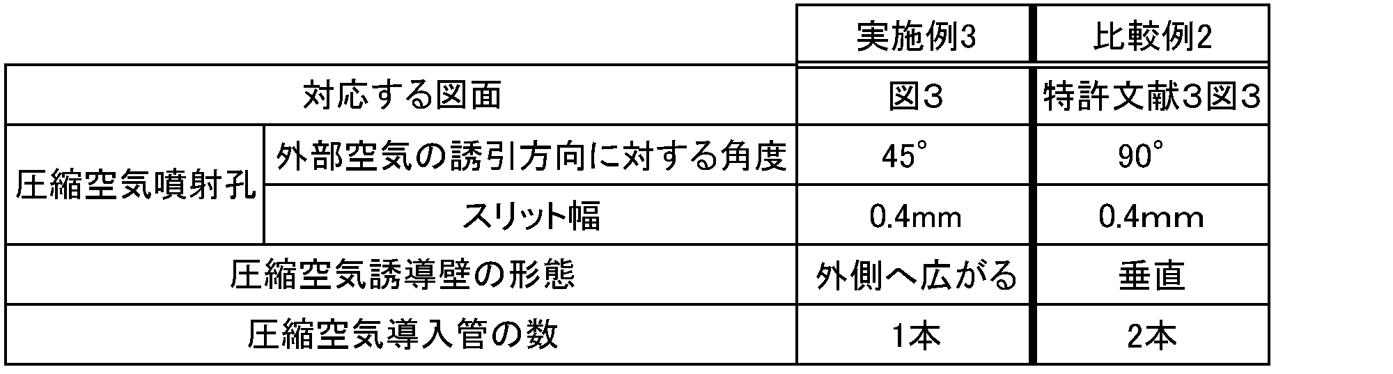
(2)実験方法
実施例3および比較例2に係るバグフィルター用空気増幅システムの圧縮空気導入管を用いて、前記実験例1と同様の方法により空気増幅部への圧縮空気流入量と、増幅空気排出口からの流出空気量とを測定した。また、空気増幅部への圧縮空気の流入量の理論値を前記式(1)~(3)に基づいて算出し、算出した流入量(理論値)と測定した圧縮空気流入量とから、流入効率を算出した。また、測定した圧縮空気流入量と流出空気量から、空気増幅効率(流出空気量/圧縮空気流入量)を算出した。なお、実験は、それぞれの値が平衡となった時点で終了した。
実施例3および比較例2に係るバグフィルター用空気増幅システムの圧縮空気導入管を用いて、前記実験例1と同様の方法により空気増幅部への圧縮空気流入量と、増幅空気排出口からの流出空気量とを測定した。また、空気増幅部への圧縮空気の流入量の理論値を前記式(1)~(3)に基づいて算出し、算出した流入量(理論値)と測定した圧縮空気流入量とから、流入効率を算出した。また、測定した圧縮空気流入量と流出空気量から、空気増幅効率(流出空気量/圧縮空気流入量)を算出した。なお、実験は、それぞれの値が平衡となった時点で終了した。
(3)結果
結果を下記の表4に示す。
結果を下記の表4に示す。

表4の結果に示す通り、従来品である比較例2と比べ、実施例3に係るバグフィルター用空気増幅システムを用いた場合の流出空気量は、0.40kg/secから0.48kg/secへと20%も増加していた。
また、従来品である比較例2と比べ、実施例3に係るバグフィルター用空気増幅システムを用いた場合の流入効率も、81%から91%へと増加していた。この結果から、本発明に係るバグフィルター用空気増幅システムでは、圧縮空気導入管が1本であるにも関わらず、圧縮空気導入管が2本の従来品に比べ、空気増幅率のみならず、圧縮空気の流入効率までも優位に増加させることが確認できた。即ち、本発明に係るバグフィルター用空気増幅システムは、従来品に比べ、より少ない圧縮空気で高い空気増幅効果を実現できることが示された。
<実験例3>
実験例3では、バグフィルター用空気増幅装置の各部での形態の違い、流入空気圧力の違い、噴射時間および噴射間隔の違いによる、増幅空気排出口における風速の変化について検討した。具体的には、本発明に係るバグフィルター用空気増幅装置の例として、図3に示す第2実施形態、従来のバグフィルター用空気増幅装置の例として、特許文献3の図3に示す装置を用いて、増幅空気排出口における風速を比較した。なお、実施例4および比較例3の装置としては、前記実験例2で用いた実施例3および比較例2とそれぞれ同一のものを用いた。
実験例3では、バグフィルター用空気増幅装置の各部での形態の違い、流入空気圧力の違い、噴射時間および噴射間隔の違いによる、増幅空気排出口における風速の変化について検討した。具体的には、本発明に係るバグフィルター用空気増幅装置の例として、図3に示す第2実施形態、従来のバグフィルター用空気増幅装置の例として、特許文献3の図3に示す装置を用いて、増幅空気排出口における風速を比較した。なお、実施例4および比較例3の装置としては、前記実験例2で用いた実施例3および比較例2とそれぞれ同一のものを用いた。
(1)実験方法
実施例4および比較例3に係るバグフィルター用空気増幅システムの圧縮空気導入管に、それぞれ下記の表5に示す圧力の圧縮空気を、それぞれ下記の表5に示す噴射時間および噴射間隔で噴射し、増幅空気排出口における風速を測定した。
実施例4および比較例3に係るバグフィルター用空気増幅システムの圧縮空気導入管に、それぞれ下記の表5に示す圧力の圧縮空気を、それぞれ下記の表5に示す噴射時間および噴射間隔で噴射し、増幅空気排出口における風速を測定した。
(2)結果
増幅空気排出口における風速の結果を下記の表5に示す。
増幅空気排出口における風速の結果を下記の表5に示す。

表5に示す通り、従来品である比較例3と比べ、実施例4に係るバグフィルター用空気増幅システムを用いた場合、流入空気圧力の違い、噴射時間および噴射間隔の違いに関わらず、増幅空気排出口における風速が増加することが確認できた。
以上説明した実験例1~3は、いずれも装置1台での結果である。実際の現場においては、1レーンに装置を8~9台連ねて配置する場合が多いため、従来品と本発明品では、本実験例の結果よりも、大きな差が生じると考えられる。即ち、本発明に係るバグフィルター用空気増幅システムを用いれば、1レーンに装置を8~9台連ねる実際の現場においても、非常に高い空気増幅効率が実現でき、その結果、フィルターの逆洗浄効果を向上させることができると考えられる。
また、本発明に係るバグフィルター用空気増幅システムは、従来品に比べて非常に高い空気増幅効率を実現できるため、従来では十分に逆洗浄効果を得ることができなかったような大きい(長い)バグフィルターにも、好適に用いることができると考えられる。
1 バグフィルター用空気増幅装置
11 空気増幅部
111 R状傾斜面
112 外部空気誘引口
113 増幅空気排出口
114 側壁
12 圧縮空気導入部
121 圧縮空気導入口
122 圧縮空気噴射孔
123 圧縮空気誘導壁
10 バグフィルター用空気増幅システム
2 圧縮空気導入管
3 固定手段
4 圧縮空気誘導板
11 空気増幅部
111 R状傾斜面
112 外部空気誘引口
113 増幅空気排出口
114 側壁
12 圧縮空気導入部
121 圧縮空気導入口
122 圧縮空気噴射孔
123 圧縮空気誘導壁
10 バグフィルター用空気増幅システム
2 圧縮空気導入管
3 固定手段
4 圧縮空気誘導板
Claims (13)
- バグフィルターの逆洗に用いる空気増幅装置であって、
外側へ向かって広がるR状傾斜面と、該R状傾斜面に連設して外部の空気を誘引する外部空気誘引口と、増幅された空気を排出する増幅空気排出口と、前記外部空気誘引口から前記増幅空気排出口へ渡って設けられた筒状の側壁と、が備えられた空気増幅部と、
圧縮された空気を導入する圧縮空気導入口と、圧縮空気を前記空気増幅部へ噴射する圧縮空気噴射孔と、前記圧縮空気導入口から導入された圧縮空気を前記圧縮空気噴射孔へ誘導する湾曲状の圧縮空気誘導壁と、が備えられた圧縮空気導入部と、
を少なくとも備え、
前記圧縮空気噴射孔は、前記R状傾斜面に沿って前記外部空気誘引口に設けられたバグフィルター用空気増幅装置。 - 前記R状傾斜面は、前記圧縮空気誘導壁に覆われた状態である請求項1記載のバグフィルター用空気増幅装置。
- 前記圧縮空気導入口の中心が、前記圧縮空気誘導壁の湾曲の頂点よりも外側に位置する請求項1または2に記載のバグフィルター用空気増幅装置
- 前記増幅空気排出口の断面面積は、前記外部空気誘引口の断面面積より広い請求項1から3のいずれか一項に記載のバグフィルター用空気増幅装置。
- 前記圧縮空気噴射孔から噴射される圧縮空気によるコアンダ効果が少なくとも持続される部位において、前記側壁が外側へ広がる請求項4記載のバグフィルター用空気増幅装置。
- 前記圧縮空気噴射孔は、前記圧縮空気誘導壁と、前記R状傾斜面との間隙で形成される請求項1から5のいずれか一項に記載のバグフィルター用空気増幅装置。
- 前記圧縮空気誘導壁の内壁面には、前記R状傾斜面へ向けて凸部が形成された請求項6記載のバグフィルター用空気増幅装置
- 前記凸部は、圧縮空気の流動方向に沿って設けられた請求項7記載のバグフィルター用空気増幅装置。
- バグフィルターの逆洗に用いる空気増幅システムであって、
請求項1から8のいずれか一項に記載の空気増幅装置と、
該空気増幅装置の前記圧縮空気導入部へ圧縮空気を導入する圧縮空気導入管と、
を少なくとも備えたバグフィルター用空気増幅システム。 - 前記圧縮空気導入部の前記圧縮空気導入管との接続面と、前記圧縮空気導入管の前記圧縮空気導入部との接続面とが、互いに平行に形成された請求項9記載のバグフィルター用空気増幅システム。
- 前記圧縮空気導入部と前記圧縮空気導入管との接続部が、パッキンにてシールされた請求項9または10に記載のバグフィルター用空気増幅システム。
- 前記接続部に、前記圧縮空気導入管から前記圧縮空気導入部への圧縮空気の導入を誘導する圧縮空気誘導板が備えられた請求項9から11のいずれか一項に記載のバグフィルター用空気増幅システム。
- 前記空気増幅装置を固定する固定手段が備えられた請求項9から12のいずれか一項に記載のバグフィルター用空気増幅システム。
Priority Applications (1)
| Application Number | Priority Date | Filing Date | Title |
|---|---|---|---|
| JP2014529481A JP6111485B2 (ja) | 2012-08-07 | 2013-08-05 | バグフィルター用空気増幅装置および該バグフィルター用空気増幅装置を用いたバグフィルター用空気増幅システム |
Applications Claiming Priority (2)
| Application Number | Priority Date | Filing Date | Title |
|---|---|---|---|
| JP2012174940 | 2012-08-07 | ||
| JP2012-174940 | 2012-08-07 |
Publications (1)
| Publication Number | Publication Date |
|---|---|
| WO2014024817A1 true WO2014024817A1 (ja) | 2014-02-13 |
Family
ID=50068043
Family Applications (1)
| Application Number | Title | Priority Date | Filing Date |
|---|---|---|---|
| PCT/JP2013/071106 Ceased WO2014024817A1 (ja) | 2012-08-07 | 2013-08-05 | バグフィルター用空気増幅装置および該バグフィルター用空気増幅装置を用いたバグフィルター用空気増幅システム |
Country Status (3)
| Country | Link |
|---|---|
| JP (4) | JP6111485B2 (ja) |
| TW (1) | TW201420168A (ja) |
| WO (1) | WO2014024817A1 (ja) |
Cited By (1)
| Publication number | Priority date | Publication date | Assignee | Title |
|---|---|---|---|---|
| JP2017522183A (ja) * | 2014-07-25 | 2017-08-10 | チョ グァンソプCHO, Kwang−Sup | 互いに分離された二つの制御バルブと圧縮空気管を有する集塵機バグフィルター脱塵システム |
Families Citing this family (1)
| Publication number | Priority date | Publication date | Assignee | Title |
|---|---|---|---|---|
| CN110840102B (zh) * | 2019-12-09 | 2021-07-02 | 江西白莲智能科技集团有限公司 | 一种图书馆用防尘书架 |
Citations (3)
| Publication number | Priority date | Publication date | Assignee | Title |
|---|---|---|---|---|
| JPH0640350U (ja) * | 1992-11-05 | 1994-05-27 | 三菱重工業株式会社 | エアクリーナ |
| JP2008115847A (ja) * | 2006-11-01 | 2008-05-22 | Kwang Sup Cho | 空気増幅器を利用した圧縮空気噴射装置 |
| JP2012036898A (ja) * | 2010-08-06 | 2012-02-23 | Dyson Technology Ltd | ファン組立体 |
Family Cites Families (18)
| Publication number | Priority date | Publication date | Assignee | Title |
|---|---|---|---|---|
| US3216653A (en) * | 1962-07-09 | 1965-11-09 | Bertin & Cie | Ejectors and piping systems operating with a divergent fluid wall |
| US3806039A (en) * | 1972-03-14 | 1974-04-23 | Src Lab | Coanda type nozzle with discontinuous slot |
| US3743186A (en) * | 1972-03-14 | 1973-07-03 | Src Lab | Air gun |
| CA981918A (en) * | 1972-11-30 | 1976-01-20 | Lester W. Throndson | Compound ejector for high energy flow fluid |
| US3801020A (en) * | 1972-12-19 | 1974-04-02 | Src Lab | Air gun and nozzle therefor |
| DE2332031B2 (de) * | 1973-06-23 | 1979-03-22 | Intensiv-Filter Gmbh & Co Kg, 5602 Langenberg | Reinigungsvorrichtung für Gasfilterelemente |
| CH593092A5 (ja) * | 1974-05-06 | 1977-11-30 | Intensiv Filter Gmbh | |
| JPS51149483U (ja) * | 1975-05-23 | 1976-11-30 | ||
| DK140426B (da) * | 1976-11-01 | 1979-08-27 | Arborg O J M | Fremdriftsdyse til transportmidler i luft eller vand. |
| DE3005146C2 (de) * | 1980-02-12 | 1983-04-07 | Intensiv-Filter Gmbh & Co Kg, 5620 Velbert | Druckgasanschluß bei Staubgasfiltern |
| DE19849639C1 (de) * | 1998-10-28 | 2000-02-10 | Intensiv Filter Gmbh | Coanda-Injektor und Druckgasleitung zum Anschluß eines solchen |
| EP1029576A1 (de) * | 1999-02-18 | 2000-08-23 | Jetclean GmbH | Vorrichtung zur Reinigung eines Filters |
| JP2001025631A (ja) * | 1999-07-15 | 2001-01-30 | Kanken:Kk | ガス浄化装置 |
| KR100730305B1 (ko) * | 2007-03-09 | 2007-06-19 | 주식회사 삼탑엔지니어링 | 펄스 에어 가속 집진기 |
| DE102007047276A1 (de) * | 2007-10-02 | 2009-04-09 | Intensiv-Filter Gmbh & Co. Kg | Reinigungsvorrichtung für ein Staubfilter |
| WO2011118862A1 (ko) * | 2010-03-24 | 2011-09-29 | 한국에너지기술연구원 | 이중 원주형 슬릿 탈진공기 분사노즐 및 이를 이용한 여과집진장치 탈진시스템 |
| JP5574548B2 (ja) * | 2011-11-01 | 2014-08-20 | 東北電機鉄工株式会社 | コアンダインジェクター |
| JP5498536B2 (ja) * | 2012-07-03 | 2014-05-21 | 株式会社トータルビジネスソリューション | バグフィルター清掃用コアンダインジェクター |
-
2013
- 2013-08-05 JP JP2014529481A patent/JP6111485B2/ja active Active
- 2013-08-05 WO PCT/JP2013/071106 patent/WO2014024817A1/ja not_active Ceased
- 2013-08-06 TW TW102128032A patent/TW201420168A/zh unknown
-
2017
- 2017-02-22 JP JP2017031534A patent/JP6290477B2/ja active Active
- 2017-02-22 JP JP2017031533A patent/JP6290476B2/ja active Active
-
2018
- 2018-02-05 JP JP2018018189A patent/JP6499779B2/ja active Active
Patent Citations (3)
| Publication number | Priority date | Publication date | Assignee | Title |
|---|---|---|---|---|
| JPH0640350U (ja) * | 1992-11-05 | 1994-05-27 | 三菱重工業株式会社 | エアクリーナ |
| JP2008115847A (ja) * | 2006-11-01 | 2008-05-22 | Kwang Sup Cho | 空気増幅器を利用した圧縮空気噴射装置 |
| JP2012036898A (ja) * | 2010-08-06 | 2012-02-23 | Dyson Technology Ltd | ファン組立体 |
Cited By (1)
| Publication number | Priority date | Publication date | Assignee | Title |
|---|---|---|---|---|
| JP2017522183A (ja) * | 2014-07-25 | 2017-08-10 | チョ グァンソプCHO, Kwang−Sup | 互いに分離された二つの制御バルブと圧縮空気管を有する集塵機バグフィルター脱塵システム |
Also Published As
| Publication number | Publication date |
|---|---|
| JP2017100134A (ja) | 2017-06-08 |
| TW201420168A (zh) | 2014-06-01 |
| JP2018065140A (ja) | 2018-04-26 |
| JP6499779B2 (ja) | 2019-04-10 |
| JP2017087212A (ja) | 2017-05-25 |
| JP6290477B2 (ja) | 2018-03-07 |
| JP6290476B2 (ja) | 2018-03-07 |
| JP6111485B2 (ja) | 2017-04-12 |
| JPWO2014024817A1 (ja) | 2016-07-25 |
Similar Documents
| Publication | Publication Date | Title |
|---|---|---|
| US7998253B2 (en) | Airflow reducing and redirecting arrangement for industrial baghouse | |
| JP4413241B2 (ja) | 空気増幅器を利用した圧縮空気噴射装置 | |
| JP2013519824A (ja) | ガスタービンの吸気システムのコイル構造及びその方法 | |
| JP6499779B2 (ja) | バグフィルター用空気増幅装置および該バグフィルター用空気増幅装置を用いたバグフィルター用空気増幅システム | |
| JP6155534B2 (ja) | 圧縮空気噴射装置 | |
| US5030261A (en) | Two stage transition input section for dust collectors | |
| KR101471809B1 (ko) | 서로 분리된 2개의 제어밸브와 압축공기관을 갖는 집진기 백필터 탈진 시스템 | |
| CN104857778A (zh) | 织物过滤器系统及用于清洁其的方法 | |
| JP6607880B2 (ja) | 圧縮空気噴射装置 | |
| KR101643574B1 (ko) | 백필터 탈진용 분사노즐 | |
| CN202909592U (zh) | 空压机进气系统 | |
| EP3423191B1 (en) | Gas dedusting filter apparatus and process | |
| KR101102453B1 (ko) | 필터백 청소용 노즐 | |
| KR20150015194A (ko) | 디퓨져가 내장된 백필터 | |
| JP2014171973A (ja) | 圧縮空気パルス射出用配管及びバグフィルター用空気増幅システム | |
| KR20120083258A (ko) | 공기증폭기를 이용한 압축공기 분사장치 | |
| JP5969686B2 (ja) | バグフィルター用空気増幅装置および該バグフィルター用空気増幅装置を用いたバグフィルター用空気増幅システム | |
| KR200472211Y1 (ko) | 대용량 압축공기 분사장치 | |
| JP5130549B2 (ja) | フィルタ、冷却用噴射部材および冷却風噴射方法 | |
| KR101577338B1 (ko) | 집진 장치 | |
| KR20150047882A (ko) | 관성형 공기 필터 및 이를 구비한 가스터빈 시스템 | |
| CN207342375U (zh) | 一种用于袋式除尘器的脉冲引射等压喷吹装置 | |
| CN104107597A (zh) | 一种提高分气箱防腐能力的除尘器及其制造方法 | |
| CN203971620U (zh) | 一种提高分气箱防腐能力的除尘器 | |
| JP3208536U (ja) | エアゾールを用いた簡易集塵装置 |
Legal Events
| Date | Code | Title | Description |
|---|---|---|---|
| 121 | Ep: the epo has been informed by wipo that ep was designated in this application |
Ref document number: 13827711 Country of ref document: EP Kind code of ref document: A1 |
|
| ENP | Entry into the national phase |
Ref document number: 2014529481 Country of ref document: JP Kind code of ref document: A |
|
| NENP | Non-entry into the national phase |
Ref country code: DE |
|
| 122 | Ep: pct application non-entry in european phase |
Ref document number: 13827711 Country of ref document: EP Kind code of ref document: A1 |