WO2014024385A1 - Vehicle lamp fitting - Google Patents
Vehicle lamp fitting Download PDFInfo
- Publication number
- WO2014024385A1 WO2014024385A1 PCT/JP2013/004385 JP2013004385W WO2014024385A1 WO 2014024385 A1 WO2014024385 A1 WO 2014024385A1 JP 2013004385 W JP2013004385 W JP 2013004385W WO 2014024385 A1 WO2014024385 A1 WO 2014024385A1
- Authority
- WO
- WIPO (PCT)
- Prior art keywords
- laser light
- light source
- distribution pattern
- vehicle
- unit
- Prior art date
Links
Images


Classifications
-
- F—MECHANICAL ENGINEERING; LIGHTING; HEATING; WEAPONS; BLASTING
- F21—LIGHTING
- F21S—NON-PORTABLE LIGHTING DEVICES; SYSTEMS THEREOF; VEHICLE LIGHTING DEVICES SPECIALLY ADAPTED FOR VEHICLE EXTERIORS
- F21S41/00—Illuminating devices specially adapted for vehicle exteriors, e.g. headlamps
- F21S41/30—Illuminating devices specially adapted for vehicle exteriors, e.g. headlamps characterised by reflectors
- F21S41/32—Optical layout thereof
- F21S41/36—Combinations of two or more separate reflectors
- F21S41/365—Combinations of two or more separate reflectors successively reflecting the light
-
- B—PERFORMING OPERATIONS; TRANSPORTING
- B60—VEHICLES IN GENERAL
- B60Q—ARRANGEMENT OF SIGNALLING OR LIGHTING DEVICES, THE MOUNTING OR SUPPORTING THEREOF OR CIRCUITS THEREFOR, FOR VEHICLES IN GENERAL
- B60Q1/00—Arrangement of optical signalling or lighting devices, the mounting or supporting thereof or circuits therefor
- B60Q1/0017—Devices integrating an element dedicated to another function
- B60Q1/0023—Devices integrating an element dedicated to another function the element being a sensor, e.g. distance sensor, camera
-
- B—PERFORMING OPERATIONS; TRANSPORTING
- B60—VEHICLES IN GENERAL
- B60Q—ARRANGEMENT OF SIGNALLING OR LIGHTING DEVICES, THE MOUNTING OR SUPPORTING THEREOF OR CIRCUITS THEREFOR, FOR VEHICLES IN GENERAL
- B60Q1/00—Arrangement of optical signalling or lighting devices, the mounting or supporting thereof or circuits therefor
- B60Q1/02—Arrangement of optical signalling or lighting devices, the mounting or supporting thereof or circuits therefor the devices being primarily intended to illuminate the way ahead or to illuminate other areas of way or environments
- B60Q1/04—Arrangement of optical signalling or lighting devices, the mounting or supporting thereof or circuits therefor the devices being primarily intended to illuminate the way ahead or to illuminate other areas of way or environments the devices being headlights
- B60Q1/14—Arrangement of optical signalling or lighting devices, the mounting or supporting thereof or circuits therefor the devices being primarily intended to illuminate the way ahead or to illuminate other areas of way or environments the devices being headlights having dimming means
- B60Q1/1415—Dimming circuits
- B60Q1/1423—Automatic dimming circuits, i.e. switching between high beam and low beam due to change of ambient light or light level in road traffic
- B60Q1/143—Automatic dimming circuits, i.e. switching between high beam and low beam due to change of ambient light or light level in road traffic combined with another condition, e.g. using vehicle recognition from camera images or activation of wipers
-
- B—PERFORMING OPERATIONS; TRANSPORTING
- B60—VEHICLES IN GENERAL
- B60Q—ARRANGEMENT OF SIGNALLING OR LIGHTING DEVICES, THE MOUNTING OR SUPPORTING THEREOF OR CIRCUITS THEREFOR, FOR VEHICLES IN GENERAL
- B60Q1/00—Arrangement of optical signalling or lighting devices, the mounting or supporting thereof or circuits therefor
- B60Q1/02—Arrangement of optical signalling or lighting devices, the mounting or supporting thereof or circuits therefor the devices being primarily intended to illuminate the way ahead or to illuminate other areas of way or environments
- B60Q1/24—Arrangement of optical signalling or lighting devices, the mounting or supporting thereof or circuits therefor the devices being primarily intended to illuminate the way ahead or to illuminate other areas of way or environments for lighting other areas than only the way ahead
- B60Q1/245—Searchlights, e.g. adjustable from within the vehicle
-
- B—PERFORMING OPERATIONS; TRANSPORTING
- B60—VEHICLES IN GENERAL
- B60Q—ARRANGEMENT OF SIGNALLING OR LIGHTING DEVICES, THE MOUNTING OR SUPPORTING THEREOF OR CIRCUITS THEREFOR, FOR VEHICLES IN GENERAL
- B60Q11/00—Arrangement of monitoring devices for devices provided for in groups B60Q1/00 - B60Q9/00
- B60Q11/005—Arrangement of monitoring devices for devices provided for in groups B60Q1/00 - B60Q9/00 for lighting devices, e.g. indicating if lamps are burning or not
-
- F—MECHANICAL ENGINEERING; LIGHTING; HEATING; WEAPONS; BLASTING
- F21—LIGHTING
- F21S—NON-PORTABLE LIGHTING DEVICES; SYSTEMS THEREOF; VEHICLE LIGHTING DEVICES SPECIALLY ADAPTED FOR VEHICLE EXTERIORS
- F21S41/00—Illuminating devices specially adapted for vehicle exteriors, e.g. headlamps
- F21S41/10—Illuminating devices specially adapted for vehicle exteriors, e.g. headlamps characterised by the light source
- F21S41/12—Illuminating devices specially adapted for vehicle exteriors, e.g. headlamps characterised by the light source characterised by the type of emitted light
- F21S41/13—Ultraviolet light; Infrared light
-
- F—MECHANICAL ENGINEERING; LIGHTING; HEATING; WEAPONS; BLASTING
- F21—LIGHTING
- F21S—NON-PORTABLE LIGHTING DEVICES; SYSTEMS THEREOF; VEHICLE LIGHTING DEVICES SPECIALLY ADAPTED FOR VEHICLE EXTERIORS
- F21S41/00—Illuminating devices specially adapted for vehicle exteriors, e.g. headlamps
- F21S41/10—Illuminating devices specially adapted for vehicle exteriors, e.g. headlamps characterised by the light source
- F21S41/14—Illuminating devices specially adapted for vehicle exteriors, e.g. headlamps characterised by the light source characterised by the type of light source
- F21S41/16—Laser light sources
-
- F—MECHANICAL ENGINEERING; LIGHTING; HEATING; WEAPONS; BLASTING
- F21—LIGHTING
- F21S—NON-PORTABLE LIGHTING DEVICES; SYSTEMS THEREOF; VEHICLE LIGHTING DEVICES SPECIALLY ADAPTED FOR VEHICLE EXTERIORS
- F21S41/00—Illuminating devices specially adapted for vehicle exteriors, e.g. headlamps
- F21S41/10—Illuminating devices specially adapted for vehicle exteriors, e.g. headlamps characterised by the light source
- F21S41/14—Illuminating devices specially adapted for vehicle exteriors, e.g. headlamps characterised by the light source characterised by the type of light source
- F21S41/176—Light sources where the light is generated by photoluminescent material spaced from a primary light generating element
-
- F—MECHANICAL ENGINEERING; LIGHTING; HEATING; WEAPONS; BLASTING
- F21—LIGHTING
- F21S—NON-PORTABLE LIGHTING DEVICES; SYSTEMS THEREOF; VEHICLE LIGHTING DEVICES SPECIALLY ADAPTED FOR VEHICLE EXTERIORS
- F21S41/00—Illuminating devices specially adapted for vehicle exteriors, e.g. headlamps
- F21S41/30—Illuminating devices specially adapted for vehicle exteriors, e.g. headlamps characterised by reflectors
- F21S41/32—Optical layout thereof
- F21S41/321—Optical layout thereof the reflector being a surface of revolution or a planar surface, e.g. truncated
-
- F—MECHANICAL ENGINEERING; LIGHTING; HEATING; WEAPONS; BLASTING
- F21—LIGHTING
- F21S—NON-PORTABLE LIGHTING DEVICES; SYSTEMS THEREOF; VEHICLE LIGHTING DEVICES SPECIALLY ADAPTED FOR VEHICLE EXTERIORS
- F21S41/00—Illuminating devices specially adapted for vehicle exteriors, e.g. headlamps
- F21S41/60—Illuminating devices specially adapted for vehicle exteriors, e.g. headlamps characterised by a variable light distribution
- F21S41/65—Illuminating devices specially adapted for vehicle exteriors, e.g. headlamps characterised by a variable light distribution by acting on light sources
- F21S41/663—Illuminating devices specially adapted for vehicle exteriors, e.g. headlamps characterised by a variable light distribution by acting on light sources by switching light sources
-
- F—MECHANICAL ENGINEERING; LIGHTING; HEATING; WEAPONS; BLASTING
- F21—LIGHTING
- F21S—NON-PORTABLE LIGHTING DEVICES; SYSTEMS THEREOF; VEHICLE LIGHTING DEVICES SPECIALLY ADAPTED FOR VEHICLE EXTERIORS
- F21S41/00—Illuminating devices specially adapted for vehicle exteriors, e.g. headlamps
- F21S41/60—Illuminating devices specially adapted for vehicle exteriors, e.g. headlamps characterised by a variable light distribution
- F21S41/67—Illuminating devices specially adapted for vehicle exteriors, e.g. headlamps characterised by a variable light distribution by acting on reflectors
- F21S41/675—Illuminating devices specially adapted for vehicle exteriors, e.g. headlamps characterised by a variable light distribution by acting on reflectors by moving reflectors
-
- F—MECHANICAL ENGINEERING; LIGHTING; HEATING; WEAPONS; BLASTING
- F21—LIGHTING
- F21S—NON-PORTABLE LIGHTING DEVICES; SYSTEMS THEREOF; VEHICLE LIGHTING DEVICES SPECIALLY ADAPTED FOR VEHICLE EXTERIORS
- F21S45/00—Arrangements within vehicle lighting devices specially adapted for vehicle exteriors, for purposes other than emission or distribution of light
- F21S45/70—Prevention of harmful light leakage
-
- B—PERFORMING OPERATIONS; TRANSPORTING
- B60—VEHICLES IN GENERAL
- B60Q—ARRANGEMENT OF SIGNALLING OR LIGHTING DEVICES, THE MOUNTING OR SUPPORTING THEREOF OR CIRCUITS THEREFOR, FOR VEHICLES IN GENERAL
- B60Q2300/00—Indexing codes for automatically adjustable headlamps or automatically dimmable headlamps
- B60Q2300/40—Indexing codes relating to other road users or special conditions
- B60Q2300/45—Special conditions, e.g. pedestrians, road signs or potential dangers
Definitions
- the present invention relates to a vehicle lamp, and in particular to a vehicle lamp used for a vehicle such as a car.
- Patent Document 1 discloses a vehicular headlamp provided with a semiconductor laser for emitting a laser beam and a light emitting unit that includes a phosphor and emits a laser beam upon receiving the laser beam.
- laser light blue-violet
- the light emitter is a silicone resin containing blue, green and red phosphors, and receives blue-violet laser light to generate white light.
- the white light generated by the light emitter is reflected forward of the lamp by the reflector.
- Vehicle lamps have a function to improve the driver's visibility by irradiating the front of the vehicle with light, but improve the driver's visibility to pedestrians, falling objects, buildings, etc. Improvements in performance, such as the reduction of glare given to drivers of other vehicles, are always required of vehicle lamps. Such requirements are no exception for vehicle lamps using laser light sources.
- the present invention has been made in view of these problems, and an object thereof is to provide a technique for improving the performance of a vehicular lamp.
- one mode of the present invention is a lamp for vehicles.
- the vehicular lamp scans a laser light source, a laser beam emitted from the laser light source, and a scanning unit that forms a predetermined visible light distribution pattern, and an obstacle detection that detects an obstacle in front of the vehicle.
- a control unit configured to adjust the intensity of the laser beam when irradiating the obstacle existing region based on the detection result of the obstacle detection unit.
- the obstacle detection unit may include an infrared light source and an infrared detection unit, and the scanning unit may scan the infrared light emitted from the infrared light source together with the laser light. According to this aspect, it is possible to suppress the increase in the manufacturing cost and the number of parts of the vehicle lamp and the increase in the size due to the provision of the obstacle detection unit.
- control unit is configured to irradiate the central portion of the visible light distribution pattern with the intensity of the laser light when the peripheral portion of the visible light distribution pattern is irradiated. It may be lower than the intensity of the laser beam. According to this aspect, it is possible to moderate the change in illuminance at the light and dark boundary of the visible light distribution pattern, so it is possible to reduce the visual discomfort which is given to the driver and the pedestrian.
- FIG. 1 is a vertical cross-sectional view showing a schematic structure of a vehicular lamp according to a first embodiment. It is a side view showing a schematic structure of a light source unit. It is a schematic perspective view of a scanning part when observed from a lamp front side.
- FIG. 6 is a view showing an example of a visible light distribution pattern formed by the vehicle lamp according to the first embodiment. It is a functional block diagram explaining a control unit. 6 (A) and 6 (B) are schematic diagrams for demonstrating the laser beam irradiation control which the vehicle lamp which concerns on Embodiment 1 implements.
- FIG. 1 is a vertical cross-sectional view showing a schematic structure of a vehicular lamp according to a first embodiment. It is a side view showing a schematic structure of a light source unit. It is a schematic perspective view of a scanning part when observed from a lamp front side.
- FIG. 6 is a view showing an example of a visible light distribution pattern formed by the vehicle lamp according to the first embodiment. It
- FIG. 7 (A) and 7 (B) are schematic diagrams for demonstrating laser-beam irradiation control which the vehicle lamp which concerns on Embodiment 2 implements.
- FIG. FIG. 8A and FIG. 8B are schematic views for explaining laser light irradiation control performed by the vehicle lamp according to the third embodiment.
- FIGS. 9A to 9C are schematic views for explaining laser light irradiation control performed by the vehicle lamp according to the fourth embodiment.
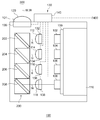
- FIG. 1 is a vertical cross-sectional view showing a schematic structure of the vehicle lamp according to the first embodiment. Note that FIG. 1 illustrates a state in which the inside of the light source unit 100 is seen through. Further, illustration of the permanent magnets 312 and 314 of the scanning unit 300 is omitted.
- the vehicular lamp according to the present embodiment is, for example, a vehicular headlamp apparatus having a pair of headlamp units disposed on the left and right of the front of the vehicle. Since the pair of headlight units have substantially the same configuration, FIG. 1 shows the configuration of the left or right headlight unit as the vehicular lamp 1.
- the vehicular lamp 1 includes a lamp body 2 having an opening on the front side of the vehicle, and a translucent cover 4 that covers the opening of the lamp body 2.
- the translucent cover 4 is formed of a translucent resin, glass, or the like.
- the support plate 6, the light source unit 100, the scanning unit 300, and the control unit 400 are accommodated in the lamp chamber 3 formed by the lamp body 2 and the light transmitting cover 4.
- the light source unit 100 and the scanning unit 300 are supported by the support plate 6 at a predetermined position in the lamp chamber 3.
- the support plate 6 is connected at its corners to the lamp body 2 by the aiming screw 8.
- the light source unit 100 includes a first laser light source 102, a second laser light source 104, a third laser light source 106, a fourth laser light source 108, a heat sink 110, a light collecting unit 200, and the like.
- the light source unit 100 is fixed to the front surface of the support plate 6 such that the heat sink 110 is in contact with the support plate 6.
- the internal structure of the light source unit 100 will be described in detail later.
- the scanning unit 300 has a reflecting mirror 318. The structure of the scanning unit 300 will be described in detail later.
- the scanning unit 300 has a positional relationship with the light source unit 100 determined so as to reflect the laser light emitted from the light source unit 100 to the front of the lamp, and the projecting portion 10 protrudes from the front surface of the support plate 6 to the lamp front side. It is fixed.
- the protrusion 10 includes a pivot mechanism 10 a, and the scanning unit 300 is supported by the protrusion 10 via the pivot mechanism 10 a.
- the protrusion 10 includes a support actuator 10 b having a rod and a motor that extends and retracts the rod in the front-rear direction of the lamp. The tip of the rod is connected to the scanning unit 300.
- the projecting portion 10 can swing the scanning portion 300 about the pivot mechanism 10a by expanding and contracting the rod, whereby the inclination angle (pitch angle) of the scanning portion 300 in the vertical direction can be adjusted.
- the supporting actuator 10b is connected to the control unit 400, and its drive is controlled by an actuator control unit 408 (see FIG. 5) of the control unit 400 described later.
- the control unit 400 is fixed to the lamp body 2 on the lamp rear side with respect to the support plate 6. The position where the control unit 400 is provided is not particularly limited.
- the vehicular lamp 1 can adjust the optical axis in the horizontal direction and the vertical direction by rotating the aiming screw 8 to adjust the posture of the support plate 6.
- an extension member 12 having an opening that allows the light reflected by the scanning unit 300 to travel forward of the lamp is provided. Subsequently, the configuration of each part constituting the vehicular lamp 1 will be described in detail.
- FIG. 2 is a side view showing a schematic structure of the light source unit. Note that FIG. 2 illustrates a state in which the inside of the light source unit 100 is seen through.
- the light source unit 100 includes a first laser light source 102, a second laser light source 104, a third laser light source 106, a fourth laser light source 108, a heat sink 110, a first lens 112, a second lens 114, a third lens 116, and a fourth lens. It has 118, the 5th lens 120, and condensing part 200 grade.
- the first laser light source 102 is configured by a red laser diode and emits red laser light R.
- the second laser light source 104 is constituted by a green laser diode and emits green laser light G.
- the third laser light source 106 is composed of a blue laser diode and emits blue laser light B.
- the fourth laser light source 108 (infrared light source) is composed of an infrared laser diode and emits infrared laser light IR (infrared light).
- the first to fourth laser light sources 102 to 108 are mounted on a common substrate 109. Each light source may have a laser device other than a laser diode.
- the infrared light source may be a light source other than the laser light source.
- the first laser light source 102, the second laser light source 104, the third laser light source 106, and the fourth laser light source 108 are disposed such that their respective laser light emitting surfaces face the lamp front side and the substrate 109 faces the lamp back side.
- the heat sink 110 is formed of a material having high thermal conductivity such as aluminum so that the heat generated by each laser light source can be efficiently recovered.
- the surface on the lamp rear side of the heat sink 110 is in contact with the support plate 6 (see FIG. 1).
- Each laser light source dissipates heat via the substrate 109, the heat sink 110 and the support plate 6.
- the first lens 112, the second lens 114, the third lens 116, the fourth lens 118, and the fifth lens 120 are configured by, for example, a collimator lens.
- the first lens 112 is provided on the optical path of the red laser light R between the first laser light source 102 and the light collecting unit 200, and collimates the red laser light R traveling from the first laser light source 102 toward the light collecting unit 200.
- Convert to The second lens 114 is provided on the optical path of the green laser light G between the second laser light source 104 and the light collecting unit 200, and collimates the green laser light G traveling from the second laser light source 104 toward the light collecting unit 200.
- Convert to The third lens 116 is provided on the optical path of the blue laser light B between the third laser light source 106 and the light collecting unit 200, and collimates the blue laser light B traveling from the third laser light source 106 toward the light collecting unit 200. Convert to
- the fourth lens 118 is provided on the optical path of the infrared laser light IR between the fourth laser light source 108 and the light collecting unit 200, and the infrared laser light IR traveling from the fourth laser light source 108 toward the light collecting unit 200 is Convert to collimated light.
- the fifth lens 120 is fitted in the opening 101 provided in the housing of the light source unit 100.
- the fifth lens 120 is provided on the light path of the white laser light W and the infrared laser light IR, which will be described later, between the light collecting unit 200 and the scanning unit 300 (see FIG. 1).
- the white laser light W and the infrared laser light IR traveling to 300 are converted into parallel light.
- the condensing unit 200 generates the white laser light W by aggregating the red laser light R, the green laser light G, and the blue laser light B. In addition, the infrared laser light IR is gathered in the white laser light W.
- the condensing unit 200 includes a first dichroic mirror 202, a second dichroic mirror 204, a third dichroic mirror 206, and a fourth dichroic mirror 208.
- the first dichroic mirror 202 is a mirror that reflects at least red light and transmits blue light, green light and infrared light, and reflects the red laser light R that has passed through the first lens 112 toward the fifth lens 120 Arranged as.
- the second dichroic mirror 204 is a mirror that reflects at least green light and transmits blue light and infrared light, and is arranged to reflect the green laser light G that has passed through the second lens 114 toward the fifth lens 120. Be done.
- the third dichroic mirror 206 is a mirror that reflects at least blue light and transmits infrared light, and is disposed to reflect the blue laser light B that has passed through the third lens 116 toward the fifth lens 120.
- the fourth dichroic mirror 208 is a mirror that reflects at least infrared light, and is arranged to reflect the infrared laser light IR that has passed through the fourth lens 118 toward the fifth lens 120.
- the respective dichroic mirrors have their positional relationship determined so that the optical paths of the laser beams reflected by the respective dichroic mirrors are parallel, and the respective laser beams are collectively incident on the fifth lens 120.
- the first dichroic mirror 202 to the fourth dichroic mirror 208 are arranged such that the regions (reflection points of the laser light) on which the laser light impinges in each dichroic mirror are aligned in a straight line.
- the infrared laser light IR emitted from the fourth laser light source 108 is reflected by the fourth dichroic mirror 208 and travels to the third dichroic mirror 206 side.
- the blue laser light B emitted from the third laser light source 106 is reflected by the third dichroic mirror 206 toward the second dichroic mirror 204, and is superimposed on the infrared laser light IR transmitted through the third dichroic mirror 206.
- the green laser light G emitted from the second laser light source 104 is reflected by the second dichroic mirror 204 toward the first dichroic mirror 202, and the infrared laser light IR and the blue laser light transmitted through the second dichroic mirror 204 It is superimposed on the collective light of B.
- the red laser light R emitted from the first laser light source 102 is reflected toward the fifth lens 120 by the first dichroic mirror 202, and the infrared laser light IR and the blue laser light B transmitted through the first dichroic mirror 202. And the collective light of the green laser light G. As a result, white laser light W including infrared laser light IR is formed.
- the mixed laser beam of the infrared laser beam IR and the white laser beam W passes through the fifth lens 120 and travels toward the scanning unit 300.
- the light source unit 100 has a monitoring unit 130 that monitors emission of each laser beam.
- the monitoring unit 130 includes a first photosensor 132, a second photosensor 134, a third photosensor 136, a fourth photosensor 138, a fifth photosensor 139, and an abnormality determination unit 140.
- the first photosensor 132 measures the intensity of the red laser light R.
- the second photosensor 134 measures the intensity of the green laser light G.
- the third photosensor 136 measures the intensity of the blue laser light B.
- the fourth photosensor 138 measures the intensity of the infrared laser light IR.
- the fifth photosensor 139 measures the intensity of the combined light of the white laser light W and the infrared laser light IR.
- Each photosensor transmits a signal indicating the measured value to the abnormality determination unit 140.
- the abnormality determination unit 140 compares the measurement values of the first photo sensor 132 to the fourth photo sensor 138 with the preset setting range of the irradiation intensity, and determines whether or not the laser light emission abnormality occurs in each laser light source. Determine if In addition, the abnormality determination unit 140 uses the measured value of the fifth photosensor 139 to include the intensity of the white laser light W or the intensity of the combined light of the white laser light W and the infrared laser light IR in a predetermined setting range. It is determined whether the The abnormality determination unit 140 can calculate the intensity of the white laser light W by subtracting the measurement value of the fourth photosensor 138 from the measurement value of the fifth photosensor 139. The abnormality determination unit 140 transmits a signal indicating the determination result to the control unit 400. The abnormality determination unit 140 may be provided in the control unit 400.
- FIG. 3 is a schematic perspective view of the scanning unit when observed from the front side of the lamp.
- the scanning unit 300 is a mechanism for scanning laser light emitted from the first laser light source 102 to the third laser light source 106 to form a predetermined visible light distribution pattern (see FIG. 4).
- the scanning unit 300 scans the front of the vehicle with the infrared laser light IR.
- the scanning unit 300 is formed of, for example, a so-called galvano mirror, and the base 302, the first rotating body 304, the second rotating body 306, the first torsion bar 308, the second torsion bar 310, the permanent magnets 312 and 314, and the terminal portion 316. And a reflecting mirror 318 and the like.
- the base 302 is a frame having an opening 302a at the center, and is fixed to the tip of the projection 10 (see FIG. 1) in a state of being inclined in the front-rear direction of the lamp.
- a terminal portion 316 is provided on the base 302 at a predetermined position.
- the first pivoting body 304 is disposed in the opening 302a.
- the first pivoting body 304 is a frame having an opening 304a at the center, and is pivoted to the left and right (in the vehicle width direction) with respect to the base 302 by the first torsion bar 308 extending from the lamp rear lower side to the lamp front upper side. It is movably supported.
- the second pivoting body 306 is disposed in the opening 304 a of the first pivoting body 304.
- the second pivoting body 306 is a rectangular flat plate, and is rotatably supported vertically (vertically) with respect to the first pivoting body 304 by a second torsion bar 310 extending in the vehicle width direction.
- the second pivoting body 306 pivots left and right together with the first pivoting body 304 when the first pivoting body 304 pivots left and right with the first torsion bar 308 as a pivoting axis.
- a reflecting mirror 318 is provided on the surface of the second rotating body 306 by a method such as plating or vapor deposition.
- the base 302 is provided with a pair of permanent magnets 312 at a position orthogonal to the extending direction of the first torsion bar 308.
- the permanent magnet 312 forms a magnetic field orthogonal to the first torsion bar 308.
- a first coil (not shown) is wired to the first rotating body 304, and the first coil is connected to the control unit 400 via the terminal portion 316.
- the base 302 is provided with a pair of permanent magnets 314 at a position orthogonal to the extending direction of the second torsion bar 310.
- the permanent magnet 314 forms a magnetic field orthogonal to the second torsion bar 310.
- a second coil (not shown) is wired to the second rotating body 306, and the second coil is connected to the control unit 400 via the terminal portion 316.
- the first coil and permanent magnet 312 and the second coil and permanent magnet 314 constitute a scanning actuator 320 (see FIG. 5).
- the drive of the scanning actuator 320 is controlled by an actuator control unit 408 (see FIG. 5) described later.
- the actuator control unit 408 controls the magnitude and direction of the drive voltage flowing to the first coil and the second coil.
- the first rotating body 304 and the second rotating body 306 reciprocate in the left and right directions, and the second rotating body 306 independently reciprocates in the vertical direction.
- the reflecting mirror 318 reciprocates in the vertical and horizontal directions.
- the width (amplitude) of the reciprocating rotation of the second rotating body 306 is adjusted.
- the positional relationship between the light source unit 100 and the scanning unit 300 is determined such that the white laser light W and the infrared laser light IR emitted from the light source unit 100 are reflected by the reflecting mirror 318 in front of the lamp. Then, the scanning unit 300 scans the front of the vehicle with the white laser light W and the infrared laser light IR by the reciprocal rotation of the reflecting mirror 318. For example, the scanning unit 300 rotates the reflecting mirror 318 in a scanning range wider than the formation area of the light distribution pattern.
- the light source control unit 410 see FIG. 5 of the control unit 400 described later (see FIG.
- the light source control unit 410 constitutes a part of the scanning unit 300. Also, for example, the light source control unit 410 always turns on the fourth laser light source 108. Thereby, the whole range of the rotation range (scanning region) of the reflecting mirror 318 is scanned by the infrared laser light IR.
- the infrared laser light IR is used for obstacle detection described later.
- FIG. 4 is a view showing an example of a visible light distribution pattern formed by the vehicle lamp according to the first embodiment.
- FIG. 4 shows a visible light distribution pattern formed on a virtual vertical screen disposed at a predetermined position in front of the lamp, for example, 25 m in front of the lamp. Further, a locus of scanning of the laser light is schematically shown.
- the scanning unit 300 can scan the inside of a rectangular scanning area SA extending in the vehicle width direction with laser light.
- the light source control unit 410 causes the first laser light source 102 to the fourth laser light source 108 to emit laser light when the scanning position of the laser light by the scanning unit 300 is in the low beam light distribution pattern Lo, and the scanning position is When it is outside the low beam light distribution pattern Lo, the emission of laser light from the first laser light source 102 to the third laser light source 106 is stopped. As a result, a low beam light distribution pattern Lo having the oncoming traffic lane side cutoff line CL1, the own traffic lane side cutoff line CL2, and the oblique cutoff line CL3 is formed. Note that the vehicle lamp 1 can also form other light distribution patterns such as a high beam light distribution pattern.
- FIG. 5 is a functional block diagram for explaining the control unit. It should be understood by those skilled in the art that the functional blocks shown in FIG. 5 can be realized in various forms by a combination of hardware and software.
- the control unit 400 includes a lamp ECU 402, a ROM 404, a RAM 406, and the like.
- the lamp ECU 402 includes an actuator control unit 408 and a light source control unit 410 (control unit).
- the ROM 404 stores various control programs.
- the RAM 406 is used as a work area for data storage and program execution by the lamp ECU 402.
- the lamp ECU 402 appropriately executes a plurality of control programs stored in the ROM 404 appropriately to generate various control signals.
- the actuator control unit 408 controls the scanning actuator 320 of the scanning unit 300 and the support actuator 10 b of the protrusion 10.
- the light source control unit 410 controls emission of laser light of the first laser light source 102 to the fourth laser light source 108 independently for each light source.
- the lamp ECU 402 can receive a signal from the light switch 508 provided in the vehicle.
- the light source control unit 410 controls the on / off of each laser light source. Control by the light source control unit 410 will be described in detail later.
- the lamp ECU 402 can receive a signal from the abnormality determination unit 140 of the monitoring unit 130.
- the light source control unit 410 uses the signal obtained from the monitoring unit 130 to generate a control signal for adjusting the output of each laser light source.
- the lamp ECU 402 can transmit an operation command signal to the notification unit 500 that reports an output abnormality of the light source.
- the notification unit 500 can be configured by, for example, a warning lamp (indicator lamp) or the like provided in the vehicle.
- the lamp ECU 402 can receive signals from the navigation system 506, the vehicle speed sensor 510, the steering sensor 512 (steering angle sensor), and the like. In addition, the lamp ECU 402 can receive a signal from the image processing device 504 that receives and analyzes the image data captured by the on-vehicle camera 502.
- the on-vehicle camera 502 has sensitivity in at least an infrared region, includes at least the front of the vehicle in an imaging range, and functions as an infrared detection unit.
- the on-vehicle camera 502 is disposed, for example, on the rear side (vehicle front side) of a rearview mirror (inner rear view mirror).
- the on-vehicle camera 502 can acquire an infrared image of a portion where there is a reflection of the infrared laser light IR irradiated to the front of the vehicle.
- the image processing apparatus 504 receives image data from the in-vehicle camera 502, and searches for a feature point indicating an obstacle in the image data to detect an obstacle in front of the vehicle. Therefore, the fourth laser light source 108 as an infrared light source, the in-vehicle camera 502 as an infrared detection unit, and the image processing apparatus 504 constitute an obstacle detection unit that detects an obstacle in front of the vehicle. Moreover, in this embodiment, the scanning part 300 for forming a visible light distribution pattern is utilized for the scan of infrared laser beam IR.
- the "obstacle” refers to an obstacle to safe driving of the vehicle, and includes foreign objects such as preceding vehicles and vehicles ahead including oncoming vehicles, pedestrians, buildings or falling objects on the road. Including.
- the image processing apparatus 504 is provided in advance with feature point information indicating each of a forward vehicle, a pedestrian, and a foreign object on the road, and can detect the type and position of an obstacle and the distance from the vehicle.
- FIG. 6A and 6 (B) are schematic diagrams for demonstrating the laser beam irradiation control which the vehicle lamp which concerns on Embodiment 1 implements.
- FIG. 6A shows a state in which the vehicle lamp 1 forms the high beam light distribution pattern Hi
- FIG. 6B shows the vehicle lamp 1 forming the low beam light distribution pattern Lo. Show the status.
- the light source control unit 410 adjusts the intensity of the white laser light W when irradiating the detected presence area of the obstacle based on the detection result of the obstacle detection unit. . That is, the light source control unit 410 grasps the road condition in front of the own vehicle by the obstacle detection unit, and controls the output of the white laser light W according to the grasped road condition.
- the light source control unit 410 reduces the intensity of the white laser light W at the time of scanning the existing area of the preceding vehicle 600 than the initial setting value, that is, the intensity at the time of forming the visible light distribution pattern at normal times. For example, the light source control unit 410 turns off the intensity of the white laser light W, that is, the first laser light source 102 to the third laser light source 106 in the existing area of the forward vehicle 600.
- the non-irradiation area 602 is formed in the area where the preceding vehicle 600 is present in the high beam light distribution pattern Hi. As a result, glare to be given to the driver of the preceding vehicle 600 can be reduced.
- the light source control unit 410 detects white laser light when scanning the existing area of the pedestrian 604 or the foreign object 606. Increase the intensity of W above the default value. For example, when, for example, a pedestrian 604 is detected outside the irradiation area of the visible light distribution pattern (the low beam distribution pattern Lo in FIG. 6B) being formed, the light source control unit 410 detects the presence of the pedestrian 604 In the region, the first to third laser light sources 102 to 106 are turned on to emit white laser light W. Thereby, the strong irradiation area 608 is formed in the existing area of the pedestrian 604.
- the intensity of the white laser light W in the strong radiation region 608 may be higher than the intensity of the white laser light W forming the low beam light distribution pattern Lo, or the white laser forming the low beam light distribution pattern Lo The intensity may be equal to or less than the intensity of the light W.
- the light source control unit 410 detects the intensity of the white laser light W when scanning the presence area of the foreign material 606. Increase the strength to form Lo. As a result, a strong irradiation area 608 is formed in the presence area of the foreign material 606 in the low beam light distribution pattern Lo. As a result, the visibility of the driver of the vehicle with respect to the pedestrian 604 and the foreign object 606 can be improved.
- the light source control unit 410 may control the output of each laser light source so as to form a light distribution pattern for supporting the driving of the driver of the vehicle according to the surrounding environment of the vehicle.
- the light source control unit 410 forms the driving guide light distribution pattern 610 to support the driver's driving.
- the driving guide light distribution pattern 610 is, for example, a linear pattern along the road shape in front of the vehicle.
- the driver can grasp the road shape ahead of the vehicle from the driving guide light distribution pattern 610.
- the road shape ahead of the own vehicle can be grasped
- the generation of fog can be grasped using a lighting instruction signal of a fog lamp received from the light switch 508. Note that information obtained from the vehicle speed sensor 510 or the steering sensor 512 can also be used to grasp the surrounding environment of the vehicle.
- the light source control unit 410 may adjust the intensity of the white laser light W in accordance with the distance from the host vehicle to the obstacle. For example, when the distance to the obstacle is at a predetermined short distance, the driver can easily visually recognize the obstacle. Therefore, the light source control unit 410 relatively reduces the intensity of the white laser light W. On the other hand, when the distance to the obstacle is at a predetermined long distance, it is relatively difficult for the driver to visually recognize the obstacle. Therefore, the light source control unit 410 relatively increases the intensity of the white laser light W. That is, when the obstacle is at a predetermined short distance, the intensity of the white laser light W is reduced as compared to the case where the obstacle is at a predetermined distance.
- the intensity of the white laser light W is reduced below the initial setting value, and when the obstacle is at a predetermined long distance, the intensity of the white laser light W is higher than the initial setting value. May be increased. As a result, the driver's visibility with respect to obstacles can be improved, and power consumption can be reduced and the life of the laser light source can be prolonged.
- the “predetermined short distance” and the “predetermined long distance” can be appropriately set based on an experiment or simulation by a designer.
- the light source control unit 410 forms a pattern of a predetermined shape such as a lattice pattern on the road surface with infrared laser light IR, for example, and detects an obstacle on the terrain or road surface ahead of the vehicle from distortion of this pattern. You can also.
- the vehicular lamp 1 includes the first to third laser light sources 102 to 106 and the red laser light R, the green laser light G, and the blue laser emitted from these laser light sources. And a scanning unit 300 for scanning the light B to form a visible light distribution pattern.
- the vehicular lamp 1 adjusts the intensity of the laser light when irradiating the obstacle existing area based on the obstacle detection unit that detects an obstacle in front of the vehicle and the detection result of the obstacle detection unit.
- a light source control unit 410 As a result, it is possible to improve the visibility of the driver of the vehicle with respect to pedestrians, falling objects, buildings and the like existing in front of the vehicle and to reduce glare given to drivers of other vehicles. Therefore, the performance of the vehicular lamp 1 can be improved.
- the obstacle detection unit includes the fourth laser light source 108 as an infrared light source and the on-vehicle camera 502 as an infrared detection unit.
- the scanning part 300 is scanning infrared rays with the visible laser beam which forms a visible light distribution pattern. That is, the scanning unit 300 for forming a visible light distribution pattern is used as a part of the obstacle detection unit. Therefore, it is possible to suppress the increase in the manufacturing cost and the number of parts of the vehicle lamp and the increase in size due to the provision of the obstacle detection unit.
- the vehicle lamp according to the second embodiment is the same as the configuration of the vehicle lamp 1 according to the first embodiment except for the contents of the irradiation control of the laser light by the light source control unit 410.
- the same components as in the first embodiment are given the same reference numerals, and the description and illustration thereof will be appropriately omitted.
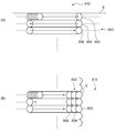
- FIG. 7 (A) and 7 (B) are schematic diagrams for demonstrating laser-beam irradiation control which the vehicle lamp which concerns on Embodiment 2 implements.
- FIG. 7A and 7B show a state in which the vehicular lamp 1 forms the high beam light distribution pattern Hi.
- illustration of the scanning area SA and the scanning locus of the laser light is omitted.
- IR high-intensity infrared laser beam
- the light source control unit 410 sets the intensity of the infrared laser light IR to a predetermined low intensity, and the scanning unit 300 has this low intensity.
- the entire area of the scan area SA is scanned with the infrared laser light IR.
- this scan is appropriately referred to as a first scan.
- the first scan is repeatedly performed at predetermined intervals.
- the pedestrian 604 is detected by the image processing apparatus 504 from the image obtained in the first scan (information from several frames before may be used)
- light source control is performed as shown in FIG. 7B.
- the unit 410 sets the intensity of the infrared laser light IR when scanning the existing area of the pedestrian 604 to a predetermined high intensity higher than the intensity in the first scan. Thereby, the strong IR irradiation area 612 is formed in the existing area of the pedestrian 604.
- the fourth laser light source 108 is turned off in the area other than the area where the pedestrian 604 is present.
- this scan is appropriately referred to as a second scan.
- the light source control unit 410 scans the entire area of the scan area SA with relatively weak infrared laser light IR, and implements a first scan for detecting an obstacle with relatively low accuracy. Then, when an obstacle is detected by the first scan, the scanning range of the infrared laser light IR is limited to the existing area of the obstacle, and the stronger infrared laser light IR is irradiated to make the obstacle more accurate. Perform a second scan to detect. As a result, highly accurate obstacle detection, reduction of power consumption, and extension of the life of the fourth laser light source 108 can be achieved.
- the “predetermined low strength” and the “predetermined high strength” can be appropriately set based on experiments and simulations by a designer.
- the control unit 400 notifies the driver of the presence of the obstacle by displaying the position information of the obstacle obtained by the second scan on a display (not shown) or the like provided on the vehicle. You may In the second scan, a region other than the region where the obstacle is present may be scanned with a predetermined low-intensity infrared laser beam IR. That is, while scanning the entire scanning area SA with the low-intensity infrared laser light IR, the intensity of the infrared laser light IR may be increased only when scanning the obstacle existing area.
- the vehicular lamp 1 according to the third embodiment is the same as the configuration of the vehicular lamp 1 according to the first embodiment except for the contents of irradiation control of laser light by the light source control unit 410.
- the same components as in the first embodiment are given the same reference numerals, and the description and illustration thereof will be appropriately omitted.
- FIG. 8A and FIG. 8B are schematic views for explaining laser light irradiation control performed by the vehicle lamp according to the third embodiment.
- FIGS. 8A and 8B the vicinity of the peripheral portion of the visible light distribution pattern is enlarged and schematically shown.
- the irradiation area 800 and the non-irradiation area 810 are overlapped in the vertical direction.
- the irradiation area 800 and the non-irradiation area 810 are parallel in the left-right direction.
- the light source control unit 410 irradiates the central portion of the visible light distribution pattern with the intensity of the white laser light W when irradiating the peripheral portion of the visible light distribution pattern. In this case, the intensity of the white laser beam W is reduced. As a result, it is possible to moderate the change in illuminance at the light-dark boundary S of the visible light distribution pattern, so it is possible to reduce the visual discomfort which is given to the driver or the pedestrian.
- the peripheral-area irradiation area 802 in contact with the light-dark boundary S in the vicinity of the light-dark boundary S, the middle-area irradiation area 804 in contact with the peripheral area irradiation area 802;
- the intensity of the white laser light W at the time of scanning each of the central irradiation regions 806 in contact with the intermediate irradiation region 804 is set to be weaker as it approaches the bright / dark boundary S.
- the illuminance of the middle irradiation region 804 is 50% of that of the central irradiation region 806, and the illuminance of the peripheral irradiation region 802 is 10% of that of the central irradiation region 806.
- the light source control unit 410 may adjust the chromaticity of the white laser light W when scanning the peripheral portion irradiation region 802. For example, due to the chromatic aberration of the fifth lens 120, a color such as blue may occur in the vicinity of the light / dark boundary S of the visible light distribution pattern. Therefore, when scanning the peripheral portion irradiation area 802, the light source control unit 410 weakens the output of the third laser light source 106 to reduce the intensity of the blue laser light B. That is, the ratio of the blue laser light B in the white laser light W is changed. Thereby, the color of the visible light distribution pattern in the vicinity of the light-dark boundary S can be made equal to that of the central portion. As a result, the visibility of the driver can be improved, and the sense of discomfort given to the driver and the pedestrian can be reduced.
- the vehicular lamp 1 according to the fourth embodiment has the same configuration as the vehicular lamp 1 according to the first embodiment except for the scanning method of the laser light.
- the same components as in the first embodiment are given the same reference numerals, and the description and illustration thereof will be appropriately omitted.
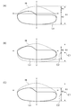
- FIGS. 9A to 9C are schematic views for explaining laser light irradiation control performed by the vehicle lamp according to the fourth embodiment.
- FIG. 9A shows the difference in scanning range of the white laser light W between the low beam light distribution pattern Lo and the high beam light distribution pattern Hi.
- FIG. 9B shows the positional relationship between the high beam light distribution pattern Hi and the low beam light distribution pattern Lo when the low beam light distribution pattern Lo is formed by changing only the amplitude in the vertical direction of the reflecting mirror 318.
- FIG. 9C shows the high beam distribution pattern Hi and the low beam distribution pattern when the low beam distribution pattern Lo is formed by changing the vertical amplitude of the reflection mirror 318 and the inclination angle of the reflection mirror 318. The positional relationship of Lo is shown.
- the amplitude of the reflecting mirror by the scanning unit can scan the irradiation area of at least the largest visible light distribution pattern with white laser light W Is set as For example, as shown in FIG. 9A, the width R1 in the vertical direction of the light distribution pattern for high beam Hi is larger than the width R2 in the vertical direction of the light distribution pattern for low beam Lo, and for the light distribution pattern Hi for high beam There is a region of a width R3 in which the low beam light distribution patterns Lo do not overlap.
- the amplitude in the vertical direction of the reflecting mirror 318 is set so that the white laser light W can scan at least the range of the width R1.
- the actuator control unit 408 rotates the reflecting mirror 318 up and down in the range of the width R1.
- the light source control unit 410 turns on the first laser light source 102 to the third laser light source 106 to emit the white laser light W when the reflecting mirror 318 is at an angle to reflect the white laser light W within the range of width R2.
- Each laser light source is turned off when the angle is such that the white laser light W is reflected within the range of the width R3. Therefore, at the time of formation of the low beam light distribution pattern Lo, the reflecting mirror 318 is unnecessarily rotated in the region of the width R3.
- the low beam light distribution pattern Lo when forming the low beam light distribution pattern Lo, it is conceivable to narrow the amplitude in the vertical direction of the reflecting mirror 318 to the width R2. As a result, it is possible to narrow the scanning interval of the white laser light W on the irradiation area of the low beam light distribution pattern Lo. Therefore, the illuminance of the low beam light distribution pattern Lo can be increased. Alternatively, the output of the laser light source when forming the low beam light distribution pattern Lo can be reduced, and power consumption can be reduced and the life of the laser light source can be prolonged.
- the vertical amplitude center C2 of the reflecting mirror 318 in forming the low beam light distribution pattern Lo simply by narrowing the vertical amplitude of the reflecting mirror 318, the vertical amplitude center C2 of the reflecting mirror 318 in forming the low beam light distribution pattern Lo;
- the amplitude center C1 in the vertical direction of the reflecting mirror 318 at the time of forming the light distribution pattern Hi for high beam remains the same. Therefore, the amplitude center C2 is shifted upward with respect to the vertical center of the low beam light distribution pattern Lo, which should be originally formed. Therefore, if the low beam light distribution pattern Lo is formed in a state where the amplitude in the vertical direction of the reflecting mirror 318 is merely narrowed, the low beam light distribution pattern Lo deviates upward from the position where it should be formed.
- the actuator control unit 408 makes the amplitude in the vertical direction of the reflecting mirror 318 narrower than when forming the light distribution pattern Hi for high beam according to the width R 2 and drives the supporting actuator 10 b to move the reflecting mirror 318 in the vertical direction.
- the inclination center (pitch angle) is adjusted, and the amplitude center C2 is displaced below the amplitude center C1.
- the actuator control unit 408 can use the signal received from the light switch 508 to grasp the formation of the low beam light distribution pattern Lo.
- the high beam distribution pattern Hi is an example of a light distribution pattern having a relatively large vertical width
- the low beam distribution pattern Lo is an example of a light distribution pattern having a relatively small vertical width.
- the light distribution pattern having a relatively large vertical width and the light distribution pattern having a relatively small vertical width are not limited to the high beam distribution pattern Hi and the low beam distribution pattern Lo.
- the present invention is not limited to the above-described embodiments, and various modifications such as design changes may be added based on the knowledge of those skilled in the art or based on the knowledge of those skilled in the art. Also included within the scope of the present invention are embodiments that are modified or modified. New embodiments resulting from the combination of each of the above-described embodiments and the above-described embodiments with the following modifications have the respective effects of the combined embodiments and modifications.
- the entire area of the scan area SA is scanned with the infrared laser light IR, but the infrared laser light IR may be irradiated only to the non-irradiated area of the visible light distribution pattern.
- the infrared laser light IR may be irradiated only to the non-irradiated area of the visible light distribution pattern.
- the driver can easily view the obstacle. Therefore, by irradiating the infrared laser light IR only to the non-irradiated area of the visible light distribution pattern, the visibility of the driver can be improved, the power consumption can be reduced, and the life of the fourth laser light source 108 can be extended. be able to.
- the vehicular lamp 1 may be equipped with an ultraviolet light source instead of or in addition to an infrared light source as a non-visible light source to form a visible light distribution pattern and scan the ultraviolet light UV as non-visible light .
- the vehicle lamp 1 may use the vehicle for detecting the position information of the detected obstacle instead of or in addition to forming the non-irradiation area 602 or the strong irradiation area 608. The driver may be notified of the presence of the obstacle by displaying it on a mounted display or the like.
- SYMBOLS 1 Vehicle lamp 100 light source unit, 102 1st laser light source, 104 2nd laser light source, 106 3rd laser light source, 108 4th laser light source, 200 condensing part, 300 scanning part, 400 control unit, 410 light source control part , 502 in-vehicle camera, 504 image processing device.
- the present invention can be used for a vehicle lamp.
Abstract
A vehicle lamp fitting (1) according to one aspect of the present invention includes: a laser light source; a scanning section (300) that scans laser light emitted from the laser light source so as to form a predetermined visible light distribution pattern; an obstacle detection section that detects an obstacle ahead the vehicle; and a control section that adjusts, on the basis of the result of detection by the obstacle detection section, an intensity of laser light when the laser light irradiates an area where the obstacle is present.
Description
本発明は、車両用灯具に関し、特に自動車などの車両に用いられる車両用灯具に関するものである。
The present invention relates to a vehicle lamp, and in particular to a vehicle lamp used for a vehicle such as a car.
特許文献1には、レーザ光を出射する半導体レーザと、蛍光体を含みレーザ光を受けて発光する発光部とを備えた車両用前照灯が開示される。この車両用前照灯では、半導体レーザから405nmの波長のレーザ光(青紫色)が出射される。また、発光体は青色、緑色及び赤色の蛍光体を含むシリコーン樹脂であり、青紫色のレーザ光を受けて白色光を生成する。発光体で生成された白色光は、反射鏡により灯具前方に反射される。
Patent Document 1 discloses a vehicular headlamp provided with a semiconductor laser for emitting a laser beam and a light emitting unit that includes a phosphor and emits a laser beam upon receiving the laser beam. In this vehicle headlamp, laser light (blue-violet) having a wavelength of 405 nm is emitted from the semiconductor laser. The light emitter is a silicone resin containing blue, green and red phosphors, and receives blue-violet laser light to generate white light. The white light generated by the light emitter is reflected forward of the lamp by the reflector.
車両用灯具は車両前方に光を照射して運転者の視認性を向上させる機能を有するが、自車前方に存在する歩行者や落下物、建造物等に対する自車運転者の視認性向上や、他車運転者に与えるグレアの低減といった性能の向上が、車両用灯具には常に要求される。このような要求は、レーザ光源を用いた車両用灯具についても例外ではない。
Vehicle lamps have a function to improve the driver's visibility by irradiating the front of the vehicle with light, but improve the driver's visibility to pedestrians, falling objects, buildings, etc. Improvements in performance, such as the reduction of glare given to drivers of other vehicles, are always required of vehicle lamps. Such requirements are no exception for vehicle lamps using laser light sources.
本発明はこうした課題に鑑みてなされたものであり、その目的は、車両用灯具の性能向上を図るための技術を提供することにある。
The present invention has been made in view of these problems, and an object thereof is to provide a technique for improving the performance of a vehicular lamp.
上記課題を解決するために、本発明のある態様は車両用灯具である。当該車両用灯具は、レーザ光源と、前記レーザ光源から出射されるレーザ光を走査して、所定の可視光配光パターンを形成する走査部と、自車前方における障害物を検知する障害物検知部と、前記障害物検知部の検知結果に基づいて、前記障害物の存在領域を照射する際の前記レーザ光の強度を調節する制御部と、を備えることを特徴とする。
In order to solve the above-mentioned subject, one mode of the present invention is a lamp for vehicles. The vehicular lamp scans a laser light source, a laser beam emitted from the laser light source, and a scanning unit that forms a predetermined visible light distribution pattern, and an obstacle detection that detects an obstacle in front of the vehicle. A control unit configured to adjust the intensity of the laser beam when irradiating the obstacle existing region based on the detection result of the obstacle detection unit.
この態様によれば、自車前方に存在する歩行者や異物に対する自車運転者の視認性を向上させることができ、また他者運転者に与えるグレアを低減することができるため、車両用灯具の性能を向上させることができる。
According to this aspect, it is possible to improve the visibility of the driver of the vehicle for pedestrians and foreign objects present in front of the vehicle, and to reduce glare given to the driver of the other vehicle. Performance can be improved.
上記態様において、前記障害物検知部は、赤外線光源と、赤外線検知部とを有し、前記走査部は、前記レーザ光とともに前記赤外線光源から出射される赤外線を走査してもよい。この態様によれば、障害物検知部を設けることによる車両用灯具の製造コストや部品点数の増大、大型化を抑制することができる。
In the above aspect, the obstacle detection unit may include an infrared light source and an infrared detection unit, and the scanning unit may scan the infrared light emitted from the infrared light source together with the laser light. According to this aspect, it is possible to suppress the increase in the manufacturing cost and the number of parts of the vehicle lamp and the increase in the size due to the provision of the obstacle detection unit.
また、上記いずれかの態様において、前記制御部は、前記可視光配光パターンの周縁部を照射する際の前記レーザ光の強度を、前記可視光配光パターンの中心部を照射する際の前記レーザ光の強度よりも低減させてもよい。この態様によれば、可視光配光パターンの明暗境界における照度変化を緩やかにすることができるため、運転者や歩行者に与える視覚的な違和感を低減させることができる。
Further, in any one of the above aspects, the control unit is configured to irradiate the central portion of the visible light distribution pattern with the intensity of the laser light when the peripheral portion of the visible light distribution pattern is irradiated. It may be lower than the intensity of the laser beam. According to this aspect, it is possible to moderate the change in illuminance at the light and dark boundary of the visible light distribution pattern, so it is possible to reduce the visual discomfort which is given to the driver and the pedestrian.
なお、以上の構成要素の任意の組み合わせや、本発明の構成要素や表現を方法、装置、システムなどの間で相互に置換したものもまた、本発明の態様として有効である。
It is to be noted that any combination of the above-described constituent elements, or one obtained by replacing the constituent elements and expressions of the present invention among methods, apparatuses, systems, etc. is also effective as an aspect of the present invention.
本発明によれば、車両用灯具の性能向上を図るための技術を提供することができる。
According to the present invention, it is possible to provide a technique for improving the performance of a vehicular lamp.
以下、本発明を好適な実施の形態をもとに図面を参照しながら説明する。各図面に示される同一または同等の構成要素、部材、処理には、同一の符号を付するものとし、適宜重複した説明は省略する。また、実施の形態は、発明を限定するものではなく例示であって、実施の形態に記述されるすべての特徴やその組み合わせは、必ずしも発明の本質的なものであるとは限らない。
Hereinafter, the present invention will be described based on preferred embodiments with reference to the drawings. The same or equivalent components, members, and processes shown in the drawings are denoted by the same reference numerals, and duplicating descriptions will be omitted as appropriate. In addition, the embodiments do not limit the invention and are merely examples, and all the features and combinations thereof described in the embodiments are not necessarily essential to the invention.
(実施形態1)
図1は、実施形態1に係る車両用灯具の概略構造を示す鉛直断面図である。なお、図1は、光源ユニット100の内部を透視した状態を図示している。また、走査部300の永久磁石312,314の図示を省略している。本実施形態に係る車両用灯具は、例えば、車両前方の左右に配置される一対の前照灯ユニットを有する車両用前照灯装置である。一対の前照灯ユニットは、実質的に同一の構成であるため、図1には車両用灯具1として左右いずれかの前照灯ユニットの構成を示す。 (Embodiment 1)
FIG. 1 is a vertical cross-sectional view showing a schematic structure of the vehicle lamp according to the first embodiment. Note that FIG. 1 illustrates a state in which the inside of thelight source unit 100 is seen through. Further, illustration of the permanent magnets 312 and 314 of the scanning unit 300 is omitted. The vehicular lamp according to the present embodiment is, for example, a vehicular headlamp apparatus having a pair of headlamp units disposed on the left and right of the front of the vehicle. Since the pair of headlight units have substantially the same configuration, FIG. 1 shows the configuration of the left or right headlight unit as the vehicular lamp 1.
図1は、実施形態1に係る車両用灯具の概略構造を示す鉛直断面図である。なお、図1は、光源ユニット100の内部を透視した状態を図示している。また、走査部300の永久磁石312,314の図示を省略している。本実施形態に係る車両用灯具は、例えば、車両前方の左右に配置される一対の前照灯ユニットを有する車両用前照灯装置である。一対の前照灯ユニットは、実質的に同一の構成であるため、図1には車両用灯具1として左右いずれかの前照灯ユニットの構成を示す。 (Embodiment 1)
FIG. 1 is a vertical cross-sectional view showing a schematic structure of the vehicle lamp according to the first embodiment. Note that FIG. 1 illustrates a state in which the inside of the
車両用灯具1は、車両前方側に開口部を有するランプボディ2と、ランプボディ2の開口部を覆う透光カバー4とを備える。透光カバー4は、透光性を有する樹脂やガラス等で形成される。ランプボディ2と透光カバー4とにより形成される灯室3内には、支持プレート6と、光源ユニット100と、走査部300と、制御ユニット400とが収容される。
The vehicular lamp 1 includes a lamp body 2 having an opening on the front side of the vehicle, and a translucent cover 4 that covers the opening of the lamp body 2. The translucent cover 4 is formed of a translucent resin, glass, or the like. The support plate 6, the light source unit 100, the scanning unit 300, and the control unit 400 are accommodated in the lamp chamber 3 formed by the lamp body 2 and the light transmitting cover 4.
光源ユニット100及び走査部300は、支持プレート6により灯室3内の所定位置に支持される。支持プレート6は、コーナー部がエイミングスクリュー8によってランプボディ2に接続される。光源ユニット100は、第1レーザ光源102、第2レーザ光源104、第3レーザ光源106、第4レーザ光源108、ヒートシンク110及び集光部200等を有する。光源ユニット100は、ヒートシンク110が支持プレート6に接するようにして、支持プレート6の前面に固定される。光源ユニット100の内部構造については後に詳細に説明する。
The light source unit 100 and the scanning unit 300 are supported by the support plate 6 at a predetermined position in the lamp chamber 3. The support plate 6 is connected at its corners to the lamp body 2 by the aiming screw 8. The light source unit 100 includes a first laser light source 102, a second laser light source 104, a third laser light source 106, a fourth laser light source 108, a heat sink 110, a light collecting unit 200, and the like. The light source unit 100 is fixed to the front surface of the support plate 6 such that the heat sink 110 is in contact with the support plate 6. The internal structure of the light source unit 100 will be described in detail later.
走査部300は、反射鏡318を有する。走査部300の構造については後に詳細に説明する。走査部300は、光源ユニット100から出射されたレーザ光を灯具前方に反射するように光源ユニット100との位置関係が定められて、支持プレート6の前面から灯具前方側に突出する突出部10に固定される。突出部10はピボット機構10aを備え、走査部300はピボット機構10aを介して突出部10に支持される。また、突出部10は、ロッドと、このロッドを灯具前後方向に伸縮させるモータとを有する支持用アクチュエータ10bを備える。ロッドの先端は、走査部300に接続される。突出部10は、ロッドを伸縮させることで、ピボット機構10aを軸として走査部300を揺動させることができ、これにより走査部300の鉛直方向の傾斜角度(ピッチ角度)を調整することができる。支持用アクチュエータ10bは制御ユニット400に接続され、制御ユニット400の後述するアクチュエータ制御部408(図5参照)により駆動が制御される。制御ユニット400は、支持プレート6よりも灯具後方側でランプボディ2に固定される。なお、制御ユニット400を設ける位置は、特にこれに限定されない。
The scanning unit 300 has a reflecting mirror 318. The structure of the scanning unit 300 will be described in detail later. The scanning unit 300 has a positional relationship with the light source unit 100 determined so as to reflect the laser light emitted from the light source unit 100 to the front of the lamp, and the projecting portion 10 protrudes from the front surface of the support plate 6 to the lamp front side. It is fixed. The protrusion 10 includes a pivot mechanism 10 a, and the scanning unit 300 is supported by the protrusion 10 via the pivot mechanism 10 a. In addition, the protrusion 10 includes a support actuator 10 b having a rod and a motor that extends and retracts the rod in the front-rear direction of the lamp. The tip of the rod is connected to the scanning unit 300. The projecting portion 10 can swing the scanning portion 300 about the pivot mechanism 10a by expanding and contracting the rod, whereby the inclination angle (pitch angle) of the scanning portion 300 in the vertical direction can be adjusted. . The supporting actuator 10b is connected to the control unit 400, and its drive is controlled by an actuator control unit 408 (see FIG. 5) of the control unit 400 described later. The control unit 400 is fixed to the lamp body 2 on the lamp rear side with respect to the support plate 6. The position where the control unit 400 is provided is not particularly limited.
車両用灯具1は、エイミングスクリュー8を回転させて支持プレート6の姿勢を調節することで光軸を水平方向及び鉛直方向に調整可能である。灯室3内における光源ユニット100及び走査部300の灯具前方側には、走査部300によって反射された光の灯具前方への進行を許容する開口部を有するエクステンション部材12が設けられる。続いて、車両用灯具1を構成する各部の構成について詳細に説明する。
The vehicular lamp 1 can adjust the optical axis in the horizontal direction and the vertical direction by rotating the aiming screw 8 to adjust the posture of the support plate 6. On the lamp front side of the light source unit 100 and the scanning unit 300 in the lamp chamber 3, an extension member 12 having an opening that allows the light reflected by the scanning unit 300 to travel forward of the lamp is provided. Subsequently, the configuration of each part constituting the vehicular lamp 1 will be described in detail.
(光源ユニット)
図2は、光源ユニットの概略構造を示す側面図である。なお、図2では、光源ユニット100の内部を透視した状態を図示している。光源ユニット100は、第1レーザ光源102、第2レーザ光源104、第3レーザ光源106、第4レーザ光源108、ヒートシンク110、第1レンズ112、第2レンズ114、第3レンズ116、第4レンズ118、第5レンズ120及び集光部200等を有する。 (Light source unit)
FIG. 2 is a side view showing a schematic structure of the light source unit. Note that FIG. 2 illustrates a state in which the inside of thelight source unit 100 is seen through. The light source unit 100 includes a first laser light source 102, a second laser light source 104, a third laser light source 106, a fourth laser light source 108, a heat sink 110, a first lens 112, a second lens 114, a third lens 116, and a fourth lens. It has 118, the 5th lens 120, and condensing part 200 grade.
図2は、光源ユニットの概略構造を示す側面図である。なお、図2では、光源ユニット100の内部を透視した状態を図示している。光源ユニット100は、第1レーザ光源102、第2レーザ光源104、第3レーザ光源106、第4レーザ光源108、ヒートシンク110、第1レンズ112、第2レンズ114、第3レンズ116、第4レンズ118、第5レンズ120及び集光部200等を有する。 (Light source unit)
FIG. 2 is a side view showing a schematic structure of the light source unit. Note that FIG. 2 illustrates a state in which the inside of the
第1レーザ光源102は、赤色レーザダイオードで構成され、赤色レーザ光Rを出射する。第2レーザ光源104は、緑色レーザダイオードで構成され、緑色レーザ光Gを出射する。第3レーザ光源106は、青色レーザダイオードで構成され、青色レーザ光Bを出射する。第4レーザ光源108(赤外線光源)は、赤外レーザダイオードで構成され、赤外レーザ光IR(赤外線)を出射する。第1レーザ光源102~第4レーザ光源108は、共通の基板109に搭載されている。なお、各光源は、レーザダイオード以外のレーザ装置を有してもよい。また、赤外線光源は、レーザ光源以外の光源であってもよい。
The first laser light source 102 is configured by a red laser diode and emits red laser light R. The second laser light source 104 is constituted by a green laser diode and emits green laser light G. The third laser light source 106 is composed of a blue laser diode and emits blue laser light B. The fourth laser light source 108 (infrared light source) is composed of an infrared laser diode and emits infrared laser light IR (infrared light). The first to fourth laser light sources 102 to 108 are mounted on a common substrate 109. Each light source may have a laser device other than a laser diode. The infrared light source may be a light source other than the laser light source.
第1レーザ光源102、第2レーザ光源104、第3レーザ光源106及び第4レーザ光源108は、それぞれのレーザ光出射面が灯具前方側を向き、基板109が灯具後方側を向くように配置され、ヒートシンク110の灯具前方側の面に取り付けられる。ヒートシンク110は、各レーザ光源が発する熱を効率よく回収できるよう、アルミニウムなどの熱伝導率が高い材料によって形成される。ヒートシンク110の灯具後方側の面は、支持プレート6(図1参照)に接する。各レーザ光源は、基板109、ヒートシンク110及び支持プレート6を介して放熱される。
The first laser light source 102, the second laser light source 104, the third laser light source 106, and the fourth laser light source 108 are disposed such that their respective laser light emitting surfaces face the lamp front side and the substrate 109 faces the lamp back side. , Mounted on the surface of the heat sink 110 on the front side of the lamp. The heat sink 110 is formed of a material having high thermal conductivity such as aluminum so that the heat generated by each laser light source can be efficiently recovered. The surface on the lamp rear side of the heat sink 110 is in contact with the support plate 6 (see FIG. 1). Each laser light source dissipates heat via the substrate 109, the heat sink 110 and the support plate 6.
第1レンズ112、第2レンズ114、第3レンズ116、第4レンズ118及び第5レンズ120は、例えばコリメートレンズで構成される。第1レンズ112は、第1レーザ光源102と集光部200との間の赤色レーザ光Rの光路上に設けられ、第1レーザ光源102から集光部200に向かう赤色レーザ光Rを平行光に変換する。第2レンズ114は、第2レーザ光源104と集光部200との間の緑色レーザ光Gの光路上に設けられ、第2レーザ光源104から集光部200に向かう緑色レーザ光Gを平行光に変換する。第3レンズ116は、第3レーザ光源106と集光部200との間の青色レーザ光Bの光路上に設けられ、第3レーザ光源106から集光部200に向かう青色レーザ光Bを平行光に変換する。
The first lens 112, the second lens 114, the third lens 116, the fourth lens 118, and the fifth lens 120 are configured by, for example, a collimator lens. The first lens 112 is provided on the optical path of the red laser light R between the first laser light source 102 and the light collecting unit 200, and collimates the red laser light R traveling from the first laser light source 102 toward the light collecting unit 200. Convert to The second lens 114 is provided on the optical path of the green laser light G between the second laser light source 104 and the light collecting unit 200, and collimates the green laser light G traveling from the second laser light source 104 toward the light collecting unit 200. Convert to The third lens 116 is provided on the optical path of the blue laser light B between the third laser light source 106 and the light collecting unit 200, and collimates the blue laser light B traveling from the third laser light source 106 toward the light collecting unit 200. Convert to
第4レンズ118は、第4レーザ光源108と集光部200との間の赤外レーザ光IRの光路上に設けられ、第4レーザ光源108から集光部200に向かう赤外レーザ光IRを平行光に変換する。第5レンズ120は、光源ユニット100の筐体に設けられた開口101に嵌め合わされる。第5レンズ120は、集光部200と走査部300(図1参照)との間の、後述する白色レーザ光W及び赤外レーザ光IRの光路上に設けられ、集光部200から走査部300に向かう白色レーザ光W及び赤外レーザ光IRを平行光に変換する。
The fourth lens 118 is provided on the optical path of the infrared laser light IR between the fourth laser light source 108 and the light collecting unit 200, and the infrared laser light IR traveling from the fourth laser light source 108 toward the light collecting unit 200 is Convert to collimated light. The fifth lens 120 is fitted in the opening 101 provided in the housing of the light source unit 100. The fifth lens 120 is provided on the light path of the white laser light W and the infrared laser light IR, which will be described later, between the light collecting unit 200 and the scanning unit 300 (see FIG. 1). The white laser light W and the infrared laser light IR traveling to 300 are converted into parallel light.
集光部200は、赤色レーザ光R、緑色レーザ光G及び青色レーザ光Bを集合させて白色レーザ光Wを生成する。また、白色レーザ光Wに赤外レーザ光IRを集合させる。集光部200は、第1ダイクロイックミラー202、第2ダイクロイックミラー204、第3ダイクロイックミラー206及び第4ダイクロイックミラー208を有する。
The condensing unit 200 generates the white laser light W by aggregating the red laser light R, the green laser light G, and the blue laser light B. In addition, the infrared laser light IR is gathered in the white laser light W. The condensing unit 200 includes a first dichroic mirror 202, a second dichroic mirror 204, a third dichroic mirror 206, and a fourth dichroic mirror 208.
第1ダイクロイックミラー202は、少なくとも赤色光を反射し青色光、緑色光及び赤外光を透過させるミラーであり、第1レンズ112を通過した赤色レーザ光Rを第5レンズ120に向けて反射するように配置される。第2ダイクロイックミラー204は、少なくとも緑色光を反射し青色光及び赤外光を透過させるミラーであり、第2レンズ114を通過した緑色レーザ光Gを第5レンズ120に向けて反射するように配置される。第3ダイクロイックミラー206は、少なくとも青色光を反射し赤外光を透過させるミラーであり、第3レンズ116を通過した青色レーザ光Bを第5レンズ120に向けて反射するように配置される。第4ダイクロイックミラー208は、少なくとも赤外光を反射するミラーであり、第4レンズ118を通過した赤外レーザ光IRを第5レンズ120に向けて反射するように配置される。
The first dichroic mirror 202 is a mirror that reflects at least red light and transmits blue light, green light and infrared light, and reflects the red laser light R that has passed through the first lens 112 toward the fifth lens 120 Arranged as. The second dichroic mirror 204 is a mirror that reflects at least green light and transmits blue light and infrared light, and is arranged to reflect the green laser light G that has passed through the second lens 114 toward the fifth lens 120. Be done. The third dichroic mirror 206 is a mirror that reflects at least blue light and transmits infrared light, and is disposed to reflect the blue laser light B that has passed through the third lens 116 toward the fifth lens 120. The fourth dichroic mirror 208 is a mirror that reflects at least infrared light, and is arranged to reflect the infrared laser light IR that has passed through the fourth lens 118 toward the fifth lens 120.
各ダイクロイックミラーは、それぞれが反射したレーザ光の光路が平行で、且つ各レーザ光が集合して第5レンズ120に入射されるように互いの位置関係が定められる。本実施形態では、第1ダイクロイックミラー202~第4ダイクロイックミラー208は、各ダイクロイックミラーにおいてレーザ光が当たる領域(レーザ光の反射点)が一直線上に並ぶように配置されている。
The respective dichroic mirrors have their positional relationship determined so that the optical paths of the laser beams reflected by the respective dichroic mirrors are parallel, and the respective laser beams are collectively incident on the fifth lens 120. In the present embodiment, the first dichroic mirror 202 to the fourth dichroic mirror 208 are arranged such that the regions (reflection points of the laser light) on which the laser light impinges in each dichroic mirror are aligned in a straight line.
第4レーザ光源108から出射された赤外レーザ光IRは、第4ダイクロイックミラー208で反射され、第3ダイクロイックミラー206側に進行する。第3レーザ光源106から出射された青色レーザ光Bは、第3ダイクロイックミラー206により第2ダイクロイックミラー204側に反射されるとともに、第3ダイクロイックミラー206を透過した赤外レーザ光IRと重ね合わされる。第2レーザ光源104から出射された緑色レーザ光Gは、第2ダイクロイックミラー204により第1ダイクロイックミラー202側に反射されるとともに、第2ダイクロイックミラー204を透過した赤外レーザ光IR及び青色レーザ光Bの集合光と重ね合わせられる。第1レーザ光源102から出射された赤色レーザ光Rは、第1ダイクロイックミラー202により第5レンズ120側に反射されるとともに、第1ダイクロイックミラー202を透過した赤外レーザ光IR、青色レーザ光B及び緑色レーザ光Gの集合光と重ね合わせられる。その結果、赤外レーザ光IRを含む白色レーザ光Wが形成される。赤外レーザ光IRと白色レーザ光Wとの混合レーザ光は、第5レンズ120を通過して走査部300に向けて進行する。
The infrared laser light IR emitted from the fourth laser light source 108 is reflected by the fourth dichroic mirror 208 and travels to the third dichroic mirror 206 side. The blue laser light B emitted from the third laser light source 106 is reflected by the third dichroic mirror 206 toward the second dichroic mirror 204, and is superimposed on the infrared laser light IR transmitted through the third dichroic mirror 206. . The green laser light G emitted from the second laser light source 104 is reflected by the second dichroic mirror 204 toward the first dichroic mirror 202, and the infrared laser light IR and the blue laser light transmitted through the second dichroic mirror 204 It is superimposed on the collective light of B. The red laser light R emitted from the first laser light source 102 is reflected toward the fifth lens 120 by the first dichroic mirror 202, and the infrared laser light IR and the blue laser light B transmitted through the first dichroic mirror 202. And the collective light of the green laser light G. As a result, white laser light W including infrared laser light IR is formed. The mixed laser beam of the infrared laser beam IR and the white laser beam W passes through the fifth lens 120 and travels toward the scanning unit 300.
光源ユニット100は、各レーザ光の出射を監視する監視部130を有する。監視部130は、第1フォトセンサ132、第2フォトセンサ134、第3フォトセンサ136、第4フォトセンサ138、第5フォトセンサ139及び異常判定部140を有する。第1フォトセンサ132は、赤色レーザ光Rの強度を測定する。第2フォトセンサ134は、緑色レーザ光Gの強度を測定する。第3フォトセンサ136は、青色レーザ光Bの強度を測定する。第4フォトセンサ138は、赤外レーザ光IRの強度を測定する。第5フォトセンサ139は、白色レーザ光Wと赤外レーザ光IRの集合光の強度を測定する。各フォトセンサは、測定値を示す信号を異常判定部140に送信する。
The light source unit 100 has a monitoring unit 130 that monitors emission of each laser beam. The monitoring unit 130 includes a first photosensor 132, a second photosensor 134, a third photosensor 136, a fourth photosensor 138, a fifth photosensor 139, and an abnormality determination unit 140. The first photosensor 132 measures the intensity of the red laser light R. The second photosensor 134 measures the intensity of the green laser light G. The third photosensor 136 measures the intensity of the blue laser light B. The fourth photosensor 138 measures the intensity of the infrared laser light IR. The fifth photosensor 139 measures the intensity of the combined light of the white laser light W and the infrared laser light IR. Each photosensor transmits a signal indicating the measured value to the abnormality determination unit 140.
異常判定部140は、第1フォトセンサ132~第4フォトセンサ138の測定値と予め定められた照射強度の設定範囲とを比較して、各レーザ光源にレーザ光の出射異常が生じているか否かを判定する。また、異常判定部140は、第5フォトセンサ139の測定値を用いて、白色レーザ光Wの強度、若しくは白色レーザ光Wと赤外レーザ光IRの集合光の強度が所定の設定範囲に含まれるか否かを判定する。異常判定部140は、第5フォトセンサ139での測定値から第4フォトセンサ138での測定値を減算することで白色レーザ光Wの強度を算出することができる。異常判定部140は、判定結果を示す信号を制御ユニット400に送信する。なお、異常判定部140は、制御ユニット400内に設けられてもよい。
The abnormality determination unit 140 compares the measurement values of the first photo sensor 132 to the fourth photo sensor 138 with the preset setting range of the irradiation intensity, and determines whether or not the laser light emission abnormality occurs in each laser light source. Determine if In addition, the abnormality determination unit 140 uses the measured value of the fifth photosensor 139 to include the intensity of the white laser light W or the intensity of the combined light of the white laser light W and the infrared laser light IR in a predetermined setting range. It is determined whether the The abnormality determination unit 140 can calculate the intensity of the white laser light W by subtracting the measurement value of the fourth photosensor 138 from the measurement value of the fifth photosensor 139. The abnormality determination unit 140 transmits a signal indicating the determination result to the control unit 400. The abnormality determination unit 140 may be provided in the control unit 400.
(走査部)
図3は、灯具前方側から観察したときの走査部の概略斜視図である。走査部300は、第1レーザ光源102~第3レーザ光源106から出射されるレーザ光を走査して、所定の可視光配光パターン(図4参照)を形成するための機構である。また、走査部300は、赤外レーザ光IRで車両前方を走査する。走査部300は、例えば、いわゆるガルバノミラーで構成され、ベース302、第1回動体304、第2回動体306、第1トーションバー308、第2トーションバー310、永久磁石312,314、端子部316及び反射鏡318等を有する。ベース302は、中央に開口部302aを有する枠体であり、灯具前後方向に傾斜した状態で突出部10(図1参照)の先端に固定される。ベース302には、所定位置に端子部316が設けられる。開口部302aには、第1回動体304が配置される。第1回動体304は、中央に開口部304aを有する枠体であり、灯具後方下側から灯具前方上側に延在する第1トーションバー308により、ベース302に対し左右(車幅方向)に回動可能に支持される。 (Scanning unit)
FIG. 3 is a schematic perspective view of the scanning unit when observed from the front side of the lamp. Thescanning unit 300 is a mechanism for scanning laser light emitted from the first laser light source 102 to the third laser light source 106 to form a predetermined visible light distribution pattern (see FIG. 4). The scanning unit 300 scans the front of the vehicle with the infrared laser light IR. The scanning unit 300 is formed of, for example, a so-called galvano mirror, and the base 302, the first rotating body 304, the second rotating body 306, the first torsion bar 308, the second torsion bar 310, the permanent magnets 312 and 314, and the terminal portion 316. And a reflecting mirror 318 and the like. The base 302 is a frame having an opening 302a at the center, and is fixed to the tip of the projection 10 (see FIG. 1) in a state of being inclined in the front-rear direction of the lamp. A terminal portion 316 is provided on the base 302 at a predetermined position. The first pivoting body 304 is disposed in the opening 302a. The first pivoting body 304 is a frame having an opening 304a at the center, and is pivoted to the left and right (in the vehicle width direction) with respect to the base 302 by the first torsion bar 308 extending from the lamp rear lower side to the lamp front upper side. It is movably supported.
図3は、灯具前方側から観察したときの走査部の概略斜視図である。走査部300は、第1レーザ光源102~第3レーザ光源106から出射されるレーザ光を走査して、所定の可視光配光パターン(図4参照)を形成するための機構である。また、走査部300は、赤外レーザ光IRで車両前方を走査する。走査部300は、例えば、いわゆるガルバノミラーで構成され、ベース302、第1回動体304、第2回動体306、第1トーションバー308、第2トーションバー310、永久磁石312,314、端子部316及び反射鏡318等を有する。ベース302は、中央に開口部302aを有する枠体であり、灯具前後方向に傾斜した状態で突出部10(図1参照)の先端に固定される。ベース302には、所定位置に端子部316が設けられる。開口部302aには、第1回動体304が配置される。第1回動体304は、中央に開口部304aを有する枠体であり、灯具後方下側から灯具前方上側に延在する第1トーションバー308により、ベース302に対し左右(車幅方向)に回動可能に支持される。 (Scanning unit)
FIG. 3 is a schematic perspective view of the scanning unit when observed from the front side of the lamp. The
第1回動体304の開口部304aには、第2回動体306が配置される。第2回動体306は、矩形状の平板であり、車幅方向に延在する第2トーションバー310により、第1回動体304に対し上下(鉛直方向)に回動可能に支持される。第2回動体306は、第1回動体304が第1トーションバー308を回動軸として左右に回動すると、第1回動体304とともに左右に回動する。第2回動体306の表面には、メッキ又は蒸着等の方法により反射鏡318が設けられる。
The second pivoting body 306 is disposed in the opening 304 a of the first pivoting body 304. The second pivoting body 306 is a rectangular flat plate, and is rotatably supported vertically (vertically) with respect to the first pivoting body 304 by a second torsion bar 310 extending in the vehicle width direction. The second pivoting body 306 pivots left and right together with the first pivoting body 304 when the first pivoting body 304 pivots left and right with the first torsion bar 308 as a pivoting axis. A reflecting mirror 318 is provided on the surface of the second rotating body 306 by a method such as plating or vapor deposition.
ベース302には、第1トーションバー308の延在方向と直交する位置に、一対の永久磁石312が設けられる。永久磁石312は、第1トーションバー308と直交する磁界を形成する。第1回動体304には第1コイル(図示せず)が配線され、第1コイルは端子部316を介して制御ユニット400に接続される。また、ベース302には、第2トーションバー310の延在方向と直交する位置に、一対の永久磁石314が設けられる。永久磁石314は、第2トーションバー310と直交する磁界を形成する。第2回動体306には第2コイル(図示せず)が配線され、第2コイルは端子部316を介して制御ユニット400に接続される。
The base 302 is provided with a pair of permanent magnets 312 at a position orthogonal to the extending direction of the first torsion bar 308. The permanent magnet 312 forms a magnetic field orthogonal to the first torsion bar 308. A first coil (not shown) is wired to the first rotating body 304, and the first coil is connected to the control unit 400 via the terminal portion 316. Further, the base 302 is provided with a pair of permanent magnets 314 at a position orthogonal to the extending direction of the second torsion bar 310. The permanent magnet 314 forms a magnetic field orthogonal to the second torsion bar 310. A second coil (not shown) is wired to the second rotating body 306, and the second coil is connected to the control unit 400 via the terminal portion 316.
第1コイル及び永久磁石312と、第2コイル及び永久磁石314とにより走査用アクチュエータ320(図5参照)が構成される。走査用アクチュエータ320は、後述するアクチュエータ制御部408(図5参照)により駆動が制御される。アクチュエータ制御部408は、第1コイル及び第2コイルに流れる駆動電圧の大きさと向きを制御する。これにより、第1回動体304及び第2回動体306が左右に往復回動し、また第2回動体306が単独で上下に往復回動する。その結果、反射鏡318が上下左右に往復回動する。また、駆動電圧の大きさの制御により、第2回動体306の往復回動の幅(振幅)が調整される。
The first coil and permanent magnet 312 and the second coil and permanent magnet 314 constitute a scanning actuator 320 (see FIG. 5). The drive of the scanning actuator 320 is controlled by an actuator control unit 408 (see FIG. 5) described later. The actuator control unit 408 controls the magnitude and direction of the drive voltage flowing to the first coil and the second coil. As a result, the first rotating body 304 and the second rotating body 306 reciprocate in the left and right directions, and the second rotating body 306 independently reciprocates in the vertical direction. As a result, the reflecting mirror 318 reciprocates in the vertical and horizontal directions. Further, by controlling the magnitude of the drive voltage, the width (amplitude) of the reciprocating rotation of the second rotating body 306 is adjusted.
光源ユニット100と走査部300とは、光源ユニット100から出射された白色レーザ光W及び赤外レーザ光IRが反射鏡318で灯具前方に反射されるよう互いの位置関係が定められる。そして、走査部300は、反射鏡318の往復回動により白色レーザ光W及び赤外レーザ光IRで車両前方を走査する。例えば走査部300は、配光パターンの形成領域よりも広い走査範囲で反射鏡318を回動させる。そして、制御ユニット400の後述する光源制御部410(図5参照)は、反射鏡318の回動位置が可視光配光パターンの形成領域に対応する位置にあるとき第1レーザ光源102~第3レーザ光源106を点灯させる。これにより、白色レーザ光Wが可視光配光パターンの形成領域に配光されて、車両前方に所定の可視光配光パターンが形成される。この場合、光源制御部410は、走査部300の一部を構成する。また、例えば光源制御部410は、常に第4レーザ光源108を点灯させる。これにより、反射鏡318の回動範囲(走査領域)の全域が赤外レーザ光IRで走査される。赤外レーザ光IRは、後述する障害物検知に利用される。
The positional relationship between the light source unit 100 and the scanning unit 300 is determined such that the white laser light W and the infrared laser light IR emitted from the light source unit 100 are reflected by the reflecting mirror 318 in front of the lamp. Then, the scanning unit 300 scans the front of the vehicle with the white laser light W and the infrared laser light IR by the reciprocal rotation of the reflecting mirror 318. For example, the scanning unit 300 rotates the reflecting mirror 318 in a scanning range wider than the formation area of the light distribution pattern. The light source control unit 410 (see FIG. 5) of the control unit 400 described later (see FIG. 5) is configured such that the first laser light source 102 to the third light source 102 are located when the rotational position of the reflecting mirror 318 is at a position corresponding to the formation region The laser light source 106 is turned on. Thereby, the white laser light W is distributed to the formation region of the visible light distribution pattern, and a predetermined visible light distribution pattern is formed in front of the vehicle. In this case, the light source control unit 410 constitutes a part of the scanning unit 300. Also, for example, the light source control unit 410 always turns on the fourth laser light source 108. Thereby, the whole range of the rotation range (scanning region) of the reflecting mirror 318 is scanned by the infrared laser light IR. The infrared laser light IR is used for obstacle detection described later.
図4は、実施形態1に係る車両用灯具により形成される可視光配光パターンの一例を示す図である。なお、図4では、灯具前方の所定位置、例えば灯具前方25mの位置に配置された仮想鉛直スクリーン上に形成された可視光配光パターンを示している。また、レーザ光の走査の軌跡は、模式的に示している。走査部300は、車幅方向に延在する矩形の走査領域SA内をレーザ光でスキャン可能である。光源制御部410は、走査部300によるレーザ光の走査位置がロービーム用配光パターンLo内である場合に、第1レーザ光源102~第4レーザ光源108からレーザ光を出射させ、当該走査位置がロービーム用配光パターンLo外である場合に、第1レーザ光源102~第3レーザ光源106からのレーザ光の出射を停止させる。これにより、対向車線側カットオフラインCL1、自車線側カットオフラインCL2及び斜めカットオフラインCL3を有するロービーム用配光パターンLoが形成される。なお、車両用灯具1は、ハイビーム用配光パターン等の他の配光パターンも形成することができる。
FIG. 4 is a view showing an example of a visible light distribution pattern formed by the vehicle lamp according to the first embodiment. FIG. 4 shows a visible light distribution pattern formed on a virtual vertical screen disposed at a predetermined position in front of the lamp, for example, 25 m in front of the lamp. Further, a locus of scanning of the laser light is schematically shown. The scanning unit 300 can scan the inside of a rectangular scanning area SA extending in the vehicle width direction with laser light. The light source control unit 410 causes the first laser light source 102 to the fourth laser light source 108 to emit laser light when the scanning position of the laser light by the scanning unit 300 is in the low beam light distribution pattern Lo, and the scanning position is When it is outside the low beam light distribution pattern Lo, the emission of laser light from the first laser light source 102 to the third laser light source 106 is stopped. As a result, a low beam light distribution pattern Lo having the oncoming traffic lane side cutoff line CL1, the own traffic lane side cutoff line CL2, and the oblique cutoff line CL3 is formed. Note that the vehicle lamp 1 can also form other light distribution patterns such as a high beam light distribution pattern.
(制御ユニット)
図5は、制御ユニットを説明する機能ブロック図である。なお、図5に示す機能ブロックがハードウェア、ソフトウェアの組合せによっていろいろなかたちで実現できることは、当業者には理解されるところである。制御ユニット400は、灯具ECU402、ROM404、RAM406等を有する。灯具ECU402は、アクチュエータ制御部408及び光源制御部410(制御部)を有する。ROM404は、各種制御プログラムを格納する。RAM406は、データ格納や灯具ECU402によるプログラム実行のためのワークエリアとして利用される。灯具ECU402は、ROM404に格納された複数の制御プログラムを適宜選択的に実行し、各種制御信号を生成する。 (Controller unit)
FIG. 5 is a functional block diagram for explaining the control unit. It should be understood by those skilled in the art that the functional blocks shown in FIG. 5 can be realized in various forms by a combination of hardware and software. Thecontrol unit 400 includes a lamp ECU 402, a ROM 404, a RAM 406, and the like. The lamp ECU 402 includes an actuator control unit 408 and a light source control unit 410 (control unit). The ROM 404 stores various control programs. The RAM 406 is used as a work area for data storage and program execution by the lamp ECU 402. The lamp ECU 402 appropriately executes a plurality of control programs stored in the ROM 404 appropriately to generate various control signals.
図5は、制御ユニットを説明する機能ブロック図である。なお、図5に示す機能ブロックがハードウェア、ソフトウェアの組合せによっていろいろなかたちで実現できることは、当業者には理解されるところである。制御ユニット400は、灯具ECU402、ROM404、RAM406等を有する。灯具ECU402は、アクチュエータ制御部408及び光源制御部410(制御部)を有する。ROM404は、各種制御プログラムを格納する。RAM406は、データ格納や灯具ECU402によるプログラム実行のためのワークエリアとして利用される。灯具ECU402は、ROM404に格納された複数の制御プログラムを適宜選択的に実行し、各種制御信号を生成する。 (Controller unit)
FIG. 5 is a functional block diagram for explaining the control unit. It should be understood by those skilled in the art that the functional blocks shown in FIG. 5 can be realized in various forms by a combination of hardware and software. The
アクチュエータ制御部408は、走査部300の走査用アクチュエータ320と、突出部10の支持用アクチュエータ10bを制御する。光源制御部410は、第1レーザ光源102~第4レーザ光源108のレーザ光の出射を各光源独立に制御する。例えば、灯具ECU402は、車両に設けられたライトスイッチ508からの信号を受信可能である。灯具ECU402がライトスイッチ508から車両用灯具1の点消灯を指示する信号を受信すると、光源制御部410は各レーザ光源の点消灯を制御する。光源制御部410による制御は後に詳細に説明する。
The actuator control unit 408 controls the scanning actuator 320 of the scanning unit 300 and the support actuator 10 b of the protrusion 10. The light source control unit 410 controls emission of laser light of the first laser light source 102 to the fourth laser light source 108 independently for each light source. For example, the lamp ECU 402 can receive a signal from the light switch 508 provided in the vehicle. When the lamp ECU 402 receives a signal instructing on / off of the vehicle lamp 1 from the light switch 508, the light source control unit 410 controls the on / off of each laser light source. Control by the light source control unit 410 will be described in detail later.
また、灯具ECU402は、監視部130の異常判定部140からの信号を受信可能である。光源制御部410は、監視部130から得られた信号を用いて、各レーザ光源の出力を調整する制御信号を生成する。また、灯具ECU402は、光源の出力異常を報知する報知部500に動作指令信号を送信可能である。報知部500は、例えば車両内に設けられる警告灯(インジケータランプ)等で構成することができる。
Further, the lamp ECU 402 can receive a signal from the abnormality determination unit 140 of the monitoring unit 130. The light source control unit 410 uses the signal obtained from the monitoring unit 130 to generate a control signal for adjusting the output of each laser light source. In addition, the lamp ECU 402 can transmit an operation command signal to the notification unit 500 that reports an output abnormality of the light source. The notification unit 500 can be configured by, for example, a warning lamp (indicator lamp) or the like provided in the vehicle.
灯具ECU402は、ナビゲーションシステム506、車速センサ510、ステアリングセンサ512(舵角センサ)等からの信号を受信可能である。また、灯具ECU402は、車載カメラ502で撮像された画像データを受信して解析する画像処理装置504からの信号を受信可能である。車載カメラ502は、少なくとも赤外線領域に感度を有し、少なくとも自車前方を撮像範囲に含んでおり、赤外線検知部として機能する。車載カメラ502は、例えばルームミラー(インナーリアビューミラー)の背面側(車両前方側)に配置される。車載カメラ502は、車両前方に照射された赤外レーザ光IRの反射がある部分の赤外線画像を取得することができる。
The lamp ECU 402 can receive signals from the navigation system 506, the vehicle speed sensor 510, the steering sensor 512 (steering angle sensor), and the like. In addition, the lamp ECU 402 can receive a signal from the image processing device 504 that receives and analyzes the image data captured by the on-vehicle camera 502. The on-vehicle camera 502 has sensitivity in at least an infrared region, includes at least the front of the vehicle in an imaging range, and functions as an infrared detection unit. The on-vehicle camera 502 is disposed, for example, on the rear side (vehicle front side) of a rearview mirror (inner rear view mirror). The on-vehicle camera 502 can acquire an infrared image of a portion where there is a reflection of the infrared laser light IR irradiated to the front of the vehicle.
画像処理装置504は、車載カメラ502から画像データを受けて、障害物を示す特徴点を画像データ内で探索することで、自車前方における障害物を検知する。したがって、赤外線光源としての第4レーザ光源108、赤外線検知部としての車載カメラ502、及び画像処理装置504は、自車前方における障害物を検知する障害物検知部を構成する。また、本実施形態では、可視光配光パターンを形成するための走査部300を、赤外レーザ光IRの走査に利用している。ここで、前記「障害物」は、自車の安全走行の障害になるものを意味し、先行車や対向車を含む前方車両、歩行者、路上に存在する建造物や落下物等の異物を含む。画像処理装置504は、前方車両、歩行者、路上の異物のそれぞれを示す特徴点情報を予め備え、障害物の種類や位置、自車からの距離を検知することができる。
The image processing apparatus 504 receives image data from the in-vehicle camera 502, and searches for a feature point indicating an obstacle in the image data to detect an obstacle in front of the vehicle. Therefore, the fourth laser light source 108 as an infrared light source, the in-vehicle camera 502 as an infrared detection unit, and the image processing apparatus 504 constitute an obstacle detection unit that detects an obstacle in front of the vehicle. Moreover, in this embodiment, the scanning part 300 for forming a visible light distribution pattern is utilized for the scan of infrared laser beam IR. Here, the "obstacle" refers to an obstacle to safe driving of the vehicle, and includes foreign objects such as preceding vehicles and vehicles ahead including oncoming vehicles, pedestrians, buildings or falling objects on the road. Including. The image processing apparatus 504 is provided in advance with feature point information indicating each of a forward vehicle, a pedestrian, and a foreign object on the road, and can detect the type and position of an obstacle and the distance from the vehicle.
続いて、上述した構成を備える車両用灯具1で実施されるレーザ光の照射制御について説明する。図6(A)及び図6(B)は、実施形態1に係る車両用灯具が実施するレーザ光照射制御を説明するための模式図である。なお、図6(A)には車両用灯具1がハイビーム用配光パターンHiを形成している状態を示し、図6(B)には車両用灯具1がロービーム用配光パターンLoを形成している状態を示す。本実施形態に係る車両用灯具1において、光源制御部410は、障害物検知部の検知結果に基づいて、検知された障害物の存在領域を照射する際の白色レーザ光Wの強度を調節する。すなわち、光源制御部410は、障害物検知部により自車前方の道路状況を把握して、把握した道路状況に応じて白色レーザ光Wの出力を制御する。
Then, the irradiation control of the laser beam implemented with the lamp 1 for vehicles provided with the structure mentioned above is demonstrated. 6 (A) and 6 (B) are schematic diagrams for demonstrating the laser beam irradiation control which the vehicle lamp which concerns on Embodiment 1 implements. FIG. 6A shows a state in which the vehicle lamp 1 forms the high beam light distribution pattern Hi, and FIG. 6B shows the vehicle lamp 1 forming the low beam light distribution pattern Lo. Show the status. In the vehicle lamp 1 according to the present embodiment, the light source control unit 410 adjusts the intensity of the white laser light W when irradiating the detected presence area of the obstacle based on the detection result of the obstacle detection unit. . That is, the light source control unit 410 grasps the road condition in front of the own vehicle by the obstacle detection unit, and controls the output of the white laser light W according to the grasped road condition.
例えば、図6(A)に示すように、形成中の可視光配光パターン(図6(A)ではハイビーム用配光パターンHi)の照射領域内で障害物として前方車両600が検知されると、光源制御部410は、前方車両600の存在領域を走査する際の白色レーザ光Wの強度を初期設定値、すなわち通常時に可視光配光パターンを形成する際の強度よりも低減させる。例えば、光源制御部410は前方車両600の存在領域において、白色レーザ光Wの強度を0、すなわち第1レーザ光源102~第3レーザ光源106を消灯する。これにより、ハイビーム用配光パターンHi中の前方車両600の存在領域に、非照射領域602が形成される。その結果、前方車両600の運転者に与えるグレアを低減させることができる。
For example, as shown in FIG. 6 (A), when the forward vehicle 600 is detected as an obstacle in the irradiation area of the visible light distribution pattern (the high beam distribution pattern Hi in FIG. 6A) being formed. The light source control unit 410 reduces the intensity of the white laser light W at the time of scanning the existing area of the preceding vehicle 600 than the initial setting value, that is, the intensity at the time of forming the visible light distribution pattern at normal times. For example, the light source control unit 410 turns off the intensity of the white laser light W, that is, the first laser light source 102 to the third laser light source 106 in the existing area of the forward vehicle 600. Thus, the non-irradiation area 602 is formed in the area where the preceding vehicle 600 is present in the high beam light distribution pattern Hi. As a result, glare to be given to the driver of the preceding vehicle 600 can be reduced.
また、図6(B)に示すように、障害物として歩行者604や異物606が検知されると、光源制御部410は、歩行者604や異物606の存在領域を走査する際の白色レーザ光Wの強度を初期設定値よりも増大させる。例えば、形成中の可視光配光パターン(図6(B)ではロービーム用配光パターンLo)の照射領域外で例えば歩行者604が検知されると、光源制御部410は、歩行者604の存在領域において第1レーザ光源102~第3レーザ光源106を点灯して白色レーザ光Wを照射する。これにより、歩行者604の存在領域に強照射領域608が形成される。この強照射領域608における白色レーザ光Wの強度は、ロービーム用配光パターンLoを形成する白色レーザ光Wの強度を上回る強度であってもよいし、ロービーム用配光パターンLoを形成する白色レーザ光Wの強度以下の強度であってもよい。
Further, as shown in FIG. 6B, when a pedestrian 604 or a foreign object 606 is detected as an obstacle, the light source control unit 410 detects white laser light when scanning the existing area of the pedestrian 604 or the foreign object 606. Increase the intensity of W above the default value. For example, when, for example, a pedestrian 604 is detected outside the irradiation area of the visible light distribution pattern (the low beam distribution pattern Lo in FIG. 6B) being formed, the light source control unit 410 detects the presence of the pedestrian 604 In the region, the first to third laser light sources 102 to 106 are turned on to emit white laser light W. Thereby, the strong irradiation area 608 is formed in the existing area of the pedestrian 604. The intensity of the white laser light W in the strong radiation region 608 may be higher than the intensity of the white laser light W forming the low beam light distribution pattern Lo, or the white laser forming the low beam light distribution pattern Lo The intensity may be equal to or less than the intensity of the light W.
また、ロービーム用配光パターンLoの照射領域内で例えば異物606が検知されると、光源制御部410は異物606の存在領域を走査する際の白色レーザ光Wの強度を、ロービーム用配光パターンLoを形成する強度よりも増大させる。これにより、ロービーム用配光パターンLo中の異物606の存在領域に、強照射領域608が形成される。その結果、歩行者604や異物606に対する自車運転者の視認性を向上させることができる。
In addition, when, for example, the foreign material 606 is detected in the irradiation area of the low beam light distribution pattern Lo, the light source control unit 410 detects the intensity of the white laser light W when scanning the presence area of the foreign material 606. Increase the strength to form Lo. As a result, a strong irradiation area 608 is formed in the presence area of the foreign material 606 in the low beam light distribution pattern Lo. As a result, the visibility of the driver of the vehicle with respect to the pedestrian 604 and the foreign object 606 can be improved.
また、光源制御部410は、自車の周囲環境に合わせて、自車運転者の運転を支援するための配光パターンを形成するように、各レーザ光源の出力を制御してもよい。例えば、自車周囲が、霧の発生等の視認性が低下する状況にあるとき、光源制御部410は、運転ガイド配光パターン610を形成して運転者の運転を支援する。運転ガイド配光パターン610は、例えば自車前方の道路形状に沿ったライン状のパターンである。運転者は、運転ガイド配光パターン610から自車前方の道路形状を把握することができる。なお、自車前方の道路形状は、例えばナビゲーションシステム506から得られる情報を用いて把握することができる。また、例えば霧の発生は、ライトスイッチ508から受信するフォグランプの点灯指示信号を用いて把握することができる。なお、自車の周囲環境の把握には、車速センサ510やステアリングセンサ512から得られる情報を用いることもできる。
Further, the light source control unit 410 may control the output of each laser light source so as to form a light distribution pattern for supporting the driving of the driver of the vehicle according to the surrounding environment of the vehicle. For example, when the surroundings of the vehicle are in a situation where visibility such as the occurrence of fog decreases, the light source control unit 410 forms the driving guide light distribution pattern 610 to support the driver's driving. The driving guide light distribution pattern 610 is, for example, a linear pattern along the road shape in front of the vehicle. The driver can grasp the road shape ahead of the vehicle from the driving guide light distribution pattern 610. In addition, the road shape ahead of the own vehicle can be grasped | ascertained using the information obtained from the navigation system 506, for example. Also, for example, the generation of fog can be grasped using a lighting instruction signal of a fog lamp received from the light switch 508. Note that information obtained from the vehicle speed sensor 510 or the steering sensor 512 can also be used to grasp the surrounding environment of the vehicle.
光源制御部410は、自車両から障害物までの距離に応じて、白色レーザ光Wの強度を調節してもよい。例えば、障害物までの距離が所定の近距離にある場合は、運転者が障害物を比較的視認しやすい。そこで、光源制御部410は白色レーザ光Wの強度を相対的に低減させる。一方、障害物までの距離が所定の遠距離にある場合は、運転者が障害物を比較的視認しにくい。そこで、光源制御部410は白色レーザ光Wの強度を相対的に増大させる。すなわち、障害物が所定の近距離にある場合は、所定の遠距離にある場合に比べて白色レーザ光Wの強度を小さくする。あるいは、障害物が所定の近距離にある場合に白色レーザ光Wの強度を初期設定値よりも低減させ、障害物が所定の遠距離にある場合に白色レーザ光Wの強度を初期設定値よりも増大させてもよい。これにより、運転者の障害物に対する視認性の向上を図るとともに、消費電力の低減とレーザ光源の長寿命化を図ることができる。前記「所定の近距離」及び「所定の遠距離」は、設計者による実験やシミュレーションに基づき適宜設定することが可能である。
The light source control unit 410 may adjust the intensity of the white laser light W in accordance with the distance from the host vehicle to the obstacle. For example, when the distance to the obstacle is at a predetermined short distance, the driver can easily visually recognize the obstacle. Therefore, the light source control unit 410 relatively reduces the intensity of the white laser light W. On the other hand, when the distance to the obstacle is at a predetermined long distance, it is relatively difficult for the driver to visually recognize the obstacle. Therefore, the light source control unit 410 relatively increases the intensity of the white laser light W. That is, when the obstacle is at a predetermined short distance, the intensity of the white laser light W is reduced as compared to the case where the obstacle is at a predetermined distance. Alternatively, when the obstacle is at a predetermined short distance, the intensity of the white laser light W is reduced below the initial setting value, and when the obstacle is at a predetermined long distance, the intensity of the white laser light W is higher than the initial setting value. May be increased. As a result, the driver's visibility with respect to obstacles can be improved, and power consumption can be reduced and the life of the laser light source can be prolonged. The “predetermined short distance” and the “predetermined long distance” can be appropriately set based on an experiment or simulation by a designer.
なお、光源制御部410は例えば路面に、赤外レーザ光IRで格子状パターン等の所定形状のパターンを形成し、このパターンの歪みから自車前方の地形や路面上の障害物を検知することもできる。
The light source control unit 410 forms a pattern of a predetermined shape such as a lattice pattern on the road surface with infrared laser light IR, for example, and detects an obstacle on the terrain or road surface ahead of the vehicle from distortion of this pattern. You can also.
以上説明したように、本実施形態に係る車両用灯具1は、第1レーザ光源102~第3レーザ光源106と、これらのレーザ光源から出射される赤色レーザ光R、緑色レーザ光G及び青色レーザ光Bを走査して、可視光配光パターンを形成する走査部300とを備える。また、車両用灯具1は、自車前方における障害物を検知する障害物検知部と、障害物検知部の検知結果に基づいて、障害物の存在領域を照射する際のレーザ光の強度を調節する光源制御部410とを備える。これにより、自車前方に存在する歩行者や落下物、建造物等に対する自車運転者の視認性向上や、他車運転者に与えるグレアの低減を図ることができる。よって、車両用灯具1の性能を向上させることができる。
As described above, the vehicular lamp 1 according to the present embodiment includes the first to third laser light sources 102 to 106 and the red laser light R, the green laser light G, and the blue laser emitted from these laser light sources. And a scanning unit 300 for scanning the light B to form a visible light distribution pattern. In addition, the vehicular lamp 1 adjusts the intensity of the laser light when irradiating the obstacle existing area based on the obstacle detection unit that detects an obstacle in front of the vehicle and the detection result of the obstacle detection unit. And a light source control unit 410. As a result, it is possible to improve the visibility of the driver of the vehicle with respect to pedestrians, falling objects, buildings and the like existing in front of the vehicle and to reduce glare given to drivers of other vehicles. Therefore, the performance of the vehicular lamp 1 can be improved.
また、本実施形態の車両用灯具1において、障害物検知部は、赤外線光源としての第4レーザ光源108と、赤外線検知部としての車載カメラ502とを有する。そして、走査部300が、可視光配光パターンを形成する可視レーザ光とともに赤外線を走査している。すなわち、可視光配光パターンを形成するための走査部300を、障害物検知部の一部として利用している。そのため、障害物検知部を設けることによる車両用灯具の製造コストや部品点数の増大、大型化等を抑制することができる。
Further, in the vehicle lamp 1 of the present embodiment, the obstacle detection unit includes the fourth laser light source 108 as an infrared light source and the on-vehicle camera 502 as an infrared detection unit. And the scanning part 300 is scanning infrared rays with the visible laser beam which forms a visible light distribution pattern. That is, the scanning unit 300 for forming a visible light distribution pattern is used as a part of the obstacle detection unit. Therefore, it is possible to suppress the increase in the manufacturing cost and the number of parts of the vehicle lamp and the increase in size due to the provision of the obstacle detection unit.
(実施形態2)
実施形態2に係る車両用灯具は、光源制御部410によるレーザ光の照射制御の内容を除き、実施形態1に係る車両用灯具1の構成と共通する。実施形態1と同様の構成については同一の符号を付し、その説明及び図示は適宜省略する。 Second Embodiment
The vehicle lamp according to the second embodiment is the same as the configuration of thevehicle lamp 1 according to the first embodiment except for the contents of the irradiation control of the laser light by the light source control unit 410. The same components as in the first embodiment are given the same reference numerals, and the description and illustration thereof will be appropriately omitted.
実施形態2に係る車両用灯具は、光源制御部410によるレーザ光の照射制御の内容を除き、実施形態1に係る車両用灯具1の構成と共通する。実施形態1と同様の構成については同一の符号を付し、その説明及び図示は適宜省略する。 Second Embodiment
The vehicle lamp according to the second embodiment is the same as the configuration of the
図7(A)及び図7(B)は、実施形態2に係る車両用灯具が実施するレーザ光照射制御を説明するための模式図である。なお、図7(A)及び図7(B)には車両用灯具1がハイビーム用配光パターンHiを形成している状態を示す。図7(B)では、走査領域SA及びレーザ光の走査軌跡の図示を省略している。障害物検知部によって障害物を高精度に検知するために、走査領域SAの全域を所定の高強度の赤外レーザ光IRで走査することが考えられる。しかしながら、この場合は、消費電力の増大と第4レーザ光源108の寿命が短くなってしまうという課題が生じる。そこで、本実施形態に係る車両用灯具1では、図7(A)に示すように、まず光源制御部410が赤外レーザ光IRの強度を所定の低強度とし、走査部300がこの低強度の赤外レーザ光IRで走査領域SAの全域を走査する。以下では適宜、この走査を第1走査という。第1走査は、所定の間隔で繰り返し実施される。
7 (A) and 7 (B) are schematic diagrams for demonstrating laser-beam irradiation control which the vehicle lamp which concerns on Embodiment 2 implements. FIG. 7A and 7B show a state in which the vehicular lamp 1 forms the high beam light distribution pattern Hi. In FIG. 7 (B), illustration of the scanning area SA and the scanning locus of the laser light is omitted. In order to detect an obstacle with high accuracy by the obstacle detection unit, it is conceivable to scan the entire scanning area SA with a predetermined high-intensity infrared laser beam IR. However, in this case, there arises a problem that the power consumption is increased and the life of the fourth laser light source 108 is shortened. Therefore, in the vehicle lamp 1 according to the present embodiment, as shown in FIG. 7A, first, the light source control unit 410 sets the intensity of the infrared laser light IR to a predetermined low intensity, and the scanning unit 300 has this low intensity. The entire area of the scan area SA is scanned with the infrared laser light IR. Hereinafter, this scan is appropriately referred to as a first scan. The first scan is repeatedly performed at predetermined intervals.
そして、第1走査で得られた画像(数フレーム前からの情報を用いてもよい)から画像処理装置504によって例えば歩行者604が検知されると、図7(B)に示すように光源制御部410は、歩行者604の存在領域を走査する際の赤外レーザ光IRの強度を、第1走査での強度よりも高い所定の高強度とする。これにより、歩行者604の存在領域に、強IR照射領域612が形成される。また、歩行者604の存在領域を除く領域では、第4レーザ光源108を消灯する。以下では適宜、この走査を第2走査という。
When, for example, the pedestrian 604 is detected by the image processing apparatus 504 from the image obtained in the first scan (information from several frames before may be used), light source control is performed as shown in FIG. 7B. The unit 410 sets the intensity of the infrared laser light IR when scanning the existing area of the pedestrian 604 to a predetermined high intensity higher than the intensity in the first scan. Thereby, the strong IR irradiation area 612 is formed in the existing area of the pedestrian 604. The fourth laser light source 108 is turned off in the area other than the area where the pedestrian 604 is present. Hereinafter, this scan is appropriately referred to as a second scan.
すなわち、光源制御部410は、比較的弱い赤外レーザ光IRで走査領域SAの全域を走査して、比較的低い精度で障害物を検知する第1走査を実施する。そして、第1走査により障害物が検知されると、赤外レーザ光IRの走査範囲を障害物の存在領域に限定するとともに、より強い赤外レーザ光IRを照射して障害物をより高精度に検知する第2走査を実施する。これにより、高精度な障害物検知と、消費電力の低減及び第4レーザ光源108の長寿命化とを図ることができる。前記「所定の低強度」及び「所定の高強度」は、設計者による実験やシミュレーションに基づき適宜設定することが可能である。
That is, the light source control unit 410 scans the entire area of the scan area SA with relatively weak infrared laser light IR, and implements a first scan for detecting an obstacle with relatively low accuracy. Then, when an obstacle is detected by the first scan, the scanning range of the infrared laser light IR is limited to the existing area of the obstacle, and the stronger infrared laser light IR is irradiated to make the obstacle more accurate. Perform a second scan to detect. As a result, highly accurate obstacle detection, reduction of power consumption, and extension of the life of the fourth laser light source 108 can be achieved. The “predetermined low strength” and the “predetermined high strength” can be appropriately set based on experiments and simulations by a designer.
なお、制御ユニット400は、第2走査によって得られた障害物の位置情報を、車両に設けられたディスプレイ(図示せず)等に表示することで、運転者に障害物の存在を報知するようにしてもよい。また、第2走査において、障害物の存在領域以外の領域を、所定の低強度の赤外レーザ光IRで走査してもよい。すなわち、走査領域SAの全域を低強度の赤外レーザ光IRで走査しながら、障害物の存在領域を走査するときのみ赤外レーザ光IRの強度を増大させてもよい。
The control unit 400 notifies the driver of the presence of the obstacle by displaying the position information of the obstacle obtained by the second scan on a display (not shown) or the like provided on the vehicle. You may In the second scan, a region other than the region where the obstacle is present may be scanned with a predetermined low-intensity infrared laser beam IR. That is, while scanning the entire scanning area SA with the low-intensity infrared laser light IR, the intensity of the infrared laser light IR may be increased only when scanning the obstacle existing area.
(実施形態3)
実施形態3に係る車両用灯具1は、光源制御部410によるレーザ光の照射制御の内容を除き、実施形態1に係る車両用灯具1の構成と共通する。実施形態1と同様の構成については同一の符号を付し、その説明及び図示は適宜省略する。 (Embodiment 3)
Thevehicular lamp 1 according to the third embodiment is the same as the configuration of the vehicular lamp 1 according to the first embodiment except for the contents of irradiation control of laser light by the light source control unit 410. The same components as in the first embodiment are given the same reference numerals, and the description and illustration thereof will be appropriately omitted.
実施形態3に係る車両用灯具1は、光源制御部410によるレーザ光の照射制御の内容を除き、実施形態1に係る車両用灯具1の構成と共通する。実施形態1と同様の構成については同一の符号を付し、その説明及び図示は適宜省略する。 (Embodiment 3)
The
図8(A)及び図8(B)は、実施形態3に係る車両用灯具が実施するレーザ光照射制御を説明するための模式図である。図8(A)及び図8(B)では、可視光配光パターンの周縁部近傍を拡大して模式的に示している。また、図8(A)では上下方向に照射領域800と非照射領域810とがならんでいる。図8(B)では、左右方向に照射領域800と非照射領域810とがならんでいる。
FIG. 8A and FIG. 8B are schematic views for explaining laser light irradiation control performed by the vehicle lamp according to the third embodiment. In FIGS. 8A and 8B, the vicinity of the peripheral portion of the visible light distribution pattern is enlarged and schematically shown. Further, in FIG. 8A, the irradiation area 800 and the non-irradiation area 810 are overlapped in the vertical direction. In FIG. 8B, the irradiation area 800 and the non-irradiation area 810 are parallel in the left-right direction.
白色レーザ光Wを照射して可視光配光パターンを形成する場合、可視光配光パターンの照射領域800と非照射領域810の明暗境界Sにおいて急激な照度変化がある。明暗境界Sにおける急激な照度変化は、自車運転者や他者運転者、歩行者等に視覚的な違和感を与える可能性があった。そこで、本実施形態に係る車両用灯具1において、光源制御部410は、可視光配光パターンの周縁部を照射する際の白色レーザ光Wの強度を、可視光配光パターンの中心部を照射する際の白色レーザ光Wの強度よりも低減させる。これにより、可視光配光パターンの明暗境界Sにおける照度変化を緩やかにすることができるため、運転者や歩行者に与える視覚的な違和感を低減させることができる。
In the case of forming the visible light distribution pattern by irradiating the white laser light W, there is a sharp change in illuminance at the bright / dark boundary S of the irradiated area 800 of the visible light distribution pattern and the non-irradiated area 810. The sudden change in illuminance at the light-dark boundary S may give a sense of discomfort to the driver of the vehicle, other drivers, pedestrians, and the like. Therefore, in the vehicle lamp 1 according to the present embodiment, the light source control unit 410 irradiates the central portion of the visible light distribution pattern with the intensity of the white laser light W when irradiating the peripheral portion of the visible light distribution pattern. In this case, the intensity of the white laser beam W is reduced. As a result, it is possible to moderate the change in illuminance at the light-dark boundary S of the visible light distribution pattern, so it is possible to reduce the visual discomfort which is given to the driver or the pedestrian.
例えば、図8(A)及び図8(B)に示すように、明暗境界Sの近傍において、明暗境界Sと接する周縁部照射領域802、周縁部照射領域802に接する中間部照射領域804、及び中間部照射領域804に接する中心部照射領域806のそれぞれを走査する際の白色レーザ光Wの強度は、明暗境界Sに近い程弱く設定される。これにより、例えば中心部照射領域806における照度を基準とすると、中間部照射領域804の照度が中心部照射領域806の50%に、周縁部照射領域802の照度が中心部照射領域806の10%に設定される。このように、照射領域800から非照射領域810にかけて、可視光配光パターンの照度を段階的あるいは連続的に変化させることで、運転者等に与える視覚的な違和感をより低減させることができる。なお、中間部照射領域804を設けることでより大きな違和感低減効果を得ることができるが、少なくとも周縁部照射領域802の照度を中心部照射領域806よりも低減させれば、ある程度の違和感低減効果を得ることができる。
For example, as shown in FIGS. 8A and 8B, in the vicinity of the light-dark boundary S, the peripheral-area irradiation area 802 in contact with the light-dark boundary S, the middle-area irradiation area 804 in contact with the peripheral area irradiation area 802; The intensity of the white laser light W at the time of scanning each of the central irradiation regions 806 in contact with the intermediate irradiation region 804 is set to be weaker as it approaches the bright / dark boundary S. Thus, for example, with reference to the illuminance in the central irradiation region 806, the illuminance of the middle irradiation region 804 is 50% of that of the central irradiation region 806, and the illuminance of the peripheral irradiation region 802 is 10% of that of the central irradiation region 806. Set to As described above, by changing the illuminance of the visible light distribution pattern stepwise or continuously from the irradiated area 800 to the non-irradiated area 810, it is possible to further reduce the visual unnaturalness given to the driver or the like. Note that a larger discomfort reduction effect can be obtained by providing the middle irradiation region 804, but if at least the illuminance of the peripheral irradiation region 802 is reduced compared to the central irradiation region 806, a certain discomfort reduction effect can be obtained. You can get it.
また、光源制御部410は、周縁部照射領域802を走査する際に、白色レーザ光Wの色度を調節してもよい。例えば、第5レンズ120の色収差によって、可視光配光パターンの明暗境界Sの近傍に青色等の色が発生する場合がある。そこで、光源制御部410は、周縁部照射領域802を走査する際、第3レーザ光源106の出力を弱めて青色レーザ光Bの強度を低減させる。すなわち、白色レーザ光Wにおける青色レーザ光Bの比率を変化させる。これにより、明暗境界Sの近傍における可視光配光パターンの色を、中心部と同等の色にすることができる。その結果、運転者の視認性を向上させることができ、また運転者や歩行者に与える違和感を低減させることができる。
Further, the light source control unit 410 may adjust the chromaticity of the white laser light W when scanning the peripheral portion irradiation region 802. For example, due to the chromatic aberration of the fifth lens 120, a color such as blue may occur in the vicinity of the light / dark boundary S of the visible light distribution pattern. Therefore, when scanning the peripheral portion irradiation area 802, the light source control unit 410 weakens the output of the third laser light source 106 to reduce the intensity of the blue laser light B. That is, the ratio of the blue laser light B in the white laser light W is changed. Thereby, the color of the visible light distribution pattern in the vicinity of the light-dark boundary S can be made equal to that of the central portion. As a result, the visibility of the driver can be improved, and the sense of discomfort given to the driver and the pedestrian can be reduced.
(実施形態4)
実施形態4に係る車両用灯具1は、レーザ光の走査方法を除き、実施形態1に係る車両用灯具1の構成と共通する。実施形態1と同様の構成については同一の符号を付し、その説明及び図示は適宜省略する。 (Embodiment 4)
Thevehicular lamp 1 according to the fourth embodiment has the same configuration as the vehicular lamp 1 according to the first embodiment except for the scanning method of the laser light. The same components as in the first embodiment are given the same reference numerals, and the description and illustration thereof will be appropriately omitted.
実施形態4に係る車両用灯具1は、レーザ光の走査方法を除き、実施形態1に係る車両用灯具1の構成と共通する。実施形態1と同様の構成については同一の符号を付し、その説明及び図示は適宜省略する。 (Embodiment 4)
The
図9(A)~図9(C)は、実施形態4に係る車両用灯具が実施するレーザ光照射制御を説明するための模式図である。図9(A)は、ロービーム用配光パターンLoとハイビーム用配光パターンHiとにおける、白色レーザ光Wの走査範囲の相違を示している。図9(B)は、反射鏡318の上下方向の振幅のみを変化させてロービーム用配光パターンLoを形成した場合におけるハイビーム用配光パターンHiとロービーム用配光パターンLoの位置関係を示している。図9(C)は、反射鏡318の上下方向の振幅と反射鏡318の傾斜角度とを変化させてロービーム用配光パターンLoを形成した場合におけるハイビーム用配光パターンHiとロービーム用配光パターンLoの位置関係を示している。
FIGS. 9A to 9C are schematic views for explaining laser light irradiation control performed by the vehicle lamp according to the fourth embodiment. FIG. 9A shows the difference in scanning range of the white laser light W between the low beam light distribution pattern Lo and the high beam light distribution pattern Hi. FIG. 9B shows the positional relationship between the high beam light distribution pattern Hi and the low beam light distribution pattern Lo when the low beam light distribution pattern Lo is formed by changing only the amplitude in the vertical direction of the reflecting mirror 318. There is. FIG. 9C shows the high beam distribution pattern Hi and the low beam distribution pattern when the low beam distribution pattern Lo is formed by changing the vertical amplitude of the reflection mirror 318 and the inclination angle of the reflection mirror 318. The positional relationship of Lo is shown.
通常、車両前方を白色レーザ光で走査して可視光配光パターンを形成する場合、走査部による反射鏡の振幅は、少なくとも最大の可視光配光パターンの照射領域を白色レーザ光Wで走査できるように設定される。例えば、図9(A)に示すように、ハイビーム用配光パターンHiの鉛直方向の幅R1は、ロービーム用配光パターンLoの鉛直方向の幅R2よりも大きく、ハイビーム用配光パターンHiにはロービーム用配光パターンLoが重ならない幅R3の領域が存在する。反射鏡318の上下方向の振幅は、少なくとも幅R1の範囲を白色レーザ光Wで走査できるように設定される。
In general, when the front of the vehicle is scanned with white laser light to form a visible light distribution pattern, the amplitude of the reflecting mirror by the scanning unit can scan the irradiation area of at least the largest visible light distribution pattern with white laser light W Is set as For example, as shown in FIG. 9A, the width R1 in the vertical direction of the light distribution pattern for high beam Hi is larger than the width R2 in the vertical direction of the light distribution pattern for low beam Lo, and for the light distribution pattern Hi for high beam There is a region of a width R3 in which the low beam light distribution patterns Lo do not overlap. The amplitude in the vertical direction of the reflecting mirror 318 is set so that the white laser light W can scan at least the range of the width R1.
したがって、アクチュエータ制御部408は、ロービーム用配光パターンLoを形成する場合も幅R1の範囲で反射鏡318を上下に回動させる。光源制御部410は、反射鏡318が幅R2の範囲内に白色レーザ光Wを反射する角度にあるとき第1レーザ光源102~第3レーザ光源106を点灯して白色レーザ光Wを出射させ、幅R3の範囲内に白色レーザ光Wが反射する角度にあるとき各レーザ光源を消灯する。よって、ロービーム用配光パターンLoの形成時、反射鏡318は幅R3の領域を無駄に回動している。
Therefore, when forming the low beam light distribution pattern Lo, the actuator control unit 408 rotates the reflecting mirror 318 up and down in the range of the width R1. The light source control unit 410 turns on the first laser light source 102 to the third laser light source 106 to emit the white laser light W when the reflecting mirror 318 is at an angle to reflect the white laser light W within the range of width R2. Each laser light source is turned off when the angle is such that the white laser light W is reflected within the range of the width R3. Therefore, at the time of formation of the low beam light distribution pattern Lo, the reflecting mirror 318 is unnecessarily rotated in the region of the width R3.
そこで、ロービーム用配光パターンLoの形成時は、反射鏡318の上下方向の振幅を幅R2に合わせて狭めることが考えられる。これにより、ロービーム用配光パターンLoの照射領域を白色レーザ光Wが走査する間隔を狭めることができる。よって、ロービーム用配光パターンLoの照度を高めることができる。若しくは、ロービーム用配光パターンLoを形成する際のレーザ光源の出力を低減させることができ、消費電力の低減及びレーザ光源の長寿命化を図ることができる。
Therefore, when forming the low beam light distribution pattern Lo, it is conceivable to narrow the amplitude in the vertical direction of the reflecting mirror 318 to the width R2. As a result, it is possible to narrow the scanning interval of the white laser light W on the irradiation area of the low beam light distribution pattern Lo. Therefore, the illuminance of the low beam light distribution pattern Lo can be increased. Alternatively, the output of the laser light source when forming the low beam light distribution pattern Lo can be reduced, and power consumption can be reduced and the life of the laser light source can be prolonged.
しかしながら、図9(B)に示すように、反射鏡318の上下方向の振幅を単に狭めただけでは、ロービーム用配光パターンLoを形成する際の反射鏡318の上下方向の振幅中心C2と、ハイビーム用配光パターンHiを形成する際の反射鏡318の上下方向の振幅中心C1とは一致したままである。そのため、本来形成されるべき位置にあるロービーム用配光パターンLoの上下方向の中心に対して振幅中心C2が上方にずれてしまう。したがって、反射鏡318の上下方向の振幅をただ狭めただけの状態でロービーム用配光パターンLoを形成すると、ロービーム用配光パターンLoは本来形成されるべき位置から上方にずれてしまう。
However, as shown in FIG. 9B, simply by narrowing the vertical amplitude of the reflecting mirror 318, the vertical amplitude center C2 of the reflecting mirror 318 in forming the low beam light distribution pattern Lo; The amplitude center C1 in the vertical direction of the reflecting mirror 318 at the time of forming the light distribution pattern Hi for high beam remains the same. Therefore, the amplitude center C2 is shifted upward with respect to the vertical center of the low beam light distribution pattern Lo, which should be originally formed. Therefore, if the low beam light distribution pattern Lo is formed in a state where the amplitude in the vertical direction of the reflecting mirror 318 is merely narrowed, the low beam light distribution pattern Lo deviates upward from the position where it should be formed.
そこで、図9(C)に示すように、ロービーム用配光パターンLoを形成する際、ロービーム用配光パターンLoの上下方向の中心に上下方向で近づくように、反射鏡318の振幅中心C2を下方に変位させる。すなわち、アクチュエータ制御部408は、幅R2に合わせて反射鏡318の上下方向の振幅をハイビーム用配光パターンHiの形成時よりも狭めるとともに、支持用アクチュエータ10bを駆動させて反射鏡318の上下方向の傾斜角度(ピッチ角度)を調節し、振幅中心C2を振幅中心C1よりも下方に変位させる。これにより、本来形成されるべき位置にあるロービーム用配光パターンLoの上下方向の中心と振幅中心C2を一致させることができるため、ロービーム用配光パターンLoを適切な位置に形成することができる。
Therefore, as shown in FIG. 9C, when forming the low beam light distribution pattern Lo, the amplitude center C2 of the reflecting mirror 318 is brought close to the vertical center of the low beam light distribution pattern Lo in the vertical direction. Displace downward. That is, the actuator control unit 408 makes the amplitude in the vertical direction of the reflecting mirror 318 narrower than when forming the light distribution pattern Hi for high beam according to the width R 2 and drives the supporting actuator 10 b to move the reflecting mirror 318 in the vertical direction. The inclination center (pitch angle) is adjusted, and the amplitude center C2 is displaced below the amplitude center C1. As a result, since the vertical center of the low beam light distribution pattern Lo at the position to be originally formed can be made to coincide with the amplitude center C2, the low beam light distribution pattern Lo can be formed at an appropriate position. .
なお、アクチュエータ制御部408は、ライトスイッチ508から受信する信号を用いて、ロービーム用配光パターンLoの形成を把握することができる。また、ハイビーム用配光パターンHiは相対的に上下幅が大きい配光パターンの一例であり、ロービーム用配光パターンLoは相対的に上下幅が小さい配光パターンの一例である。相対的に上下幅が大きい配光パターン及び小さい配光パターンは、ハイビーム用配光パターンHi及びロービーム用配光パターンLoに限定されない。
The actuator control unit 408 can use the signal received from the light switch 508 to grasp the formation of the low beam light distribution pattern Lo. The high beam distribution pattern Hi is an example of a light distribution pattern having a relatively large vertical width, and the low beam distribution pattern Lo is an example of a light distribution pattern having a relatively small vertical width. The light distribution pattern having a relatively large vertical width and the light distribution pattern having a relatively small vertical width are not limited to the high beam distribution pattern Hi and the low beam distribution pattern Lo.
本発明は、上述の各実施形態に限定されるものではなく、各実施形態を組み合わせたり、当業者の知識に基づいて各種の設計変更などの変形を加えることも可能であり、そのような組み合わせられ、もしくは変形が加えられた実施形態も本発明の範囲に含まれる。上述の各実施形態同士、および上述の各実施形態と以下の変形例との組合せによって生じる新たな実施形態は、組み合わされる実施形態および変形例それぞれの効果をあわせもつ。
The present invention is not limited to the above-described embodiments, and various modifications such as design changes may be added based on the knowledge of those skilled in the art or based on the knowledge of those skilled in the art. Also included within the scope of the present invention are embodiments that are modified or modified. New embodiments resulting from the combination of each of the above-described embodiments and the above-described embodiments with the following modifications have the respective effects of the combined embodiments and modifications.
上述した実施形態1では、走査領域SAの全域を赤外レーザ光IRで走査しているが、可視光配光パターンの非照射領域のみに赤外レーザ光IRを照射してもよい。可視光配光パターンの照射領域では、障害物が可視光配光パターンで照らされるため、運転者は障害物を視認しやすい。そこで、可視光配光パターンの非照射領域のみに赤外レーザ光IRを照射することで、運転者の視認性向上を図るとともに、消費電力の低減、第4レーザ光源108の長寿命化を図ることができる。また、車両用灯具1は、非可視光光源として赤外線光源に代えて、若しくは加えて、紫外線光源を搭載し、可視光配光パターンを形成するとともに非可視光として紫外線UVを走査してもよい。また、車両用灯具1は、障害物が検知された場合に、非照射領域602や強照射領域608を形成することに代えて、若しくは加えて、検知された障害物の位置情報等を車両に搭載されたディスプレイに表示するなどして、運転者に障害物の存在を報知してもよい。
In the first embodiment described above, the entire area of the scan area SA is scanned with the infrared laser light IR, but the infrared laser light IR may be irradiated only to the non-irradiated area of the visible light distribution pattern. In the irradiation area of the visible light distribution pattern, since the obstacle is illuminated with the visible light distribution pattern, the driver can easily view the obstacle. Therefore, by irradiating the infrared laser light IR only to the non-irradiated area of the visible light distribution pattern, the visibility of the driver can be improved, the power consumption can be reduced, and the life of the fourth laser light source 108 can be extended. be able to. Further, the vehicular lamp 1 may be equipped with an ultraviolet light source instead of or in addition to an infrared light source as a non-visible light source to form a visible light distribution pattern and scan the ultraviolet light UV as non-visible light . Further, when an obstacle is detected, the vehicle lamp 1 may use the vehicle for detecting the position information of the detected obstacle instead of or in addition to forming the non-irradiation area 602 or the strong irradiation area 608. The driver may be notified of the presence of the obstacle by displaying it on a mounted display or the like.
1 車両用灯具、 100 光源ユニット、 102 第1レーザ光源、 104 第2レーザ光源、 106 第3レーザ光源、 108 第4レーザ光源、 200 集光部、 300 走査部、 400 制御ユニット、 410 光源制御部、 502 車載カメラ、 504 画像処理装置。
DESCRIPTION OF SYMBOLS 1 Vehicle lamp, 100 light source unit, 102 1st laser light source, 104 2nd laser light source, 106 3rd laser light source, 108 4th laser light source, 200 condensing part, 300 scanning part, 400 control unit, 410 light source control part , 502 in-vehicle camera, 504 image processing device.
本発明は、車両用灯具に利用することができる。
The present invention can be used for a vehicle lamp.
Claims (3)
- レーザ光源と、
前記レーザ光源から出射されるレーザ光を走査して、所定の可視光配光パターンを形成する走査部と、
自車前方における障害物を検知する障害物検知部と、
前記障害物検知部の検知結果に基づいて、前記障害物の存在領域を照射する際の前記レーザ光の強度を調節する制御部と、
を備えることを特徴とする車両用灯具。 Laser light source,
A scanning unit configured to scan a laser beam emitted from the laser light source to form a predetermined visible light distribution pattern;
An obstacle detection unit that detects an obstacle in front of the vehicle;
A control unit that adjusts the intensity of the laser beam when irradiating the presence area of the obstacle based on the detection result of the obstacle detection unit;
A vehicle lamp comprising: - 前記障害物検知部は、赤外線光源と、赤外線検知部とを有し、
前記走査部は、前記レーザ光とともに前記赤外線光源から出射される赤外線を走査する請求項1に記載の車両用灯具。 The obstacle detection unit includes an infrared light source and an infrared detection unit.
The vehicle lamp according to claim 1, wherein the scanning unit scans the infrared light emitted from the infrared light source together with the laser light. - 前記制御部は、前記可視光配光パターンの周縁部を照射する際の前記レーザ光の強度を、前記可視光配光パターンの中心部を照射する際の前記レーザ光の強度よりも低減させる請求項1又は2に記載の車両用灯具。 The control unit is configured to reduce the intensity of the laser light when irradiating the peripheral portion of the visible light distribution pattern than the intensity of the laser light when irradiating a central portion of the visible light distribution pattern. The vehicle lamp according to item 1 or 2.
Priority Applications (3)
| Application Number | Priority Date | Filing Date | Title |
|---|---|---|---|
| JP2014529263A JP6144682B2 (en) | 2012-08-08 | 2013-07-18 | Vehicle lighting |
| CN201380041590.6A CN104520146B (en) | 2012-08-08 | 2013-07-18 | Lamps apparatus for vehicle |
| US14/605,181 US9517717B2 (en) | 2012-08-08 | 2015-01-26 | Automotive lamp |
Applications Claiming Priority (2)
| Application Number | Priority Date | Filing Date | Title |
|---|---|---|---|
| JP2012175680 | 2012-08-08 | ||
| JP2012-175680 | 2012-08-08 |
Related Child Applications (1)
| Application Number | Title | Priority Date | Filing Date |
|---|---|---|---|
| US14/605,181 Continuation US9517717B2 (en) | 2012-08-08 | 2015-01-26 | Automotive lamp |
Publications (1)
| Publication Number | Publication Date |
|---|---|
| WO2014024385A1 true WO2014024385A1 (en) | 2014-02-13 |
Family
ID=50067654
Family Applications (1)
| Application Number | Title | Priority Date | Filing Date |
|---|---|---|---|
| PCT/JP2013/004385 WO2014024385A1 (en) | 2012-08-08 | 2013-07-18 | Vehicle lamp fitting |
Country Status (4)
| Country | Link |
|---|---|
| US (1) | US9517717B2 (en) |
| JP (1) | JP6144682B2 (en) |
| CN (1) | CN104520146B (en) |
| WO (1) | WO2014024385A1 (en) |
Cited By (30)
| Publication number | Priority date | Publication date | Assignee | Title |
|---|---|---|---|---|
| JP2015155270A (en) * | 2014-02-21 | 2015-08-27 | 株式会社小糸製作所 | Lighting fixtures for vehicle |
| JP2015182659A (en) * | 2014-03-25 | 2015-10-22 | スタンレー電気株式会社 | Radiation device |
| WO2015196223A1 (en) * | 2014-06-23 | 2015-12-30 | Zizala Lichtsysteme Gmbh | Method and headlight for generating a light distribution on a roadway |
| WO2016062520A1 (en) * | 2014-10-21 | 2016-04-28 | Automotive Lighting Reutlingen Gmbh | Light module of an illumination device and illumination device comprising such a light module |
| WO2016072504A1 (en) * | 2014-11-07 | 2016-05-12 | 大日本印刷株式会社 | Illumination device and vehicle |
| WO2016072503A1 (en) * | 2014-11-07 | 2016-05-12 | 大日本印刷株式会社 | Lighting device |
| JP2016091989A (en) * | 2014-11-04 | 2016-05-23 | 現代自動車株式会社Hyundai Motor Company | Vehicular lighting device |
| EP3028897A1 (en) * | 2014-12-01 | 2016-06-08 | Automotive Lighting Reutlingen GmbH | Method for generating a front light distribution for a motor vehicle and motor vehicle lighting device |
| WO2016104089A1 (en) * | 2014-12-24 | 2016-06-30 | スタンレー電気株式会社 | Vehicular lighting device |
| WO2016121437A1 (en) * | 2015-01-26 | 2016-08-04 | 株式会社東海理化電機製作所 | Direction indication device for vehicle |
| WO2016157765A1 (en) * | 2015-03-31 | 2016-10-06 | パナソニックIpマネジメント株式会社 | Illumination device |
| KR20170030561A (en) * | 2014-09-08 | 2017-03-17 | 인텔 코포레이션 | Method and system for controlling a laser-based lighting system |
| WO2017073111A1 (en) * | 2015-10-30 | 2017-05-04 | 株式会社Jvcケンウッド | Light radiation device and light radiation method |
| CN107107807A (en) * | 2014-11-07 | 2017-08-29 | 大日本印刷株式会社 | Lighting device |
| JP2017206104A (en) * | 2016-05-18 | 2017-11-24 | スタンレー電気株式会社 | Vehicular lighting fixture |
| JP2018024374A (en) * | 2016-08-12 | 2018-02-15 | アイシン精機株式会社 | Vehicular projection unit |
| JP2018049217A (en) * | 2016-09-23 | 2018-03-29 | スタンレー電気株式会社 | Image projection system |
| WO2019021913A1 (en) * | 2017-07-26 | 2019-01-31 | 株式会社小糸製作所 | Optical unit |
| WO2019049986A1 (en) * | 2017-09-08 | 2019-03-14 | スタンレー電気株式会社 | Control device for vehicle headlamps |
| CN109668116A (en) * | 2017-10-13 | 2019-04-23 | 株式会社小糸制作所 | Lamps apparatus for vehicle |
| WO2019139021A1 (en) * | 2018-01-11 | 2019-07-18 | 株式会社小糸製作所 | Vehicle light-fixture |
| JP2019522592A (en) * | 2016-07-20 | 2019-08-15 | ルミレッズ ホールディング ベーフェー | Adaptive lighting method for vehicle headlights |
| JP2019216013A (en) * | 2018-06-13 | 2019-12-19 | 株式会社小糸製作所 | Vehicular lamp |
| WO2021049462A1 (en) * | 2019-09-11 | 2021-03-18 | 株式会社小糸製作所 | Vehicular lamp system and vehicular lamp |
| WO2021049239A1 (en) * | 2019-09-11 | 2021-03-18 | 株式会社小糸製作所 | Vehicle lamp system |
| WO2021054276A1 (en) * | 2019-09-19 | 2021-03-25 | 株式会社小糸製作所 | Infrared lighting unit system for vehicle, infrared sensor system for vehicle, and lighting unit with built-in infrared sensor and lighting unit with built-in optical sensor for vehicle |
| EP3048362B1 (en) * | 2015-01-22 | 2021-05-05 | Stanley Electric Co., Ltd. | Vehicle lighting fixture |
| JP2021517530A (en) * | 2019-03-14 | 2021-07-26 | ハスコ ビジョン テクノロジー カンパニー リミテッド | Automobile headlamps that can automatically adjust the irradiation height, automatic irradiation height adjustment methods and automobiles |
| US11454539B2 (en) | 2019-04-18 | 2022-09-27 | Koito Manufacturing Co., Ltd. | Vehicle lamp |
| US11500066B2 (en) * | 2019-04-23 | 2022-11-15 | Hyundai Motor Company | LiDAR-integrated lamp device for vehicle |
Families Citing this family (25)
| Publication number | Priority date | Publication date | Assignee | Title |
|---|---|---|---|---|
| AT515375B1 (en) * | 2014-01-20 | 2016-03-15 | Zizala Lichtsysteme Gmbh | Laser unit for a vehicle headlight and laser module |
| JP6751707B2 (en) * | 2015-03-26 | 2020-09-09 | 株式会社小糸製作所 | Vehicle lighting |
| AT517519B1 (en) * | 2015-08-03 | 2017-04-15 | Zkw Group Gmbh | A method for driving a laser lighting device for a vehicle headlight |
| DE102016200109A1 (en) | 2015-09-18 | 2017-03-23 | Fraunhofer-Gesellschaft zur Förderung der angewandten Forschung e.V. | Apparatus and method for detecting objects in a detection area |
| DE102016212199A1 (en) * | 2016-07-05 | 2018-01-11 | Osram Gmbh | Lighting arrangement and vehicle headlights |
| DE102016212213A1 (en) * | 2016-07-05 | 2018-01-11 | Osram Gmbh | Lighting arrangement, vehicle headlights and vehicle |
| DE102016217020A1 (en) * | 2016-09-07 | 2018-03-08 | Bayerische Motoren Werke Aktiengesellschaft | Headlight for a motor vehicle |
| JP6311768B1 (en) * | 2016-10-24 | 2018-04-18 | マツダ株式会社 | Vehicle headlight control device |
| EP3594058A4 (en) * | 2017-03-10 | 2020-12-30 | Koito Manufacturing Co., Ltd. | Lighting device |
| JP6872413B2 (en) * | 2017-04-28 | 2021-05-19 | 株式会社小糸製作所 | Vehicle lighting |
| DE102018102575B4 (en) * | 2017-05-25 | 2024-03-07 | Hasco Vision Technology Co., Ltd. | Intelligent multi-function automotive headlight module |
| JP6867237B2 (en) * | 2017-06-14 | 2021-04-28 | 株式会社小糸製作所 | Vehicle lighting |
| CN110869667B (en) * | 2017-07-26 | 2023-04-04 | 株式会社小糸制作所 | Lamp unit and vehicle headlamp |
| DE102017219504A1 (en) | 2017-11-02 | 2019-05-02 | Bayerische Motoren Werke Aktiengesellschaft | Lighting device for a motor vehicle |
| DE102017219502A1 (en) * | 2017-11-02 | 2019-05-02 | Bayerische Motoren Werke Aktiengesellschaft | Lighting device for a motor vehicle |
| CN108045302A (en) * | 2017-12-06 | 2018-05-18 | 广东雷腾智能光电有限公司 | It is a kind of can automobile-used dot matrix laser headlight control system and control method |
| KR102476757B1 (en) * | 2017-12-21 | 2022-12-09 | 삼성전자주식회사 | Device and method to detect reflection |
| IT201800001765A1 (en) * | 2018-01-24 | 2019-07-24 | Osram Gmbh | PROJECTOR GROUP, PREFERABLY FROM THE STAGE, AND METHOD FOR OPERATING THIS PROJECTOR GROUP |
| JP7155883B2 (en) * | 2018-10-31 | 2022-10-19 | 株式会社リコー | Detection device and detection system |
| DE102018128350A1 (en) * | 2018-11-13 | 2020-05-14 | Bayerische Motoren Werke Aktiengesellschaft | Detecting an object in the vicinity of a motor vehicle |
| JP7407174B2 (en) * | 2019-04-10 | 2023-12-28 | 株式会社小糸製作所 | Vehicle lighting and vehicle systems |
| DE102019111169A1 (en) * | 2019-04-30 | 2020-11-05 | HELLA GmbH & Co. KGaA | Lighting device for a motor vehicle and motor vehicle with such a lighting device |
| CN114026843B (en) * | 2019-06-17 | 2024-02-09 | 株式会社小糸制作所 | Vehicle-mounted infrared lighting device |
| WO2020263984A1 (en) * | 2019-06-24 | 2020-12-30 | Event Capture Systems, Inc. | Methods, devices, and systems for headlight illumination for semi-autonomous vehicles |
| KR102299343B1 (en) * | 2019-11-04 | 2021-09-08 | 현대자동차주식회사 | Pattern skin lighting device of vehicle |
Citations (2)
| Publication number | Priority date | Publication date | Assignee | Title |
|---|---|---|---|---|
| JP2009048786A (en) * | 2007-08-13 | 2009-03-05 | Koito Mfg Co Ltd | Headlight for vehicle |
| JP2011157022A (en) * | 2010-02-03 | 2011-08-18 | Sharp Corp | Headlamp and moving body |
Family Cites Families (16)
| Publication number | Priority date | Publication date | Assignee | Title |
|---|---|---|---|---|
| JP3183598B2 (en) * | 1993-12-14 | 2001-07-09 | 三菱電機株式会社 | Obstacle detection device |
| JP3104553B2 (en) * | 1994-11-24 | 2000-10-30 | 市光工業株式会社 | Automatic irradiation direction control mechanism for automotive headlamps |
| JP3330313B2 (en) * | 1997-12-12 | 2002-09-30 | 本田技研工業株式会社 | Vehicle control device provided with object detection means |
| JP3995561B2 (en) * | 2002-08-27 | 2007-10-24 | 株式会社小糸製作所 | Infrared irradiation lamp for automobiles |
| JP4262072B2 (en) * | 2003-12-05 | 2009-05-13 | 株式会社日立製作所 | Auxiliary equipment control equipment for automobiles |
| JP4151571B2 (en) * | 2003-12-12 | 2008-09-17 | 日産自動車株式会社 | In-vehicle obstacle detection device |
| JP4206978B2 (en) * | 2004-07-07 | 2009-01-14 | 日産自動車株式会社 | Infrared imaging device and vehicle |
| JP2009083835A (en) * | 2007-09-14 | 2009-04-23 | Koito Mfg Co Ltd | Lamp for vehicle |
| JP5222743B2 (en) * | 2009-01-19 | 2013-06-26 | 株式会社小糸製作所 | Vehicle headlamp device |
| DE102009054228A1 (en) * | 2009-11-21 | 2011-05-26 | Volkswagen Ag | A method of controlling a vehicular headlamp assembly and headlamp assembly |
| JP5356998B2 (en) | 2009-12-17 | 2013-12-04 | シャープ株式会社 | Vehicle headlamp |
| JP5698065B2 (en) * | 2011-04-22 | 2015-04-08 | 株式会社小糸製作所 | Obstacle detection device |
| US8408765B2 (en) * | 2011-05-12 | 2013-04-02 | Delphi Technologies, Inc. | Light distribution pattern control using object detection and electrowetting lenses |
| CN102592442A (en) * | 2012-03-06 | 2012-07-18 | 奇瑞汽车股份有限公司 | Glare control system based on Internet of vehicles and control method of glare control system |
| US9227555B2 (en) * | 2012-03-27 | 2016-01-05 | Ip Consulting Llc | Adaptive external vehicle illumination system |
| US9045112B2 (en) * | 2013-03-15 | 2015-06-02 | Honda Motor Co., Ltd. | Adjustable rain sensor setting based on proximity vehicle detection |
-
2013
- 2013-07-18 WO PCT/JP2013/004385 patent/WO2014024385A1/en active Application Filing
- 2013-07-18 JP JP2014529263A patent/JP6144682B2/en active Active
- 2013-07-18 CN CN201380041590.6A patent/CN104520146B/en active Active
-
2015
- 2015-01-26 US US14/605,181 patent/US9517717B2/en active Active
Patent Citations (2)
| Publication number | Priority date | Publication date | Assignee | Title |
|---|---|---|---|---|
| JP2009048786A (en) * | 2007-08-13 | 2009-03-05 | Koito Mfg Co Ltd | Headlight for vehicle |
| JP2011157022A (en) * | 2010-02-03 | 2011-08-18 | Sharp Corp | Headlamp and moving body |
Cited By (68)
| Publication number | Priority date | Publication date | Assignee | Title |
|---|---|---|---|---|
| JP2015155270A (en) * | 2014-02-21 | 2015-08-27 | 株式会社小糸製作所 | Lighting fixtures for vehicle |
| JP2015182659A (en) * | 2014-03-25 | 2015-10-22 | スタンレー電気株式会社 | Radiation device |
| WO2015196223A1 (en) * | 2014-06-23 | 2015-12-30 | Zizala Lichtsysteme Gmbh | Method and headlight for generating a light distribution on a roadway |
| CN106662310B (en) * | 2014-06-23 | 2020-06-05 | Zkw集团有限责任公司 | Method and headlight for generating a light distribution on a road |
| JP2017521298A (en) * | 2014-06-23 | 2017-08-03 | ツェットカーヴェー グループ ゲーエムベーハー | Light distribution generation method and headlamp for generating light distribution on traveling road |
| CN106662310A (en) * | 2014-06-23 | 2017-05-10 | Zkw集团有限责任公司 | Method and headlight for generating light distribution on roadway |
| KR20170030561A (en) * | 2014-09-08 | 2017-03-17 | 인텔 코포레이션 | Method and system for controlling a laser-based lighting system |
| KR102317973B1 (en) | 2014-09-08 | 2021-10-29 | 노쓰 인크 | Method and system for controlling a laser-based lighting system |
| CN106574761B (en) * | 2014-09-08 | 2019-08-16 | 北方有限公司 | For controlling the method and system of the luminescent system based on laser |
| CN106574761A (en) * | 2014-09-08 | 2017-04-19 | 英特尔公司 | Method and system for controlling a laser-based lighting system |
| EP3191887A4 (en) * | 2014-09-08 | 2018-05-02 | Intel Corporation | Method and system for controlling a laser-based lighting system |
| JP2017538301A (en) * | 2014-09-08 | 2017-12-21 | インテル・コーポレーション | Method and system for controlling a laser-based illumination system |
| WO2016062520A1 (en) * | 2014-10-21 | 2016-04-28 | Automotive Lighting Reutlingen Gmbh | Light module of an illumination device and illumination device comprising such a light module |
| JP2016091989A (en) * | 2014-11-04 | 2016-05-23 | 現代自動車株式会社Hyundai Motor Company | Vehicular lighting device |
| EP3216650A4 (en) * | 2014-11-07 | 2018-06-13 | Dai Nippon Printing Co., Ltd. | Lighting device |
| US10754168B2 (en) | 2014-11-07 | 2020-08-25 | Dai Nippon Printing Co., Ltd. | Illumination device |
| CN112984461B (en) * | 2014-11-07 | 2024-02-02 | 大日本印刷株式会社 | Lighting device |
| JPWO2016072503A1 (en) * | 2014-11-07 | 2017-08-17 | 大日本印刷株式会社 | Lighting device |
| JPWO2016072504A1 (en) * | 2014-11-07 | 2017-08-17 | 大日本印刷株式会社 | Lighting device and vehicle |
| CN107076391A (en) * | 2014-11-07 | 2017-08-18 | 大日本印刷株式会社 | Lighting device |
| CN107107807A (en) * | 2014-11-07 | 2017-08-29 | 大日本印刷株式会社 | Lighting device |
| CN107076391B (en) * | 2014-11-07 | 2021-08-17 | 大日本印刷株式会社 | Lighting device |
| CN112984461A (en) * | 2014-11-07 | 2021-06-18 | 大日本印刷株式会社 | Lighting device |
| US10457194B2 (en) | 2014-11-07 | 2019-10-29 | Dai Nippon Printing Co., Ltd. | Illumination device and vehicle |
| US10576874B2 (en) | 2014-11-07 | 2020-03-03 | Dai Nippon Printing Co., Ltd. | Timing control unit for controlling an illumination device with coherent light source |
| US10317695B2 (en) | 2014-11-07 | 2019-06-11 | Dai Nippon Printing Co., Ltd. | Illumination device |
| US10632900B2 (en) | 2014-11-07 | 2020-04-28 | Dai Nippon Printing Co., Ltd. | Illumination device and vehicle |
| WO2016072503A1 (en) * | 2014-11-07 | 2016-05-12 | 大日本印刷株式会社 | Lighting device |
| US10023105B2 (en) | 2014-11-07 | 2018-07-17 | Dai Nippon Printing Co., Ltd. | Illumination device and vehicle |
| US10166911B2 (en) | 2014-11-07 | 2019-01-01 | Dai Nippon Printing Co., Ltd. | Illumination device and vehicle |
| US11447065B2 (en) | 2014-11-07 | 2022-09-20 | Dai Nippon Printing Co., Ltd. | Timing control unit for controlling an illumination device with coherent light source |
| JP2020100403A (en) * | 2014-11-07 | 2020-07-02 | 大日本印刷株式会社 | Illumination device and vehicle |
| WO2016072504A1 (en) * | 2014-11-07 | 2016-05-12 | 大日本印刷株式会社 | Illumination device and vehicle |
| EP3028897A1 (en) * | 2014-12-01 | 2016-06-08 | Automotive Lighting Reutlingen GmbH | Method for generating a front light distribution for a motor vehicle and motor vehicle lighting device |
| DE102014224562B4 (en) * | 2014-12-01 | 2020-12-17 | Automotive Lighting Reutlingen Gmbh | Method for generating a front light distribution with additional light distribution for a motor vehicle and motor vehicle lighting device |
| WO2016104089A1 (en) * | 2014-12-24 | 2016-06-30 | スタンレー電気株式会社 | Vehicular lighting device |
| JP2016122504A (en) * | 2014-12-24 | 2016-07-07 | スタンレー電気株式会社 | Vehicular lighting |
| EP3048362B1 (en) * | 2015-01-22 | 2021-05-05 | Stanley Electric Co., Ltd. | Vehicle lighting fixture |
| WO2016121437A1 (en) * | 2015-01-26 | 2016-08-04 | 株式会社東海理化電機製作所 | Direction indication device for vehicle |
| WO2016157765A1 (en) * | 2015-03-31 | 2016-10-06 | パナソニックIpマネジメント株式会社 | Illumination device |
| JPWO2016157765A1 (en) * | 2015-03-31 | 2017-10-05 | パナソニックIpマネジメント株式会社 | Lighting device |
| WO2017073111A1 (en) * | 2015-10-30 | 2017-05-04 | 株式会社Jvcケンウッド | Light radiation device and light radiation method |
| JP2017206104A (en) * | 2016-05-18 | 2017-11-24 | スタンレー電気株式会社 | Vehicular lighting fixture |
| JP7026096B2 (en) | 2016-07-20 | 2022-02-25 | ルミレッズ ホールディング ベーフェー | Adaptive Lighting Methods for Vehicle Headlights |
| US11208030B2 (en) | 2016-07-20 | 2021-12-28 | Lumileds Llc | Adaptive illumination method for vehicle headlight |
| JP2019522592A (en) * | 2016-07-20 | 2019-08-15 | ルミレッズ ホールディング ベーフェー | Adaptive lighting method for vehicle headlights |
| JP2018024374A (en) * | 2016-08-12 | 2018-02-15 | アイシン精機株式会社 | Vehicular projection unit |
| JP2018049217A (en) * | 2016-09-23 | 2018-03-29 | スタンレー電気株式会社 | Image projection system |
| WO2019021913A1 (en) * | 2017-07-26 | 2019-01-31 | 株式会社小糸製作所 | Optical unit |
| US11209145B2 (en) | 2017-07-26 | 2021-12-28 | Koito Manufacturing Co., Ltd. | Optical unit |
| JP7000084B2 (en) | 2017-09-08 | 2022-01-19 | スタンレー電気株式会社 | Vehicle headlight control device |
| WO2019049986A1 (en) * | 2017-09-08 | 2019-03-14 | スタンレー電気株式会社 | Control device for vehicle headlamps |
| JP2019048526A (en) * | 2017-09-08 | 2019-03-28 | スタンレー電気株式会社 | Control device of head light of vehicle |
| US11077787B2 (en) | 2017-09-08 | 2021-08-03 | Stanley Electric Co., Ltd. | Control device for vehicle headlamps |
| CN109668116A (en) * | 2017-10-13 | 2019-04-23 | 株式会社小糸制作所 | Lamps apparatus for vehicle |
| JP7186727B2 (en) | 2018-01-11 | 2022-12-09 | 株式会社小糸製作所 | vehicle lamp |
| US11729875B2 (en) | 2018-01-11 | 2023-08-15 | Koito Manufacturing Co., Ltd. | Automotive lamp |
| JPWO2019139021A1 (en) * | 2018-01-11 | 2021-01-14 | 株式会社小糸製作所 | Vehicle lighting |
| WO2019139021A1 (en) * | 2018-01-11 | 2019-07-18 | 株式会社小糸製作所 | Vehicle light-fixture |
| JP2019216013A (en) * | 2018-06-13 | 2019-12-19 | 株式会社小糸製作所 | Vehicular lamp |
| JP7140559B2 (en) | 2018-06-13 | 2022-09-21 | 株式会社小糸製作所 | vehicle lamp |
| JP2021517530A (en) * | 2019-03-14 | 2021-07-26 | ハスコ ビジョン テクノロジー カンパニー リミテッド | Automobile headlamps that can automatically adjust the irradiation height, automatic irradiation height adjustment methods and automobiles |
| JP7040706B2 (en) | 2019-03-14 | 2022-03-23 | ハスコ ビジョン テクノロジー カンパニー リミテッド | Automobile headlamps that can automatically adjust the irradiation height, automatic irradiation height adjustment methods and automobiles |
| US11454539B2 (en) | 2019-04-18 | 2022-09-27 | Koito Manufacturing Co., Ltd. | Vehicle lamp |
| US11500066B2 (en) * | 2019-04-23 | 2022-11-15 | Hyundai Motor Company | LiDAR-integrated lamp device for vehicle |
| WO2021049462A1 (en) * | 2019-09-11 | 2021-03-18 | 株式会社小糸製作所 | Vehicular lamp system and vehicular lamp |
| WO2021049239A1 (en) * | 2019-09-11 | 2021-03-18 | 株式会社小糸製作所 | Vehicle lamp system |
| WO2021054276A1 (en) * | 2019-09-19 | 2021-03-25 | 株式会社小糸製作所 | Infrared lighting unit system for vehicle, infrared sensor system for vehicle, and lighting unit with built-in infrared sensor and lighting unit with built-in optical sensor for vehicle |
Also Published As
| Publication number | Publication date |
|---|---|
| CN104520146A (en) | 2015-04-15 |
| JPWO2014024385A1 (en) | 2016-07-25 |
| JP6144682B2 (en) | 2017-06-07 |
| CN104520146B (en) | 2017-06-06 |
| US9517717B2 (en) | 2016-12-13 |
| US20150137680A1 (en) | 2015-05-21 |
Similar Documents
| Publication | Publication Date | Title |
|---|---|---|
| WO2014024385A1 (en) | Vehicle lamp fitting | |
| US9829166B2 (en) | Vehicular lamp | |
| US10369922B2 (en) | Vehicle headlight device | |
| JP5271002B2 (en) | Vehicle lighting | |
| WO2013088673A1 (en) | Vehicle light | |
| JP5249612B2 (en) | Vehicle headlamp device | |
| CN109708070B (en) | Vehicle headlamp apparatus | |
| JP5918527B2 (en) | Vehicle lighting | |
| JP5394901B2 (en) | Vehicle headlight system | |
| JP2011157022A (en) | Headlamp and moving body | |
| US10883692B2 (en) | Lamp unit and vehicular headlamp | |
| JPWO2019039051A1 (en) | Vehicle lighting | |
| JP6340206B2 (en) | Vehicle lighting | |
| JP2016215891A (en) | Vehicle headlamp system | |
| JP2015201296A (en) | Vehicular lighting tool | |
| JPWO2018123429A1 (en) | Lighting device | |
| US11796807B2 (en) | Head-up display device and head-up display system | |
| JP2016060302A (en) | Lighting fixture for vehicle | |
| JP6327999B2 (en) | Vehicle lighting | |
| JP6284612B2 (en) | Vehicle lighting | |
| WO2024057975A1 (en) | Vehicle headlight | |
| JP6125900B2 (en) | Rear fog lamp control device and rear fog lamp system | |
| WO2019078287A1 (en) | Vehicle lamp system | |
| JP2020044946A (en) | Vehicular lighting fixture |
Legal Events
| Date | Code | Title | Description |
|---|---|---|---|
| 121 | Ep: the epo has been informed by wipo that ep was designated in this application |
Ref document number: 13827362 Country of ref document: EP Kind code of ref document: A1 |
|
| ENP | Entry into the national phase |
Ref document number: 2014529263 Country of ref document: JP Kind code of ref document: A |
|
| NENP | Non-entry into the national phase |
Ref country code: DE |
|
| 122 | Ep: pct application non-entry in european phase |
Ref document number: 13827362 Country of ref document: EP Kind code of ref document: A1 |