WO2014021326A1 - 画像合成装置、画像合成システム、画像合成方法およびプログラム - Google Patents
画像合成装置、画像合成システム、画像合成方法およびプログラム Download PDFInfo
- Publication number
- WO2014021326A1 WO2014021326A1 PCT/JP2013/070624 JP2013070624W WO2014021326A1 WO 2014021326 A1 WO2014021326 A1 WO 2014021326A1 JP 2013070624 W JP2013070624 W JP 2013070624W WO 2014021326 A1 WO2014021326 A1 WO 2014021326A1
- Authority
- WO
- WIPO (PCT)
- Prior art keywords
- image
- shielding
- region
- real
- replacement
- Prior art date
- Legal status (The legal status is an assumption and is not a legal conclusion. Google has not performed a legal analysis and makes no representation as to the accuracy of the status listed.)
- Ceased
Links
Images


Classifications
-
- A—HUMAN NECESSITIES
- A63—SPORTS; GAMES; AMUSEMENTS
- A63F—CARD, BOARD, OR ROULETTE GAMES; INDOOR GAMES USING SMALL MOVING PLAYING BODIES; VIDEO GAMES; GAMES NOT OTHERWISE PROVIDED FOR
- A63F13/00—Video games, i.e. games using an electronically generated display having two or more dimensions
- A63F13/20—Input arrangements for video game devices
- A63F13/21—Input arrangements for video game devices characterised by their sensors, purposes or types
- A63F13/216—Input arrangements for video game devices characterised by their sensors, purposes or types using geographical information, e.g. location of the game device or player using GPS
-
- A—HUMAN NECESSITIES
- A63—SPORTS; GAMES; AMUSEMENTS
- A63F—CARD, BOARD, OR ROULETTE GAMES; INDOOR GAMES USING SMALL MOVING PLAYING BODIES; VIDEO GAMES; GAMES NOT OTHERWISE PROVIDED FOR
- A63F13/00—Video games, i.e. games using an electronically generated display having two or more dimensions
- A63F13/20—Input arrangements for video game devices
- A63F13/21—Input arrangements for video game devices characterised by their sensors, purposes or types
-
- G—PHYSICS
- G06—COMPUTING OR CALCULATING; COUNTING
- G06T—IMAGE DATA PROCESSING OR GENERATION, IN GENERAL
- G06T19/00—Manipulating 3D models or images for computer graphics
- G06T19/006—Mixed reality
Definitions
- the present invention relates to an image composition device, an image composition system, an image composition method, and a program.
- This application claims priority on July 30, 2012 based on Japanese Patent Application No. 2012-168362 for which it applied to Japan, and uses the content here.
- the image of the robot is created using mixed reality technology.
- a method of replacing with an image of a human or the like is conceivable.
- the cost and time required for designing and manufacturing the robot can be reduced.
- the appearance can be easily changed by changing the image data to be synthesized.
- this method has a problem of grasping the positional relationship between the position of a virtual person or the like and the real object. For example, when an observer (a person who sees a composite image) puts his hand toward the position of a virtual person or the like, in order to express the context of the overlap between the hand seen by the observer and the virtual person or the like, It is necessary to control the display / non-display of a virtual person or the like for the overlapping portion.
- the front-rear relationship of objects (including virtual objects) that overlap when viewed from the observer is referred to as a “shielding relationship”.
- a method for measuring the position of a real object such as the observer's hand (distance from the observer's viewpoint) in order to grasp the shielding relationship there is a TOF (Time Of Flight) method, for example.
- TOF Time Of Flight
- light is emitted from a light source to a subject (a real object such as an observer's hand), and reflected light is detected by an optical sensor. Then, the distance between the light source or sensor and the subject is measured based on the time (light flight time) from when the light is irradiated until the reflected light is detected.
- a precision device for implementing the TOF method is required, and the manufacturing cost of the device increases.
- the position of the robot indicates the position of a virtual person or the like. Therefore, by grasping the front-rear relationship between the robot and the observer's hand, the front-rear relationship between the virtual person or the like and the observer's hand can be grasped, and an apparatus for performing the TOF method is required. do not do. Further, in the above method of replacing the robot image with an image of a person or the like, a tactile sensation can be provided when the observer touches the robot.
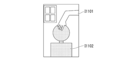
- FIG. 11 is an explanatory diagram showing an example of a real image, and includes an image I1101 of the user's hand and an image I1102 of the robot.
- FIG. 12 is an explanatory diagram illustrating an example of a human image to be combined (for example, Computer Graphics; CG).
- FIG. 13 is an explanatory diagram showing an example of an image obtained as a result of synthesis.
- the region of the robot image I1102 is replaced with the human image of FIG. 12 using the chroma key technique to synthesize the image of FIG.
- An image processing system described in Patent Literature 1 includes an image selection device that selects a CG in a form that matches the form of a real object and the positional relationship between an observer who views the real object and the real object, and a backlight image on the periphery of the CG. And a composite image generation device that generates a composite image obtained by combining the CG and the backlight image, and the composite image is displayed on the display that the observer sees so as to overlap the real object.
- An image display processing device includes an image selection device that selects a CG in a form that matches the form of a real object and the positional relationship between an observer who views the real object and the real object, and a backlight image on the periphery of the CG.
- a composite image generation device that generates a composite image obtained by combining the CG and the backlight image, and the composite image is displayed on the display that the observer sees so as to overlap the real object.
- the size of the image of the human or the like is made slightly smaller than the size of the image of the robot. Then, a post-light image is displayed in the synthesized image for the region where the image of the robot protrudes from the image of a person or the like, and the viewer's discomfort can be reduced.
- the display of the afterglow image can be made unnecessary, the viewer's uncomfortable feeling can be further reduced.
- the present invention is capable of performing image synthesis according to the shielding relationship between objects at a relatively low cost, and can further reduce the viewer's discomfort, an image synthesis system, an image synthesis system, an image synthesis method, and Provide a program.
- An image composition device obtains a real image acquisition unit that acquires a real image, and an image of a post-substitution object that is replaced with the pre-replacement object image included in the real image.
- a replacement object image acquisition unit a shielding object image region detection unit for detecting a region of a shielding object image that shields the image of the pre-substitution object in the real image, and among the images of the replacement object, A portion to be shielded that excludes a portion corresponding to the region of the image of the shielding object, and the composition of the image of the post-substitution object from which the portion corresponding to the region of the image of the shielding object is excluded from the real image
- a synthesis execution unit for performing
- An image composition device is the image composition device described above, further comprising an area dividing unit that performs edge extraction on the real image and divides the real image into regions, and the shielding object image.
- the area detection unit detects an area where at least a part of the area divided by the area dividing unit is blocking the image of the object before replacement as an area of the image of the blocking object.
- An image composition device is the above-described image composition device, and an unshielded image obtaining unit that obtains an image of the object before replacement when there is no shielding by the image of the shielded object.
- the difference between the pre-substitution object image when there is no occlusion by the occlusion object image and the pre-replacement object image excluding the portion shielded by the occlusion object image is A shielding region detection unit that detects a region shielded by the shielding object image in the object image, and the shielding object image region detection unit includes the shielding region among the regions obtained by dividing the real image. A region including a region detected by the detection unit is detected.
- An image composition device is the image composition device described above, wherein the shielded part exclusion unit is a part of the post-substitution object image that is shielded by the shield object image.
- An image of a portion corresponding to the image of the object before replacement excluding, and a portion of the image of the object after replacement excluding a portion corresponding to the image of the object before replacement and a portion corresponding to the image of the shielding object And generate an image.
- An image composition system includes an imaging device, an image composition device, and a display device, and the image composition device obtains an actual image acquired by the image capture device.
- a replacement object image obtaining unit that obtains an image of a post-replacement object that is replaced with an image of the pre-replacement object included in the real image and is combined with the real image; and
- a shielding object image region detection unit that detects a region of a shielding object image that shields an image; and a shielded part exclusion unit that excludes a portion corresponding to the shielding object image region from the replacement object image;
- a synthesis execution unit that performs the synthesis of the image of the post-replacement object excluding a portion corresponding to the area of the image of the shielding object with respect to the real image, and the display device performs the synthesis execution The image synthesized by the part is displayed.
- An image composition method is an image composition method of an image composition apparatus, wherein an actual image acquisition step of acquiring an actual image is replaced with an image of an object before replacement included in the actual image.
- a post-replacement object image acquisition step for acquiring an image of the post-replacement object to be combined with the real image, and a shielded object image region for detecting a region of the shield object image that shields the pre-substitution object image in the real image Corresponding to the area of the shielded object image with respect to the actual image, and the detection step, the shielded part exclusion step of excluding the part corresponding to the area of the shielded object image from the image of the replaced object
- a synthesis execution step of performing the synthesis of the image of the post-substitution object excluding the portion to be replaced.
- a program according to another aspect of the present invention includes a computer as an image composition device, a real image acquisition step of acquiring a real image, and a composition of the real image by replacing it with an image of a pre-replacement object included in the real image.
- a post-replacement object image acquisition step for acquiring an image of the post-replacement object
- a shielding object image region detection step for detecting a region of the shielding object image that shields the image of the pre-replacement object in the real image
- the shielded part exclusion step of excluding the part corresponding to the area of the shielded object image, and the part corresponding to the image area of the shielded object is excluded from the real image
- the present invention it is possible to perform image synthesis according to the shielding relationship between objects at a relatively low cost, and to further reduce the viewer's uncomfortable feeling.
- FIG. 4 is an explanatory diagram illustrating an example of an image that is composited with a real image by the image composition device in the embodiment.
- FIG. 3 is an explanatory diagram illustrating an example of an image generated (combined) by the image composition device in the embodiment.
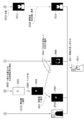
- FIG. 1 is a schematic configuration diagram showing an apparatus configuration of an image configuration system according to an embodiment of the present invention.
- an image composition system 1 includes a robot control device 100, an image composition device 200, a CG data server device 300, a robot 400, a sensor 500, a head mounted display (HMD) 600, Network 700.
- the head mounted display 600 includes an imaging device 610 and a display device 620.
- the robot control device 100, the image composition device 200, and the CG data server device 300 are connected to the network 700 and can communicate with each other.
- the robot control device 100 and the robot 400 can communicate wirelessly.
- the image composition device 200 and the sensor 500 are connected by wire and can communicate with each other.
- the image composition device 200 and the head mounted display 600 can perform wireless communication.
- the image synthesizing system 1 is a system that generates a mixed reality image, and synthesizes an image of an object that is not actually located with an actual image captured by the head mounted display 600 (an image obtained by capturing a real space).
- an image is included in the object here. Therefore, the image synthesis system 1 may synthesize an image of a person who is not actually located with the actual image captured by the head mounted display 600.
- the image is an image showing the appearance of an object.
- the robot control apparatus 100 controls and operates the robot 400 and transmits the posture information of the robot 400 to the image composition apparatus 200.
- the robot control device 100 is realized by a personal computer (PC), for example.
- the robot control apparatus 100 may be realized by a microcomputer.
- the robot 400 may move such as autonomous walking.
- the robot control device 100 controls the posture and position of the robot 400 and transmits the position information and posture information of the robot 400 to the image composition device 200.
- the robot 400 is an example of an object before replacement (an object in which an image can be replaced with another image by the image composition device 200) in the present embodiment.
- the robot 400 is provided for the image composition device 200 to calculate the position of an object that composes an image with a real image. That is, the image composition device 200 synthesizes an image obtained by replacing the robot 400 with another object.
- the appearance of the robot 400 is composed of a single color, and the image composition device 200 replaces the image of the robot 400 with another image using the chroma key technology.
- the pre-substitution object in the present embodiment is not limited to the robot. Various objects having an appearance can be used as the object before replacement.
- the sensor 500 detects the position and orientation (face orientation) of the head (head and face) of a user (an observer who wears the head-mounted display 600 and sees a composite image), and information on the detected position and orientation ( (Hereinafter referred to as “sensor information”) is output to the image composition apparatus 200.
- various sensors can be used as the sensor 500.
- the sensor 500 may irradiate infrared rays or ultrasonic waves, analyze the reflected waves, and calculate the position and posture of the user's head.
- the sensor 500 may capture an image of the user's head and calculate the position and orientation of the user's head through image recognition.
- the sensor 500 may include a gyro sensor mounted on the head mounted display 600, and the position and orientation of the user's head may be calculated based on the angle and acceleration detected by the gyro sensor.
- the method for detecting the position and orientation of the user's head is not limited to the method using the sensor 500.
- a mark as a position marker is arranged in place of the sensor 500, and the image composition device 200 uses the size and distortion of the mark image included in the image captured by the head mounted display 600 (imaging device 610).
- the position and posture of the head may be calculated.
- the image composition device 200 acquires an actual image captured by the head mounted display 600. Then, the image synthesis device 200 synthesizes an image obtained by replacing the image of the robot 400 included in the actual image with the image output from the CG data server device 300 and displays the synthesized image on the head mounted display 600.
- the image composition device 200 is realized by a personal computer, for example.
- an example of an image synthesized by the image synthesis apparatus 200 will be described with reference to FIGS.
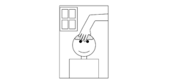
- FIG. 2 is an explanatory diagram illustrating an example of an actual image captured by the head mounted display 600.
- the real image shown in the figure is an image obtained by imaging the state where the user puts his hand on the robot 400.
- This real image includes a region A111 of the image of the robot 400, a region A112 of the image of the user's hand shielding the image of the robot 400, and a region A113 of the background image.
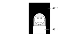
- FIG. 3 is an explanatory diagram showing an example of an image synthesized by the image synthesis device 200 into a real image.
- the image shown in the figure includes an image A211 to be combined, and the background area A212 has no background (for example, black single color).
- an object for which the image composition device 200 composes an image with a real image is referred to as a “substitution object”, and an image of the substitution object is referred to as a “substitution object image”.
- the post-replacement object is not limited to the person shown in FIG. Images of various objects whose appearance can be visually displayed can be used as replaced objects. Further, the post-replacement object may be a real object or an imaginary object.
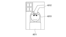
- FIG. 4 is an explanatory diagram illustrating an example of an image generated (synthesized) by the image synthesizing apparatus 200.
- the image shown in the figure is an image obtained by replacing the image of the robot 400 with the person image shown in FIG. 3 in the real image shown in FIG. 2, and the person image area A311 and the user hand image area A312. And a background image area A313.
- the image of the person shown in FIG. 4 is different in shape from the image of the robot shown in FIG. 2, but the same shielding relationship as in FIG. 2 is maintained. That is, the user's hand is blocking a part of the person (the image of the user's hand is overlapping the person's image and blocking a part of the person's image). Also, the user's hand and person are blocking a part of the background wall (the image of the user's hand and the person overlap with the image of the background wall, Shielded). In this way, the image composition device 200 replaces the image of the object before replacement with the image of the object after replacement in the real image captured by the head mounted display 600 while maintaining the shielding relationship.
- the CG data server device 300 can output images of various postures of the person who is the post-replacement object. Then, the CG data server device 300 responds to the posture of the robot viewed from the user according to the posture of the robot 400 detected by the robot control device 100 and the position and posture of the user's head detected by the sensor 500. The posture image is provided to the image composition device 200.
- the CG data server device 300 stores in advance a three-dimensional model of a person who is a post-substitution object.
- This three-dimensional model is 3DCG (3-Dimensional Computer Graphics) in which not only the front but also the side and back are made three-dimensionally.
- This three-dimensional model is equipped with a jointed skeleton, and the pose can be adjusted by setting the joint angle.
- the CG data server device 300 acquires the joint angle of the robot 400 and adjusts the pose of the three-dimensional model of the person to a pose corresponding to the joint angle.
- the CG data server device 300 acquires a snapshot (two-dimensional image) of the person (substitution object) whose size and orientation are adjusted based on the positional relationship between the robot 400 and the user.
- the CG data server device 300 can output images of various postures of the robot 400 (an object before replacement) as an unshielded image (hereinafter referred to as “complete image”). Specifically, the CG data server device 300 stores a three-dimensional model of the robot 400 in advance. Then, the CG data server device 300, as in the case of a snapshot of a person (substitution object), generates a complete image snapshot (two-dimensional image) of the robot 400 with the joint angle of the robot 400, the robot 400 and the user. Acquired based on the positional relationship. The complete image of the robot 400 (pre-substitution object) output by the CG data server device 300 is used when the image composition device 200 generates a composite image, as will be described later. Hereinafter, the complete image of the object before replacement is referred to as an “non-shielded image”.
- the CG data server device 300 is realized by a personal computer, for example.
- the head mounted display 600 captures a user's visual field image with the imaging device 610 and transmits it to the image composition device 200, and displays the composite image from the image composition device 200 on the display device 620.
- a case where a video see-through type head mounted display is used as the head mounted display 600 will be described, but the present invention is not limited thereto.
- an optical see-through head mounted display may be used as the head mounted display 600.
- the head mounted display 600 displays a composite image based on an external image captured by the imaging device on the display device.
- the head-mounted display 600 blocks a part of the light beam from the outside and replaces it with a light beam indicating the image of the replaced object, and the other part (the area of the image of the shielded object or the area of the background image).
- a composite image based on the actual image may be displayed by transmitting light rays from the outside.
- the network 700 is a communication network such as a LAN (Local Area Network), for example, and mediates communication among the robot control device 100, the image composition device 200, and the CG data server device 300.
- this embodiment does not depend on the communication form of each part. Accordingly, various communication methods can be used as the communication method of each unit, not limited to that shown in FIG.
- the image composition device 200 and the sensor 500 may communicate wirelessly.
- the robot control device 100 and the robot 400 may be connected by wire to perform communication.
- the image synthesizing apparatus 200 and the head mounted display 600 may be connected to each other via a wired communication.
- the robot control apparatus 100 and the image composition apparatus 200 may communicate with each other directly or through a wired or wireless connection without using the network 700.
- the image composition device 200 and the CG data server device 300 may communicate with each other directly or through a wired or wireless connection without going through the network 700. Further, the robot control device 100 and the robot 400, the image composition device 200 and the sensor 500, or the image composition device 200 and the head mounted display 600 may communicate with each other via the network 700. In this embodiment, the robot control device 100, the image composition device 200, and the CG data server device 300 are realized by separate devices, but two or all three of them are 1 It may be realized by one device (for example, one personal computer).
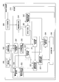
- FIG. 5 is a schematic block diagram illustrating a functional configuration of the image composition device 200.
- the image composition device 200 includes a network communication unit 201, a sensor information acquisition unit 202, an HMD communication unit 203, and a control unit 210.
- the control unit 210 includes a post-substitution object image acquisition unit 221, a post-substitution object image mask processing unit 222, a non-shielding image acquisition unit 231, a non-shielding image masking processing unit 232, and a surrounding image acquisition unit 233.
- the network communication unit 201 is connected to the network 700 and communicates with the robot control device 100 and the CG data server device 300 to acquire various data.
- the sensor information acquisition unit 202 communicates with the sensor 500 and acquires sensor information.
- the HMD communication unit 203 communicates with the head mounted display 600 to acquire real image data captured by the image capturing device 610 and transmit composite image data to be displayed on the display device 620.
- the control unit 210 controls each unit of the image composition device 200 and executes image composition.
- the control unit 210 is realized by, for example, a CPU (Central Processing Unit) that is included in a personal computer serving as the image composition device 200 reading and executing a program from a storage device included in the personal computer.
- Each unit of the control unit 210 is configured as a module (for example, a subroutine) of a program executed by the control unit 210, for example.
- the post-substitution object image acquisition unit 221 acquires the post-substitution object image that is to be replaced with the pre-substitution object image included in the real image and synthesized with the real image. Specifically, the post-replacement object image acquisition unit 221 first calculates the posture of the robot 400 as viewed from the user based on the sensor information acquired by the sensor information acquisition unit 202. Then, the post-replacement object image acquisition unit 221 transmits the calculated posture information to the CG data server device 300 via the network communication unit 201, and the post-replacement object image (in the present embodiment, the human object image). Image) is acquired from the CG data server device 300.
- the post-replacement object image in the present embodiment, the human object image. Image
- the post-substitution object image acquisition unit 221 performs alignment and size adjustment (enlargement / reduction) on the acquired person image, and superimposes the image on the robot 400 in the actual image. More specifically, the post-substitution object image acquisition unit 221 sets the size of the person's image to the same size as the image of the robot 400 based on the dimensions of a part of the body such as height or shoulder width, and the person in the space The human images are overlapped so that the coordinates of the person coincide with the coordinates of the robot 400. By using a robot that is thinner (slightly smaller) than the replaced object as the robot 400, it is possible to superimpose a human image on the entire image of the robot 400 (hide the image of the robot 400).
- the post-substitution object image mask processing unit 222 generates a mask corresponding to the post-substitution object image acquired by the post-substitution object image acquisition unit 221 and applies the generated mask to the actual image.
- the non-shielding image acquisition unit 231 acquires an image of the object before replacement when there is no shielding by the image of the shielding object. Specifically, as described above, the CG data server device 300 can output complete images of various postures of the robot 400 (object before replacement). Similarly to the post-substitution object image acquisition unit 221, the non-shielding image acquisition unit 231 calculates the posture of the robot 400 as viewed from the user based on the sensor information acquired by the sensor information acquisition unit 202.
- the unobstructed image acquisition unit 231 transmits the calculated posture information to the CG data server device 300 via the network communication unit 201, and the complete image of the robot 400 corresponding to the posture is transmitted to the CG data server. Obtained from the device 300. Further, the non-shielding image acquisition unit 231 performs alignment and size adjustment on the acquired image of the robot 400 and superimposes it on the image of the robot 400 in the real image (other than the part shielded by the user's hand). Are superimposed so that the images match).
- the non-shielding image masking processing unit 232 masks the pre-substitution object image acquired by the non-shielding image acquisition unit 231.
- the surrounding image acquisition unit 233 applies the mask generated by the non-shielding image masking processing unit 232 to the post-replacement object image acquired by the post-replacement object image acquisition unit 221, thereby replacing the replacement object image.
- the real image acquisition unit 241 acquires a real image captured by the imaging device 610 via the HMD communication unit 203.
- the pre-replacement object image region processing unit 242 extracts a region (monochromatic region) of the pre-replacement object image included in the real image acquired by the real image acquisition unit 241 and generates a mask based on the extracted region.
- the region dividing unit 243 performs edge extraction (differential processing) on the actual image to divide the actual image into regions. By performing edge extraction by the area dividing unit 243, even when the color of the same object changes due to gradation or shade, the image area of the same object can be detected as the same area.
- the shielding area detection unit 251 obtains a difference between the image of the object before replacement when there is no shielding by the image of the shielding object and the image of the object before replacement excluding the portion shielded by the image of the shielding object, thereby performing the replacement. A region that is shielded by the image of the shielding object (in the example of FIG. 2, a region that is shielded by the image of the user's hand) is detected.
- the shielding object image area detection unit 252 detects the area of the shielding object image that shields the image of the object before replacement in the real image.
- the shielding object image region detection unit 252 includes a region in which at least a part of the region divided by the region dividing unit 243 blocks the image of the object before replacement (in the example of FIG. 2, the user's hand). ) Is detected as an image area of the shielding object.
- the shielded object image region detection unit 252 detects a region shielded by the shielded object image among the pre-substitution object images detected by the shield region detection unit 251 among the regions obtained by dividing the actual image. Detect the containing area.
- the shielded object image region processing unit 253 performs extraction from a real image (generation of a partial image for synthesis) and masking processing on the shielded object image detected by the shielded object image region detection unit 252.
- the shielded part exclusion unit 254 excludes a part corresponding to the area of the shielded object image from the replaced object image.
- the portion corresponding to the area of the image of the shielded object is the portion of the image of the replaced object that is shielded by the image of the shielded object in the combined image.
- the shielded part exclusion unit 254 corresponds to the image area of the shielded object for each of the image of the part that replaces the image of the object before replacement and the surrounding image among the images of the replaced object. An image excluding the part is generated. That is, the occluded part exclusion unit 254 includes an image of a part corresponding to an image of the object before replacement excluding a part shielded by the image of the shielded object and an image of the object after replacement of the image of the replaced object. An image of a part excluding a part corresponding to the image of the object before replacement and a part corresponding to the image of the shielding object is generated.
- the composition execution unit 255 synthesizes the image of the post-replacement object, excluding the portion corresponding to the image area of the shielding object, with respect to the actual image. A specific example of the process performed by the composition execution unit 255 will be described later.
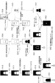
- FIGS. FIG. 6 and FIG. 7 are explanatory diagrams showing a processing procedure in which the image composition device 200 generates a composite image.
- the image composition apparatus 200 performs the processing illustrated in FIG.
- the post-replacement object image acquisition unit 221 acquires the post-replacement object image P110 (a person image in the present embodiment) from the CG data server device 300
- the non-shielding image acquisition unit 231 acquires the CG data server device.
- An unshielded image P210 (in this embodiment, a complete image of the robot 400) is acquired from 300.
- the post-substitution object image mask processing unit 222 first monochromaticizes the post-substitution object image P110 acquired by the post-substitution object image acquisition unit 221 to generate an image P111 (step S111). ). Next, the post-replacement object image mask processing unit 222 extracts a monochrome region from the monochromatic image P111 and generates an image P112 (step S112). The image P112 is divided into a replacement object image region and a background region (region set as no background in the replacement object image P110).
- the post-substitution object image mask processing unit 222 masks the image P112 to generate a mask P113 (step S113).
- the mask P113 the background area is masked (set to have no image), and the image area of the post-replacement object is unmasked (set to have an image).
- the method by which the image composition device 200 acquires the mask P113 is not limited to the method in which the processes in steps S111 to S113 are performed.
- the CG data server device 300 synthesizes a mask corresponding to the image together with the image of the replaced object or stores a CG image of a person (substitute object) painted in a single color in advance. A mask may be generated from the above.
- the image composition device 200 may acquire a mask from the CG data server device 300 together with the image of the replaced object.
- the post-replacement object image mask processing unit 222 inverts the mask P113 to generate a mask P121 (step S121). That is, in the mask P121, the image area of the post-replacement object is masked, and the background area is not masked. Then, the post-substitution object image mask processing unit 222 applies the mask P121 to the real image P310 to generate the image P122 (step S122).
- This image P122 is used as a part of a composite image generated by the image composition device 200.
- the image P122 is an image of a portion of the real image P310 that is not affected by the image of the replaced object. Therefore, the image composition device 200 (composition execution unit 255) can compose the image P122 as it is without the need to detect the shielding relationship.
- the non-shielding image masking processing unit 232 first has a single color (the color colored by the robot 400 for chroma key processing) with respect to the non-shielding image P210 acquired by the non-shielding image acquisition unit 231. ) Are extracted to generate an image P211 (step S211).
- the image P211 is divided into a non-shielded image region (a complete image region of the robot 400 as an object before replacement) and a background region.
- the non-shielding image masking processing unit 232 masks the image P211 to generate a mask P212 (step S212).
- the mask P212 the non-shielded image area is masked, and the background area is unmasked.
- the surrounding image acquisition unit 233 applies the mask P212 to the post-replacement object image P221 to generate the image P221 (step S221).
- the image P221 is an image of a surrounding area excluding an area corresponding to the image of the object before replacement, from the image of the object after replacement. This surrounding area is an area in which the occlusion relation is not shown in the real image, and the image composition device 200 needs to detect the occlusion relation with the real object.
- the shielding area detection unit 251 generates the mask P231 by inverting the mask P212 (step S231). That is, in the mask P231, the background region is masked, and the non-shielded image region is unmasked.
- the pre-substitution object image region processing unit 242 extracts a single color region from the actual image P310 acquired by the actual image acquisition unit 241 and acquires the image P311 (step S311). Specifically, the pre-replacement object image region processing unit 242 extracts a color region colored by the robot 400 for chroma key processing from the real image P310, thereby shielding the pre-replacement object image. Detect missing areas. Next, the pre-substitution object image region processing unit 242 masks the image P311 and generates a mask P312 (step S312). In the mask P312, the area of the unshielded portion of the image of the object before replacement is masked, and the other areas (the background area and the image area of the shielded object) are not masked.
- the pre-substitution object image region processing unit 242 inverts the mask P312 to generate a mask P313 (step S313). That is, in the mask P313, the region of the unshielded portion of the image of the object before replacement is not masked, and the other regions (background region and shielded object image region) are masked.
- the shielded part excluding unit 254 applies the mask P313 to the post-replacement object image P110 to generate the image P314.
- the image P314 is an image of an area where the occlusion relationship is indicated in the real image (an area not affected by the occlusion object). Therefore, the image composition device 200 (composition execution unit 255) can synthesize the image P314 as it is without further need to detect the shielding relationship.
- the region dividing unit 243 acquires an image P322 by extracting an edge from the real image P310 acquired by the real image acquisition unit 241 (step S321). Then, the region dividing unit 243 refers to the single-color region image P311 generated by the pre-replacement object image region processing unit 242 (step S322), ignores (deletes) the edge in the single-color region in the edge image P322, An image P323 is generated (step S323).
- the shielding region detection unit 251 adds the mask P231 generated in step S231 and the mask P312 generated by the pre-substitution object image region processing unit 242 to generate a mask P421 (step S421).
- the mask P421 only the part where the image of the object before replacement is shielded by the image of the shielding object is set as a non-mask, and other areas (the area where the image of the object before replacement is not shielded and the background area) are set. ) Is masked. That is, the shielding area detection unit 251 generates a mask P421 to detect a portion of the real image P310 where the image of the object before replacement is shielded by the image of the shielding object.
- the shielded object image region detection unit 252 applies the mask P113 generated by the post-substitution object image mask processing unit 222 to the image P323 (divided region image) generated by the region dividing unit 243, and generates an image P411.
- the image P411 is an image showing the region division of a portion (a portion corresponding to the image of the replaced object) in the actual image P310 where the shielding relationship may be a problem.
- the shielding object image area detection unit 252 determines whether or not each area of the image P411 overlaps with the mask P421 (non-mask area in the area) (step S422). Then, the shielding object image area detection unit 252 extracts the entire area that partially overlaps the mask P421 (the non-mask area in the area) of each area of the image P411, and generates the image P423 (step S423). ). That is, the shielding object image region detection unit 252 detects the region of the shielding object image (of the shielding object image region (of which the shielding object detection unit 251 detects the shielding object image). The portion corresponding to the image of the post-substitution object) is detected.
- the shielding object image region processing unit 253 generates a mask P424 by masking the image P423 (step S424).
- mask P424 the area of the image of the shielded object (of the part corresponding to the image of the replaced object) is not masked, and the other area (of the area of the image of the replaced object is not shielded by the image of the shielded object). Part and background area) are masked.
- the shielding object image region processing unit 253 applies the mask P424 to the real image P310 to generate the image P431 (step S431).
- the image P431 is an image of a shielding object (a portion corresponding to the image of the replaced object).
- the shielded part excluding unit 254 inverts the mask P424 and applies it to the image P221 generated by the surrounding image acquisition unit 233 to generate the image P441 (step S441).
- the image P441 is an image obtained by excluding the portion shielded by the shielding object from the surrounding portion of the image of the replaced object. That is, when the image P441 and the image P314 are added together, an image of a portion of the post-substitution object image that is not shielded by the shielding object is obtained.
- the composition execution unit 255 adds the image P122, the image P314, the image P431, and the image P441 to generate a composite image P511 (step S511).
- An image showing can be obtained.
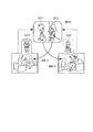
- FIG. 8 is an explanatory diagram showing an example of a first mode to which the image composition system 1 is applied.
- the image composition system 1 (CG data server device 300) synthesizes image data of a plurality of characters as the replaced object.
- the CG data server device 300 stores a three-dimensional model in advance for each of the four characters C111 to C114, and snapshots (viewed from arbitrary viewpoints of the user) of images of various postures. 2D image) can be output.
- the image composition system 1 combines the image of the character selected by the user (character C111 in the example of FIG. 8) with the actual image (replaces the image of the robot 400) and presents it to the user.
- the robot 400 may be automatically steered, or another person may steer the robot 400 by remote control.
- the CG data server device 300 may be in a sharable form such as on the Internet.
- FIG. 9 is an explanatory diagram illustrating an example of a second mode to which the image composition system 1 is applied.
- the user and the conversation partner log in to an avatar service (for example, a virtual world service), and perform a conversation between avatars.
- the image composition system 1 composes an image of the character C211 as an avatar of the conversation partner with a real image and presents it to the user.
- the conversation partner remotely operates the robot 400 using a personal computer as the robot control device 100.
- the user can enjoy the conversation with the avatar of the conversation partner with a sense of reality.
- the world W211 in which the character C211 as the avatar of the conversation partner and the user (its avatar) interact may be a virtual world or a real space such as a user's room.
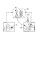
- FIG. 10 is an explanatory diagram showing an example of a third mode to which the image composition system 1 is applied.
- the user and the conversation partner log in to the avatar service (for example, virtual world service) and perform a conversation between the avatars (avatars C311 and C312).
- avatar service for example, virtual world service
- avatars C311 and C312 the avatar service
- both the user and the conversation partner possess robots (robots 400-1 and 400-2).
- the image synthesis system 1 synthesizes images as if each other's avatar was transferred to the partner robot. Thereby, the user and the conversation partner can enjoy the conversation between the avatars with a greater sense of reality.
- the world W311 in which the conversation partner avatar C311 and the user avatar C312 interact may be a virtual world or a real space such as each other's room (the user's room and the conversation partner's room). .
- the image composition system 1 can be used for various purposes other than entertainment such as a character experience and dialogue using an avatar. For example, you can build educational content such as rock stars appearing and teaching guitar. Alternatively, as a medical use, the image synthesis system 1 may be used for the treatment of human phobia. It is also possible to use the image composition system 1 as a simulated patient for training a doctor's response to the patient.
- the shielding object image region detection unit 252 detects the region of the shielding object image.
- the shielded part exclusion unit 254 excludes a part corresponding to the area of the shielded object image from the replaced object image.
- the composition execution unit 255 synthesizes the image of the replaced object with the real image (in the example of FIG. 7, the images P122 and P431) excluding the part corresponding to the image area of the shielding object.
- the image composition device 200 can grasp the shielding relationship between the image of the object after replacement and the image of the shielding object by grasping the shielding relationship between the image of the object before replacement and the image of the shielding object.
- the image composition system 1 it is possible to perform image composition in accordance with the shielding relation of objects at a relatively low cost without requiring a device such as TOF.
- the image composition system 1 generates a composite image without using color information such as the color of the user's hand.
- the image composition system 1 is highly versatile. Further, in the image composition system 1, it is not necessary to make the pre-substitution object such as a robot larger than the post-substitution object such as a person. Therefore, the degree of freedom in designing the object before replacement such as a robot is high. Also, the post-replacement object (image to be combined) does not require shape restrictions such as a shortcut in accordance with the shape of the robot. That is, the degree of freedom of shape for the replaced object is increased.
- the area dividing unit 243 performs edge extraction on the actual image and divides the actual image into areas. Then, the shielding object image region detection unit 252 detects, as a region of the shielding object image, a region where at least a part of the region divided by the region dividing unit 243 shields the image of the object before replacement.
- the obscured object image region detection unit 252 can more accurately grasp the occluding relationship between the image of the replaced object in the composite image and the occluding object.
- the shielding area detection unit 251 obtains a difference between the image of the object before replacement when there is no shielding by the image of the shielding object and the image of the object before replacement excluding the portion shielded by the image of the shielding object. And detecting a region shielded by the image of the shielding object from the image of the object before replacement. Then, the shielding object image region detection unit 252 detects a region including the region detected by the shielding region detection unit 251 among the regions obtained by dividing the actual image. As a result, the image composition system 1 performs simple image processing and determination such as addition of masks in step S421 in FIGS. 6 to 7 and detection of overlapping regions in steps S422 to S423. The shielding relationship can be detected.
- the shielded part exclusion unit 254 includes an image of a part corresponding to the image of the object before replacement excluding a part shielded by the image of the shielded object, and an image of the object after replacement of the image of the replaced object.
- An image of a part excluding a part corresponding to the image of the object before replacement and a part corresponding to the image of the shielding object is generated.
- the shielded part excluding unit 254 may detect the shielding relationship with the shielding object for the area corresponding to the periphery of the image of the object before replacement in the area of the image of the object after replacement.
- the scope of application of the present invention is not limited to the configuration using the above-described head mounted display.
- the present invention can be applied to various configurations in which a front-rear relationship between a robot and an object is generated, such as an image displayed on a fixed screen by a fixed camera.
- a smartphone or a display of a personal computer can be used as the display device in the present invention.
- a program for realizing all or part of the functions of the control unit 210 is recorded on a computer-readable recording medium, and the program recorded on the recording medium is read into a computer system and executed. You may perform the process of.
- the “computer system” includes an OS and hardware such as peripheral devices. Further, the “computer system” includes a homepage providing environment (or display environment) if a WWW system is used.
- the “computer-readable recording medium” refers to a storage device such as a flexible medium, a magneto-optical disk, a portable medium such as a ROM or a CD-ROM, and a hard disk incorporated in a computer system.
- the “computer-readable recording medium” dynamically holds a program for a short time like a communication line when transmitting a program via a network such as the Internet or a communication line such as a telephone line.
- a volatile memory in a computer system serving as a server or a client in that case and a program that holds a program for a certain period of time are also included.
- the program may be a program for realizing a part of the functions described above, and may be a program capable of realizing the functions described above in combination with a program already recorded in a computer system.
- the present invention provides a real image acquisition unit that acquires a real image, and a post-substitution object image acquisition unit that acquires an image of a post-replacement object that is combined with the real image and replaced with the pre-substitution object image included in the real image
- a shielding object image region detection unit for detecting a region of a shielding object image that shields the image of the object before replacement in the real image, and a region of the shielding object image among the images of the replacement object.
- the present invention relates to an image synthesizing apparatus. According to the present invention, it is possible to perform image synthesis according to the shielding relationship between objects at a relatively low cost, and to further reduce the discomfort of the observer.
Landscapes
- Engineering & Computer Science (AREA)
- Multimedia (AREA)
- Human Computer Interaction (AREA)
- General Physics & Mathematics (AREA)
- Software Systems (AREA)
- Physics & Mathematics (AREA)
- General Engineering & Computer Science (AREA)
- Theoretical Computer Science (AREA)
- Computer Hardware Design (AREA)
- Computer Graphics (AREA)
- Environmental & Geological Engineering (AREA)
- Radar, Positioning & Navigation (AREA)
- Processing Or Creating Images (AREA)
- Image Processing (AREA)
- Testing, Inspecting, Measuring Of Stereoscopic Televisions And Televisions (AREA)
Priority Applications (1)
| Application Number | Priority Date | Filing Date | Title |
|---|---|---|---|
| US14/417,697 US9449394B2 (en) | 2012-07-30 | 2013-07-30 | Image synthesis device, image synthesis system, image synthesis method and program |
Applications Claiming Priority (2)
| Application Number | Priority Date | Filing Date | Title |
|---|---|---|---|
| JP2012168362A JP5791082B2 (ja) | 2012-07-30 | 2012-07-30 | 画像合成装置、画像合成システム、画像合成方法およびプログラム |
| JP2012-168362 | 2012-07-30 |
Publications (1)
| Publication Number | Publication Date |
|---|---|
| WO2014021326A1 true WO2014021326A1 (ja) | 2014-02-06 |
Family
ID=50027999
Family Applications (1)
| Application Number | Title | Priority Date | Filing Date |
|---|---|---|---|
| PCT/JP2013/070624 Ceased WO2014021326A1 (ja) | 2012-07-30 | 2013-07-30 | 画像合成装置、画像合成システム、画像合成方法およびプログラム |
Country Status (3)
| Country | Link |
|---|---|
| US (1) | US9449394B2 (enExample) |
| JP (1) | JP5791082B2 (enExample) |
| WO (1) | WO2014021326A1 (enExample) |
Cited By (2)
| Publication number | Priority date | Publication date | Assignee | Title |
|---|---|---|---|---|
| CN109035185A (zh) * | 2018-06-29 | 2018-12-18 | 努比亚技术有限公司 | 一种图像处理方法及终端 |
| WO2024127819A1 (ja) * | 2022-12-14 | 2024-06-20 | 株式会社デンソー | 処理システム、処理方法、処理プログラム |
Families Citing this family (16)
| Publication number | Priority date | Publication date | Assignee | Title |
|---|---|---|---|---|
| JP2015119373A (ja) * | 2013-12-19 | 2015-06-25 | ソニー株式会社 | 画像処理装置および方法、並びにプログラム |
| JP6596883B2 (ja) * | 2015-03-31 | 2019-10-30 | ソニー株式会社 | ヘッドマウントディスプレイ及びヘッドマウントディスプレイの制御方法、並びにコンピューター・プログラム |
| WO2018136072A1 (en) * | 2017-01-19 | 2018-07-26 | Hewlett-Packard Development Company, L.P. | Telepresence |
| JP6845072B2 (ja) * | 2017-04-21 | 2021-03-17 | ファナック株式会社 | 工場設備の保守支援装置及び保守支援システム |
| JP7023971B2 (ja) * | 2017-09-29 | 2022-02-22 | 本田技研工業株式会社 | サービス提供システム、サービス提供方法およびサービス提供システム用管理装置 |
| JP6564484B1 (ja) * | 2018-03-23 | 2019-08-21 | 国立大学法人電気通信大学 | 同室感コミュニケーションシステム |
| JP6688337B2 (ja) * | 2018-06-06 | 2020-04-28 | 任天堂株式会社 | 情報処理プログラム、情報処理システム、情報処理装置および情報処理方法 |
| US10884525B1 (en) | 2019-04-23 | 2021-01-05 | Lockheed Martin Corporation | Interactive mixed masking system, method and computer program product for a simulator |
| CN110070540B (zh) * | 2019-04-28 | 2023-01-10 | 腾讯科技(深圳)有限公司 | 图像生成方法、装置、计算机设备及存储介质 |
| CN114206560A (zh) * | 2019-06-05 | 2022-03-18 | 超乎想象股份有限公司 | 移动性代理 |
| US11107280B1 (en) * | 2020-02-28 | 2021-08-31 | Facebook Technologies, Llc | Occlusion of virtual objects in augmented reality by physical objects |
| JP7319215B2 (ja) * | 2020-03-06 | 2023-08-01 | Kddi株式会社 | 情報システム、端末及びプログラム |
| US11763508B2 (en) | 2020-11-11 | 2023-09-19 | Sony Interactive Entertainment Inc. | Disambiguation of poses |
| US11263796B1 (en) * | 2020-11-11 | 2022-03-01 | Sony Interactive Entertainment Inc. | Binocular pose prediction |
| JP7429633B2 (ja) * | 2020-12-08 | 2024-02-08 | Kddi株式会社 | 情報処理システム、端末、サーバ及びプログラム |
| US20240027617A1 (en) * | 2020-12-10 | 2024-01-25 | Maxell, Ltd. | Portable terminal and electronic glasses |
Citations (4)
| Publication number | Priority date | Publication date | Assignee | Title |
|---|---|---|---|---|
| WO2003063086A1 (fr) * | 2002-01-23 | 2003-07-31 | Michihiko Shouji | Systeme de traitement d'images, appareil de traitement d'images, et appareil d'affichage |
| JP2004234253A (ja) * | 2003-01-29 | 2004-08-19 | Canon Inc | 複合現実感呈示方法 |
| JP2005107969A (ja) * | 2003-09-30 | 2005-04-21 | Canon Inc | 画像表示方法及び画像表示システム |
| JP2009134693A (ja) * | 2007-10-30 | 2009-06-18 | Canon Inc | 画像処理装置、画像処理方法 |
Family Cites Families (8)
| Publication number | Priority date | Publication date | Assignee | Title |
|---|---|---|---|---|
| JP3037383B2 (ja) * | 1990-09-03 | 2000-04-24 | キヤノン株式会社 | 画像処理システム及びその方法 |
| US6317513B2 (en) * | 1996-12-19 | 2001-11-13 | Cognex Corporation | Method and apparatus for inspecting solder paste using geometric constraints |
| JP2003179738A (ja) * | 2001-12-11 | 2003-06-27 | Minolta Co Ltd | 画像処理装置 |
| JP4167590B2 (ja) * | 2003-12-22 | 2008-10-15 | 株式会社東芝 | 画像処理方法 |
| US7907791B2 (en) * | 2006-11-27 | 2011-03-15 | Tessera International, Inc. | Processing of mosaic images |
| US8144953B2 (en) * | 2007-09-11 | 2012-03-27 | Siemens Medical Solutions Usa, Inc. | Multi-scale analysis of signal enhancement in breast MRI |
| TWI417813B (zh) * | 2010-12-16 | 2013-12-01 | Ind Tech Res Inst | 可串接式相機竄改偵測收發器模組 |
| GB2514495B (en) * | 2012-01-31 | 2015-04-22 | Panasonic Ip Man Co Ltd | Image processing device and image processing method |
-
2012
- 2012-07-30 JP JP2012168362A patent/JP5791082B2/ja not_active Expired - Fee Related
-
2013
- 2013-07-30 WO PCT/JP2013/070624 patent/WO2014021326A1/ja not_active Ceased
- 2013-07-30 US US14/417,697 patent/US9449394B2/en not_active Expired - Fee Related
Patent Citations (4)
| Publication number | Priority date | Publication date | Assignee | Title |
|---|---|---|---|---|
| WO2003063086A1 (fr) * | 2002-01-23 | 2003-07-31 | Michihiko Shouji | Systeme de traitement d'images, appareil de traitement d'images, et appareil d'affichage |
| JP2004234253A (ja) * | 2003-01-29 | 2004-08-19 | Canon Inc | 複合現実感呈示方法 |
| JP2005107969A (ja) * | 2003-09-30 | 2005-04-21 | Canon Inc | 画像表示方法及び画像表示システム |
| JP2009134693A (ja) * | 2007-10-30 | 2009-06-18 | Canon Inc | 画像処理装置、画像処理方法 |
Cited By (2)
| Publication number | Priority date | Publication date | Assignee | Title |
|---|---|---|---|---|
| CN109035185A (zh) * | 2018-06-29 | 2018-12-18 | 努比亚技术有限公司 | 一种图像处理方法及终端 |
| WO2024127819A1 (ja) * | 2022-12-14 | 2024-06-20 | 株式会社デンソー | 処理システム、処理方法、処理プログラム |
Also Published As
| Publication number | Publication date |
|---|---|
| JP5791082B2 (ja) | 2015-10-07 |
| US20150193940A1 (en) | 2015-07-09 |
| US9449394B2 (en) | 2016-09-20 |
| JP2014026590A (ja) | 2014-02-06 |
Similar Documents
| Publication | Publication Date | Title |
|---|---|---|
| JP5791082B2 (ja) | 画像合成装置、画像合成システム、画像合成方法およびプログラム | |
| EP4058870B1 (en) | Co-located pose estimation in a shared artificial reality environment | |
| US20250044076A1 (en) | Information processing apparatus, information processing method, and recording medium | |
| US11577159B2 (en) | Realistic virtual/augmented/mixed reality viewing and interactions | |
| JP4950834B2 (ja) | 画像処理装置、画像処理方法 | |
| EP3496047B1 (en) | Image distribution system | |
| KR101687017B1 (ko) | 머리 착용형 컬러 깊이 카메라를 활용한 손 위치 추정 장치 및 방법, 이를 이용한 맨 손 상호작용 시스템 | |
| JP6364022B2 (ja) | 多重現実環境における役割切り替えのためのシステムおよび方法 | |
| CN109801379A (zh) | 通用的增强现实眼镜及其标定方法 | |
| US9858475B2 (en) | Method and system of hand segmentation and overlay using depth data | |
| JP7262973B2 (ja) | 情報処理装置、情報処理方法及びプログラム | |
| KR102188313B1 (ko) | Vr을 이용한 다기종 비행 훈련 시뮬레이터 | |
| WO2016017245A1 (ja) | 情報処理装置及び情報処理方法、並びに画像表示システム | |
| CN101743567A (zh) | 虚拟互动式出席系统及方法 | |
| JP2010128986A (ja) | 複合現実感提示システムと仮想光源の輝度調整方法 | |
| JP6312512B2 (ja) | 遠隔見守りシステム | |
| Mihelj et al. | Introduction to virtual reality | |
| KR20160000986A (ko) | 혼합현실을 이용한 가상현실 시스템 및 그 구현방법 | |
| Saraiji et al. | Real-time egocentric superimposition of operator's own body on telexistence avatar in virtual environment | |
| RU101237U1 (ru) | Система виртуального присутствия | |
| CN219302988U (zh) | 一种增强现实装置 | |
| JP7760355B2 (ja) | 情報処理装置、情報処理方法およびプログラム | |
| JP2015172900A (ja) | 画像呈示装置及びこれに用いるマスク生成装置 |
Legal Events
| Date | Code | Title | Description |
|---|---|---|---|
| 121 | Ep: the epo has been informed by wipo that ep was designated in this application |
Ref document number: 13825312 Country of ref document: EP Kind code of ref document: A1 |
|
| WWE | Wipo information: entry into national phase |
Ref document number: 14417697 Country of ref document: US |
|
| NENP | Non-entry into the national phase |
Ref country code: DE |
|
| 122 | Ep: pct application non-entry in european phase |
Ref document number: 13825312 Country of ref document: EP Kind code of ref document: A1 |