WO2014021296A1 - 光記録システムおよびディスクカートリッジ - Google Patents
光記録システムおよびディスクカートリッジ Download PDFInfo
- Publication number
- WO2014021296A1 WO2014021296A1 PCT/JP2013/070545 JP2013070545W WO2014021296A1 WO 2014021296 A1 WO2014021296 A1 WO 2014021296A1 JP 2013070545 W JP2013070545 W JP 2013070545W WO 2014021296 A1 WO2014021296 A1 WO 2014021296A1
- Authority
- WO
- WIPO (PCT)
- Prior art keywords
- recording
- optical
- disk
- disc
- cartridge
- Prior art date
- Legal status (The legal status is an assumption and is not a legal conclusion. Google has not performed a legal analysis and makes no representation as to the accuracy of the status listed.)
- Ceased
Links
Images




Classifications
-
- G—PHYSICS
- G11—INFORMATION STORAGE
- G11B—INFORMATION STORAGE BASED ON RELATIVE MOVEMENT BETWEEN RECORD CARRIER AND TRANSDUCER
- G11B15/00—Driving, starting or stopping record carriers of filamentary or web form; Driving both such record carriers and heads; Guiding such record carriers or containers therefor; Control thereof; Control of operating function
- G11B15/675—Guiding containers, e.g. loading, ejecting cassettes
- G11B15/68—Automatic cassette changing arrangements; automatic tape changing arrangements
-
- G—PHYSICS
- G11—INFORMATION STORAGE
- G11B—INFORMATION STORAGE BASED ON RELATIVE MOVEMENT BETWEEN RECORD CARRIER AND TRANSDUCER
- G11B17/00—Guiding record carriers not specifically of filamentary or web form, or of supports therefor
- G11B17/22—Guiding record carriers not specifically of filamentary or web form, or of supports therefor from random access magazine of disc records
Definitions
- the present invention relates to an optical recording system capable of recording a plurality of optical discs each having one or more recording layers on a plurality of optical discs taken out from a detachable disc cartridge, and the disc cartridge.
- the recording layer is multilayered.
- track king control at the time of recording or reproducing data on a recording layer is performed using a guide track provided in a layer different from the recording layer.
- tracking control is performed on a guide track layer provided with a guide track having a groove structure using light having a wavelength of 390 nm to 420 nm (blue), and one recording layer among a plurality of recording layers is 650 nm to 680 nm.
- an optical drive device that performs recording using light of the wavelength (red) (for example, Patent Document 1).
- a unique ID may be recorded on each optical disc so that the optical recording system can identify the optical disc.
- the disc ID recorded in the BCA (Burst Cutting Cutting Area) of the optical disc is read by the optical pickup unit, and is obtained for the optical disc in the nonvolatile memory in the recording / reproducing apparatus. It is stored in association with a control value for focus servo, a control value for tracking servo, a laser control value, and the like.
- the recording / reproducing apparatus reads the control values stored in association with the disk ID from the nonvolatile memory, and uses these control values to focus servo, Adjust tracking servo, laser beam intensity, etc.
- this Patent Document 2 also describes that a disk ID of the optical disk is printed with a barcode, a QR (registered trademark) code, or the like on a cartridge containing the optical disk.
- an optical recording system capable of performing recording / reproduction on a plurality of multilayer optical discs in parallel using a plurality of disc drives has been studied.
- a plurality of multilayer optical discs are introduced into the system in a form of being integrally housed in a disc cartridge.
- each multilayer optical disk is automatically conveyed from a disk cartridge so as to be loaded into a separate disk drive.
- a plurality of multilayer optical discs in units of disc cartridges are used as one continuous recording space for the purpose of, for example, RAID (RedundantunArrays of Inexpensive Disks).
- RAID RedundantunArrays of Inexpensive Disks
- the multi-layer optical disk is replaced due to, for example, a mechanical trouble in the optical recording system or a human error outside the system. Or missing parts may occur.
- an object of the present invention is to provide an optical recording system capable of realizing logical association between a disc cartridge and a plurality of optical discs accommodated therein, and improving user convenience. It is to provide a disk cartridge.
- an optical recording system is a disc cartridge in which a plurality of optical discs can be attached and detached and provided with a recording unit, the optical disc of the disc cartridge and the recording Information for associating the plurality of optical discs and the disc cartridge is recorded in advance in any one of the sections, and the disc recording can be recorded on and read from the plurality of optical discs taken out from the disc cartridge
- the information is read by the reproducing unit, the access unit capable of recording and reading at least one of the recording unit of the disc cartridge, and the disc recording / reproducing unit and the access unit, and the other A control unit for recording the information.
- control unit collates both information, and whether each of the plurality of optical discs is associated with the disc cartridge. May be determined.
- An optical recording system is a disc cartridge in which a plurality of optical discs can be attached and detached and provided with a recording unit, and the optical discs of the disc cartridge include the plurality of optical discs and the disc cartridge.
- a disc recording / reproducing unit capable of recording and reading out the plurality of optical discs taken out from the disc cartridge, and the recording unit of the disc cartridge
- An access unit capable of recording and reading; and a control unit that causes the disk recording / playback unit to read the information from the optical disc, and causes the access unit to record the information on the recording unit.
- a disc identifier recorded in advance on the optical disc can be used as information for associating the optical disc with the disc cartridge.
- An optical recording system is a disc cartridge in which a plurality of optical discs can be attached and detached and provided with a recording unit, and the plurality of optical discs and the discs in the recording unit of the disc cartridge Information for associating the cartridge is recorded in advance, and a disc recording / reproducing unit capable of recording and reading the plurality of optical discs taken out from the disc cartridge, and the recording unit of the disc cartridge And an access unit that can be read out, and a control unit that causes the access unit to read the information from the recording unit, and causes the disc recording / reproducing unit to record the information on the optical disc.
- a cartridge identifier recorded in advance in the recording unit can be used as information for associating the optical disc with the disc cartridge.
- a disc cartridge according to another aspect of the present invention is a disc cartridge in which a plurality of optical discs can be attached and detached and provided with a recording unit, and the optical disc is attached to one of the plurality of optical discs and the recording unit. Information for associating the disk cartridge is recorded in advance.
- logical linking between a disc cartridge and a plurality of optical discs accommodated in the disc cartridge can be realized to improve user convenience.
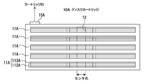
- FIG. 2 is a diagram illustrating a configuration of a disk cartridge, a drive unit, and a host device in the optical recording system of the first embodiment. It is sectional drawing which shows the structure of a multilayer optical disk. It is a top view of the multilayer optical disk of FIG. It is a figure which shows the structure of the disc drive in the optical recording system of 1st Embodiment. 3 is a flowchart relating to regular determination of a multilayer optical disc in the optical recording system of the first embodiment.
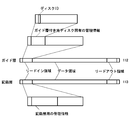
- FIG. 11 is a diagram showing physical formats of a guide layer and a recording layer in a multilayer optical disc according to Modification 1. It is a figure for demonstrating the disc cartridge in the 2nd Embodiment of this invention. It is a figure which shows the physical format of the guide layer and recording layer in the multilayer optical disk of 2nd Embodiment. It is a flowchart regarding the regular determination of the multilayer optical disk in 2nd Embodiment.
- FIG. 1 is a diagram showing an optical recording system according to an embodiment of the present invention. *
- FIG. 1 is a diagram showing the overall configuration of an optical recording system.
- the optical recording system 1 includes a disk cartridge 10, a disk transport mechanism 20, a drive unit 30, a RAID controller 40, and a host device 50. Details of each will be described below. *
- the disk cartridge 10 is a unit in which a plurality of multilayer optical disks 11 are individually detachably accommodated.
- the optical disk accommodated in the disk cartridge 10 is not necessarily a multilayer optical disk, and may be an optical disk having one or more recording layers.
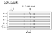
- FIG. 2 is a view showing a storage form of the disk cartridge 10 and a plurality of multilayer optical disks 11 therein.
- the accommodation form of the plurality of multilayer optical discs 11 in the disc cartridge 10 flat stacking, vertical alignment, and the like are assumed. In any case, it is preferable that a certain gap is provided between adjacent multilayer optical discs 11 so that the multilayer optical disc 11 can be smoothly inserted into and removed from the disc cartridge 10.
- the shape of the disk cartridge 10 is assumed to be, for example, a rectangular parallelepiped shape or a cylindrical shape from the viewpoint of handling by the user and the accommodation efficiency of the multilayer optical disk 11.
- a rectangular parallelepiped disk cartridge 10 in which a plurality of multilayer optical disks 11 are accommodated in a flat stack is used. *
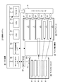
- FIG. 3 is a diagram showing the configuration of the disk cartridge 10, the drive unit 30, and the host device 50.
- At least one side surface of the disk cartridge 10 is provided with an opening 101 for loading and unloading the multilayer optical disk 11 and a door (not shown) for opening and closing the opening 101.
- the door is opened and closed in conjunction with the operation of loading / unloading the multilayer optical disk 11 from / to the disk cartridge 10 by the disk transport mechanism 20, and is closed at other times.
- the plurality of multilayer optical disks 11 accommodated in the disk cartridge 10 are taken out by the disk transport mechanism 20 and selectively transported (loaded) to the plurality of disk drives 31 in the drive unit 30.
- the disc cartridge 10 has, for example, an RF (Radio Frequency) tag that is a “recording unit” capable of recording disc IDs (disc identifiers) of a plurality of multilayer optical discs 11 accommodated therein. 15 is installed.
- the RF tag 15 includes an antenna unit and a circuit unit including a nonvolatile storage element and an arithmetic processing circuit for signal processing.
- the RF tag 15 may be any of a passive tag, an active tag, and a semi-active tag, and may employ either an electromagnetic induction method or a radio wave method as a radio wave transmission method. *
- the configuration of the disk cartridge 10 is not limited to that shown in FIG.
- Various modifications such as the shape of the disk cartridge 10, the number and position of the openings, the presence / absence of a door, and the accommodation form of a plurality of multilayer optical disks 11 are possible.
- the RF tag 15 is used as the recording unit, in the present embodiment, any recording medium that can record and read the disk ID of the multilayer optical disk 11 may be used.
- a magnetic recording medium, an optical recording medium, and a semiconductor memory It may be.
- the multilayer optical disc 11 accommodated in the disc cartridge 10 is a so-called guide layer separation type multilayer optical disc in which a guide layer and a recording layer are separated into separate layers. Assume the case. *
- FIG. 4 is a cross-sectional view showing the structure of the multilayer optical disk 11.
- the multilayer optical disc 11 has a guide layer 112 and one or more recording layers 113.
- the number of recording layers 113 is “4”.
- An intermediate layer 114 having optical transparency is interposed between the guide layer 112 and the recording layer 113 closest to the guide layer 112 and between the adjacent recording layers 113.
- These layers are the protective layer 115, the recording layer 113, the intermediate layer 114, the recording layer 113, the intermediate layer 114, the recording layer 113, the intermediate layer 114, the recording layer 113, the intermediate layer from the side on which the recording / reproducing light R1 and the guide light R2 from the optical pickup 32 are incident.
- the layer 114, the recording layer 113, the intermediate layer 114, and the guide layer 112 are stacked in this order. *
- a guide track 121 having a land / groove structure is spirally provided on the surface of the guide layer 112 facing the recording layer 113.
- On the side wall surface of the guide track 121 physical address information indicating position information over the entire circumference of the disk is recorded by wobble.
- the guide track 121 is formed with a track pitch (0.64 ⁇ m) corresponding to a red laser beam used for recording / reproduction of, for example, a DVD (Digital Versatile Disk).
- the average pitch between the land and the groove is 0.32 ⁇ m.
- the laser beam of the red laser beam is referred to as “guide light”. *
- the land portion and the groove portion are used as a guide track 121 having a spiral shape. Therefore, the pitch of the guide track 121 is 0.32 ⁇ m.
- a laser beam having a red wavelength (second wavelength) used for recording / reproducing of a DVD is used for tracking the guide track 121 of the guide layer 112
- the laser light having the second wavelength may be referred to as “guide light”.
- tracking control by, for example, a differential push-pull method (DPP: Differential Push-Pull) is performed in each of the land portion and the groove portion of the guide track 121.
- DPP Differential Push-Pull
- information recording on the recording layer 113 can be performed at a track pitch of 0.32 ⁇ m.
- the recording layer 113 is a layer on which information is recorded with a track pitch of 0.32 ⁇ m using a laser beam having a blue wavelength (first wavelength) used for recording and reproduction of a Blu-ray Disc (registered trademark), for example.
- the laser light having the first wavelength may be referred to as “recording / reproducing light” or “recording light”.
- the recording layer 113 is composed of, for example, a light absorption layer and a reflection layer.
- the light absorption layer organic dyes such as cyanine dyes and azo dyes, and inorganic materials such as Si, Cu, Sb, Te, and Ge are used.
- the recording layer 113 Since tracking control and physical address information at the time of recording and reproducing information on the recording layer 113 and acquisition of a recording clock such as a recording clock are performed using the wobble signal of the guide track 121 of the guide layer 112,
- the recording layer 113 does not require the guide track 121 having a land / groove structure. Therefore, the surface of the recording layer 113 may be flat.
- the disc conveying mechanism 20 takes out the target multilayer optical disk 11 from the disk cartridge 10 and loads it into the disk drive 31 in the drive unit 30, or conversely discharges the multilayer optical disk 11 ejected from the disk drive 31 into a disk This is a mechanism for returning to the cartridge 10.
- the disk transport mechanism 20 operates independently so that, for example, a plurality of multilayer optical disks 11 can be taken out simultaneously or sequentially from the disk cartridge 10 and can be separately loaded into the plurality of disk drives 31 in the drive unit 30.
- a plurality of possible transport mechanisms may be provided.
- the drive unit 30 is equipped with a plurality of disk drives 31 that are "disc recording / playback units". In the example of FIG. 5, five disk drives 31 are mounted. The number of multilayer optical disks 11 accommodated in the disk cartridge 10 and the number of disk drives 31 mounted in the drive unit 30 are not necessarily the same. *
- FIG. 6 is a diagram showing the configuration of the disk drive 31.
- the disk drive 31 includes an optical pickup 32.
- the optical pickup 32 includes a first optical system corresponding to the recording / reproducing light and a second optical system corresponding to the guide light. *
- the first optical system includes a first light source 33, a first collimator lens 34, a first polarizing beam splitter 35, a first relay lens 36, a second collimator lens 37, a combining prism 38, and a quarter wavelength.
- the plate 39, the objective lens 60, the first light receiving lens 61, the first light receiving unit 62, and the like are included.
- the synthesis prism 38, the quarter wavelength plate 39, and the objective lens 60 belong to both the first optical system and a second optical system described later. *
- the first light source 33 includes a laser diode that emits laser light having a first wavelength as recording / reproducing light R1.
- the recording / reproducing light R 1 emitted from the first light source 33 is converted into parallel light by the first collimator lens 34, and passes through the first polarization beam splitter 35, the first relay lens 36 and the second collimator lens 37.
- the light enters the combining prism 38.
- the synthesizing prism 38 receives recording / reproducing light R1 incident from the second collimator lens 37 and guide light R2 having a second wavelength incident from a third collimator lens belonging to the second optical system described later. Are combined so that their optical axes coincide with each other, and are incident on the objective lens 60 via the quarter-wave plate 39.
- the incident recording / reproducing light is collected by the objective lens 60 so as to be focused on the target recording layer 113 of the multilayer optical disc 11.
- the recording / reproducing light (returned light) reflected by the recording layer 113 is incident on the combining prism 38 via the objective lens 60 and the quarter wavelength plate 39, and is transmitted through the combining prism 38 in the incident direction.
- the first polarization beam splitter 35 reflects the return light of the first wavelength from the first relay lens 36 at an angle of about 90 degrees and passes through the first light receiving lens 61 to the first light receiving unit 62. Make it incident.
- the first light receiving unit 62 is composed of a light receiving element whose light receiving surface is divided into four in the disk radial direction and the tangential direction, and outputs a voltage signal of a level corresponding to the light receiving intensity for each of the divided light receiving surfaces. Is output to the equalizer 75 as a reproduction signal of recording data, and a voltage signal for each divided light receiving surface is output to a focus control unit (not shown). *
- the second optical system includes a second light source 63, a third collimator lens 64, a second polarizing beam splitter 65, a second relay lens 66, a fourth collimator lens 67, a combining prism 38, and a quarter wavelength.
- the second light source 63 emits guide light R2 having a second wavelength.
- the guide light R2 emitted from the second light source 63 is converted into parallel light by the third collimator lens 64, and is combined through the second polarization beam splitter 65, the second relay lens 66, and the fourth collimator lens 67.
- the light enters the prism 38.
- the guide light R2 incident on the combining prism 38 and the optical axis of the recording / reproducing light R1 having the first wavelength incident on the combining prism 38 from the second collimator lens 37 of the first optical system. Are made to coincide with each other and enter the objective lens 60 via the quarter-wave plate 39.
- the incident guide light R2 is condensed so as to be focused on the guide layer 112 of the multilayer optical disc 11. *
- the guide light R2 (return light) reflected by the guide layer 112 enters the synthesis prism 38 through the objective lens 60 and the quarter wavelength plate 39, and is reflected by the synthesis prism 38 at an angle of about 90 degrees.
- the second polarization beam splitter 65 reflects the return light of the guide light R2 from the second relay lens 66 at an angle of about 90 degrees, and passes through the second light receiving lens 68 to the second light receiving unit 69. Make it incident. *
- the second light receiving unit 69 is, for example, a light receiving element whose light receiving surface is divided into two in the disk radial direction orthogonal to the track, a light receiving element whose light receiving surface is divided into four in the disk radial direction and the tangential direction, or light receiving A main light-receiving element whose surface is divided into at least two parts and a combination of two sub-light-receiving elements divided into two parts are arranged on both sides of the main light-receiving element in the tangential direction.
- the second light receiving unit 69 selectively outputs a voltage signal having a level corresponding to the received light intensity of each divided light receiving surface to the tracking control unit 71 and the wobble signal processing unit 78. *
- the optical pickup 32 is provided with a tracking actuator 70 and a focusing actuator (not shown).
- the tracking actuator 70 moves the objective lens 60 in the disk radial direction based on the tracking drive signal from the tracking control unit 71.
- the focusing actuator moves the objective lens 60 in the optical axis direction by a focus drive signal from a focus control unit (not shown).
- the optical pickup 32 includes a first relay lens actuator that moves the first relay lens 36 in the optical axis direction so as to switch the recording layer 113 irradiated with the recording / reproducing light, and a first relay lens actuator.
- a second relay lens actuator for moving the second relay lens 66 in the optical axis direction is provided. The above is the description of the optical pickup 32.
- the disk drive 31 includes a data modulating unit 72, a first light source driving unit 73, a second light source driving unit 74, an equalizer 75, a data reproducing unit 76, a BCA processing unit 77, a tracking. It has a control unit 71, a wobble signal processing unit 78, a disk motor drive unit 79, a feed mechanism 80, a controller 82, a focus control unit (not shown), a relay lens control unit and the like. *
- the data modulator 72 modulates the recording data supplied from the controller 82 into a bit string signal suitable for forming a recording mark, and supplies the modulated signal to the first light source driver 73.
- the first light source drive unit 73 generates a drive pulse for driving the first light source 33 based on the modulation signal from the data modulation unit 72.
- the equalizer 75 binarizes the reproduction RF signal from the first light receiving unit 62 at a predetermined slice level after performing equalization processing such as PRML (PartialelResponse Maximum Likelihood), for example.
- PRML PartialelResponse Maximum Likelihood
- the data reproduction unit 76 demodulates data from the binary signal output from the equalizer 75, performs decoding processing such as error correction from the demodulated data, generates reproduction data, and supplies the reproduction data to the controller 82.
- the BCA processing unit 77 reproduces the disc ID (disc identifier) recorded in the BCA based on the reproduction RF signal from the first light receiving unit 62.
- the tracking control unit 71 generates a tracking error signal by, for example, the PP (push-pull) method or the DPP (differential push-pull) method based on the voltage signal of each divided light receiving surface of the second light receiving unit 69. Then, a tracking drive signal to be supplied to the tracking actuator 70 is generated based on the tracking error signal.
- PP push-pull
- DPP differential push-pull
- the wobble signal processing unit 78 reproduces the wobble signal based on the output of the second light receiving unit 69, demodulates the physical address information, and supplies it to the controller 82.
- the wobble signal processing unit 78 generates a reference recording clock from the wobble signal.
- the disk motor drive unit 79 supplies a drive signal to a disk motor 85 that rotates the multilayer optical disk 11 under the control of the disk motor control unit 81.
- the feed mechanism 80 is a mechanism for transporting the optical pickup 32 in the radial direction of the multilayer optical disc 11. *
- a focus control unit (not shown) supplies a focus drive signal to the focusing actuator based on a focus error signal from a focus error generation unit (not shown) to move the objective lens 60 in the optical axis direction.
- the controller 82 includes a central processing unit (CPU), a read only memory (ROM), a random access memory (RAM), and the like.
- the controller 82 controls the entire disk drive 31 based on a program loaded in the main memory area allocated to the RAM. *
- a plurality of the disk drives 31 described above are mounted on the drive unit 30 and can be controlled independently, and information can be recorded and reproduced on the loaded multilayer optical disk 11 simultaneously.
- RAID controller 40 A RAID (Redundant Arrays of Inexpensive Disks) controller 40 records data in multiple on one or more disk drives 31 in the drive unit 30 in response to a recording command from the host device 50, or performs striping. RAID control to record in a distributed manner is performed. *
- the controller 82 of each disk drive 31 to which a recording or reproduction instruction is given from the RAID controller 40 performs control for recording or reproducing data on the multilayer optical disk 11.
- the host device 50 is the highest-level device that controls the optical recording system 1.
- the host device 50 may be a personal computer.
- the host device 50 creates or prepares data for recording, and supplies a recording command for the data for recording to the RAID controller 40. Further, the host device 50 supplies a read command including a file name designated by a user or the like to the RAID controller 40, and acquires data of the corresponding file name from the RAID controller 40 as a response.
- the host device 50 includes a CPU 51, a memory 52, a drive I / F 53, a disk transport mechanism I / F 54, an RF read / writer I / F 55, and a system bus 56.
- the CPU 51 (control unit) performs arithmetic processing for executing a program stored in the memory 52 and controls exchange of information with each unit through the system bus 56.
- the memory 52 is a main memory that stores programs to be executed by the CPU 51, operation results, and the like.
- the drive I / F 53 is an interface for communicating with the plurality of disk drives 31 through the RAID controller 40. *
- the disk transport mechanism I / F 54 is an interface for communicating with the disk transport mechanism 20. *
- the RF reader / writer I / F 55 is an interface for communicating with the RF tag reader / writer 57.
- the RF tag reader / writer 57 is used as an access unit that can perform recording and reading with respect to the RF tag 15 that is a recording unit provided with the disk cartridge 10.
- the access unit capable of performing both recording and reading with respect to the RF tag 15 as a recording unit is employed, but the present invention is not limited to this.
- the controller 82 of the disk drive 31 controls the feed mechanism 80 so that the optical pickup 32 is moved to a position corresponding to the innermost circumference of the area where data is not recorded in the recording area of the recording layer 113 of the multilayer optical disk 11. Then, the disk motor drive unit 79 is controlled to rotate the disk 11 at an appropriate speed in the CLV method or the CAV method.
- the controller 82 positions the first relay lens 36 of the optical pickup 32 in the optical axis direction so that the recording light from the objective lens 60 of the optical pickup 32 is focused on the target recording layer 113 of the multilayer optical disc 11. And the position of the second relay lens 66 of the optical pickup 32 in the optical axis direction is controlled so that the guide light from the objective lens 60 of the optical pickup 32 is focused on the guide layer 112 of the multilayer optical disc 11.
- the controller 82 of the disk drive 31 supplies the recording data transferred from the host device 50 through the RAID controller 40 to the data modulator 72.
- the data modulation unit 72 generates a recording signal by performing modulation of recording data, adding an error correction code, and the like, and supplies the recording signal to the first light source driving unit 73.
- the first light source driving unit 73 generates a driving pulse for the first light source 33 based on the recording signal and supplies it to the first light source 33.
- the controller 82 outputs a control signal to the second light source driving unit 74 so as to drive the second light source 63.
- recording of data on the recording layer 113 by the recording light from the optical pickup 32 is started. That is, data recording in the CLV method or CAV method is started from the inner periphery to the outer periphery with respect to the target recording layer 113 of the multilayer optical disc 11.
- the CPU 51 of the host device 50 determines whether the multilayer optical disc 11 loaded in each disk drive 31 of the drive unit 30 is in accordance with a program stored in the memory 52. The process is performed as follows. *
- the CPU 51 of the host device 50 assigns the disk IDs of the plurality of multilayer optical disks 11 loaded from the disk cartridge 10 to the respective disk drives 31 to the RF tag 15 provided in the disk cartridge 10. Recorded as “information for associating a plurality of optical disks and disk cartridges”. Thereafter, when the disk cartridge 10 having a plurality of disk IDs already recorded on the RF tag 15 is set in the optical recording system 1, the CPU 51 of the host device 50 reads the plurality of disk IDs read from the RF tag 15 and the respective disk IDs. The disk ID read from the multilayer optical disk 11 loaded in the disk drive 31 is collated. Thereby, it is possible to determine whether or not the multilayer optical disk 11 loaded in each disk drive 31 is a regular disk associated with the disk cartridge 10. *
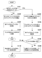
- FIG. 7 is a flowchart relating to regular determination of a multilayer optical disc in the optical recording system 1 of the first embodiment. *
- the CPU 51 of the host device 50 causes the RF tag reader / writer 57 to search for the RF tag 15 through the RF reader / writer I / F 55.
- the disc cartridge 10 is set at a predetermined position in the optical recording system 1
- non-contact communication between the RF tag reader / writer 57 and the RF tag 15 provided in the disc cartridge 10 is started.
- the CPU 51 of the host device 50 knows that non-contact communication with the RF tag 15 has started (START), it controls the RF tag reader / writer 57 to determine whether or not the disk ID is recorded on the RF tag 15. Confirm (step S101). *
- step S101 the CPU 51 controls the disk transport mechanism 20 through the disk transport mechanism I / F 54 to store the disk ID in the disk cartridge 10.
- Each multilayer optical disk 11 is transported to each disk drive 31 in the drive unit 30 (step S102).
- the CPU 51 of the host device 50 instructs each disk drive 31 in the drive unit 30 to read the disk ID recorded in the BCA through the drive I / F 53. To do. *
- the CPU 51 of the host device 50 acquires each disk ID read by each disk drive 31 in the drive unit 30 through the drive I / F 53 as “a set of disk IDs corresponding to the disk cartridge 10” (step S103).
- a write command including the set of the disk ID is output to the RF tag read / writer 57 through the RF read / writer I / F 55.
- the RF tag reader / writer 57 communicates with the RF tag 15 provided in the disk cartridge 10 so as to record a set of disk IDs included in the write command (step S104).
- the disk ID corresponding to the disk cartridge 10 is stored in the nonvolatile storage element of the RF tag 15. A set of is recorded.
- step S101 in FIG. 7 If it is determined in step S101 in FIG. 7 that the disk ID is recorded in the RF tag 15 (YES in step S101), a read command for setting the disk ID Is output to the RF tag reader / writer 57 through the RF reader / writer I / F 55.
- the RF tag read / writer 57 reads a set of disk IDs from the RF tag 15 according to this read command, and responds to the CPU 51 through the RF read / writer I / F 55.
- the CPU 51 of the host device 50 obtains a set of disk IDs recorded in the RF tag 15 (step S105), it stores it in the memory 52. *
- the CPU 51 of the host device 50 transports each multilayer optical disk 11 in the disk cartridge 10 to each disk drive 31 in the drive unit 30 (step S106), and then each disk in the drive unit 30 through the drive I / F 53.
- the drive 31 is instructed to read the disc ID recorded in the BCA.
- the CPU 51 of the host device 50 acquires each disk ID read by each disk drive 31 in the drive unit 30 through the drive I / F 53 (step S107), the acquired individual disk ID is stored in the memory 52. It collates with the set of ID (step S108). If each disk ID obtained from the disk drive 31 matches any one of the set of disk IDs stored in the memory 52, the CPU 51 of the host device 50 loads each disk drive 31 in the drive unit 30. It is determined that the multi-layer optical disk 11 is a regular disk set associated with the disk cartridge 10, and processing for recording user data by each disk drive 31 in the drive unit 30 is started (step S109). . *
- the CPU 51 of the host device 50 determines that the non-regular multilayer optical disk 11 that is not linked to the disk cartridge 10 is used.
- a display (not shown) connected to the host device 50, which determines that the disk drive 31 is loaded and the disk ID of the non-regular multilayer optical disk 11 and the device ID of the disk drive 31 loaded with the multilayer optical disk 11 Error processing such as displaying on the screen is performed (step S110). *
- the user of the host device 50 can input an instruction to eject the irregular multilayer optical disk 11 from the disk drive 31 of the device ID, for example, according to the error process.
- the CPU 51 of the host device 50 sends a command to the corresponding disk drive 31 through the drive I / F 53 so as to eject the irregular multilayer optical disk 11 from the corresponding disk drive 31, and from the disk drive 31.
- a command is sent to the disk transport mechanism 20 through the disk transport mechanism I / F 54 so that the discharged irregular multilayer optical disk 11 is returned to the disk cartridge 10.
- the irregular multilayer optical disc 11 is returned to the disc cartridge 10.
- the user may input an instruction to eject the multilayer optical disk 11 from all the disk drives 31 in the drive unit 30.
- the CPU 51 of the host device 50 sends a command to all the disk drives 31 through the drive I / F 53 so as to eject the multi-layer optical disk 11 from all the disk drives 31, and is ejected from all the disk drives 31.
- a command is sent to the disk transport mechanism 20 through the disk transport mechanism I / F 54 so that the multilayer optical disk 11 is returned to the disk cartridge 10.
- all the multilayer optical disks 11 including the non-regular multilayer optical disk 11 are returned to the disk cartridge 10.
- the user can perform, for example, an operation of compensating the missing multilayer optical disk 11 in the disk cartridge 10.
- the disk cartridge 10 and a plurality of multilayer optical disks 11 that are normally accommodated in the disk cartridge 10 can be logically linked using the disk ID. Therefore, the host device 50 can determine and notify the user that some of the multilayer optical disks 11 are replaced or missing in the disk cartridge 10. Since the user is notified before the access error occurs, the user's evaluation on the reliability of the system is not greatly impaired.
- the disk ID of the multilayer optical disk 11 is used as information for associating the disk cartridge 10 and the multilayer optical disk 11, so that the recording unit such as the RF tag 15 of the disk cartridge 10 can be used. It is possible to link each other only by recording the disk ID, and it is not necessary to define new information for linking.
- the disc ID of the multilayer optical disc 11 as information for associating the disc cartridge 10 and the multilayer optical disc 11, the disc ID of the multilayer optical disc 11 missing in the disc cartridge 10 can be determined. The efficiency of the work of restoring the set of the plurality of multilayer optical disks 11 accommodated in the disk cartridge 10 can be improved.
- the disk ID read from the multilayer optical disk is recorded on the RF tag 15 of the disk cartridge 10 of the first embodiment.
- a unique ID hereinafter referred to as “cartridge ID”
- the CPU 51 of the host device 50 records the cartridge ID read from the RF tag 15A in the lead-in area (see FIG. 10) of the recording layer 113A of the multilayer optical disk 11A loaded in the disk drive 31.
- the cartridge ID is used as information for associating a plurality of optical disks and disk cartridges.
- FIG. 10 is a diagram showing the physical format of the guide layer 112A and the recording layer 113A in the multilayer optical disc 11A of the second embodiment.
- the guide layer 112A and the recording layer 113A are divided in common to each layer into a lead-in area, a data area, and a lead-out area from the inner peripheral side depending on the position in the radial direction. *
- management information unique to the multilayer optical disc 11A is recorded in advance by wobble modulation of a guide track or a pit string.
- Management information unique to the multilayer optical disc 11A includes, for example, disc ID, number of recording layers, recording method, recording linear velocity, recommended data such as laser power and laser driving pulse waveform during recording / reproducing, address of user data area, Includes the address of the OPC area.
- the lead-in area of the recording layer 113 is an area where management information used for recording / reproducing on the recording layer 113 is recorded by a pit string.
- the management information used for recording / reproduction to / from the recording layer 113 is obtained by, for example, defect management information indicating the correspondence between the start address and end address of the recorded area, the address of the defect area and the address of the replacement area, and OPC processing.
- OPC data such as the optimum recording laser power value.
- the lead-in area of the recording layer 113 the above cartridge ID and the like are further recorded. *
- the recording unit is not limited to the RF tag 15A capable of recording and reading information, and may be a read-only RF tag.
- the recording unit related to the second embodiment may be anything as long as the cartridge ID is recorded in advance and can be read by the access unit.
- a bar code, a QR (registered trademark) code may be used. It may be a printed matter of recorded information such as Therefore, in this case, the access unit only needs to be readable from the recording unit.
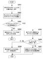
- FIG. 11 is a flowchart relating to regular determination of a multilayer optical disc in the optical recording system of the second embodiment. *
- the CPU 51 of the host device 50 causes the RF tag reader / writer 57 to search for the RF tag 15 through the RF reader / writer I / F 55.
- the disk cartridge 10A is set at a predetermined position in the optical recording system 1
- non-contact communication between the RF tag reader / writer 57 and the RF tag 15A provided in the disk cartridge 10A is started.
- the CPU 51 of the host device 50 knows that non-contact communication with the RF tag 15A has started (START), it controls the RF tag reader / writer 57 to read the cartridge ID recorded on the RF tag 15A. And stored in the memory 52 (step S201).
- the CPU 51 of the host device 50 controls the disk transport mechanism 20 through the disk transport mechanism I / F 54 to transport each multilayer optical disk 11A in the disk cartridge 10A to each disk drive 31 in the drive unit 30 (step). S202). *
- the CPU 51 of the host device 50 sends the cartridge ID from the lead-in area of the recording layer 113A to each disk drive 31 in the drive unit 30 through the drive I / F 53. Send instructions to attempt to read *
- the cartridge ID is recorded in the lead-in area of the recording layer 113A. Absent. Therefore, in this case, the failure of reading the cartridge ID is notified from all the disk drives 31 loaded with the multilayer optical disk 11A to the CPU 51 of the host device 50 (NO in step S203). Upon receiving these notifications, the CPU 51 of the host device 50 reads the cartridge ID stored in the memory 52 and sends the disk drive 31 in the drive unit 30 to the lead-in area via the drive I / F 53. An instruction is given to record the cartridge ID.
- Each disk drive 31 in the drive unit 30 records the cartridge ID in the lead-in area of the multilayer optical disk 11A loaded in accordance with this instruction (step S204).
- each disk drive 31 reads the cartridge ID, and the host device 50 Transfer to the CPU 51.
- the CPU 51 of the host device 50 acquires the cartridge ID from each disk drive 31 (step S205)
- the acquired individual cartridge ID is collated with the cartridge ID stored in the memory 52 (step S206).
- each disk drive in the drive unit 30 causes each disk drive in the drive unit 30 to be It is determined that each multilayer optical disk 11A loaded in the disk 31 is a regular disk set associated with the disk cartridge 10A, and processing for recording user data by each disk drive 31 in the drive unit 30 is started. (Step S207). *
- the CPU 51 of the host device 50 determines that the multilayer optical disk 11A loaded in the disk drive 31 is a disk cartridge. It is determined that the non-regular multilayer optical disc 11A is not linked to 10A, and the disc ID of the non-regular multilayer optical disc 11A and the device ID of the disc drive 31 in which the non-regular multilayer optical disc 11A is loaded are determined. Error processing such as displaying on a display (not shown) connected to the host device 50 is performed (step S208). *
- the disk cartridge 10A and a plurality of multilayer optical disks 11A that are properly accommodated in the disk cartridge 10A can be logically linked using the cartridge ID. Therefore, the host device 50 can determine and notify the user that some of the multilayer optical disks 11A have been replaced or missing in the disk cartridge 10A. Since the user is notified before the access error occurs, the user's evaluation on the reliability of the system is not greatly impaired. *
Landscapes
- Optical Recording Or Reproduction (AREA)
- Automatic Tape Cassette Changers (AREA)
- Automatic Disk Changers (AREA)
Description
本発明は、それぞれ1以上の記録層を有する複数の光ディスクを着脱自在なディスクカートリッジから取り出された複数の光ディスクに記録を行うことが可能な光記録システムと、そのディスクカートリッジに関する。
DVD(Digital Versatile Disk)、ブルーレイディスク(登録商標)などの光ディスクの大容量化を目的として、記録層を多層化することが行われる。記録層の多層化に伴い、記録層へのデータの記録または再生時のトラックキング制御を、記録層とは別の層に設けられたガイドトラックを用いて行う方式も知られている。
例えば、溝構造によるガイドトラックが設けられたガイドトラック層に390nm~420nmの波長(青色)の光を使用してトラッキング制御を行うとともに、複数の記録層の中の一つの記録層に650nm~680nmの波長(赤色)の光を使用して記録を行う光ドライブ装置などがある(例えば、特許文献1等)。
また、光ディスクには、この光ディスクを光記録システムが識別することが可能なようにディスク毎にユニークなIDが記録される場合がある。例えば、特許文献2においては、光ディスクのBCA(Burst Cutting Area)に記録されているディスクIDが光ピックアップユニットにより読み出され、記録再生装置内の不揮発性メモリに、当該光ディスクに対して求められたフォーカスサーボ用の制御値、トラッキングサーボ用の制御値、レーザ制御値などと紐付けて記憶される。次回、同じディスクIDの光ディスクが装填された場合、記録再生装置は、不揮発性メモリから、そのディスクIDに紐付けられて記憶された上記制御値を読み込み、これらの制御値を用いてフォーカスサーボ、トラッキングサーボ、レーザ光の強度などの調整を行う。これにより、光ディスクが装填される毎に上記制御値を求める必要が無くなり、光ディスクが装填されてから実際にデータの記録再生が開始されるまでの起動時間を短縮することができる。また、この特許文献2には、光ディスクを収容したカートリッジに、当該光ディスクのディスクIDをバーコード、QR(登録商標)コードなどで印刷することなども記載されている。
近年、光ディスクに対するデータ転送速度のさらなる向上を図るため、複数の多層光ディスクに対して複数のディスクドライブを用いて並行して記録/再生を行うことが可能な光記録システムが検討されている。このような光記録システムでは、複数の多層光ディスクをディスクカートリッジに一体に収容した形態でシステムに導入されることが想定されている。光記録システム内では、ディスクカートリッジから、それぞれの多層光ディスクが別々のディスクドライブに装填されるように自動搬送される。
このような光記録システムにおいて、ディスクカートリッジ単位の複数の多層光ディスクは、例えばRAID(Redundant Arrays of Inexpensive Disks)の構築などを目的に1つの連続した記録空間として用いられる。しかしながら、ディスクカートリッジに対して多層光ディスクは個別に出し入れされることは不可避であるため、例えば、光記録システム内でのメカ的なトラブルやシステム外での人的なミスなどによって、多層光ディスクの入れ替わりや欠落などが発生する可能性がある。
ディスクカートリッジにおいて多層光ディスクの入れ替わりや欠落などがあると、ディスクカートリッジ単位の複数の多層光ディスクのアクセスに対してエラーが発生する。このアクセスエラーに対してユーザは、その原因をディスクカートリッジにおける多層光ディスクの入れ替わりや欠落などと結び付けることは困難である。故に、ユーザは問題の解決に時間を消費し、結果的にシステムの信頼性に対するユーザによる評価を大きく損ねる可能性があった。
以上のような事情に鑑み、本発明の目的は、ディスクカートリッジとこれに収容される複数の光ディスクとの論理的な紐付けを実現し、ユーザの利便性を向上させることのできる光記録システムおよびディスクカートリッジを提供することにある。
上記目的を達成するため、本発明の一形態に係る光記録システムは、複数の光ディスクの着脱が可能とされ、記録部が設けられたディスクカートリッジであって、前記ディスクカートリッジの前記光ディスクおよび前記記録部のいずれか一方に前記複数の光ディスクと前記ディスクカートリッジとを紐付けるための情報が予め記録されており、前記ディスクカートリッジから取り出された前記複数の光ディスクに対して記録および読み出しが可能なディスク記録再生部と、前記ディスクカートリッジの前記記録部に対して記録および読み出しの少なくとも一方が可能なアクセス部と、前記ディスク記録再生部および前記アクセス部のいずれか一方により前記情報を読み出させ、他方により当該情報を記録させる制御部と、を具備する。
この光記録システムでは、このような構成を有することによって、ディスクカートリッジとこれに収容された複数の光ディスクに明示的な紐付けの情報を共有させることができる。
前記制御部は、前記光ディスクと前記記録部にそれぞれ前記情報が記録されている場合、両情報を照合して、前記複数の光ディスクそれぞれが前記ディスクカートリッジに対して紐付けられたものであるかどうかを判定するものであってよい。
これにより、ディスクカートリッジとこのディスクカートリッジからディスク記録再生部に供給された光ディスクとの紐付けの関係を検証することができる。
光ディスクと前記ディスクカートリッジとを紐付けるための情報としては、前記光ディスクに予め記録されているディスク識別子および前記記録部に予め記録されているカートリッジ識別子のいずれか一方を用いることができる。
本発明の他の形態に係る光記録システムは、複数の光ディスクの着脱が可能とされ、記録部が設けられたディスクカートリッジであって、前記ディスクカートリッジの前記光ディスクに前記複数の光ディスクと前記ディスクカートリッジとを紐付けるための情報が予め記録されており、前記ディスクカートリッジから取り出された前記複数の光ディスクに対して記録および読み出しが可能なディスク記録再生部と、前記ディスクカートリッジの前記記録部に対して記録および読み出しが可能なアクセス部と、前記ディスク記録再生部により前記光ディスクからそれぞれ前記情報を読み出させ、前記アクセス部により前記情報を前記記録部に記録させる制御部と、を具備する。
この光記録システムでは、光ディスクとディスクカートリッジとを紐付けるための情報として、光ディスクに予め記録されているディスク識別子を用いることができる。
この光記録システムでは、前記光ディスクと前記記録部にそれぞれ前記情報が記録されている場合、両情報を照合して、前記複数の光ディスクそれぞれが前記ディスクカートリッジに対して紐付けられたものであるかどうかを判定することができる。
本発明の他の形態に係る光記録システムは、複数の光ディスクの着脱が可能とされ、記録部が設けられたディスクカートリッジであって、前記ディスクカートリッジの前記記録部に前記複数の光ディスクと前記ディスクカートリッジとを紐付けるための情報が予め記録されており、前記ディスクカートリッジから取り出された前記複数の光ディスクに対して記録および読み出しが可能なディスク記録再生部と、前記ディスクカートリッジの前記記録部に対して読み出しが可能なアクセス部と、前記アクセス部により前記記録部から前記情報を読み出させ、前記ディスク記録再生部により前記光ディスクに記録させる制御部と、を具備する。
この光記録システムでは、光ディスクとディスクカートリッジとを紐付けるための情報として、記録部に予め記録されているカートリッジ識別子を用いることができる。
本発明の別の側面に係るディスクカートリッジは、複数の光ディスクの着脱が可能とされ、記録部が設けられたディスクカートリッジであって、前記複数の光ディスクおよび前記記録部のいずれか一方に当該光ディスクと前記ディスクカートリッジとを紐付けるための情報が予め記録されたものである。
以上のように、本発明によれば、ディスクカートリッジとこれに収容される複数の光ディスクとの論理的な紐付けを実現して、ユーザの利便性を向上させることができる。
以下、図面を参照しながら、本発明の実施形態を説明する。 図1は、本発明の一実施形態に係る光記録システムを示す図である。
図1は光記録システムの全体の構成を示す図である。 この光記録システム1は、ディスクカートリッジ10と、ディスク搬送機構20と、ドライブユニット30と、RAIDコントローラ40と、ホスト装置50とを備える。以下、それぞれの詳細について説明する。
[ディスクカートリッジ10] ディスクカートリッジ10は、複数の多層光ディスク11が個別に着脱自在に収容されるユニットである。なお、本発明においては、ディスクカートリッジ10に収容される光ディスクは必ずしも多層光ディスクである必要はなく、1以上の記録層を有する光ディスクであればよい。
図2はディスクカートリッジ10とこの中の複数の多層光ディスク11の収容形態を示す図である。ディスクカートリッジ10内での複数の多層光ディスク11の収容形態としては平積み、縦並びなどが想定される。いずれの場合も、ディスクカートリッジ10に対して多層光ディスク11の出し入れが円滑に行われるように、隣り合う多層光ディスク11間には一定の隙間が設けられることが好ましい。ディスクカートリッジ10の形状は、ユーザによるハンドリング性、多層光ディスク11の収容効率などの点から、例えば直方体形状、円筒形状などが想定される。図1の例では、複数の多層光ディスク11を平積みで収容した直方体形状のディスクカートリッジ10が用いられる。
図3は、ディスクカートリッジ10、ドライブユニット30およびホスト装置50の構成を示す図である。ディスクカートリッジ10の少なくとも一つの側面には多層光ディスク11の出し入れのための開口部101と、この開口部101を開閉する扉(図示せず)とが設けられている。扉はディスク搬送機構20によるディスクカートリッジ10からの多層光デ
ィスク11の出し入れの動作と連動して開閉され、その他のときは閉状態とされる。ディスクカートリッジ10に収容された複数の多層光ディスク11は、ディスク搬送機構20によって取り出され、ドライブユニット30内の複数のディスクドライブ31に選択的に搬送(装填)される。
ィスク11の出し入れの動作と連動して開閉され、その他のときは閉状態とされる。ディスクカートリッジ10に収容された複数の多層光ディスク11は、ディスク搬送機構20によって取り出され、ドライブユニット30内の複数のディスクドライブ31に選択的に搬送(装填)される。
図1ないし図3に示すように、ディスクカートリッジ10には、これに収容される複数の多層光ディスク11のディスクID(ディスク識別子)を記録可能な「記録部」である例えばRF(Radio Frequency)タグ15が装着されている。RFタグ15は、具体的には、アンテナ部と、不揮発性の記憶素子および信号処理などのための演算処理回路などを備える回路部とを有する。なお、RFタグ15は、パッシブタグ、アクティブタグ、セミアクティブタグのいずれであってもよく、電波の伝達方式として、電磁誘導方式、電波方式のいずれを採用したものであってもよい。
なお、本発明において、ディスクカートリッジ10の構成は図2のものに限定されない。ディスクカートリッジ10の形状、開口部の数や位置、扉の有無、複数の多層光ディスク11の収容形態など、様々な変形が可能である。 また、記録部としてRFタグ15を用いることを想定したが、本実施形態では多層光ディスク11のディスクIDを記録して読み出せるものであればよく、例えば、磁気記録媒体、光記録媒体、半導体メモリなどであってもよい。
[多層光ディスク11] 本実施形態においては、ディスクカートリッジ10に収容される多層光ディスク11は、ガイド層と記録層とが別々の層に分離して形成された、いわゆるガイド層分離型多層光ディスクである場合を想定している。
図4は多層光ディスク11の構造を示す断面図である。 多層光ディスク11は、ガイド層112と1以上の記録層113とを有する。同図の多層光ディスク11の例では記録層113の層数は"4"である。ガイド層112とこれに最も近い記録層113との間、隣り合う記録層113の間との間には光透過性を有する中間層114がそれぞれ介層されている。これらの層は、光ピックアップ32からの記録再生光R1およびガイド光R2が入射される側から、保護層115、記録層113、中間層114、記録層113、中間層114、記録層113、中間層114、記録層113、中間層114、ガイド層112の順に積層配置される。
ガイド層112において記録層113に対向する側の面には、ランド・グルーブ構造によるガイドトラック121が螺旋状に設けられている。ガイドトラック121の側壁面にはウォブルによって、ディスク全周にわたる位置情報を示す物理アドレス情報が記録されている。ガイドトラック121は、例えばDVD(Digital Versatile Disk)の記録再生に用いられる赤色レーザ光に対応するトラックピッチ(0.64μm)で形成される。ランドとグルーブ間のピッチの平均は0.32μmである。以後、赤色レーザ光のレーザ光を「ガイド光」と呼ぶ。
本実施形態では、ランド・グルーブ記録を想定しているため、ランド部とグルーブ部が螺旋状に連続するガイドトラック121として用いられる。したがって、ガイドトラック121のピッチは0.32μmとなる。
ガイド層112のガイドトラック121のトラッキングには、DVDの記録再生に用いられる赤色波長(第2の波長)のレーザ光が用いられる。以降において第2の波長のレーザ光を「ガイド光」と呼ぶ場合がある。
本実施形態の光記録システム1では、ガイドトラック121のランド部とグルーブ部のそれぞれにおいて、例えば、差動プッシュプル法(DPP:Differential Push-Pull)などによるトラッキング制御が行われる。ガイドトラック121のランド部とグルーブ部のそれぞれにおいてトラッキング制御が行われることで、記録層113に対する情報の記録は0.32μmのトラックピッチで行うことが可能である。 以上がガイド層112の説明である。
記録層113は、例えばブルーレイディスク(登録商標)の記録再生に用いられる青色波長(第1の波長)のレーザ光を用いて0.32μmのトラックピッチで情報の記録が行われる層である。以後、第1の波長のレーザ光を「記録再生光」または「記録光」と呼ぶ場合がある。
記録層113は、例えば光吸収層と反射層等とにより構成される。光吸収層としてはシアニン系色素やアゾ系色素等の有機色素や、Si、Cu、Sb、Te、Ge等の無機材料が用いられる。記録光が多層光ディスク11における目的の記録層113に照射されると、その記録光が照射された領域の反射率が変化し、反射率が変化した領域がピットとして形成されることで、記録層113に情報が記録される。
なお、記録層113への情報の記録時および再生時のトラッキング制御および物理アドレス情報、ならびに記録クロックなどの記録クロックの取得は、ガイド層112のガイドトラック121のウォブル信号を用いて行われるため、記録層113にはランド・グルーブ構造によるガイドトラック121は不要である。したがって、記録層113の表面は平坦でよい。
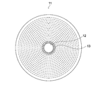
図5は多層光ディスク11の平面図である。 同図に示すように、多層光ディスク11のセンタ孔12の周囲近傍には、当該多層光ディスク11のディスクIDが記録されたBCA(Burst Cutting Area)13が設けられている。
[ディスク搬送機構20] ディスク搬送機構20は、ディスクカートリッジ10から目的の多層光ディスク11を取り出してドライブユニット30内のディスクドライブ31に装填したり、逆にディスクドライブ31から排出された多層光ディスク11をディスクカートリッジ10に戻したりするための機構である。
ディスク搬送機構20は、例えば、ディスクカートリッジ10から同時あるいは順番連続して複数の多層光ディスク11を取り出し、ドライブユニット30内の複数のディスクドライブ31に別々に装填することができるように、独立して動作可能な複数の搬送機構を備えたものであってもよい。
[ドライブユニット30] ドライブユニット30には「ディスク記録再生部」である複数のディスクドライブ31が搭載される。同図の例では、5機のディスクドライブ31が搭載される。ディスクカートリッジ10に収容される多層光ディスク11の数とドライブユニット30内に搭載されるディスクドライブ31の数は必ずしも同じとする必要はない。
(ディスクドライブ31の構成) 図6はディスクドライブ31の構成を示す図である。ディスクドライブ31は、光ピックアップ32を備える。この光ピックアップ32は、記録再生光に対応する第1の光学系と、ガイド光に対応する第2の光学系とを備える。
第1の光学系は、第1の光源33、第1のコリメータレンズ34、第1の偏光ビームスプリッタ35、第1のリレーレンズ36、第2のコリメータレンズ37、合成プリズム38、1/4波長板39、対物レンズ60、第1の受光レンズ61および第1の受光部62などで構成される。ここで、合成プリズム38、1/4波長板39、対物レンズ60は、当該第1の光学系と後述する第2の光学系の両方に属する。
第1の光源33は第1の波長のレーザ光を記録再生光R1として出射するレーザダイオードを備える。第1の光源33から出射された記録再生光R1は第1のコリメータレンズ34によって平行光とされ、第1の偏光ビームスプリッタ35、第1のリレーレンズ36及び第2のコリメータレンズ37を介して合成プリズム38に入射する。合成プリズム38は、第2のコリメータレンズ37から入射される記録再生光R1と、後述する第2の光学系に属する第3のコリメータレンズから入射される第2の波長のガイド光R2とを互いの光軸が一致するように合成し、1/4波長板39を介して対物レンズ60に入射させる。対物レンズ60にて、入射された記録再生光は、多層光ディスク11の目的の記録層113に合焦させるように集光される。
記録層113によって反射された記録再生光(戻り光)は、対物レンズ60、1/4波長板39を介して合成プリズム38に入射し、合成プリズム38を入射方向のまま透過して、第2のコリメータレンズ37及び第1のリレーレンズ36を介して第1の偏光ビームスプリッタ35に戻る。第1の偏光ビームスプリッタ35は、第1のリレーレンズ36からの第1の波長の戻り光を約90度の角度で反射して第1の受光レンズ61を介して第1の受光部62に入射させる。
第1の受光部62は、受光面がディスク半径方向とタンジェンシャル方向に4分割された受光素子で構成され、分割された受光面毎に受光強度に応じたレベルの電圧信号を出力し、これらを加算した信号を記録データの再生信号として等化器75に出力し、分割された受光面毎の電圧信号を図示しないフォーカス制御部などに出力する。
第2の光学系は、第2の光源63、第3のコリメータレンズ64、第2の偏光ビームスプリッタ65、第2のリレーレンズ66、第4のコリメータレンズ67、合成プリズム38、1/4波長板39、対物レンズ60、第2の受光レンズ68および第2の受光部69などで構成される。
第2の光源63は、第2の波長のガイド光R2を出射する。第2の光源63から出射されたガイド光R2は第3のコリメータレンズ64によって平行光とされ、第2の偏光ビームスプリッタ65、第2のリレーレンズ66及び第4のコリメータレンズ67を介して合成プリズム38に入射する。合成プリズム38に入射されたガイド光R2は、前述したように、合成プリズム38にて第1の光学系の第2のコリメータレンズ37から入射される第1の波長の記録再生光R1と光軸が一致するように合成され、1/4波長板39を介して対物レンズ60に入射される。対物レンズ60にて、入射されたガイド光R2は多層光ディスク11のガイド層112に合焦させるように集光される。
ガイド層112によって反射されたガイド光R2(戻り光)は、対物レンズ60、1/4波長板39を介して合成プリズム38に入射し、合成プリズム38にて約90度の角度で反射され、第4のコリメータレンズ67及び第2のリレーレンズ66を介して第2の偏光ビームスプリッタ65に戻る。第2の偏光ビームスプリッタ65は、第2のリレーレンズ66からのガイド光R2の戻り光を、約90度の角度で反射して第2の受光レンズ68を介して第2の受光部69に入射させる。
第2の受光部69は、例えば、受光面がトラックと直交するディスク半径方向に2分割された受光素子、あるいは、受光面がディスク半径方向とタンジェンシャル方向に4分割された受光素子、あるいは受光面が少なくとも2分割されたメインの受光素子とこのメインの受光素子のタンジェンシャル方向の両側にそれぞれ配置され、2分割された2つのサブの受光素子との組み合わせ、などで構成される。第2の受光部69は、分割された各受光面の受光強度に応じたレベルの電圧信号を選択的にトラッキング制御部71およびウォブル信号処理部78などに出力する。
また、光ピックアップ32には、トラッキングアクチュエータ70とフォーカシングアクチュエータ(図示せず)が設けられている。トラッキングアクチュエータ70はトラッキング制御部71からのトラッキング駆動信号をもとに対物レンズ60をディスク半径方向に移動させる。フォーカシングアクチュエータは、図示しないフォーカス制御部からのフォーカス駆動信号により対物レンズ60を光軸方向に移動させる。
さらに、図示は省略したが、光ピックアップ32には、記録再生光が照射される記録層113を切り替えるように第1のリレーレンズ36を光軸方向に移動させる第1のリレーレンズアクチュエータと、第2のリレーレンズ66を光軸方向に移動させる第2のリレ
ーレンズアクチュエータが設けられている。 以上が、光ピックアップ32の説明である。
ーレンズアクチュエータが設けられている。 以上が、光ピックアップ32の説明である。
ディスクドライブ31は、上記の光ピックアップ32のほか、データ変調部72、第1の光源駆動部73、第2の光源駆動部74、等化器75、データ再生部76、BCA処理部77、トラッキング制御部71、ウォブル信号処理部78、ディスクモータ駆動部79、フィード機構80、コントローラ82、さらには図示しないフォーカス制御部、リレーレンズ制御部などを有する。
データ変調部72は、コントローラ82より供給された記録用のデータを記録マークの形成に適したビット列信号に変調し、変調信号を第1の光源駆動部73に供給する。
第1の光源駆動部73は、データ変調部72からの変調信号をもとに第1の光源33を駆動するための駆動パルスを生成する。
等化器75は、第1の受光部62からの再生RF信号に対して、例えばPRML(Partial Response Maximum Likelihood)などの等化処理を行ってから所定のスライスレベルで二値化する。
データ再生部76は、等化器75より出力された二値信号からデータを復調し、復調されたデータから誤り訂正などの復号処理を行って再生データを生成し、コントローラ82に供給する。
BCA処理部77は、第1の受光部62からの再生RF信号をもとにBCAに記録されたディスクID(ディスク識別子)を再生する。
トラッキング制御部71は、第2の受光部69の分割された各受光面の電圧信号をもとに、例えばPP(プッシュプル)法あるいはDPP(差動プッシュプル)法などによってトラッキングエラー信号を生成し、このトラッキングエラー信号をもとにトラッキングアクチュエータ70に供給するトラッキング駆動信号を生成する。
ウォブル信号処理部78は、第2の受光部69の出力をもとにウォブル信号を再生し、物理アドレス情報を復調してコントローラ82に供給する。また、ウォブル信号処理部78はウォブル信号から基準の記録クロックを生成する。
ディスクモータ駆動部79は、ディスクモータ制御部81による制御のもと多層光ディスク11を回転駆動させるディスクモータ85に駆動信号を供給する。
フィード機構80は、光ピックアップ32を多層光ディスク11の半径方向に搬送する機構である。
図示しないフォーカス制御部は、図示しないフォーカスエラー生成部からのフォーカスエラー信号をもとにフォーカシングアクチュエータにフォーカス駆動信号を供給して対物レンズ60を光軸方向に移動させる。
コントローラ82は、CPU(Central Processing Unit)、ROM(Read Only Memory)、RAM(Random Access Memory)などを備える。コントローラ82は、RAMに割り当てられたメインメモリの領域にロードされたプログラムに基づいて、ディスクドライブ31の全体の制御を行う。
ドライブユニット30には、上記のディスクドライブ31が複数搭載され、それぞれ独立して制御可能とされ、装填された多層光ディスク11に対する情報の記録および再生をそれぞれ同時に行うことができる。
[RAIDコントローラ40] RAID(Redundant Arrays of Inexpensive Disks)コントローラ40は、ホスト装置50からの記録命令などに対して、ドライブユニット30内の1以上のディスクドライブ31にデータを多重に記録したり、ストライピングにより分散して記録したりするRAID制御を行う。
RAIDコントローラ40より記録または再生の指示が与えられたそれぞれのディスクドライブ31のコントローラ82は、多層光ディスク11に対してデータを記録したり再生したりするための制御を行う。
[ホスト装置50] ホスト装置50は、本光記録システム1を制御する最上位の装置である。ホスト装置50はパーソナルコンピュータでもよい。ホスト装置50は、記録用のデータを作成または準備し、RAIDコントローラ40に対して当該記録用のデータの記録命令を供給する。また、ホスト装置50は、ユーザなどより指定されたファイル名を含む読出命令をRAIDコントローラ40に供給し、RAIDコントローラ40よりその応答として該当するファイル名のデータを取得する。
図3に示したように、ホスト装置50は、CPU51、メモリ52、ドライブI/F53、ディスク搬送機構I/F54、RFリード/ライタI/F55、システムバス56を有する。
CPU51(制御部)は、メモリ52に格納されたプログラムを実行するための演算処理を行うとともに、システムバス56を通じて各部との情報のやりとりを制御する。メモリ52は、CPU51に実行させるプログラムや演算結果などが格納されるメインメモリである。
ドライブI/F53は、RAIDコントローラ40を通じて複数のディスクドライブ31と通信するためのインタフェースである。
ディスク搬送機構I/F54は、ディスク搬送機構20と通信するためのインタフェースである。
RFリード/ライタI/F55は、RFタグリード/ライタ57と通信するためのインタフェースである。RFタグリード/ライタ57は、ディスクカートリッジ10の設けられた記録部であるRFタグ15に対して記録および読み出しを行うことが可能なアクセス部として用いられる。この実施形態では、記録部であるRFタグ15に対して記録および読み出しの両方を行うことが可能なアクセス部を採用したが、本発明はこれに限定されるものではない。
[光記録システム1の動作] 次に、この光記録システム1の動作を説明する。
(ディスクドライブによる多層光ディスクへの基本的な記録動作) ホスト装置50からRAIDコントローラ40を通じて、ドライブユニット30内の1以上のディスクドライブ31のコントローラ82にユーザデータの記録命令がそれぞれ与えられる。記録命令を受けたときの各ディスクドライブ31の動作は同様であるため、一つのディスクドライブ31の動作について説明する。
ディスクドライブ31のコントローラ82は、光ピックアップ32を多層光ディスク11の記録層113の記録領域においてデータが未記録の領域の最内周に対応する位置にそれぞれ移動させるようにフィード機構80を制御するとともに、ディスクモータ駆動部79を制御してディスク11をCLV方式またはCAV方式において適切な速度で回転駆動させる。
さらに、コントローラ82は、多層光ディスク11の目的の記録層113に光ピックアップ32の対物レンズ60からの記録光が焦点をむすぶように、光ピックアップ32の第1のリレーレンズ36の光軸方向の位置を制御するとともに、多層光ディスク11のガイド層112に光ピックアップ32の対物レンズ60からのガイド光が焦点をむすぶように光ピックアップ32の第2のリレーレンズ66の光軸方向の位置を制御する。
ディスクドライブ31のコントローラ82は、ホスト装置50からRAIDコントローラ40を通じて転送されてきた記録用のデータをデータ変調部72に供給する。データ変調部72では、記録用のデータの変調およびエラー訂正符号の付加などが行われることによって記録信号が生成され、第1の光源駆動部73に供給される。第1の光源駆動部73は、記録信号をもとに第1の光源33の駆動用パルスを生成して第1の光源33に供給する。同時にコントローラ82は、第2の光源63を駆動するように第2の光源駆動部74に制御信号を出力する。これにより光ピックアップ32からの記録光による記録層113へのデータの記録が開始される。すなわち、多層光ディスク11の目的の記録層113に対して内周から外周へ向けてCLV方式またはCAV方式でのデータ記録が開始される。
(多層光ディスクの正規判定) この実施形態の光記録システム1において、ホスト装置50のCPU51は、メモリ52に格納されたプログラムに従って、ドライブユニット30の各ディスクドライブ31に装填された多層光ディスク11の正規判定の処理を次のように行う。
この処理の概要を説明すると、ホスト装置50のCPU51は、ディスクカートリッジ10に設けられたRFタグ15に、当該ディスクカートリッジ10からそれぞれのディスクドライブ31に装填された複数の多層光ディスク11のディスクIDを「複数の光ディスクとディスクカートリッジとを紐付けるための情報」として記録する。 以後、RFタグ15に既に複数のディスクIDが記録されたディスクカートリッジ10が光記録システム1にセットされたとき、ホスト装置50のCPU51は、RFタグ15から読み込んだ複数のディスクIDと、それぞれのディスクドライブ31に装填された多層光ディスク11から読み込んだディスクIDとを照合する。これにより、それぞれのディスクドライブ31に装填された多層光ディスク11が、当該ディスクカートリッジ10に紐付けられた正規のディスクであるかどうかを判定することができる。
以下、上記の多層光ディスクの正規判定処理の詳細を、 1.ディスクカートリッジ10のRFタグ15へのディスクIDの記録 2.ディスクIDの照合による多層光ディスクの正規判定 3.ディスクIDの照合による多層光ディスクの欠落判定の順で説明する。
図7は第1の実施形態の光記録システム1における多層光ディスクの正規判定に関するフローチャートである。
1.カートリッジ10のRFタグ15へのディスクIDの記録 ホスト装置50のCPU51は、RFリード/ライタI/F55を通じてRFタグリード/ライタ57にRFタグ15の探索を実行させる。ディスクカートリッジ10が光記録システム1内の所定の位置にセットされると、RFタグリード/ライタ57とそのディスクカートリッジ10に設けられたRFタグ15との非接触通信が開始される。ホスト装置50のCPU51は、RFタグ15との非接触通信が開始されたことを知ると(START)、RFタグリード/ライタ57を制御して、RFタグ15にディスクIDが記録されているかどうかを確認する(ステップS101)。
ここで、初期状態においてはRFタグ15にディスクIDが記録されていない場合を想定する。ホスト装置50のCPU51は、RFタグ15にディスクIDが記録されていないことを知ると(ステップS101のNO)、ディスク搬送機構I/F54を通じてディスク搬送機構20を制御して、ディスクカートリッジ10内の各多層光ディスク11をそれぞれドライブユニット30内の各ディスクドライブ31に搬送させる(ステップS102)。
それぞれのディスクドライブ31に多層光ディスク11が装填された後、ホスト装置50のCPU51は、ドライブI/F53を通じてドライブユニット30内の各ディスクドライブ31に対して、BCAに記録されたディスクIDの読み込みを指示する。
ホスト装置50のCPU51は、ドライブI/F53を通じてドライブユニット30内の各ディスクドライブ31によって読み込まれたそれぞれのディスクIDを「ディスクカートリッジ10に対応するディスクIDのセット」として取得し(ステップS103)、このディスクIDのセットを含むライト命令をRFリード/ライタI/F55を通じてRFタグリード/ライタ57に出力する。
RFタグリード/ライタ57は、このライト命令に従って、ディスクカートリッジ10に設けられたRFタグ15に対して、当該ライト命令に含まれるディスクIDのセットを記録するように通信する(ステップS104)。これにより、RFタグ15の不揮発性の記憶素子に、ディスクカートリッジ10に対応するディスクID
のセットが記録される。
のセットが記録される。
2.ディスクIDの照合による多層光ディスクの正規判定 次に、ドライブユニット30内のディスクドライブ31に装填された多層光ディスク11がディスクカートリッジ10に紐付けられた正規のディスクであるかどうかを判定する場合の動作を説明する。
図7のステップS101の、RFタグ15にディスクIDが記録されているかどうかの判定で、ディスクIDが記録されていることが判定された場合(ステップS101のYES)、ディスクIDのセットのリード命令をRFリード/ライタI/F55を通じてRFタグリード/ライタ57に出力する。RFタグリード/ライタ57は、このリード命令に従ってRFタグ15からディスクIDのセットを読み出し、RFリード/ライタI/F55を通じてCPU51に応答する。ホスト装置50のCPU51は、RFタグ15に記録されているディスクIDのセットを取得すると(ステップS105)、これをメモリ52に保存する。
この後、ホスト装置50のCPU51は、ディスクカートリッジ10内の各多層光ディスク11をそれぞれドライブユニット30内の各ディスクドライブ31に搬送させた後(ステップS106)、ドライブI/F53を通じてドライブユニット30内の各ディスクドライブ31に対して、BCAに記録されたディスクIDの読み込みをそれぞれ指示する。
ホスト装置50のCPU51は、ドライブI/F53を通じてドライブユニット30内の各ディスクドライブ31によって読み込まれたそれぞれのディスクIDを取得すると(ステップS107)、取得した個々のディスクIDをメモリ52に保存されたディスクIDのセットと照合する(ステップS108)。ディスクドライブ31より取得したそれぞれのディスクIDがメモリ52に保存されたディスクIDのセットの中のいずれかと一致すれば、ホスト装置50のCPU51は、ドライブユニット30内の各ディスクドライブ31に装填されたそれぞれの多層光ディスク11がディスクカートリッジ10に紐付けられた正規のディスクのセットであることを判定し、ドライブユニット30内の各ディスクドライブ31によるユーザデータの記録のための処理が開始される(ステップS109)。
また、メモリ52に保存されたディスクIDのセットの中のどれとも一致しないディスクIDが検出された場合、ホスト装置50のCPU51は、ディスクカートリッジ10に紐付けられていない非正規の多層光ディスク11がディスクドライブ31に装填されていることを判定し、当該非正規の多層光ディスク11のディスクIDおよびこの多層光ディスク11が装填されているディスクドライブ31の機器IDをホスト装置50に接続された図示しないディスプレイ等に表示させるなどのエラー処理を行う(ステップS110)。
ここで、ホスト装置50のユーザは、このエラー処理に応じて、例えば、その機器IDのディスクドライブ31から非正規の多層光ディスク11の排出の指示を入力することができる。ホスト装置50のCPU51は、この指示に従って、該当するディスクドライブ31から当該非正規の多層光ディスク11を排出するようにドライブI/F53を通じて該当するディスクドライブ31に命令を送るとともに、当該ディスクドライブ31から排出された非正規の多層光ディスク11をディスクカートリッジ10に戻すようにディスク搬送機構I/F54を通じてディスク搬送機構20に命令を送る。これにより、非正規の多層光ディスク11がディスクカートリッジ10に戻される。
あるいはユーザは、ドライブユニット30内のすべてのディスクドライブ31からの多層光ディスク11の排出の指示を入力してもよい。ホスト装置50のCPU51は、この指示に従って、すべてのディスクドライブ31から多層光ディスク11を排出するようにドライブI/F53を通じてすべてのディスクドライブ31に命令を送るとともに、すべてのディスクドライブ31から排出された多層光ディスク11をディスクカートリッジ10に戻すようにディスク搬送機構I/F54を通じてディスク搬送機構20に命令を送る。これにより、非正規の多層光ディスク11を含む各多層光ディスク11がディスクカートリッジ10にすべて戻される。
3.ディスクIDの照合による多層光ディスクの欠落判定 ディスクカートリッジ10に紐付けられた複数の多層光ディスク11の一部がディスクカートリッジ10に収容されていない場合、ホスト装置50のCPU51は、RFタグ15から読み込まれたディスクIDと、それぞれのディスクドライブ31に装填された多層光ディスク11から取得したディスクIDとの照合により、欠落している多層光ディスク11のディスクIDを判定することが可能である。この場合、その欠落している多層光ディスク11のディスクIDをホスト装置50に接続された図示しないディスプレイ等に表示させるなどのエラー処理が行われる。
ユーザはこのエラー処理に応じて、例えば、欠落している多層光ディスク11をディスクカートリッジ10に補填する作業を行うことができる。
以上説明したように、本実施形態の光記録システム1では、ディスクカートリッジ10とこれに正規に収容される複数の多層光ディスク11とをディスクIDを用いて論理的に紐付けることができる。このため、ディスクカートリッジ10において一部の多層光ディスク11の入れ替わりや欠落などが発生していることをホスト装置50が判定してユーザに通知することができる。アクセスエラーが発生する前にユーザに通知されるため、システムの信頼性に対するユーザによる評価を大きく損ねることがない。
また、本実施形態の光記録システム1では、多層光ディスク11のディスクIDをディスクカートリッジ10と多層光ディスク11とを紐付けるための情報として用いることで、ディスクカートリッジ10のRFタグ15などの記録部にディスクIDを記録するだけで互いの紐付けを行うことができ、紐付けのための新たな情報を定義する必要がない。
さらに、多層光ディスク11のディスクIDをディスクカートリッジ10と多層光ディスク11とを紐付けるための情報として用いることで、ディスクカートリッジ10内で欠落している多層光ディスク11のディスクIDを判別することができ、ディスクカートリッジ10に収容される複数の多層光ディスク11のセットを復旧させる作業の効率化を図れる。
<変形例1> 上記の実施形態では、多層光ディスク11のBCAからディスクIDを取得する場合について説明したが、例えば、図8に示すように、多層光ディスク11の例えばガイド層112のリードイン領域にディスクIDをプリライトしておき、このリードイン領域から読み込んだディスクIDを用いるようにしてもかまわない。
<第2の実施形態> 次に、本発明に係る第2の実施形態を説明する。 第1の実施形態の光記録システム1との相違点は以下の点にある。
1.第1の実施形態のディスクカートリッジ10のRFタグ15には、多層光ディスクから読み込まれたディスクIDが記録されることとした。第2の実施形態では、図9に示すように、記録部である例えばRFタグ15Aに、予め、ディスクカートリッジ10毎に固有のID(以下「カートリッジID」と呼ぶ。)が記録されている。 2.ホスト装置50のCPU51は、RFタグ15Aから読み込んだカートリッジIDを、ディスクドライブ31に装填された多層光ディスク11Aの記録層113Aのリードイン領域(図10参照)などに記録する。
すなわち、第2の実施形態では、カートリッジIDが、複数の光ディスクとディスクカートリッジとを紐付けるための情報として利用される。
図10は第2の実施形態の多層光ディスク11Aにおけるガイド層112Aおよび記録層113Aの物理フォーマットを示す図である。 ガイド層112Aおよび記録層113Aは、半径方向における位置によって内周側よりリードイン領域、データ領域、リードアウト領域に各層共通に区分される。
ガイド層112Aのリードイン領域には、多層光ディスク11Aに固有の管理情報がガイドトラックのウォブル変調、あるいはピット列などによって予め記録されている。多層光ディスク11Aに固有の管理情報としては、例えば、ディスクID、記録層の数、記録方式、記録線速度、記録再生時のレーザパワーおよびレーザ駆動パルス波形などの推奨データ、ユーザデータ領域のアドレス、OPC領域のアドレスなどを含む。
ガイド層112のデータ領域には、当該データ領域に対して割り当てられた物理アドレス情報が、ガイドトラック121のウォブル変調、あるいはランドとグルーブにそれぞれ設けられたピット列などによって予め記録されている。なお、ガイド層112のリードアウト領域にも、リードイン領域に記録された情報と同一の情報がウォブル変調などによって予め記録されていてもよい。
記録層113のリードイン領域は、記録層113への記録再生に用いられる管理情報がピット列によって記録される領域である。記録層113への記録再生に用いられる管理情報としては、例えば、記録済み領域の先頭アドレスおよび終了アドレス、欠陥領域のアドレスと交替領域のアドレスとの対応を示す欠陥管理情報、OPC処理によって得られた最適な記録レーザパワーの値などのOPCデータなどがある。記録層113のリードイン領域は、さらに、上記のカートリッジIDなども記録される。
なお、第2の実施形態に関して、記録部は情報の記録および読み出しが可能なRFタグ15Aであることに限らず、読み出し専用のRFタグであってもよい。その他、第2の実施形態に関する記録部としては、カートリッジIDを予め記録しておき、これをアクセス部が読み出すことが可能なものであれば何でもよく、例えば、バーコード、QR(登録商標)コードのような記録情報の印刷物であってもよい。したがって、この場合、アクセス部は記録部から読み出しのみ可能なものであればよい。
その他の構成は、第1の実施形態の光記録システム1と同様であるため、説明は省略する。
次に、第2の実施形態における多層光ディスクの正規判定に関する処理を、 1A.多層光ディスクへのカートリッジIDの記録 2A.カートリッジIDの照合による多層光ディスクの正規判定の順で説明する。
図11は第2の実施形態の光記録システムにおける多層光ディスクの正規判定に関するフローチャートである。
1A.多層光ディスクへのカートリッジIDの記録 ホスト装置50のCPU51は、RFリード/ライタI/F55を通じてRFタグリード/ライタ57にRFタグ15の探索を実行させる。ディスクカートリッジ10Aが光記録システム1内の所定の位置にセットされると、RFタグリード/ライタ57とそのディスクカートリッジ10Aに設けられたRFタグ15Aとの非接触通信が開始される。ホスト装置50のCPU51は、RFタグ15Aとの非接触通信が開始されたことを知ると(START)、RFタグリード/ライタ57を制御して、そのRFタグ15Aに記録されているカートリッジIDを読み出し、メモリ52に保存する(ステップS201)。
次に、ホスト装置50のCPU51は、ディスク搬送機構I/F54を通じてディスク搬送機構20を制御して、ディスクカートリッジ10A内の各多層光ディスク11Aをそれぞれドライブユニット30内の各ディスクドライブ31に搬送させる(ステップS202)。
それぞれのディスクドライブ31に多層光ディスク11Aが装填された後、ホスト装置50のCPU51は、ドライブI/F53を通じてドライブユニット30内の各ディスクドライブ31に対して、記録層113Aのリードイン領域からのカートリッジIDの読み込みを試みるように指示を送る。
こ
こで、ディスクカートリッジ10Aからドライブユニット30内の各ディスクドライブ31にそれぞれ装填された多層光ディスク11Aが今回初めて装填されたディスクである場合には、記録層113Aのリードイン領域にカートリッジIDが記録されていない。したがって、この場合には、多層光ディスク11Aが装填されたすべてのディスクドライブ31からホスト装置50のCPU51にカートリッジIDの読み込みの失敗が通知される(ステップS203のNO)。ホスト装置50のCPU51は、これらの通知を受けると、メモリ52に保存しておいたカートリッジIDを読み込み、ドライブI/F53を通じてドライブユニット30内の各ディスクドライブ31に対して、リードイン領域への当該カートリッジIDの記録を行うように指示する。
こで、ディスクカートリッジ10Aからドライブユニット30内の各ディスクドライブ31にそれぞれ装填された多層光ディスク11Aが今回初めて装填されたディスクである場合には、記録層113Aのリードイン領域にカートリッジIDが記録されていない。したがって、この場合には、多層光ディスク11Aが装填されたすべてのディスクドライブ31からホスト装置50のCPU51にカートリッジIDの読み込みの失敗が通知される(ステップS203のNO)。ホスト装置50のCPU51は、これらの通知を受けると、メモリ52に保存しておいたカートリッジIDを読み込み、ドライブI/F53を通じてドライブユニット30内の各ディスクドライブ31に対して、リードイン領域への当該カートリッジIDの記録を行うように指示する。
ドライブユニット30内の各ディスクドライブ31はそれぞれ、この指示に従って、自身に装填された多層光ディスク11Aのリードイン領域にカートリッジIDを記録する(ステップS204)。
2A.カートリッジIDの照合による多層光ディスクの正規判定 次に、ドライブユニット30内のディスクドライブ31に装填された多層光ディスク11Aがディスクカートリッジ10Aに紐付けられた正規のディスクであるかどうかを判定する場合の動作を説明する。
図11のステップS203で、各ディスクドライブ31に装填された多層光ディスク11Aに既にカートリッジIDが記録されている場合(ステップS203のYES)、各ディスクドライブ31はそのカートリッジIDを読み込み、ホスト装置50のCPU51に転送する。ホスト装置50のCPU51は、各ディスクドライブ31よりカートリッジIDを取得すると(ステップS205)、取得した個々のカートリッジIDをメモリ52に保存されたカートリッジIDとそれぞれ照合する(ステップS206)。
この照合により、各ディスクドライブ31より取得した個々のカートリッジIDがメモリ52に保存されたカートリッジIDとすべて一致すれば(ステップS206のYES)、ホスト装置50のCPU51は、ドライブユニット30内の各ディスクドライブ31に装填されたそれぞれの多層光ディスク11Aがディスクカートリッジ10Aに紐付けられた正規のディスクのセットであることを判定し、ドライブユニット30内の各ディスクドライブ31によるユーザデータの記録のための処理が開始される(ステップS207)。
また、いずれかのディスクドライブ31より取得したカートリッジIDがメモリ52に保存されたカートリッジIDと一致しない場合には、ホスト装置50のCPU51は、そのディスクドライブ31に装填された多層光ディスク11Aがディスクカートリッジ10Aに紐付けられていない非正規の多層光ディスク11Aであることを判定し、当該非正規の多層光ディスク11AのディスクIDおよびこの非正規の多層光ディスク11Aが装填されているディスクドライブ31の機器IDをホスト装置50に接続された図示しないディスプレイ等に表示させるなどのエラー処理を行う(ステップS208)。
以上説明したように、本実施形態によれば、ディスクカートリッジ10Aとこれに正規に収容される複数の多層光ディスク11AとをカートリッジIDを用いて論理的に紐付けることができる。このため、ディスクカートリッジ10Aにおいて一部の多層光ディスク11Aの入れ替わりや欠落などが発生していることをホスト装置50が判定してユーザに通知することができる。アクセスエラーが発生する前にユーザに通知されるため、システムの信頼性に対するユーザによる評価を大きく損ねることがない。
本発明は、上述の実施形態にのみ限定されるものではなく、本発明の要旨を逸脱しない範囲内において種々変更を加え得ることは勿論である。
1…光記録システム 10…ディスクカートリッジ 11…多層光ディスク 13…BCA 15…RFタグ 30…ドライブユニット 31…ディスクドライブ 50…ホスト装置 51…CPU 52…メモリ 53…ドライブI/F 55…RFリード/ライタI/F 57…RFタグリード/ライタ
Claims (12)
- 複数の光ディスクの着脱が可能とされ、記録部が設けられたディスクカートリッジであって、前記ディスクカートリッジの前記光ディスクおよび前記記録部のいずれか一方に前記複数の光ディスクと前記ディスクカートリッジとを紐付けるための情報が予め記録されており、前記ディスクカートリッジから取り出された前記複数の光ディスクに対して記録および読み出しが可能なディスク記録再生部と、 前記ディスクカートリッジの前記記録部に対して記録および読み出しの少なくとも一方が可能なアクセス部と、 前記ディスク記録再生部および前記アクセス部のいずれか一方により前記情報を読み出させ、他方により前記情報を記録させる制御部と を具備する光記録システム。
- 請求項1に記載の光記録システムであって、前記制御部は、前記光ディスクと前記記録部にそれぞれ前記情報が記録されている場合、両情報を照合して、前記複数の光ディスクそれぞれが前記ディスクカートリッジに対して紐付けられたものであるかどうかを判定する 光記録システム。
- 請求項1または2に記載の光記録システムであって、前記情報が、前記光ディスクに予め記録されているディスク識別子および前記記録部に予め記録されているカートリッジ識別子のいずれか一方である光記録システム。
- 複数の光ディスクの着脱が可能とされ、記録部が設けられたディスクカートリッジであって、前記ディスクカートリッジの前記光ディスクに前記複数の光ディスクと前記ディスクカートリッジとを紐付けるための情報が予め記録されており、前記ディスクカートリッジから取り出された前記複数の光ディスクに対して記録および読み出しが可能なディスク記録再生部と、前記ディスクカートリッジの前記記録部に対して記録および読み出しが可能なアクセス部と、 前記ディスク記録再生部により前記光ディスクからそれぞれ前記情報を読み出させ、前記アクセス部により前記情報を前記記録部に記録させる制御部と を具備する光記録システム。
- 請求項4に記載の光記録システムであって、前記制御部は、前記光ディスクと前記記録部にそれぞれ前記情報が記録されている場合、両情報を照合して、前記複数の光ディスクそれぞれが前記ディスクカートリッジに対して紐付けられたものであるかどうかを判定する 光記録システム。
- 請求項4または5に記載の光記録システムであって、前記情報が、前記光ディスクに予め記録されているディスク識別子である光記録システム。
- 請求項6に記載の光記録システムであって、前記制御部は、前記光ディスクと前記記録部にそれぞれ前記情報が記録されている場合、両情報を照合して、前記ディスクカートリッジに対して紐付けられた前記光ディスクの欠落を判定する光記録システム。
- 複数の光ディスクの着脱が可能とされ、記録部が設けられたディスクカートリッジであって、前記ディスクカートリッジの前記記録部に前記複数の光ディスクと前記ディスクカートリッジとを紐付けるための情報が予め記録されており、前記ディスクカートリッジから取り出された前記複数の光ディスクに対して記録および読み出しが可能なディスク記録再生部と、前記ディスクカートリッジの前記記録部に対して読み出しが可能なアクセス部と、前記アクセス部により前記記録部から前記情報を読み出させ、前記ディスク記録再生部により前記光ディスクに記録させる制御部とを具備する光記録システム。
- 請求項8に記載の光記録システムであって、前記制御部は、前記光ディスクと前記記録部にそれぞれ前記情報が記録されている場合、両情報を照合して、前記複数の光ディスクそれぞれが前記ディスクカートリッジに対して紐付けられたものであるかどうかを判定する光記録システム。
- 請求項8または9に記載の光記録システムであって、前記情報が、前記記録部に予め記録されているカートリッジ識別子である光記録システム。
- 複数の光ディスクの着脱が可能とされ、記録部が設けられたディスクカートリッジであって、前記光ディスクおよび前記記録部のいずれか一方に前記複数の光ディスクと前記ディスクカートリッジとを紐付けるための情報が予め記録されたディスクカートリッジ。
- 請求項11に記載のディスクカートリッジであって、前記情報が、前記光ディスクに予め記録されているディスク識別子および前記記録部に予め記録されているカートリッジ識別子のいずれか一方であるディスクカートリッジ。
Applications Claiming Priority (2)
| Application Number | Priority Date | Filing Date | Title |
|---|---|---|---|
| JP2012-170204 | 2012-07-31 | ||
| JP2012170204A JP2014029749A (ja) | 2012-07-31 | 2012-07-31 | 光記録システムおよびディスクカートリッジ |
Publications (1)
| Publication Number | Publication Date |
|---|---|
| WO2014021296A1 true WO2014021296A1 (ja) | 2014-02-06 |
Family
ID=50027970
Family Applications (1)
| Application Number | Title | Priority Date | Filing Date |
|---|---|---|---|
| PCT/JP2013/070545 Ceased WO2014021296A1 (ja) | 2012-07-31 | 2013-07-30 | 光記録システムおよびディスクカートリッジ |
Country Status (3)
| Country | Link |
|---|---|
| JP (1) | JP2014029749A (ja) |
| TW (1) | TW201419271A (ja) |
| WO (1) | WO2014021296A1 (ja) |
Families Citing this family (2)
| Publication number | Priority date | Publication date | Assignee | Title |
|---|---|---|---|---|
| US10373640B2 (en) * | 2016-02-05 | 2019-08-06 | Sony Corporation | Information processing device, information processing method, and program |
| CN113707188B (zh) * | 2020-05-20 | 2023-03-14 | 苏州互盟信息存储技术有限公司 | 一种光盘库及光盘的运载方法 |
Citations (3)
| Publication number | Priority date | Publication date | Assignee | Title |
|---|---|---|---|---|
| JPH07272388A (ja) * | 1994-03-28 | 1995-10-20 | Matsushita Electric Ind Co Ltd | 情報再生装置 |
| JPH10334572A (ja) * | 1997-05-30 | 1998-12-18 | Alps Electric Co Ltd | ディスク判別方法 |
| JP2000260097A (ja) * | 1999-03-10 | 2000-09-22 | Sony Corp | オートチェンジャシステム |
-
2012
- 2012-07-31 JP JP2012170204A patent/JP2014029749A/ja active Pending
-
2013
- 2013-07-26 TW TW102126859A patent/TW201419271A/zh unknown
- 2013-07-30 WO PCT/JP2013/070545 patent/WO2014021296A1/ja not_active Ceased
Patent Citations (3)
| Publication number | Priority date | Publication date | Assignee | Title |
|---|---|---|---|---|
| JPH07272388A (ja) * | 1994-03-28 | 1995-10-20 | Matsushita Electric Ind Co Ltd | 情報再生装置 |
| JPH10334572A (ja) * | 1997-05-30 | 1998-12-18 | Alps Electric Co Ltd | ディスク判別方法 |
| JP2000260097A (ja) * | 1999-03-10 | 2000-09-22 | Sony Corp | オートチェンジャシステム |
Also Published As
| Publication number | Publication date |
|---|---|
| TW201419271A (zh) | 2014-05-16 |
| JP2014029749A (ja) | 2014-02-13 |
Similar Documents
| Publication | Publication Date | Title |
|---|---|---|
| JPWO2002086873A1 (ja) | 光ディスクおよびそれを用いた情報記録/再生方法および情報記録/再生装置 | |
| EP2249346B1 (en) | Optical disc and optical disc device | |
| US8325578B2 (en) | Optical disc, optical disc recording/playback apparatus, and information recording/playback method | |
| US8254240B2 (en) | Optical disc and optical disc device | |
| US9542971B2 (en) | Optical disc library apparatus having magazine-disc association information, optical disc, and optical disc library system | |
| WO2014021296A1 (ja) | 光記録システムおよびディスクカートリッジ | |
| WO2013172285A1 (ja) | 光記録装置および光記録方法 | |
| WO2013146491A1 (ja) | 多層光記録媒体および光記録装置 | |
| WO2014050398A1 (ja) | 光記録装置、光記録方法及び多層光ディスク | |
| US20140050070A1 (en) | Optical disc and optical disc device | |
| WO2014027597A1 (ja) | ディスクカートリッジ、光記録方法および光記録システム | |
| WO2014045801A1 (ja) | 光記録装置及び光記録方法 | |
| JP2015001998A (ja) | 光記録装置およびその合焦制御方法 | |
| WO2014030545A1 (ja) | 光記録装置および光記録方法 | |
| US20070230309A1 (en) | Information Recording Medium | |
| WO2013146490A1 (ja) | 多層記録媒体および光記録装置 | |
| WO2014171401A1 (ja) | 光記録装置及び最高記録速度決定方法 | |
| JP2013200914A (ja) | 光記録装置および光記録方法 | |
| JP2013239216A (ja) | 光記録装置、光記録方法及び多層ディスク | |
| WO2014021295A1 (ja) | ガイド層分離型光記録媒体および光記録装置 |
Legal Events
| Date | Code | Title | Description |
|---|---|---|---|
| 121 | Ep: the epo has been informed by wipo that ep was designated in this application |
Ref document number: 13825052 Country of ref document: EP Kind code of ref document: A1 |
|
| NENP | Non-entry into the national phase |
Ref country code: DE |
|
| 122 | Ep: pct application non-entry in european phase |
Ref document number: 13825052 Country of ref document: EP Kind code of ref document: A1 |