WO2014020921A1 - Dispositif pour estimer un placement d'objets physiques - Google Patents
Dispositif pour estimer un placement d'objets physiques Download PDFInfo
- Publication number
- WO2014020921A1 WO2014020921A1 PCT/JP2013/052066 JP2013052066W WO2014020921A1 WO 2014020921 A1 WO2014020921 A1 WO 2014020921A1 JP 2013052066 W JP2013052066 W JP 2013052066W WO 2014020921 A1 WO2014020921 A1 WO 2014020921A1
- Authority
- WO
- WIPO (PCT)
- Prior art keywords
- arrangement
- estimation
- unit
- microphones
- objects
- Prior art date
Links
Images


Classifications
-
- H—ELECTRICITY
- H04—ELECTRIC COMMUNICATION TECHNIQUE
- H04R—LOUDSPEAKERS, MICROPHONES, GRAMOPHONE PICK-UPS OR LIKE ACOUSTIC ELECTROMECHANICAL TRANSDUCERS; DEAF-AID SETS; PUBLIC ADDRESS SYSTEMS
- H04R29/00—Monitoring arrangements; Testing arrangements
-
- G—PHYSICS
- G01—MEASURING; TESTING
- G01S—RADIO DIRECTION-FINDING; RADIO NAVIGATION; DETERMINING DISTANCE OR VELOCITY BY USE OF RADIO WAVES; LOCATING OR PRESENCE-DETECTING BY USE OF THE REFLECTION OR RERADIATION OF RADIO WAVES; ANALOGOUS ARRANGEMENTS USING OTHER WAVES
- G01S5/00—Position-fixing by co-ordinating two or more direction or position line determinations; Position-fixing by co-ordinating two or more distance determinations
- G01S5/18—Position-fixing by co-ordinating two or more direction or position line determinations; Position-fixing by co-ordinating two or more distance determinations using ultrasonic, sonic, or infrasonic waves
- G01S5/30—Determining absolute distances from a plurality of spaced points of known location
-
- H—ELECTRICITY
- H04—ELECTRIC COMMUNICATION TECHNIQUE
- H04R—LOUDSPEAKERS, MICROPHONES, GRAMOPHONE PICK-UPS OR LIKE ACOUSTIC ELECTROMECHANICAL TRANSDUCERS; DEAF-AID SETS; PUBLIC ADDRESS SYSTEMS
- H04R1/00—Details of transducers, loudspeakers or microphones
- H04R1/20—Arrangements for obtaining desired frequency or directional characteristics
- H04R1/32—Arrangements for obtaining desired frequency or directional characteristics for obtaining desired directional characteristic only
- H04R1/40—Arrangements for obtaining desired frequency or directional characteristics for obtaining desired directional characteristic only by combining a number of identical transducers
- H04R1/403—Arrangements for obtaining desired frequency or directional characteristics for obtaining desired directional characteristic only by combining a number of identical transducers loud-speakers
-
- H—ELECTRICITY
- H04—ELECTRIC COMMUNICATION TECHNIQUE
- H04R—LOUDSPEAKERS, MICROPHONES, GRAMOPHONE PICK-UPS OR LIKE ACOUSTIC ELECTROMECHANICAL TRANSDUCERS; DEAF-AID SETS; PUBLIC ADDRESS SYSTEMS
- H04R1/00—Details of transducers, loudspeakers or microphones
- H04R1/20—Arrangements for obtaining desired frequency or directional characteristics
- H04R1/32—Arrangements for obtaining desired frequency or directional characteristics for obtaining desired directional characteristic only
- H04R1/40—Arrangements for obtaining desired frequency or directional characteristics for obtaining desired directional characteristic only by combining a number of identical transducers
- H04R1/406—Arrangements for obtaining desired frequency or directional characteristics for obtaining desired directional characteristic only by combining a number of identical transducers microphones
-
- H—ELECTRICITY
- H04—ELECTRIC COMMUNICATION TECHNIQUE
- H04R—LOUDSPEAKERS, MICROPHONES, GRAMOPHONE PICK-UPS OR LIKE ACOUSTIC ELECTROMECHANICAL TRANSDUCERS; DEAF-AID SETS; PUBLIC ADDRESS SYSTEMS
- H04R3/00—Circuits for transducers, loudspeakers or microphones
- H04R3/12—Circuits for transducers, loudspeakers or microphones for distributing signals to two or more loudspeakers
-
- H—ELECTRICITY
- H04—ELECTRIC COMMUNICATION TECHNIQUE
- H04S—STEREOPHONIC SYSTEMS
- H04S7/00—Indicating arrangements; Control arrangements, e.g. balance control
- H04S7/30—Control circuits for electronic adaptation of the sound field
- H04S7/301—Automatic calibration of stereophonic sound system, e.g. with test microphone
-
- H—ELECTRICITY
- H04—ELECTRIC COMMUNICATION TECHNIQUE
- H04R—LOUDSPEAKERS, MICROPHONES, GRAMOPHONE PICK-UPS OR LIKE ACOUSTIC ELECTROMECHANICAL TRANSDUCERS; DEAF-AID SETS; PUBLIC ADDRESS SYSTEMS
- H04R2201/00—Details of transducers, loudspeakers or microphones covered by H04R1/00 but not provided for in any of its subgroups
- H04R2201/40—Details of arrangements for obtaining desired directional characteristic by combining a number of identical transducers covered by H04R1/40 but not provided for in any of its subgroups
-
- H—ELECTRICITY
- H04—ELECTRIC COMMUNICATION TECHNIQUE
- H04S—STEREOPHONIC SYSTEMS
- H04S2400/00—Details of stereophonic systems covered by H04S but not provided for in its groups
- H04S2400/11—Positioning of individual sound objects, e.g. moving airplane, within a sound field
Definitions
- the present invention relates to an object arrangement estimation apparatus that estimates the arrangement of an object, and more particularly to an object arrangement estimation apparatus that estimates the arrangement of a plurality of objects.
- Patent Document 1 discloses a method for estimating the arrangement of a plurality of speakers.
- the distance between all speaker pairs is measured for a plurality of speakers that are the object of arrangement estimation, and each element is configured by the distance in the real space between the speaker pairs based on the measurement result. Deriving a matrix.
- the method of patent document 1 is calculating
- the distance in the real space is measured for every pair of placement estimation objects (for example, every pair of a plurality of speakers in Patent Document 1), and each element is a speaker pair in the real space based on the measurement result.
- a distance matrix that is the distance between them is derived.
- the distance matrix derived as described above is regarded as a (non) similarity matrix of the arrangement estimation object, and the multidimensional scaling method is applied to obtain the arrangement of a plurality of speakers in real space. Therefore, as the number of placement estimation objects increases, the number of distances to be measured becomes enormous, and it is difficult to simply perform placement estimation.
- the possibility of an estimation error due to a measurement error increases as the number of placement estimation objects increases.
- Each embodiment of the present invention is made in view of the above problems, and provides an apparatus that can estimate the arrangement of a plurality of objects in a real space more easily and accurately than in the past. It is the purpose.
- a first aspect of the present invention is an object arrangement estimation apparatus that estimates the arrangement of M objects (M is an integer of 2 or more) in real space, and each of the M objects is in real space.
- a feature vector generation unit that generates a feature vector containing as a component a measure of an object on N scales representing proximity to each of N reference points (N is an integer of 3 or more), and M objects For any combination of two objects included in an object, a dissimilarity is obtained in which a norm between feature vectors of the two objects is obtained, and an M-by-M dissimilarity matrix having the obtained norm as an element is derived.
- An object arrangement estimation apparatus including: a degree matrix derivation unit; and an estimation unit that estimates arrangement of M objects in real space based on a dissimilarity matrix and outputs the result as an arrangement estimation result.
- object arrangement estimation that estimates the arrangement of M objects (M is an integer of 2 or more) in the real space.
- a method that uses, for each of M objects, a measure for the object on N scales representing the proximity to each of N reference points (N is an integer of 3 or more) in real space.
- a norm between the feature vectors of the two objects is obtained, and the obtained norm is an element.
- a non-similarity matrix deriving step for deriving an M-row M-column dissimilarity matrix, and estimating the arrangement of M objects in real space based on the non-similarity matrix and outputting the estimation result as an arrangement estimation result And step is the object arrangement estimation method with.
- an object arrangement estimation program for causing a computer to function as an object arrangement estimation device that estimates the arrangement of M (M is an integer of 2 or more) objects in real space.
- the computer includes, for each of the M objects, a measure for the object on N scales representing the proximity to each of N (N is an integer greater than or equal to 3) reference points in real space.
- a feature vector generation unit that generates a feature vector, for any combination of two objects included in M objects, obtains a norm between the feature vectors of the two objects, and uses the obtained norm as an element
- a dissimilarity matrix deriving unit for deriving a dissimilarity matrix of M rows and M columns, and an arrangement of M objects in real space are estimated based on the dissimilarity matrix and output as an arrangement estimation result Estimating unit, it is an object located estimation program for functioning as a.
- the object arrangement estimation device uses, for each of M objects, N scales representing the proximity to N reference points (N is an integer of 3 or more) in real space.
- a feature vector including a measure of the object as a component is generated, and for any two object combinations, a norm between the feature vectors of the two objects is obtained, and M rows M having the obtained norm as an element
- a dissimilarity matrix of columns is derived, the arrangement of M objects in real space is estimated based on the dissimilarity matrix, and is output as an arrangement estimation result.
- the object arrangement estimation device can estimate the arrangement of a plurality of objects in real space more easily and accurately than in the past.
- positioning estimation apparatus performs The figure which shows the difference in the sound collection time in each microphone when the time extension pulse signal (TSP signal) emitted from the i-th speaker is picked up by a plurality of microphones.
- TSP signal time extension pulse signal
- positioning estimation experiment by 1st Embodiment The figure which shows the experimental result of the microphone arrangement
- Schematic diagram showing the relationship between various quantities used for speaker placement estimation The figure which shows the experimental result of the speaker arrangement
- positioning estimation apparatus by 2nd Embodiment The figure which shows the experimental environment of the microphone arrangement
- positioning estimation apparatus modification 1 The block diagram which shows the structure of the object arrangement
- positioning estimation apparatus modification 1 performs Example of frequency amplitude characteristics of microphone output signals output from each microphone when sound containing human voice is collected by multiple microphones
- Example of distribution of object placement point candidates in object placement estimation apparatus modification 2 Example of distribution of object placement point candidates in object placement estimation apparatus modification 2
- Example of distribution of object placement point candidates in object placement estimation apparatus modification 2 Example of distribution of object placement point candidates in object placement estimation apparatus modification 2
- Example of distribution of object placement point candidates in object placement estimation apparatus modification 2 Example of distribution of object placement point candidates in object placement estimation apparatus modification 2
- An embodiment of the present invention is an object arrangement estimation apparatus that estimates arrangement of M objects (M is an integer of 2 or more) in real space.
- the object arrangement estimation apparatus includes: For each of M objects, generate a feature vector that includes a measure for the object on N scales representing the proximity to each of N reference points (N is an integer greater than or equal to 3) in real space.
- a feature vector generation unit For any combination of two objects included in M objects, a norm between feature vectors of the two objects is obtained, and an M-row M-column dissimilarity matrix having the obtained norm as an element is obtained.
- a dissimilarity matrix deriving unit for deriving One of its features is to have an estimation unit that estimates the arrangement of M objects in real space based on the dissimilarity matrix and outputs the result as an arrangement estimation result.
- the M objects are, for example, M microphones (M may be an integer of 2 or more as described above).
- N speakers are arranged in the space (N may be an integer of 3 or more as described above).
- N may be an integer of 3 or more as described above.
- Each of the positions where N speakers are arranged corresponds to the reference point described above.
- the object placement estimation device outputs a predetermined acoustic wave from a speaker (for example, by outputting a time-extended pulse signal (TSP signal) to a speaker in order to measure the impulse response of the microphone), and from each speaker at each microphone.
- TSP signal time-extended pulse signal
- the time when the emitted acoustic wave first arrives for example, the time when the waveform (for example, impulse response waveform) corresponding to the acoustic wave first appears in the output from the microphone is specified (acoustic wave arrival time). That is, in this case, the N scales representing the closeness to each of the N reference points are time coordinate axes used when specifying the arrival time of the acoustic wave from each speaker, This measure is the acoustic wave arrival time in each microphone.
- the feature vector generation unit for each microphone (target), is an N-dimensional vector (feature vector) whose component is the time at which the acoustic wave arrives from N reference points. ) Is generated.
- the time at which the acoustic wave emitted from each reference point reaches the microphone is regarded as a measure on a scale (time coordinate axis described above) representing the proximity of the microphone and each reference point in real space, and a feature vector generation unit For each microphone, an N-dimensional feature vector having the same number of dimensions as the number N of reference points is generated.
- the feature vector is a measure (acoustics) on the N scales (time coordinate axes) representing the proximity of the microphone and N reference points (speakers) in the real space. It is a vector representation of what is represented by (wave arrival time).
- the object arrangement estimation apparatus collects ambient environment sounds including human voices using M microphones, and obtains frequency amplitude characteristics of output signals output from the microphones. It may be calculated. According to this method, it is not necessary to output a predetermined acoustic wave from the speakers arranged at the N reference points as described above.
- the frequency-amplitude characteristics of ambient environmental sounds that include human voices are superimposed on the components of noise that is ubiquitous in the sound collection environment (such as indoor reverberation and outdoor hustle sounds). Formants appear. As the position of the microphone moves away from the speaker, the shape of the frequency amplitude characteristic becomes more affected by noise and moves away from the shape of the frequency amplitude characteristic of the original formant.
- the integrated value on the frequency axis of the difference between the frequency-amplitude characteristics of the output signals of two microphones can be expressed as the difference between the two microphone measures on a scale that defines the proximity to the speaker (for the speaker). Dissimilarity). This is because, even if the positions of the two microphones are different, the amplitude components derived from noise appearing in the frequency amplitude characteristics of the output signals are almost the same. Therefore, the amplitude component derived from noise can be canceled by taking the difference in frequency amplitude characteristics. Therefore, the difference in frequency amplitude characteristics includes information on the difference in proximity to the speaker.
- the object arrangement estimation apparatus determines the measure of each microphone on the scale that defines the proximity to the speaker (from the difference between the frequency amplitude characteristics of any two microphones thus obtained). It is also possible to obtain the component of the feature vector regarding the speaker.
- the feature vector generation unit of the object arrangement estimation device identifies the formant component of the speaker from the frequency-amplitude characteristics of the output signal of each microphone, and measures the amplitude of the identified formant as a measure.
- a measure of proximity to the speaker's position (corresponding to the reference point) for the microphone may be derived to determine the component of the feature vector. As described above, three or more reference points are necessary. Therefore, the object arrangement estimation apparatus collects voices uttered by a speaker at different N or more positions (N is 3 or more) using M microphones, and generates an N-dimensional feature vector. .
- the dissimilarity matrix deriving unit obtains a norm between feature vectors for every pair of M microphones, and derives a matrix of M rows and M columns (dissimilarity matrix) having the obtained norm as an element. .
- the estimation unit estimates the arrangement of the M microphones in the real space based on the dissimilarity matrix and outputs the result as the arrangement estimation result. For example, the estimation unit applies a multidimensional scaling (MDS) to the dissimilarity matrix to obtain a placement of M microphones, and estimates the placement of the M microphones in real space from the obtained placement. Then output.
- MDS multidimensional scaling
- the estimation unit of the object arrangement estimation apparatus numerically calculates an approximate solution of placement by a full search or local search method instead of obtaining the placement of M microphones by applying the MDS method to the dissimilarity matrix. May be obtained, and the arrangement of the M microphones in the real space may be estimated and output from the obtained cloth placement approximate solution.
- the estimation unit derives a distance matrix in which each element is a distance between microphones for the approximate solution candidate of the arrangement of M microphones, and compares the derived distance matrix with the dissimilarity matrix. Then, the fitness of the approximate solution candidate is evaluated, and the approximate solution candidate showing the highest fitness among the evaluated approximate solution candidates may be set as the placement approximate solution.
- the position of the N reference points described above may be arbitrary N points for estimating the arrangement of M objects, and the actual number of the reference points may be determined. Information on the position in space (for example, the coordinate value of the reference point in real space) is also unnecessary. Therefore, the object arrangement estimation apparatus according to the embodiment of the present invention can estimate the arrangement of M objects without measuring the distance between a pair of arrangement estimation objects. Therefore, it is possible to estimate the arrangement of M objects very simply. Furthermore, in the object arrangement estimation according to the embodiment of the present invention, the feature of the position of the object in the real space is first set as an N-dimensional vector quantity (feature vector) equal to the number N of reference points (for example, the number of speakers).
- the (non-) similarity of the position of the object in the real space is derived from the N-dimensional feature vector thus generated. Therefore, in the object arrangement estimation according to the embodiment of the present invention, the arrangement estimation accuracy of M objects is improved as the number of reference points (N) increases.
- a predetermined acoustic wave may be output at N positions using fewer than N speaker units (for example, one speaker unit).
- M objects may be, for example, M speakers (M may be an integer of 2 or more as described above).
- M may be an integer of 2 or more as described above.
- N microphones are arranged, the position where each microphone is arranged is regarded as the reference point described above, a feature vector is generated for each speaker, and the actual performance for M speakers from the M feature vectors.
- a dissimilarity matrix of spatial positions may be derived, and the speaker arrangement in the real space may be estimated from the dissimilarity matrix.
- M is an integer of 2 or more
- M is an integer of 2 or more
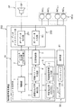
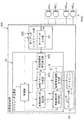
- FIG. 1 is a block diagram illustrating a configuration of an object arrangement estimation apparatus according to the first embodiment.
- the object arrangement estimation apparatus according to the first embodiment includes a central processing unit (CPU) 11 that can perform predetermined data processing by executing a program, a read-only memory (ROM) 12 that stores a program, A random access memory (RAM) 13 for storing various data, a hard disk drive (HDD) 21 as an auxiliary storage device, a display 31 as an output device, a keyboard 32 and a mouse 33 as input devices, It has a time measuring unit 41 that measures time, and an audio interface unit 50 that includes an audio output unit 51 and an audio input unit 52 that are input / output interfaces with an external audio device (speaker or microphone).
- the audio interface unit 50 includes a speaker array SPa composed of N external speakers (SP 1 , SP 2 ,..., SP N ) and M external microphones (MC 1 , MC 2 ,. M )) is connected to the microphone array MCa.
- CPU 11 CPU 11, ROM 12, and RAM 13 constitute computer main part 10.
- Display 31, keyboard 32, and mouse 33 constitute user interface unit 30.
- the user interface unit 30 may be configured by a display panel with a touch panel function.
- FIG. 2 is a block diagram in which functional blocks realized by the computer main part 10 of the object arrangement estimation apparatus 100 according to the first embodiment are specified.
- the CPU 11 of the computer main unit 10 reads out and executes the object placement estimation program stored in the ROM 12, thereby executing a control unit 1, an impulse generation unit (TSP generation unit) 2, a response detection unit 3, a feature vector generation unit 4, It can operate as the dissimilarity matrix deriving unit 5, the placement deriving unit (MDS unit) 6, and the arrangement estimation result output unit 7.
- the cloth placement deriving unit (MDS unit) 6 and the arrangement estimation result output unit 7 constitute an estimation unit 8.
- the object placement estimation program is not necessarily stored in the ROM 12.
- the object placement estimation program may be stored in the HDD 21 (FIG. 1), and read and executed as appropriate by the CPU 11. Further, the object arrangement estimation program may be appropriately downloaded from an external storage device (not shown) via a network (not shown) and executed by the CPU 11. Alternatively, the object arrangement estimation program may be stored in a portable storage medium such as a flexible disk, an optical disk, or a flash memory (not shown). In that case, the program stored in the portable storage medium may be read from the medium by the CPU 11 and executed. Alternatively, it may be installed in the HDD 21 or the like before execution.
- the control unit 1 is realized by the CPU 11 executing the object placement estimation program.
- the control unit 1 monitors the progress of the operation related to the object arrangement estimation and controls the entire apparatus 100.
- the impulse generator (TSP generator) 2 is realized by the CPU 11 executing an object arrangement estimation program.
- the impulse generator (TSP generator) 2 selectively generates and outputs a signal for outputting a predetermined acoustic wave to one or a plurality of speakers of the speaker array SPa connected to the audio output unit 51.
- the signal is, for example, a signal (TSP signal) having a pulse-shaped waveform (time-extended pulse waveform (TSP waveform)).
- the response detection unit 3 is realized by the CPU 11 executing the object arrangement estimation program.
- the response detection unit 3 outputs, for each of the M inputs from the M microphones of the microphone array MCa connected to the audio input unit 52, the above-described predetermined acoustic wave (for example, a speaker according to the TSP signal).
- the response waveform for the acoustic TSP wave is detected (the impulse response waveform for the acoustic TSP wave is detected), and the time (acoustic wave arrival time) when the response waveform is detected in each of the M microphones with reference to the time measuring unit 41 is detected. Identify.
- the feature vector generation unit 4 is realized by the CPU 11 executing the object arrangement estimation program.
- the feature vector generation unit 4 inputs the acoustic wave arrival time specified by the response detection unit 3, and generates an N-dimensional feature vector for each of the M microphones (objects).
- the dissimilarity matrix deriving unit 5 is realized by the CPU 11 executing the object arrangement estimation program.
- the dissimilarity matrix deriving unit 5 obtains a norm between the feature vectors of the two microphones for any two objects (microphones) of the M microphones. Then, the dissimilarity matrix deriving unit 5 derives an M-by-M dissimilarity matrix having the obtained norm as an element.
- the cloth placement deriving unit (MDS unit) 6 is realized by the CPU 11 executing the object placement estimation program.
- the placement deriving unit (MDS unit) 6 derives placement in the real space of M microphones based on the dissimilarity matrix.
- the cloth placement deriving section (MDS section) 6 derives the placement of M microphones, for example, by applying multidimensional scaling (MDS) to the dissimilarity matrix.
- MDS multidimensional scaling
- the arrangement estimation result output unit 7 is realized by the CPU 11 executing the object arrangement estimation program.
- the placement estimation result output unit 7 performs linear transformation operations such as enlargement / reduction and rotation on the placement derived by the placement placement unit 6, estimates the placement of M microphones in real space, and outputs the result as a placement estimation result. To do.
- the cloth placement deriving unit (MDS unit) 6 and the arrangement estimation result output unit 7 constitute an estimation unit 8 of the object arrangement estimation apparatus according to the present embodiment.
- control part 1 the impulse generation part (TSP generation part) 2, the response detection part 3, the feature vector generation part 4, the dissimilarity matrix derivation part 5, the placement derivation part (MDS part) 6, and the arrangement estimation result output part 7
- TSP generation part the impulse generation part
- MDS part placement derivation part
- arrangement estimation result output part 7 At least one of the above may be realized by a dedicated hardware circuit.
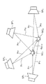
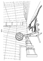
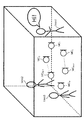
- FIG. 3 is a schematic diagram showing the relationship between M microphones as objects of arrangement estimation, N speakers arranged at positions corresponding to reference points, and various quantities.
- M microphones for simplicity, only two microphones (MC 1 , MC 2 ) and four speakers (SP 1 , SP 2 , SP 3 , SP 4 ) are shown.
- p ij indicates the time (acoustic wave arrival time) when the acoustic wave (TSP wave) emitted from the i-th speaker SP i reaches the j-th microphone (MC j ).
- d MC12 is No. 1 of N acoustic wave arrival at the microphone MC 1 Time p i1: 1 No.
- the norm between the N-th feature vector p MC2 of the second microphone MC 2 having N acoustic wave arrival times p i2 (i: 1 to N) as components is shown.
- the norm here is, for example, the Euclidean norm.
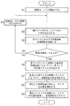
- FIG. 4 is a flowchart of processing for estimating microphone placement performed by the object placement estimating apparatus.
- the control unit 1 (CPU 11) of the object arrangement estimation apparatus sets the variable i to 1 and stores the variable i in the RAM 13 as an initial setting operation (S1).
- the impulse generator 2 (CPU 11) reads the value of the variable i and the TSP waveform stored in the RAM 13, and outputs the TSP waveform to the i-th speaker SP i connected via the audio output unit 51.
- FIG. 5 shows that the acoustic wave TSP emitted from the i-th speaker SP i is collected by each microphone (MC 1 , MC 2 ,..., MC j ,..., MC M ⁇ 1 , MC M ).
- FIG. next to the time chart of the i-th speaker SP i is, i th illustrates an acoustic TSP wave output from the speaker SP i, each microphone (MC 1, MC 2, ⁇ , MC j, ⁇ , MC M- 1 , MC M ) is a time chart next to signals output from the respective time charts.
- step S2 when an acoustic wave signal is input to the i-th speaker SP i , a predetermined acoustic wave TSP is output from the speaker to the air.
- the acoustic wave propagates through the air at the speed of sound, and is picked up by each microphone (MC 1 , MC 2 ,..., MC j ,..., MC M ⁇ 1 , MC M ).
- each microphone MC 1 , MC 2 ,..., MC j ,..., MC M ⁇ 1 , MC M .
- a response waveform R i1 to the acoustic wave appears in the vicinity of the time p i1 on the time coordinate T i .
- a response waveform R ij to the acoustic wave appears near the time p ij .
- Outputs from the microphones (MC 1 , MC 2 ,..., MC j ,..., MC M ⁇ 1 , MC M ) are stored in the RAM 13.
- the response detection unit 3 (CPU 11) outputs the output of each microphone (MC 1 , MC 2 ,..., MC j ,..., MC M ⁇ 1 , MC M ) to the audio input unit 52.
- the time when the response waveform peak appears at each output is specified as the acoustic wave arrival time p ij on the time coordinate axis T i for the microphone MC j (j: 1 to M). (S3).
- the acoustic wave arrival time may be determined based on other characteristics of the response waveform (rising timing, timing exceeding a predetermined sound pressure level, etc.).
- the identified acoustic wave arrival time is stored in the RAM 13.
- control unit 1 determines whether or not the value of the variable i is greater than or equal to N. If the value of i is less than N, the process returns to step S2 via step S5. On the other hand, if the value of i is N or more, the process proceeds to step S6.
- step S5 the value of variable i is advanced by 1 (i ⁇ i + 1), and the new value of variable i is stored in RAM 13. Accordingly, in step S2 to be executed next, an acoustic TSP wave is emitted from the speaker SP (i + 1) of the number next to the speaker from which the acoustic wave was emitted in the previous step S2, and each microphone (MC 1 , MC 2 ,..., MC j ,..., MC M ⁇ 1 , MC M ) are collected and output as response waveforms.
- step S3 the response detection unit 3 uses the time coordinate axis T i + 1 to calculate the acoustic wave arrival time p i + 1, j in each microphone MC j (j: 1 to M) for the acoustic TSP wave emitted from the speaker. Identify.
- the time coordinate axis T i which is a scale used for specifying the arrival time of the acoustic wave from the i-th speaker SP i and the arrival time of the acoustic wave from the (i + 1) -th speaker SP i + 1 were used.
- the time coordinate axis T i + 1 which is a scale may be the same or different from each other.
- the object arrangement estimation apparatus is emitted from each speaker (SP 1 , SP 2 ,..., SP N ⁇ 1 , SP N ) by repeating the processes of steps S2 to S5 N times.
- Time p ij (i: 1 to N, j: 1 to M) when the acoustic wave reaches each microphone (MC 1 , MC 2 ,..., MC j ,..., MC M ⁇ 1 , MC M ) )
- MC 1 , MC 2 ,..., MC j ,..., MC M ⁇ 1 , MC M )
- the response detection unit 3 includes each microphone (MC 1 , MC 2 ,..., MC j ,..., MC M ⁇ 1 , MC It is only necessary to specify the time on an arbitrary time coordinate axis when the acoustic wave arrives at M ), and the acoustic wave is actually transmitted to each speaker (SP 1 , SP 2 ,..., SP N-1 , SP N ) From each microphone (MC 1 , MC 2 ,..., MC j ,..., MC M ⁇ 1 , MC M ) is not required to be obtained.
- the object arrangement estimation apparatus it is not necessary to specify the time at which the acoustic wave is emitted from each speaker (SP 1 , SP 2 ,..., SP N ⁇ 1 , SP N ). Therefore, in this object arrangement estimation apparatus, the object arrangement estimation is caused due to an error related to specifying the time at which the acoustic wave is emitted from each speaker (SP 1 , SP 2 ,..., SP N ⁇ 1 , SP N ). There is no error in the results.
- the feature vector generation unit 4 (CPU 11) inputs the acoustic wave arrival time (p ij (i: 1 to N, j: 1 to M)) specified by the response detection unit 3, and M microphones MC For each j (j: 1 to M), an N-dimensional feature vector p MCj is generated (S6).
- the generated feature vector p MCj is stored in the RAM 13.
- the N-dimensional feature vector p MCj represents the feature of the position of the j-th microphone MC j in the real space with an N-dimensional scale representing the proximity to each of the N speakers SP i (i: 1 to N). Is. Specifically, the feature vector p MCj is It is. That is, the scale representing the proximity to the i-th speaker SP i (i: 1 to N) is the time when the acoustic wave arrives at each microphone MC j (j: 1 to M) from the i-th speaker SP i. Is the time coordinate axis T i (FIG.
- the measure for the j-th microphone MC j in each scale is used by the response detection unit 3 to specify the acoustic wave arrival time. This is the acoustic wave arrival time p ij on the time coordinate axis T i that was present (FIG. 5).
- the N scales used to construct the N-dimensional feature vector need not be the time coordinate axis.
- the scale may be a real space distance.
- the scale may be the peak level of the response waveform detected at each microphone.
- the scale may be a quantity that represents the characteristic of the shape of the response waveform detected in each microphone.
- the scale may be an amount representing the characteristics of the indirect sound (reverberation component) detected in each microphone.
- the dissimilarity matrix deriving unit 5 (CPU 11) generates the dissimilarity matrix based on the N-dimensional feature vector p MCj for the M microphones generated by the feature vector generating unit 4 and stored in the RAM 13. D is generated (S7). The generated dissimilarity matrix D is stored in the RAM 13.
- the dissimilarity matrix D is a feature vector (p) for every two combinations (for example, microphone MC k and microphone MC l ) of M microphones MC j (j: 1 to M) that are objects of arrangement estimation. a matrix of M rows and M columns for the norm d MCkl of MCk and p MCl) as elements.
- each element d MCkl is It is.
- the dissimilarity matrix Is obtained by determining the dissimilarity of the positions of two microphones in the real space based on the N-dimensional feature vector P MCj (j: 1 to M). It is a matrix which shows a similarity degree.
- the placement derivation unit (MDS unit) 6 (CPU 11) derives the placement of M microphones by applying a multidimensional scaling (MDS) to the dissimilarity matrix D.
- MDS multidimensional scaling
- the cloth placement deriving unit (MDS unit) 6 first has an M ⁇ M matrix D (2) having d MCkl 2 as an element. Ask for.
- the cloth placement deriving unit (MDS unit) 6 uses the Kronecker delta ⁇ kl , and An M ⁇ M centering matrix H having h kl as elements Is used to obtain an M ⁇ M matrix B represented by the following equation.
- the placement matrix X derived by the placement placement unit (MDS unit) 6 is obtained by adding linear transformation (enlargement / reduction, rotation, inversion (mirroring), etc.) to the actual arrangement of M microphones. There may be. Therefore, the arrangement estimation result output unit 7 reads out the arrangement matrix X derived by the arrangement deriving unit (MDS unit) 6 from the RAM 13 and performs an appropriate linear transformation on the arrangement matrix X to determine the actual arrangement of M microphones. The determined arrangement is stored in the RAM 13.
- the arrangement estimation result output unit 7 obtains the arrangement variance of the arrangement matrix X for each coordinate axis of the arrangement matrix X, and the arrangement matrix X
- the values of the three coordinate axes of the configuration matrix are enlarged / reduced so that the variance of the configuration of any of the three coordinate axes coincides with the known variance.
- the arrangement estimation result output unit 7 has the placement matrix X.
- the configuration values of the three coordinate axes of the configuration matrix are enlarged or reduced so that the configuration values of the two microphones having the most spaced configuration values about the coordinate axes coincide with the known distance.
- the arrangement estimation result output unit 7 is based on information that is known about the position of the arrangement estimation object in the real space (for example, information on the position of any three objects in the real space). It is possible to perform linear transformation on the placement matrix X and estimate and output the arrangement of the arrangement estimation object in the real space.
- the placement indicated by the placement matrix X and the coordinates in the real space may have a mirror image relationship.
- the placement estimation result output unit 7 may invert the value of any one coordinate axis of the placement matrix X to match the placement of the placement matrix X with the coordinates in the real space.
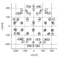
- the 80-channel microphone array MCa was placed in a sound field reproduction environment in which 96-channel speaker arrays (SPa1, SPa2, SPa3, SPa4) were arranged.
- the microphone array MCa is formed by disposing one omnidirectional microphone (DPA 4060-BM) at each node in a frame structure having a C80 fullerene structure and a diameter of about 46 centimeters.
- the sound field reproduction environment consisting of a 96-channel speaker system consists of 90 speakers (Fostex FE103En) built in a rectangular parallelepiped enclosure attached to the wall of a room with a regular hexagonal horizontal section and 6 on the ceiling. .
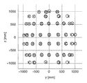
- FIG. 7A, 7B, and 7C show the results of the experiment.
- Each of these figures is a view of the results viewed from directly above, directly in front, and directly beside (a direction rotated 90 degrees horizontally from directly in front).
- the actual microphone position is indicated by a cross
- the placement estimation result is indicated by a circle.
- the object arrangement estimation apparatus can output the estimation result with sufficient accuracy for determining the microphone arrangement and the correctness of the cable connection.
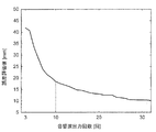
- FIG. 8 is a graph in which the results are plotted with the horizontal axis as the number of speakers and the vertical axis as the above-described error evaluation values for the respective estimation results. From FIG. 8, it was found that in this embodiment, the accuracy of the object placement estimation is monotonously improved by increasing the number of speakers used for the object placement estimation (the number of reference points described above). In particular, it can be seen that the accuracy of object placement estimation is significantly improved until the number of speakers exceeds 10. From this, it was found that in the object arrangement estimation according to the present embodiment, the arrangement estimation result can be obtained with good accuracy by setting the number of speakers (the number of reference points described above) to about 10 or more.
- the object placement estimation apparatus uses M microphones placed at positions corresponding to N reference points to arrange M speakers. It is also possible to estimate.
- the principle of speaker placement estimation and the experimental results will be described with reference to FIGS.
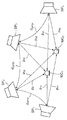
- FIG. 9 is a schematic diagram showing the relationship among M speakers as objects of arrangement estimation, N microphones arranged at positions corresponding to reference points, and various quantities.
- M speakers arranged at positions corresponding to reference points, and various quantities.
- MC 1 , MC 2 only two microphones
- SP 1 , SP 2 , SP 3 , SP 4 four speakers
- p ij indicates the time (acoustic wave arrival time) when the acoustic wave (TSP wave) emitted from the i-th speaker SP i reaches the j-th microphone (MC j ).
- d SP12 indicates the time (acoustic wave arrival time) p 1j (j: 1 to N) when the acoustic wave emitted from the first speaker SP 1 reaches each of the N microphones MC j (j: 1 to N).
- d SP23 and d SP34 are respectively the norm between the N-dimensional feature vector p SP2 of the second speaker SP 2 and the N-dimensional feature vector p SP3 of the third speaker SP 3 and the third speaker.
- the norm between the N-dimensional feature vector p SP3 of SP 3 and the N-dimensional feature vector p SP4 of the fourth speaker SP 4 is shown.
- the feature vector generation unit 4 determines the positions at which the microphones MC j (j: 1 to N) are arranged for the M speakers SP i (i: 1 to M) that are the arrangement estimation objects.
- a feature vector p SPi (i: 1 to M) is generated for each speaker SP i (i: 1 to M) on the assumption that it is the above reference point, and the position in the real space for the M speakers from the M feature vectors.
- the dissimilarity matrix is derived, and the arrangement of the speakers in the real space is estimated from the dissimilarity matrix.
- the N-dimensional feature vector p SPi represents the feature of the position of the i-th speaker SP i in the real space and represents the proximity to each of the N microphones MC j (i: 1 to N). It is a scale. Specifically, the feature vector p SPi is It is.
- the dissimilarity matrix deriving unit 5 obtains a norm between the feature vectors of the two speakers with respect to any combination of two objects among the M speakers. Then, the dissimilarity matrix deriving unit 5 derives an M-by-M dissimilarity matrix having the obtained norm as an element.
- the dissimilarity matrix deriving unit 5 (CPU 11) generates a dissimilarity matrix D based on the N-dimensional feature vector pSPi .
- each element d MCkl of the dissimilarity matrix D is It becomes.
- the dissimilarity matrix Is obtained by determining the dissimilarity of the positions of the two speakers in the real space based on the N-dimensional feature vector P SPi (i: 1 to M). It is a matrix which shows a similarity degree.
- the placement derivation unit (MDS unit) 6 (CPU 11) derives the placement of M speakers by applying a multidimensional scaling (MDS) to the dissimilarity matrix D.
- MDS multidimensional scaling
- the placement estimation result output unit 7 performs an appropriate linear transformation on the placement matrix X derived by the placement placement unit (MDS unit) 6 to determine the actual placement of the M speakers.
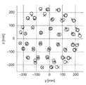
- FIG. 10A, FIG. 10B, and FIG. 10C show the results of the experiment.
- Each of these figures is a view of the results viewed from directly above, directly in front, and directly beside (a direction rotated 90 degrees horizontally from directly in front).
- the actual speaker position is indicated by a cross
- the placement estimation result is indicated by a circle.
- the error evaluation value was 23.5486 [mm]. Compared with the error evaluation value of 4.8746 [mm] in the microphone placement estimation experiment conducted in the same experimental environment, this value has a large error.
- the speaker arrangement is estimated based on the speaker arrangement and the cable. It can be said that it has sufficient accuracy for determining the correctness of the connection.
- Second embodiment 3-1 Configuration
- the second embodiment of the present invention is improved in portability in comparison with the first embodiment, and can easily and accurately check the arrangement of the microphone array and the cable connection in various sound collection sites. It is an estimation device.
- FIG. 11 and FIG. 12 are block diagrams showing the configuration of the object arrangement estimation apparatus according to the second embodiment.
- the object arrangement estimation apparatus according to the second embodiment has a configuration equivalent to that of the object arrangement estimation apparatus according to the first embodiment.
- the audio interface unit 250 including the audio output unit 251 has one external speaker SP (SP 1 ) Is different from the object arrangement estimation apparatus according to the first embodiment.
- the speaker SP is, for example, a small speaker (for example, Audio-Technica AT-SPG50) having excellent portability.
- a predetermined acoustic wave is output using one speaker SP 1 , and the speaker SP 1 is moved after the acoustic wave is output, whereby predetermined positions are determined at a plurality of positions.
- An acoustic wave is output, and for each acoustic wave, a response waveform in each of the M microphones MC j (j: 1 to M) is detected, and the acoustic wave arrival time is measured.
- the acoustic waves are output from the speaker SP 1 at N positions, so that N microphones MC j (j: 1 to M) are obtained in the same manner as in the first embodiment.
- An N-dimensional feature vector using a scale representing the proximity to the reference point is generated.
- the number of speakers in the present embodiment is not limited to one and may be plural.
- the object arrangement estimation apparatus measures the arrival time of a predetermined acoustic wave from one speaker SP 1 at each microphone MC j (j: 1 to M) and, for convenience, predetermined positions from N positions.
- the arrival time of the acoustic wave is measured at each microphone MC j (j: 1 to M).
- the N positions here correspond to the above-mentioned reference points.
- the feature vector generation unit 4 generates a feature vector p MCj (j: 1 to M) for each microphone MC j (j: 1 to M), as in the first embodiment.
- the dissimilarity matrix deriving unit 5 derives the dissimilarity matrix D from the generated feature vector p MCj (j: 1 to M) in the same manner as in the first embodiment, and the estimating unit 8 (the placement deriving unit 6
- the arrangement estimation result output unit 7) estimates the arrangement of the M microphones in the real space from the dissimilarity matrix D and outputs it.
- the object arrangement estimation apparatus is superior in portability in that it does not use a large-scale speaker array SPa as compared with the object arrangement estimation apparatus according to the first embodiment. This is advantageous in that the microphone arrangement can be estimated at the sound collection site.
- an 80-channel microphone array MCa is placed near the altar of the St. Mary's Cathedral in Tokyo Cathedral, and a speaker SP 1 (Audio Technica AT-SPG50) (not shown) is used by hand.
- the acoustic wave was output while moving it to various positions.
- the conditions for acoustic wave output and detection were TSP length 8192 [pnt], TSP response length 105600 [pnt], sampling frequency 48000 [Hz], and quantization bit rate 16 [bit].
- FIG. 14A, FIG. 14B, and FIG. 14C show the results of the experiment.
- Each of these figures is a view of the results viewed from directly above, directly in front, and directly beside (a direction rotated 90 degrees horizontally from directly in front).
- the actual microphone position is indicated by a cross
- the placement estimation result is indicated by a circle.
- the object location estimation apparatus can output the estimation result with sufficient accuracy for determining the microphone placement and the correctness of the cable connection.
- FIG. 15 is a graph in which the result is plotted with the horizontal axis as the number of acoustic wave outputs and the vertical axis as the above-described error evaluation value for each estimation result. From FIG. 15, it was found that the accuracy of the object arrangement estimation monotonously also increases in this embodiment by increasing the number of times (the number of reference points described above) to output the acoustic wave used for the object arrangement estimation.
- the accuracy of object placement estimation is significantly improved until the number of speakers exceeds 10. Therefore, even in the sound collection site when content is actually created, according to the object arrangement estimation according to the present embodiment, the number of acoustic wave outputs (that is, the number of reference points described above) is about 10 or more. Thus, it was found that the placement estimation result can be obtained with good accuracy.
- Modification of Object Placement Estimation Device relates to another example of a feature vector generation method.
- Modification 2 relates to another example of a method for estimating the placement of an object from a dissimilarity matrix.
- Modifications 1 and 2 are modifications that can be applied individually and simultaneously to both the object arrangement estimation apparatuses of the first and second embodiments.
- Modification 1 (Examples by feature vector generation method)
- the feature vector is generated based on the time (acoustic wave arrival time) when the acoustic wave emitted from the speaker located at the reference point reaches the microphone.
- the feature vector is determined based on the frequency amplitude characteristic of the output signal output from the microphone.
- FIG. 16 is a block diagram showing a configuration of a modification of the object arrangement estimation apparatus. Note that the same reference numerals are given to the same components as those shown in FIG. 1 and the like, and a description thereof will be omitted.
- the modification of the object arrangement estimation apparatus has a configuration in which the timer unit 41 and the audio output unit 51 are omitted from the object arrangement estimation apparatus illustrated in FIG.
- a speaker array SPa composed of external speakers (SP1, SP2,..., SPN) may not be connected to the present apparatus.
- FIG. 17 is a block diagram in which functional blocks realized by the computer main part 10 of the object arrangement estimation apparatus 300 are clearly shown.
- the CPU 11 of the computer main unit 10 reads out and executes the object arrangement estimation program stored in the ROM 12, thereby executing the control unit 1, the frequency amplitude characteristic calculation unit 303, the feature vector generation unit 304, the dissimilarity matrix derivation unit 5, It can operate as a cloth placement deriving unit (MDS unit) 6 and an arrangement estimation result output unit 7.
- the cloth placement deriving unit (MDS unit) 6 and the arrangement estimation result output unit 7 constitute an estimation unit 8.
- the operations of the control unit 1, the dissimilarity matrix deriving unit 5, the placement placement deriving unit (MDS unit) 6, and the estimating unit 8 may be the same as those described in the first and second embodiments. The description is omitted.
- the frequency / amplitude characteristic calculation unit 303 is realized by the CPU 11 executing the object arrangement estimation program.
- the frequency amplitude characteristic calculation unit 303 calculates the frequency amplitude characteristic for each output signal of the microphones (MC 1 to MC M ) included in the microphone array MCa.
- the feature vector generation unit 304 is realized by the CPU 11 executing an object arrangement estimation program.
- the feature vector generation unit 304 can input the frequency amplitude characteristic calculated by the frequency amplitude characteristic calculation unit 303 and generate an N-dimensional feature vector for each of the M microphones (objects).
- the feature vector generation unit 304 determines the difference between the corresponding components of the feature vectors of any two microphones of the M microphones (objects) based on the frequency amplitude characteristics (features in the equation (1)).
- the difference in vector components p i, j ⁇ p i, k , k: k ⁇ j, i is an arbitrary integer from 1 to N will be described in detail.
- the method by which the generation unit 304 determines the feature vector itself of each microphone can also be understood from the following description.
- control unit 1 the frequency amplitude characteristic calculation unit 303, the feature vector generation unit 304, the dissimilarity matrix derivation unit 5, the cloth placement derivation unit (MDS unit) 6, and the arrangement estimation result output unit 7 is It may be realized by a dedicated hardware circuit.
- FIG. 18 is a schematic diagram showing a state where three people hmn1 to hmn3 are having a meeting indoors.
- M microphones MC 1 to MC M
- M microphones are connected to an object arrangement estimation apparatus 300 (not shown) via an audio interface unit 350 (not shown) (see FIG. 17).
- FIG. 19 is a flowchart of a process for estimating the microphone arrangement performed by the object arrangement estimating apparatus 300.
- the frequency amplitude characteristic calculation unit 303 of the object arrangement estimation apparatus 300 receives output signals of M microphones (MC 1 to MC M ) via the audio interface unit 350. These output signals are response signals of the respective microphones for the ambient environmental sound in the room.
- the frequency / amplitude characteristic calculation unit 303 extracts, for each output signal, a portion in which the human environment voice is included in the ambient environmental sound (for example, a portion in which the voice “Hi!” Of the speaker hmn1 in FIG. 18 is included).
- Each of the output signals (time domain) extracted from the microphones (MC 1 to MC M ) is converted into the frequency domain, and the frequency amplitude characteristic is calculated from the output signal (frequency domain) (step S101).
- Information regarding the frequency amplitude characteristics of the output signals of the microphones (MC 1 to MC M ) is sent from the frequency amplitude characteristic calculation unit 303 to the feature vector generation unit 304.
- the feature vector generation unit 304 calculates the difference between the frequency amplitude characteristics of the output signal for any combination of two microphones (MC j , MC k ) based on the information regarding the frequency amplitude characteristics sent from the frequency amplitude characteristic calculation unit 303. Calculate (step S102).
- the feature vector generation unit 304 determines the position of the two microphones relative to the speaker (reference point).
- the difference between the two microphone measures on a scale that defines the similarity, that is, the proximity to the reference point (pi , j ⁇ pi , k in equation (1), k: k ⁇ j, where i is 1 to Any integer of N.)
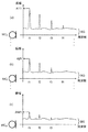
- FIG. 20 is a schematic diagram showing frequency amplitude characteristics of output signals of the microphones (MC 1 to MC M ).
- 20 (a) is in the room as shown in FIG. 18, a frequency amplitude characteristic of the output signal from the microphone MC 1 for ambient sounds including voices human hmn1 uttered.
- FIG. 20B and FIG. 20C are frequency amplitude characteristics of output signals from the microphones MC j and MC M for the same ambient environmental sound including the same voice, respectively.
- a formant of a voice uttered by a person hmn1 appears in a form superimposed on a component BG of noise ubiquitous in the sound collection environment (such as indoor reverberation sound or outdoor hustle sound).
- the center frequency of the first formant F1 is shown as f1
- the center frequencies of the formants after the second formant are shown as f2, f3, and f4, respectively.
- the noise component BG shows almost the same profile in each output signal, while the formant component of human voice is the frequency of the original formant as the microphone moves away from the person. Move away from the shape of the amplitude characteristic.
- the feature vector generation unit 304 can determine the difference in proximity to the speaker (reference point) for the two microphones from the difference in the shape of the frequency amplitude characteristics of the output signals of the two microphones.
- the feature vector generation unit 304 integrates the difference between the frequency amplitude characteristics of the output signals of the two microphones (MC j , MC k , k: k ⁇ j) on the frequency axis (step S103).
- the integral value obtained here is the difference in proximity of the microphone MC j and the microphone MC k to the reference point (speaker), that is, the component vector related to the reference point in the feature vector of the two microphones (MC j , MC k ).
- Difference (pi , j- pi , k in equation (1), k: k ⁇ j, i is an arbitrary integer from 1 to N).
- the feature vector generation unit 304 obtains the component of each feature vector from the difference between the components related to the speaker (reference point) in the feature vectors of the two microphones thus obtained. You can also.
- step S103 the feature vector generation unit 304, for every two microphones of the microphones (MC 1 to MC M ), the dissimilarity (corresponding to the feature vectors) of the positions of the two microphones with respect to each reference point Difference between components to be determined).
- step S104 the dissimilarity matrix deriving unit 5 determines the dissimilarity matrix D (formula (3)) based on the difference between the corresponding components of any two feature vectors obtained by the feature vector generating unit 304. Is derived.
- the feature vector generation unit 304 may obtain a feature vector of each microphone from the integration value obtained in step S103 and output the feature vector to the similarity matrix deriving unit 5.
- the dissimilarity matrix deriving unit 5 may derive the dissimilarity matrix in step S104 in the same manner as in step S7 in the previous embodiment.
- step S105 and step S106 Since the processing in step S105 and step S106 is the same as that described in the previous embodiment (step S8 and step S9 in FIG. 4), description thereof is omitted here.
- the object arrangement estimating apparatus collects voices uttered by a speaker at different N (N is 3 or more) positions using M microphones, and the sound is collected and output by each microphone.
- a dissimilarity matrix D is derived using the output signal (step S104). Persons speaking at N (N is 3 or more) positions may not be the same person.
- the feature vector generation unit 304 may generate a feature vector as follows based on the information regarding the frequency amplitude characteristic sent from the frequency amplitude characteristic calculation unit 303. First, the feature vector generation unit 304 may specify the formant of the speaker for the output signal of each microphone (MC 1 to MC M ), and may determine the amplitude of the specified formant (for example, the first formant F1). . The feature vector generation unit 304 then determines the peak amplitude of each specific formant (for example, the first formant F1 having the center frequency f1) that appears in the frequency amplitude characteristics of the output signals of the microphones (MC 1 to MC M ). The ratio (unit is, for example, decibel) with the amplitude (the amplitude A1f1 shown in FIG.
- a measure for each microphone (MC 1 -MC M ) on a scale representing the proximity to the reference point (person hmn1) may be determined.
- the amplitude AMf1 peak of the first formant F1 in frequency-amplitude characteristics of the output signal of the microphone MC M the peak of the first formant F1 in frequency-amplitude characteristics of the output signal of the microphone MC 1 as any one microphone
- the measure for the microphone MC 1 on the scale representing the proximity to the person hmn1 as the reference point is, for example, 1, and the proximity to the reference point (person hmn1) is it may be set as 2 to measure for the microphone MC M in measure of.
- the feature vector generation unit 304 can determine the feature vector of each microphone (MC 1 to MC M ) based on the specific frequency component of the frequency amplitude characteristic.
- the object arrangement estimation apparatus 300 does not need to output a specific acoustic wave. Moreover, this modification is particularly suitable for estimating an object arrangement in a room having acoustic characteristics that can provide rich reverberation or in a crowd.
- Modified example 2 (examples for different object placement estimation methods)
- the estimation unit 8 (FIG. 2 and the like) including the placement derivation unit 6 estimates the placement of the object by applying the MDS method to the dissimilarity matrix.
- the placement of the object can be estimated by a method other than the MDS method.
- the placement derivation unit 6 may obtain a placement (an approximate solution) by numerically solving a so-called combination optimization problem using a full search method. That is, the placement deriving unit 6 (FIG. 2 and the like) sets the degree of similarity as the placement approximate solution for all the placements (placement approximate solution candidates) of a plurality of possible objects (for example, M microphones).
- the placement approximation solution candidate evaluated based on the matrix and having the highest evaluation may be output as the placement estimation result.
- the configuration derivation unit 6 uses a so-called genetic algorithm (Genetic Algorithm) algorithm to solve the combinatorial optimization problem numerically by a local search method, thereby approximating the configuration ( Solution). That is, the placement derivation unit 6 (FIG. 2 and the like) has a similar degree of fitness as a placement approximation solution for some of the placements (placement approximate solution candidates) of a plurality of possible objects (for example, M microphones). Evaluation may be performed based on the degree matrix, and the placement approximation solution candidate having the highest evaluation among the evaluated placement approximation solution candidates may be output as the placement estimation result.
- Genetic Algorithm Genetic Algorithm
- information on the position of the position estimation target object and the position of the reference point is not essential for estimating the position of the target object.
- the conditions regarding the position where the location estimation target object or the reference point may exist are set in advance and set.
- the position where the object can exist can be discretized.
- the minimum interval d min as a condition for a position where the placement estimation target object can exist, the number of possible placement approximate solution candidates can be reduced, and the speed of derivation of the placement approximate solution can be increased.
- the spatial range in which the target object can exist is limited by using information on any one reference point, the distance to the closest object, and the distance from the reference point to the farthest object. Thus, the number of laying approximate solution candidates can be dramatically reduced.
- the time (acoustic wave arrival time) when the acoustic wave emitted from the speaker located at the reference point reaches each microphone is specified, and the feature vector is generated.
- the time when the acoustic wave is emitted from the speaker located at the reference point is specified, and the time required for the acoustic wave to reach each microphone by doing so (acoustic wave propagation time) You may ask for.
- the microphone that recorded the shortest acoustic wave propagation time among the acoustic wave propagation times from a speaker at a certain reference point to each object (microphone) is the microphone closest to the reference point, and the longest acoustic wave propagation time. Is the microphone farthest from the reference point.
- the product of the shortest acoustic wave propagation time and the sound speed is the minimum distance R min
- the product of the longest acoustic wave propagation time and the sound speed is the longest distance R max
- the possible positions are limited to a range of distances from the reference point to R min and R max .
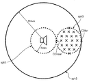
- FIG. 21 shows object position candidate points when a minimum inter-object distance d min , a minimum distance R min from a certain reference point, and a longest distance R max are given as conditions for the position where an arrangement estimation object can exist. It is a figure which shows CD (x mark in a figure).
- Object position candidate point CD reference points inside the sphere sph2 radius R max of the outer and center the same reference points of a sphere sph1 radius R min around the (speaker in the figure), the minimum distance d Distributed after min .
- the placement derivation unit 6 (FIG. 2 and the like) is dissimilar for each of the placement approximate solution candidates configured by selecting the number (M) of candidate points from the target position candidate points CD.
- the fitness as a placement approximation solution is evaluated, and a placement approximation solution candidate with good evaluation may be used as a placement approximation solution.
- a placement approximation solution candidate with good evaluation may be used as a placement approximation solution.
- the full search method it is only necessary to evaluate the fitness of all possible placement approximate solution candidates.
- a placement approximation solution candidate to be evaluated may be selected according to a known algorithm (genetic algorithm or the like).
- ⁇ Evaluation of conformity may be performed as follows. First, a distance between objects is obtained by calculation with respect to a placement approximation solution candidate to be evaluated, and a distance matrix in which each element is composed of distances between objects is derived based on the calculation result. Next, the fitness can be evaluated by evaluating the similarity between the distance matrix thus calculated and the dissimilarity matrix. That is, the relationship between the dissimilarity matrix and the distance matrix can be evaluated higher by evaluating a distance matrix that is close to a proportional relationship, so that the fitness of the placement approximate solution candidate can be evaluated.
- FIG. 22 is a diagram showing object position candidate points CD (marked with x in the figure) when the condition that the microphone as the object constitutes a linear microphone array is added.
- the object position candidate points CD are distributed only on the straight line L in contact with the sphere sph1 at the candidate point CD near . Further, it is highly likely that the microphone having the shortest acoustic wave propagation time and the microphone having the longest acoustic wave propagation time are positioned at the candidate point CD near and the candidate point CD far on the spherical surface of the sphere sph2.
- FIG. 23 is a diagram showing object position candidate points CD (marked with x in the figure) when a condition is added that a microphone as an object forms a planar microphone array.
- the object position candidate points CD are distributed only on the circle C in contact with the sphere sph1 at the candidate point CD near .
- the microphone having the shortest acoustic wave propagation time and the microphone having the longest acoustic wave propagation time are positioned at the candidate point CD near and the candidate point CD far on the spherical surface of the sphere sph2. Therefore, it is possible to speed up the derivation of the placement approximate solution by selecting the placement approximate solution candidate having such a microphone arrangement and performing a local search.
- FIG. 24 is a diagram showing object position candidate points CD (marked with x in the figure) when a condition is added that a microphone as an object forms a square microphone array.
- the object position candidate points CD are distributed only on the square SQ inscribed in the circle C in contact with the sphere sph1 at the candidate point CD near .
- the microphone having the shortest acoustic wave propagation time and the microphone having the longest acoustic wave propagation time are positioned at the candidate point CD near and the candidate point CD far on the spherical surface of the sphere sph2. Therefore, it is possible to speed up the derivation of the placement approximate solution by selecting the placement approximate solution candidate having such a microphone arrangement and performing a local search.
- FIG. 25 is a diagram showing object position candidate points CD (marked with x in the figure) when a condition is added that a microphone that is an object forms a spherical microphone array.
- the object position candidate point CD is distributed only on the surface of the sphere sph3 circumscribing the sphere sph1 at the candidate point CD near and inscribed in the sphere sph2 at the candidate point CD far .
- the microphone having the shortest acoustic wave propagation time and the microphone having the longest acoustic wave propagation time are located at the candidate point CD near and the candidate point CD far , respectively. Therefore, it is possible to speed up the derivation of the placement approximate solution by selecting the placement approximate solution candidate having such a microphone arrangement and performing a local search.
- the object arrangement estimation apparatus can estimate the arrangement of an object without measuring the distance between the arrangement estimation objects.
- the object arrangement estimation apparatus uses N reference points (N: 3 or more) that can be arbitrarily selected independently of the position of the object, instead of using the distance between the arrangement estimation objects. Integer) and a measure of the distance between each object in the real space, and based on the obtained measure, an N-dimensional feature vector that represents the feature of the position of each object in the real space is generated.
- a dissimilarity matrix is derived, and a placement of an object in real space (three dimensions) is derived from the dissimilarity matrix.
- the arrangement of the objects can be estimated easily and accurately in various situations.
- the real space of each object is increased by increasing the number of N reference points (N: an integer greater than or equal to 3) that can be arbitrarily selected independently of the position of the object. It is possible to increase the number of dimensions of the feature vector indicating the feature of the position at, and it is possible to improve the accuracy of the arrangement estimation as the number of dimensions increases.
- the embodiment of the present invention is useful, for example, as an apparatus for simply and accurately confirming microphone placement and cable connection in a multi-channel sound pickup system.
- the embodiment of the present invention is useful, for example, as an apparatus for simply and accurately confirming speaker arrangement and cable connection in a multi-channel sound field reproduction system.
- the embodiment of the present invention can also be used as a device for simply and accurately confirming the arrangement and cable connection of each microphone in a microphone array for speech recognition.
- the component of the feature vector representing the feature of the position of the object in the real space is generated as the time when the acoustic wave arrives from a given reference point. That is, in the embodiment, each component of the feature vector is an amount having a time dimension.
- the feature vector can be constructed using observation quantities having various dimensions different from time.
- the feature vector can be constructed based on an amount reflecting the shape of the reverberation component of the response waveform detected by the microphone. That is, the feature vector can be configured based on an amount representing the relative relationship between the direct sound and the indirect sound in the response waveform. Therefore, in this case, the dissimilarity matrix is configured with data representing (dis) similarity of response waveforms detected in each of the two microphones.
- the object arrangement estimation apparatus may obtain cross-correlation for each element in the dissimilarity matrix, and estimate the arrangement of the arrangement estimation object in real space based on the obtained cross-correlation.
- the object arrangement estimation apparatus collects ambient environmental sounds including human voices using M microphones, and generates a feature vector based on frequency amplitude characteristics of output signals output from the microphones. May be.
- the component of the feature vector may be determined based on the ratio of the amplitudes of specific frequency components (frequency at which a human voice formant appears) of the frequency amplitude characteristics of the output signal output from each microphone.
- the object arrangement estimation device determines the proximity of the microphone that output the output signal and the person who produced the voice based on the amplitude of the formant of the human voice extracted from the frequency amplitude characteristics of the output signal.
- the components of the feature vector can be obtained by performing relative evaluation between the microphones.
- Such a feature vector generation method is advantageous for estimating the arrangement in a room with abundant reverberation characteristics or in a crowd. It is also convenient when M microphones are arranged over a relatively wide range in the room.
- the object arrangement estimation apparatus may estimate the object arrangement using waves such as light and electromagnetic waves instead of acoustic waves.
- the object arrangement estimation apparatus includes, for example, a light emitting element array and a light receiving element array, or two sets of antenna arrays, and a wave from the light emitting element array (or one set of antenna arrays) is converted into a light receiving element array (
- the arrangement of the light emitting element array (or the light receiving element array or the one set of antenna array) can be estimated by detecting in another set of antenna arrays.
- the object arrangement estimating apparatus may estimate the object arrangement using a surface wave propagating on the surface of the object instead of the acoustic wave.
- the object arrangement estimation apparatus includes, for example, two sets of transducer arrays that convert electrical energy into vibrational energy, and detects a surface wave from one transducer array at the other transducer, thereby detecting one set of transducers. The arrangement of the array can be estimated.
- the present invention can be used, for example, for confirming the arrangement of a plurality of microphones and cable connections at a sound collection site.
- the estimation unit of the object arrangement estimation device numerically obtains an approximate solution of a configuration by a full search or a local search method, and from the calculated configuration approximate solution
- the arrangement of M microphones in real space may be estimated and output.
Landscapes
- Physics & Mathematics (AREA)
- Engineering & Computer Science (AREA)
- Health & Medical Sciences (AREA)
- Otolaryngology (AREA)
- Acoustics & Sound (AREA)
- Signal Processing (AREA)
- General Health & Medical Sciences (AREA)
- General Physics & Mathematics (AREA)
- Radar, Positioning & Navigation (AREA)
- Remote Sensing (AREA)
- Measurement Of Velocity Or Position Using Acoustic Or Ultrasonic Waves (AREA)
- Circuit For Audible Band Transducer (AREA)
Abstract
Priority Applications (4)
| Application Number | Priority Date | Filing Date | Title |
|---|---|---|---|
| DK13825770.4T DK2809085T3 (da) | 2012-07-31 | 2013-01-30 | Indretning til at estimere placering af fysiske objekter |
| EP13825770.4A EP2809085B1 (fr) | 2012-07-31 | 2013-01-30 | Dispositif pour estimer un placement d'objets physiques |
| JP2013526019A JP5345748B1 (ja) | 2012-07-31 | 2013-01-30 | 物体配置推定装置 |
| US14/370,859 US9307335B2 (en) | 2012-07-31 | 2013-01-30 | Device for estimating placement of physical objects |
Applications Claiming Priority (2)
| Application Number | Priority Date | Filing Date | Title |
|---|---|---|---|
| JP2012169602 | 2012-07-31 | ||
| JP2012-169602 | 2012-07-31 |
Publications (1)
| Publication Number | Publication Date |
|---|---|
| WO2014020921A1 true WO2014020921A1 (fr) | 2014-02-06 |
Family
ID=50027623
Family Applications (1)
| Application Number | Title | Priority Date | Filing Date |
|---|---|---|---|
| PCT/JP2013/052066 WO2014020921A1 (fr) | 2012-07-31 | 2013-01-30 | Dispositif pour estimer un placement d'objets physiques |
Country Status (2)
| Country | Link |
|---|---|
| US (1) | US9307335B2 (fr) |
| WO (1) | WO2014020921A1 (fr) |
Cited By (1)
| Publication number | Priority date | Publication date | Assignee | Title |
|---|---|---|---|---|
| JPWO2019172299A1 (ja) * | 2018-03-07 | 2021-02-12 | 日本電気株式会社 | 発信源位置推定システム、発信源位置推定方法及び発信源位置推定プログラム |
Families Citing this family (2)
| Publication number | Priority date | Publication date | Assignee | Title |
|---|---|---|---|---|
| EP3519846B1 (fr) | 2016-09-29 | 2023-03-22 | Dolby Laboratories Licensing Corporation | Découverte et localisation automatiques d'emplacements de haut-parleur dans des systèmes de sons d'ambiance |
| CN114745985A (zh) * | 2019-10-03 | 2022-07-12 | 康奈尔大学 | 根据乳房的3d形状优化文胸尺寸确定 |
Citations (4)
| Publication number | Priority date | Publication date | Assignee | Title |
|---|---|---|---|---|
| JPH0870305A (ja) * | 1994-05-24 | 1996-03-12 | Toshiba Corp | 通信機器 |
| JP2006300861A (ja) * | 2005-04-25 | 2006-11-02 | Nippon Telegr & Teleph Corp <Ntt> | 相対位置算出装置および相対位置算出方法およびそのプログラム並びに記録媒体 |
| JP2008064568A (ja) * | 2006-09-06 | 2008-03-21 | Osaka Univ | 音取得位置特定方法、音取得位置特定システム、特定装置及びコンピュータプログラム |
| WO2009010832A1 (fr) * | 2007-07-18 | 2009-01-22 | Bang & Olufsen A/S | Estimation de position de haut-parleur |
Family Cites Families (10)
| Publication number | Priority date | Publication date | Assignee | Title |
|---|---|---|---|---|
| US5515853A (en) | 1995-03-28 | 1996-05-14 | Sonometrics Corporation | Three-dimensional digital ultrasound tracking system |
| US6690618B2 (en) | 2001-04-03 | 2004-02-10 | Canesta, Inc. | Method and apparatus for approximating a source position of a sound-causing event for determining an input used in operating an electronic device |
| EP1592282B1 (fr) * | 2003-02-07 | 2007-06-13 | Nippon Telegraph and Telephone Corporation | Procédé et système de téléconférence |
| US8189765B2 (en) * | 2006-07-06 | 2012-05-29 | Panasonic Corporation | Multichannel echo canceller |
| US20090017910A1 (en) * | 2007-06-22 | 2009-01-15 | Broadcom Corporation | Position and motion tracking of an object |
| EP2133866B1 (fr) * | 2008-06-13 | 2016-02-17 | Harman Becker Automotive Systems GmbH | Système de contrôle de bruit adaptatif |
| JP5092974B2 (ja) * | 2008-07-30 | 2012-12-05 | 富士通株式会社 | 伝達特性推定装置、雑音抑圧装置、伝達特性推定方法及びコンピュータプログラム |
| KR101612704B1 (ko) * | 2009-10-30 | 2016-04-18 | 삼성전자 주식회사 | 다중음원 위치 추적장치 및 그 방법 |
| EP2600637A1 (fr) * | 2011-12-02 | 2013-06-05 | Fraunhofer-Gesellschaft zur Förderung der angewandten Forschung e.V. | Appareil et procédé pour le positionnement de microphone en fonction de la densité spatiale de puissance |
| US9706298B2 (en) * | 2013-01-08 | 2017-07-11 | Stmicroelectronics S.R.L. | Method and apparatus for localization of an acoustic source and acoustic beamforming |
-
2013
- 2013-01-30 US US14/370,859 patent/US9307335B2/en active Active
- 2013-01-30 WO PCT/JP2013/052066 patent/WO2014020921A1/fr active Application Filing
Patent Citations (5)
| Publication number | Priority date | Publication date | Assignee | Title |
|---|---|---|---|---|
| JPH0870305A (ja) * | 1994-05-24 | 1996-03-12 | Toshiba Corp | 通信機器 |
| JP2006300861A (ja) * | 2005-04-25 | 2006-11-02 | Nippon Telegr & Teleph Corp <Ntt> | 相対位置算出装置および相対位置算出方法およびそのプログラム並びに記録媒体 |
| JP2008064568A (ja) * | 2006-09-06 | 2008-03-21 | Osaka Univ | 音取得位置特定方法、音取得位置特定システム、特定装置及びコンピュータプログラム |
| WO2009010832A1 (fr) * | 2007-07-18 | 2009-01-22 | Bang & Olufsen A/S | Estimation de position de haut-parleur |
| US20100195444A1 (en) | 2007-07-18 | 2010-08-05 | Bank & Olufsen A/S | Loudspeaker position estimation |
Non-Patent Citations (5)
| Title |
|---|
| ALESSANDRO REDONDI; MARCO TAGLIASACCHI; FABIO ANTONACCI; AUGUSTO SARTI: "Geometric calibration of distributed microphone arrays", MMSP'09, 5 October 2009 (2009-10-05) |
| KAZUNORI KOBAYASHI; KEN'ICHI FURUYA; AKITOSHI KATAOKA: "A Blind Source Localization by Using Freely Positioned Microphones, Institute of Electronics, Information, and Communication Engineers", THE TRANSACTIONS OF THE INSTITUTE OF ELECTRONICS, INFORMATION AND COMMUNICATION ENGINEERS A, vol. J86-A, no. 6, pages 619 - 627 |
| See also references of EP2809085A4 |
| STANLEY T. BIRCHFIELD; AMARNAG SUBRAMANYA: "Microphone Array Position Calibration by Basis-Point Classical Multidimensional Scaling", IEEE TRANSACTIONS ON SPEECH AND AUDIO PROCESSING, vol. 13, no. 5, September 2005 (2005-09-01), pages 1025 - 1034, XP011137549, DOI: doi:10.1109/TSA.2005.851893 |
| VIKAS C. RAYKAR; IGOR KOZINTSEV; RAINER LIENHART: "Position Calibration of Microphones and Loudspeakers in Distributed Computing Platforms", IEEE TRANSACTIONS ON SPEECH AND AUDIO PROCESSING, pages 1 - 12 |
Cited By (3)
| Publication number | Priority date | Publication date | Assignee | Title |
|---|---|---|---|---|
| JPWO2019172299A1 (ja) * | 2018-03-07 | 2021-02-12 | 日本電気株式会社 | 発信源位置推定システム、発信源位置推定方法及び発信源位置推定プログラム |
| JP7167978B2 (ja) | 2018-03-07 | 2022-11-09 | 日本電気株式会社 | 発信源位置推定システム、発信源位置推定方法及び発信源位置推定プログラム |
| US11802932B2 (en) | 2018-03-07 | 2023-10-31 | Nec Corporation | Transmission source position estimation system, transmission source position estimation method, and transmission source position estimation program |
Also Published As
| Publication number | Publication date |
|---|---|
| US9307335B2 (en) | 2016-04-05 |
| US20150003631A1 (en) | 2015-01-01 |
Similar Documents
| Publication | Publication Date | Title |
|---|---|---|
| Omologo et al. | Use of the crosspower-spectrum phase in acoustic event location | |
| JP2016218078A (ja) | マルチセンサ音源定位 | |
| CN103181190A (zh) | 用于远场多源追踪和分离的系统、方法、设备和计算机可读媒体 | |
| CN104220896A (zh) | 用于估计到达方向的系统、方法和设备 | |
| CN104106267A (zh) | 在增强现实环境中的信号增强波束成形 | |
| JP5123595B2 (ja) | 近傍場音源分離プログラム、及びこのプログラムを記録したコンピュータ読取可能な記録媒体、並びに近傍場音源分離方法 | |
| JP2014098568A (ja) | 音源位置推定装置、音源位置推定方法および音源位置推定プログラム | |
| Salvati et al. | Incident signal power comparison for localization of concurrent multiple acoustic sources | |
| WO2014020921A1 (fr) | Dispositif pour estimer un placement d'objets physiques | |
| Hao et al. | Spectral flux-based convolutional neural network architecture for speech source localization and its real-time implementation | |
| Dang et al. | A feature-based data association method for multiple acoustic source localization in a distributed microphone array | |
| JP5345748B1 (ja) | 物体配置推定装置 | |
| KR20090128221A (ko) | 음원 위치 추정 방법 및 그 방법에 따른 시스템 | |
| Peled et al. | Objective performance analysis of spherical microphone arrays for speech enhancement in rooms | |
| KR101354960B1 (ko) | 영역 개념을 이용한 음파 입사 방향 추정 방법 | |
| Farmani et al. | TDOA-based self-calibration of dual-microphone arrays | |
| Nguyen et al. | Selection of the closest sound source for robot auditory attention in multi-source scenarios | |
| JP6650245B2 (ja) | インパルス応答生成装置及びプログラム | |
| Boztas | Sound source localization for auditory perception of a humanoid robot using deep neural networks | |
| Pasha et al. | Forming ad-hoc microphone arrays through clustering of acoustic room impulse responses | |
| Esaki et al. | Estimating sound source depth using a small-size array | |
| Betlehem et al. | Sound field of a directional source in a reverberant room | |
| Delikaris-Manias et al. | Auralization of Source Radiation Pattern Synthesized with Laser Spark Room Responses | |
| JP2020043456A (ja) | 音響処理装置、音響処理方法およびプログラム | |
| JP6388551B2 (ja) | 複数領域音場再現システムおよび方法 |
Legal Events
| Date | Code | Title | Description |
|---|---|---|---|
| ENP | Entry into the national phase |
Ref document number: 2013526019 Country of ref document: JP Kind code of ref document: A |
|
| 121 | Ep: the epo has been informed by wipo that ep was designated in this application |
Ref document number: 13825770 Country of ref document: EP Kind code of ref document: A1 |
|
| WWE | Wipo information: entry into national phase |
Ref document number: 14370859 Country of ref document: US |
|
| WWE | Wipo information: entry into national phase |
Ref document number: 2013825770 Country of ref document: EP |
|
| NENP | Non-entry into the national phase |
Ref country code: DE |