EP2600637A1 - Appareil et procédé pour le positionnement de microphone en fonction de la densité spatiale de puissance - Google Patents
Appareil et procédé pour le positionnement de microphone en fonction de la densité spatiale de puissance Download PDFInfo
- Publication number
- EP2600637A1 EP2600637A1 EP11191828.0A EP11191828A EP2600637A1 EP 2600637 A1 EP2600637 A1 EP 2600637A1 EP 11191828 A EP11191828 A EP 11191828A EP 2600637 A1 EP2600637 A1 EP 2600637A1
- Authority
- EP
- European Patent Office
- Prior art keywords
- microphone
- spatial
- sound
- environment
- center
- Prior art date
- Legal status (The legal status is an assumption and is not a legal conclusion. Google has not performed a legal analysis and makes no representation as to the accuracy of the status listed.)
- Withdrawn
Links
Images


Classifications
-
- H—ELECTRICITY
- H04—ELECTRIC COMMUNICATION TECHNIQUE
- H04R—LOUDSPEAKERS, MICROPHONES, GRAMOPHONE PICK-UPS OR LIKE ACOUSTIC ELECTROMECHANICAL TRANSDUCERS; DEAF-AID SETS; PUBLIC ADDRESS SYSTEMS
- H04R3/00—Circuits for transducers, loudspeakers or microphones
- H04R3/005—Circuits for transducers, loudspeakers or microphones for combining the signals of two or more microphones
-
- G—PHYSICS
- G10—MUSICAL INSTRUMENTS; ACOUSTICS
- G10L—SPEECH ANALYSIS OR SYNTHESIS; SPEECH RECOGNITION; SPEECH OR VOICE PROCESSING; SPEECH OR AUDIO CODING OR DECODING
- G10L15/00—Speech recognition
- G10L15/08—Speech classification or search
-
- G—PHYSICS
- G10—MUSICAL INSTRUMENTS; ACOUSTICS
- G10L—SPEECH ANALYSIS OR SYNTHESIS; SPEECH RECOGNITION; SPEECH OR VOICE PROCESSING; SPEECH OR AUDIO CODING OR DECODING
- G10L15/00—Speech recognition
- G10L15/08—Speech classification or search
- G10L15/10—Speech classification or search using distance or distortion measures between unknown speech and reference templates
-
- G—PHYSICS
- G10—MUSICAL INSTRUMENTS; ACOUSTICS
- G10L—SPEECH ANALYSIS OR SYNTHESIS; SPEECH RECOGNITION; SPEECH OR VOICE PROCESSING; SPEECH OR AUDIO CODING OR DECODING
- G10L17/00—Speaker identification or verification
-
- G—PHYSICS
- G10—MUSICAL INSTRUMENTS; ACOUSTICS
- G10L—SPEECH ANALYSIS OR SYNTHESIS; SPEECH RECOGNITION; SPEECH OR VOICE PROCESSING; SPEECH OR AUDIO CODING OR DECODING
- G10L19/00—Speech or audio signals analysis-synthesis techniques for redundancy reduction, e.g. in vocoders; Coding or decoding of speech or audio signals, using source filter models or psychoacoustic analysis
- G10L19/04—Speech or audio signals analysis-synthesis techniques for redundancy reduction, e.g. in vocoders; Coding or decoding of speech or audio signals, using source filter models or psychoacoustic analysis using predictive techniques
- G10L19/08—Determination or coding of the excitation function; Determination or coding of the long-term prediction parameters
- G10L19/12—Determination or coding of the excitation function; Determination or coding of the long-term prediction parameters the excitation function being a code excitation, e.g. in code excited linear prediction [CELP] vocoders
-
- G—PHYSICS
- G10—MUSICAL INSTRUMENTS; ACOUSTICS
- G10L—SPEECH ANALYSIS OR SYNTHESIS; SPEECH RECOGNITION; SPEECH OR VOICE PROCESSING; SPEECH OR AUDIO CODING OR DECODING
- G10L21/00—Processing of the speech or voice signal to produce another audible or non-audible signal, e.g. visual or tactile, in order to modify its quality or its intelligibility
- G10L21/02—Speech enhancement, e.g. noise reduction or echo cancellation
- G10L21/0208—Noise filtering
-
- G—PHYSICS
- G10—MUSICAL INSTRUMENTS; ACOUSTICS
- G10L—SPEECH ANALYSIS OR SYNTHESIS; SPEECH RECOGNITION; SPEECH OR VOICE PROCESSING; SPEECH OR AUDIO CODING OR DECODING
- G10L25/00—Speech or voice analysis techniques not restricted to a single one of groups G10L15/00 - G10L21/00
- G10L25/93—Discriminating between voiced and unvoiced parts of speech signals
-
- G—PHYSICS
- G11—INFORMATION STORAGE
- G11C—STATIC STORES
- G11C2207/00—Indexing scheme relating to arrangements for writing information into, or reading information out from, a digital store
- G11C2207/16—Solid state audio
-
- H—ELECTRICITY
- H04—ELECTRIC COMMUNICATION TECHNIQUE
- H04S—STEREOPHONIC SYSTEMS
- H04S2400/00—Details of stereophonic systems covered by H04S but not provided for in its groups
- H04S2400/15—Aspects of sound capture and related signal processing for recording or reproduction
-
- H—ELECTRICITY
- H05—ELECTRIC TECHNIQUES NOT OTHERWISE PROVIDED FOR
- H05K—PRINTED CIRCUITS; CASINGS OR CONSTRUCTIONAL DETAILS OF ELECTRIC APPARATUS; MANUFACTURE OF ASSEMBLAGES OF ELECTRICAL COMPONENTS
- H05K999/00—PRINTED CIRCUITS; CASINGS OR CONSTRUCTIONAL DETAILS OF ELECTRIC APPARATUS; MANUFACTURE OF ASSEMBLAGES OF ELECTRICAL COMPONENTS dummy group
- H05K999/99—PRINTED CIRCUITS; CASINGS OR CONSTRUCTIONAL DETAILS OF ELECTRIC APPARATUS; MANUFACTURE OF ASSEMBLAGES OF ELECTRICAL COMPONENTS dummy group dummy group
Definitions
- the present invention relates to audio signal processing and, in particular, an apparatus and a method for automatic microphone positioning.
- Audio signal processing becomes more and more important.
- spatial sound recording is employed in a plurality of applications. Spatial sound recording aims at capturing a sound field with the help of multiple microphones such that at the reproduction side, a listener perceives the sound image as it was at the recording location.
- Standard approaches for spatial sound recording usually involve spaced, omnidirectional microphones (e.g., AB stereophony) coincident directional microphones (e.g., in intensity stereophony), or more sophisticated microphones, such as a B-format microphone, e.g., in Ambisonics, see, for example, [1] Michael A. Gerzon. Ambisonics in multichannel broadcasting and video. J. Audio Eng. Soc, 33(11):859-871, 1985 .
- omnidirectional microphones e.g., AB stereophony
- coincident directional microphones e.g., in intensity stereophony
- B-format microphone e.g., in Ambisonics
- a spatial microphone for example directional microphones, microphone arrays, etc, is capable of recording spatial sound.
- the term “spatial microphone” refers to any apparatus for the directionally selective acquisition of spatial sound (e.g. directional microphones, microphone arrays, etc.).
- a spatial microphone in the desired position, which, for example, may be a position close to the one or more sound sources. In this case, it would be more beneficial to place multiple spatial microphones further away from the active sound sources and still be able to capture the sound scene as desired.
- real spatial microphone refers to the desired microphone type or microphone combination (e.g. a directional microphone, a pair of directional microphones as used in common stereo microphones, but also a microphone array), which physically exists.
- the Direction Of Arrival can be estimated in the time-frequency domain.
- This spatial microphone is referred to as "virtual spatial microphone” in the following.
- the position and orientation of the one or more virtual microphones needs to be input manually. However, it would be appreciated if an optimal position and/or orientation of the one or more virtual microphones would be determined automatically.
- microphone positioning and “positioning information” relate to how to determine an suitable position of a microphone or a listener as well as how to determine an suitable orientation of a microphone or a listener.
- the object of the present invention is to provide improved concepts for microphone positioning.
- the object of the present invention is achieved by an apparatus according to claim 1, by a method according to claim 17 and by a computer program according to claim 18.
- the apparatus comprises a spatial power distribution determiner and a spatial information estimator.
- the spatial power distribution determiner is adapted to determine a spatial power density indicating power values for a plurality of locations in an environment based on sound source information indicating one or more power values and one or more position values of one or more sound sources located in the environment.
- the spatial information estimator is adapted to estimate acoustic spatial information based on the spatial power density.
- the terms “virtual microphone” will refer in general to any type of microphone.
- the term “virtual microphone” relates both to virtual spatial or non-spatial microphones, as well as to physically existing spatial or non-spatial microphones for which positioning information shall be determined.
- the spatial information estimator is adapted to determine an optimal virtual microphone position or an optimal virtual microphone orientation in an environment based on the spatial power density determined by the spatial power distribution determiner.
- the spatial power density is determined by the spatial power distribution determiner based on power values of sound sources and corresponding position information.
- An automatic way of determining an optimal position and/or orientation of one or more microphones for describing the sound scene, for example, one or more virtual microphones, is provided.
- the spatial power distribution determiner may be adapted to make use of the optional information provided by a signficance metric, which, for example, represents a measure of reliability for the estimation of the ESS positions.
- the diffuseness Psi of sound can be used as significance metric.
- (1-Psi) can then be simply multiplied to the source power values while computing the spatial power distribution, such that diffuse sound will contribute less than direct sound in the determination of the spatial power distribution.
- An important advantage of the proposed concepts is, that they can be applied independent of the room condition and do not require any priori information regarding the number or the position of the talkers and/or the physical sound sources.
- the system is self- reliant and can adapt to any kind of scenario using only sound analysis.
- a priori information must be available to determine an optimal position and/or orientation of one or more microphones. This either limits the application, or an estimation must be made, limits the accuracy. By employing the embodiments described above, this is not necessary.
- the position of the virtual microphone (or the plurality of virtual microphones) is computed by doing a semi-blind scene analysis and then changing it according to the requirements of the target application.
- the proposed method does not require any information of the considered geometric scene. For instance, there is no need of a priori information about the number of active sound sources (e.g., the number of participants in a conference), nor of any information about the relative positions of the active sound sources (e.g., the arrangement of participants in a conference room).
- the information on the sound is derived only from the properties of the active sound sources, which are referred to as "effective sound sources" (ESS), describing the sound scene.
- ESS effective sound sources
- the ESS model a spatial sound scene in that one or more ESS are active at a certain time instant or in a certain time-frequency bin.
- the term "physical source” is used to describe a real source from the sound scene, e.g., a talker
- ESS effective sound source
- Each ESS is characterized by a position and by a power. This information allows to build a spatial power distribution, e.g. a spatial power density, which allows to determine the optimal position or orientation of the virtual microphone.
- the parameters of the ESS can, for example, be obtained by employing the concepts explained below for the apparatus for generating an audio output signal of a virtual microphone at a configurable virtual position.
- Sound events position estimation is explained below for the apparatus for generating an audio output signal of a virtual microphone, in particular explained with reference to Fig. 15 - 17 .
- the concepts described there can be employed to determine the position of an effective sound source.
- Propagation compensation is explained below for the apparatus for generating an audio output signal of a virtual microphone, in particular explained with reference to Fig. 17 - 20 .
- the concepts described there can be employed to determine the power of an effective sound source.
- the spatial information estimator may comprise a sound scene center estimator for estimating a position of a center of a sound scene in the environment.
- the spatial information estimator may furthermore comprise a microphone position calculator for calculating a position of a microphone as the acoustic spatial information based on the position of the center of the sound scene.
- the microphone position calculator may be adapted to calculate the position of the microphone, wherein the microphone is a virtual microphone.
- the sound scene center estimator may be adapted to calculate a center of gravity of the spatial power density for estimating the center of the sound scene.
- the sound scene center estimator may be configured to determine a power delay profile based on the spatial power density and to determine a root mean squared delay based on the power delay profile for each one of a plurality of locations in the environment.
- the sound scene center estimator may be configured to determine the position of the location of the plurality of locations as the center of the sound scene, which has the minimum root mean squared delay of the root mean squared delays of the plurality of locations.
- the sound scene center estimator may be adapted to determine a maximum of the circle integration values of each one of the plurality of locations of the environment to estimate the center of the sound scene.
- the microphone position calculator may be adapted to determine a broadest-width line of a plurality of lines through the center of the sound scene in the environment.
- Each of the plurality of lines through the center of the sound scene may have an energy width, wherein the broadest-width line may be the line of the plurality of lines through the center of the sound scene having the largest energy width.
- the energy width of a considered line of the plurality of lines may indicate a largest length of a segment on the considered line, such that the first point of the segment limiting the segment, and such that a different second point of the segment limiting the segment, have both a power value indicated by the spatial power density, that may be greater than or equal to a predefined power value.
- the microphone position calculator may be adapted to determine the position of the microphone such that a second line, which passes through the center of the sound scene and the position of the microphone may be orthogonal to the broadest-width line.
- the microphone position calculator may be configured to apply a singular value decomposition to a matrix having a plurality of columns.
- the columns of the matrix may indicate positions of locations in the environment relative to the center of the sound scene.
- the columns of the matrix may only indicate the positions of locations having power values indicated by the spatial power density that are greater than a predefined threshold value, or the columns of the matrix may only indicate the positions of locations having power values indicated by the spatial power density that are greater than or equal to a predefined threshold value.
- the spatial information estimator may comprise an orientation determiner for determining an orientation of the microphone based on the spatial power density.
- the orientation determiner may be adapted to determine the orientation of the microphone such that the microphone is oriented towards the center of the sound scene.
- Fig. 1 illustrates an apparatus for microphone positioning according to an embodiment.
- the apparatus comprises a spatial power distribution determiner 10 and a spatial information estimator 20.
- the spatial power distribution determiner 10 is adapted to determine a spatial power density spd indicating power values for a plurality of locations in an environment based on sound source information ssi indicating one or more power values and one or more position values of one or more effective sound sources (EES) located in the environment.
- EES effective sound sources
- the spatial information estimator 20 is adapted to estimate acoustic spatial information aspi based on the spatial power density.
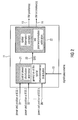
- Fig. 2 illustrates an apparatus for microphone positioning according to another embodiment.
- the apparatus comprises a spatial power distribution determiner 21 for determining a spatial power density (SPD), also referred to as spatial power distribution, indicating power values for a plurality of locations of an environment based on effective sound source information indicating one or more core values and position values of one or more effective sound sources allocated in the environment.
- the apparatus furthermore comprises a spatial information estimator 22 for estimating a position and/or orientation of a virtual microphone (VM) based on the spatial power density.
- SPD spatial power density
- VM virtual microphone
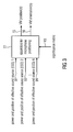
- Fig. 3 illustrates the inputs and outputs of an apparatus for microphone positioning according to an embodiment.
- the inputs 91, 92, ... 9N to the apparatus comprises the power, e.g., absolute value of the sound field pressure squared and position, e.g., 2D or 3D Cartesian coordinates.
- the effective sound sources (ESS) are describing the sound scene (sound field).
- the effective sound sources may, e.g., be equal to the instantaneous point-like sound sources (IPLS) as described below for the apparatus for generating an audio output signal of a virtual microphone at a configurable virtual position.
- IPLS instantaneous point-like sound sources
- the position and location of the one or more virtual microphones are returned.
- the term "physical source” is used to describe a real source from the sound scene, e.g., a talker
- ESS effective sound source
- ESS also referred to as “sound source”
- the term “sound source” is used to describe a sound event which is active in a single time or time-frequency bin, as also used for the IPLS described below with respect to the apparatus for generating an audio output signal of a virtual microphone at a configurable virtual position.
- sound source covers both physical sources as well as to effective sound sources.
- the input of the apparatus according to the embodiment of Fig. 2 , 91, 92, ..., 9N comprises information on the position and corresponding power of the plurality of N effective sound sources localized within a time instance or a time-frequency bin as described below for the apparatus for generating an audio output signal of a virtual microphone at a configurable virtual position, and as also described in [20] Giovanni Del Galdo, Oliver Thiergart, Tobias Weller, and E. A. P. Habets. Generating virtual microphone signals using geometrical information gathered by distributed arrays. In Third Joint Workshop on Hands-free Speech Communication and Microphone Arrays (HSCMA '11), Edinburgh, United Kingdom, May 2011.
- this information can be comprised in the output 106 in Fig. 14 of the information computation module of the apparatus for generating an audio output signal of a virtual microphone at a configurable virtual position considered below, for 1, 2, ..., N different frequency bins when a short-time Fourier transform (STFT) is applied.
- STFT short-time Fourier transform
- An apparatus for microphone positioning can be employed for a plurality of application scenarios:
- a single virtual microphone is positioned in the acoustic center of the sound scene.
- omnidirectional virtual microphones, cardioid virtual microphones, or a virtual spatial microphone is placed such that all participants are captured optimally ( Fig. 4b ).
- one spatial microphone is placed 'outside' the sound scene.
- a virtual stereo microphone is placed such that a broad spatial image is obtained, as illustrated in Fig. 4c .
- the optimal orientation of the virtual microphone is estimated while the virtual microphone is located at a fixed position (predetermined position), for example the position and directivity of the virtual microphone might be predefined and only the orientation is calculated automatically.
- a significant metric 13 which, for example, represents a measure of reliability for the estimation of the ESS positions.
- a metric can be derived from the variances of the direction of arrival estimators (when using two or more microphone arrays as explained) as explained below for the apparatus for generating an audio output signal of a virtual microphone at a configurable virtual position, or from the diffuseness parameter computed as in [21] Ville Pulkki. Spatial sound reproduction with directional audio coding. J. Audio Eng. Soc, 55(6):503-516, June 2007 .
- the metric can be expressed either with respect to all of the inputs 91, ..., 9N, (for example, a constant value of the metric for all inputs may be used), or, can be defined differently for each input 91, ..., 9N.
- the outputs 15, 16 of the apparatus of Fig. 2 may comprise the position and/or orientation of the one or more virtual microphones. Depending on the application, outputs (positions and orientations) for a plurality of virtual microphones may be generated, each corresponding to a specific virtual microphone.
- Fig. 5 illustrates a spatial power distribution determiner 21 according to an embodiment.
- the spatial power distribution determiner comprises a spatial power distribution main proccessing unit 31 and a spatial power distribution post processing unit 32.
- the spatial power distribution determiner 21 is adapted to determine (or rather compute) a modified spatial power density (SPD) denoted in the following by ⁇ (x, y, z, k, n), which expresses the power localized in a certain point, e.g., (x, y, z) in space for each time-frequency bin (k, n).
- the SPD is generated by integrating the power values at the positions of the effective sound sources 91, ..., 9N, which are input into the spatial power distribution determiner 21.
- the significance metric 103 ⁇ i represents an indicator of how reliable the position estimates of each effective sound source are. By default, the significance metric may be equal to 1.
- the SPD generated by the spatial power distribution main processing unit 31 may further be processed by the spatial power distribution main processing unit 32 (post processing of SPD and temporal integration module) and integrated in time, e.g., by employing an autoregressive filter.
- a post processing filter may, for example, be a low pass filter or a morphological (erosion, dilation) filter.
- an optional parameter which depends on the SPD may be employed. This parameter may refer to e.g., forbidden and/or preferred regions of the room where to place the virtual microphones (VM), or, may refer to the SPD, choosing specific SPD ranges, which satisfy some predetermined rules.
- ⁇ may be chosen such that it decreases for more unreliable estimates and increases for more reliable ones.
- ⁇ (x), ⁇ (y) and ⁇ (z) indicate delta functions (see Fig. 6a illustrating delta functions).
- s [ x y z ] T
- ⁇ [ ⁇ x ⁇ y ⁇ z ] T
- ⁇ ⁇ is the covariance matrix of the Gaussian distribution function g (see Fig. 6b illustrating distribution functions).
- function g can be described by a distribution function around the effective sound source positions given by the inputs 91 ... 9N, where e.g., the significance metric is the inverse of the variance of a Gaussian distribution. If the estimate of a sound source position has a high reliability, the according distribution will be rather narrow, whereas a more unreliable estimate would correspond to a high variants and would therefore, a wide distribution, see for example, Fig. 6b illustrating a 1D example.
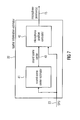
- Fig. 7 illustrates a spatial information estimator 22 according to an embodiment.
- the spatial information estimator comprises a sound scene center estimator 41 for estimating a position of a center of a sound scene in the environment. Furthermore, the spatial information estimator comprises a microphone position calculator 42 for calculating a position of a microphone as the acoustic spatial information based on the position of the center of the sound scene.
- Fig. 8 illustrates a spatial information estimator 22 according to a further embodiment.
- the spatial information estimator comprises a virtual microphone position calculator 44 being adapted to calculate an position of a virtual microphone and being further adapted to determine an orientation of a virtual microphone.
- the virtual microphone position calculator 44 is therefore also referred to as microphone position/orientation calculator 44.
- the spatial information estimator 22 of Fig. 8 uses as inputs the previously generated SPD 23. It returns as outputs the position 15 and orientation 16 of one or more virtual microphones, depending on the target application.
- the first processing block, the sound scene center estimator 41 provides an estimate of the sound scene center.
- the output 43 of block 41 e.g. the position of the sound scene center, is then provided as input to the second processing block, the virtual microphone position/orientation calculator 44.
- the virtual microphone position/orientation calculator 44 performs the actual estimation of the final position 15 and orientation 16 of one or more virtual microphones, depending on the target application.
- the sound scene center estimator 41 provides an estimate of the sound scene center.
- the output of the sound scene center estimator 41 is then provided as input to the microphone position/orientation calculator 44.
- the microphone position/orientation calculator 44 performs the actual estimation of the final position 15 and/or orientation 16 of the one or more virtual microphones according to the operating mode which characterizes the target application.
- the center of the sound scene is obtained by computing the center of gravity of the SPD ⁇ (x,y,z).
- the value of ⁇ (x,y,z) may be s interpreted as the existing mass at point (x,y,z) in space.
- the position in space with a minimum time dispersion of the channel shall be found. This is achieved by considering the root mean squared (RMS) delay spread.
- RMS root mean squared
- the position for which the mean delay ⁇ RMS, p is minimum will represent the center of the sound scene.
- a "circle-integration" is proposed.
- the radius r may either be constant or may vary depending on the power value in the point (x,y). For example, high power in the point (x,y) may correspond to a large radius, whereas low power may correspond to a small radius.
- Additional dependencies on the power may also be possible.
- One such example would be to convolve the circle with a bivariate Gaussian function before using it for constructing function g(x, y).
- the covariance matrix of the bivariate Gaussian function becomes dependent on the power in the position (x,y), i.e., high power corresponds to low variance, whereas low power corresponds to high variance.
- this concept is extended to 3D by employing a 3D convolution of ⁇ (x, y, z) with a sphere, analogously.
- Fig. 9 illustrates a microphone position/orientation calculator 44 according to another embodiment depicting more details.
- the center of the sound scene 43 is given as input to the microphone position/orientation calculator 44, together with the SPD 23.
- the information about the center of the sound scene 43 can be copied, depending on the operating required by the target application, to the output and used directly as the position of a virtual microphone, for example, when the application scenario of Fig. 4b is applicable, relating to the scenario with one virtual microphone positioned in the acoustic center of the sound scene.
- the information about the center of the sound scene 43 can be used as a modifying parameter inside the microphone position/orientation calculator 44.
- the optimization based on projected energy width defines a set of M equally spaced lines which pass through the center of the sound scene. For each of these lines, in e.g., a 2D scenario, the SPD F(x,y) is orthogonally projected on them and summed up.
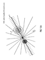
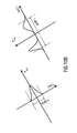
- Fig. 10a - 10c illustrate optimization based on projected energy width.
- the projected power function P proj is computed for each of the l1, ⁇ ⁇ ⁇ li, ⁇ ⁇ ⁇ lM lines.
- the corresponding widths of the function are then calculated, see Fig. 10b .
- the width may be defined as a -3 dB width, which is equivalent to the distance for which the leftmost and rightmost points of the distance segment corresponds to a predefined power level, for example, a power level higher than -3 dB.
- the line with the broadest width is identified and the virtual microphone is placed on the orthogonal direction to it.
- the orientation of the virtual microphone may be set such that it points to the center of the sound scene, as explained in the next section.
- two possible virtual microphone (VM) positions are obtained, since the VM can be positioned either on the positive or on the negative orthogonal direction.
- the distance at which the VM is positioned may be computed, for example, based on geometric considerations together with the opening angle of the virtual microphone. This is illustrated by Fig. 510.
- the distance at which the VM is positioned varies depending on the operating mode specific to the target application. This implies constructing a triangle such that the width i of Fig. 10c represents one side of the triangle and the center of gravity COG is the midpoint of the side. By taking the orthogonal line at the COG and defining it as the bisector of the VM opening angle ⁇ , the third vertex of the triangle is found. The length of the bisector then gives the distance between the VM position and the center of the sound scene.
- the described optimization concept based on projected energy may be extended to 3D.
- M 2 equally spaced planes (in azimuthal and elevation direction) are defined instead of M lines.
- the width then corresponds to the diameter of the circle which comprises the largest part of the projected energy.
- the final position is obtained by placing the VM on the normal to the plane surface of the largest circle diameter.
- the distance from the center of the sound scene to the VM position may be computed again, similarly as in the 2D case, that is using geometric considerations and the opening angle specified by the operating mode.
- optimization based on a principle component analysis uses directly the information available from the SPD.
- the SPD ⁇ (x,y,z) is quantized and a threshold-selective filter is applied on the quantized data set. By this, all points which have energy levels smaller than a certain threshold are discarded.
- the first column of U represents the principal component, which has the highest variability of the data set.
- the second column of U is orthogonal to the first and represents the direction on which we want to place the VM.
- the width is implicitly given by the first singular value in the matrix E. Knowing the width, as well as the direction, we can compute the position and orientation of the VM as described in the optimization method based on projected energy width as described above explained with reference to Fig. 10a - 10c .
- these methods are applied to a 2D problem, which is straightforward, as one merely needs to ignore/remove the z axis component from the equations and considerations.
- a different concept may be employed, such as an iterative optimization scheme.
- a first step the position with the maximum value of the SPD is identified. By this, the location of the first VM of the total of N virtual microphones is designated. Following this, all energy surrounding this position (i.e., up to a certain distance) is removed from the SPD. The previous steps are repeated until all the positions of the N virtual microphones are found. In the case where N is not defined, the iteration is performed unit the maximum value is the SPD becomes smaller than a certain threshold.
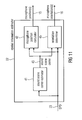
- Fig. 11 illustrates another embodiment, wherein a spatial information estimator 22 furthermore comprises an orientation determiner 45.
- the orientation determiner 45 is adapted to determine a (suitable) orientation 16 of the microphone based on the spectral power density 23.
- orientation estimation will be described.
- the optimization approaches based on projected energy width as well as on principal component analysis compute the orientation of the virtual microphone 15 implicitly, since the virtual microphone is assumed to be oriented towards the center of the sound scene.
- the orientation should be determined, such that the virtual microphone picks up most of the energy in the sound scene.
- ⁇ ⁇ 0 r max ⁇ r cos ⁇ , r sin ⁇ ⁇ r d ⁇ r , where r max is defined is defined as the maximum distance from the VM and controls the VM's pick-up pattern.
- ⁇ ⁇ arg max ⁇ ⁇ - ⁇ ⁇ f ⁇ ⁇ w ⁇ ⁇ ⁇ d ⁇ ⁇ ⁇ , where ⁇ ⁇ ( ⁇ ) is a weighting function based on the input characteristics of the VM.
- ⁇ ⁇ ( ⁇ ) may be the function which defines how the energy coming from direction ⁇ is scaled given a certain viewing direction ⁇ and a specific pick-up pattern of the VM.
- an apparatus for generating an audio output signal to simulate a recording of a virtual microphone at a configurable virtual position in an environment is explained.
- An apparatus for microphone positioning according to one of the above described embodiments may be employed to determine the virtual position for the apparatus for generating the audio output signal.
- Fig. 12 illustrates an apparatus for generating an audio output signal to simulate a recording of a virtual microphone at a configurable virtual position posVmic in an environment.
- the apparatus comprises a sound events position estimator 110 and an information computation module 120.
- the sound events position estimator 110 receives a first direction information di1 from a first real spatial microphone and a second direction information di2 from a second real spatial microphone.
- the sound events position estimator 110 is adapted to estimate a sound source position ssp indicating a position of a sound source in the environment, the sound source emitting a sound wave, wherein the sound events position estimator 110 is adapted to estimate the sound source position ssp based on a first direction information di1 provided by a first real spatial microphone being located at a first real microphone position pos1mic in the environment, and based on a second direction information di2 provided by a second real spatial microphone being located at a second real microphone position in the environment.
- the information computation module 120 is adapted to generate the audio output signal based on a first recorded audio input signal is1 being recorded by the first real spatial microphone, based on the first real microphone position pos1mic and based on the virtual position posVmic of the virtual microphone.
- the information computation module 120 comprises a propagation compensator being adapted to generate a first modified audio signal by modifying the first recorded audio input signal isl by compensating a first delay or amplitude decay between an arrival of the sound wave emitted by the sound source at the first real spatial microphone and an arrival of the sound wave at the virtual microphone by adjusting an amplitude value, a magnitude value or a phase value of the first recorded audio input signal is1, to obtain the audio output signal.
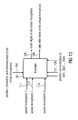
- Fig. 13 illustrates the inputs and outputs of an apparatus and a method according to an embodiment.
- Information from two or more real spatial microphones 111, 112, ..., 11N is fed to the apparatus/is processed by the method.
- This information comprises audio signals picked up by the real spatial microphones as well as direction information from the real spatial microphones, e.g. direction of arrival (DOA) estimates.
- the audio signals and the direction information, such as the direction of arrival estimates may be expressed in a time-frequency domain. If, for example, a 2D geometry reconstruction is desired and a traditional STFT (short time Fourier transformation) domain is chosen for the representation of the signals, the DOA may be expressed as azimuth angles dependent on k and n, namely the frequency and time indices.
- DOA short time Fourier transformation
- the sound event localization in space, as well as describing the position of the virtual microphone may be conducted based on the positions and orientations of the real and virtual spatial microphones in a common coordinate system.
- This information may be represented by the inputs 121 ... 12N and input 104 in Fig. 13 .
- the input 104 may additionally specify the characteristic of the virtual spatial microphone, e.g., its position and pick-up pattern, as will be discussed in the following. If the virtual spatial microphone comprises multiple virtual sensors, their positions and the corresponding different pick-up patterns may be considered.
- the output of the apparatus or a corresponding method may be, when desired, one or more sound signals 105, which may have been picked up by a spatial microphone defined and placed as specified by 104. Moreover, the apparatus (or rather the method) may provide as output corresponding spatial side information 106 which may be estimated by employing the virtual spatial microphone.
- Fig. 14 illustrates an apparatus according to an embodiment, which comprises two main processing units, a sound events position estimator 201 and an information computation module 202.
- the sound events position estimator 201 may carry out geometrical reconstruction on the basis of the DOAs comprised in inputs 111 ... 11N and based on the knowledge of the position and orientation of the real spatial microphones, where the DOAs have been computed.
- the output of the sound events position estimator 205 comprises the position estimates (either in 2D or 3D) of the sound sources where the sound events occur for each time and frequency bin.
- the second processing block 202 is an information computation module. According to the embodiment of Fig. 14 , the second processing block 202 computes a virtual microphone signal and spatial side information.
- virtual microphone signal and side information computation block 202 uses the sound events' positions 205 to process the audio signals comprised in 111...11N to output the virtual microphone audio signal 105.
- Block 202 may also compute the spatial side information 106 corresponding to the virtual spatial microphone. Embodiments below illustrate possibilities, how blocks 201 and 202 may operate.
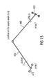
- Fig. 15 shows an exemplary scenario in which the real spatial microphones are depicted as Uniform Linear Arrays (ULAs) of 3 microphones each.
- the DOA expressed as the azimuth angles al(k, n) and a2(k, n), are computed for the time-frequency bin (k, n). This is achieved by employing a proper DOA estimator, such as ESPRIT, [13] R. Roy, A. Paulraj, and T.
- Fig. 15 two real spatial microphones, here, two real spatial microphone arrays 410, 420 are illustrated.
- the two estimated DOAs al(k, n) and a2(k, n) are represented by two lines, a first line 430 representing DOA al(k, n) and a second line 440 representing DOA a2(k, n).
- the triangulation is possible via simple geometrical considerations knowing the position and orientation of each array.
- the triangulation fails when the two lines 430, 440 are exactly parallel. In real applications, however, this is very unlikely. However, not all triangulation results correspond to a physical or feasible position for the sound event in the considered space. For example, the estimated position of the sound event might be too far away or even outside the assumed space, indicating that probably the DOAs do not correspond to any sound event which can be physically interpreted with the used model. Such results may be caused by sensor noise or too strong room reverberation. Therefore, according to an embodiment, such undesired results are flagged such that the information computation module 202 can treat them properly.
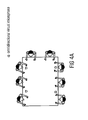
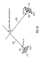
- Fig. 16 depicts a scenario, where the position of a sound event is estimated in 3D space.
- Proper spatial microphones are employed, for example, a planar or 3D microphone array.
- a first spatial microphone 510 for example, a first 3D microphone array
- a second spatial microphone 520 e.g. , a first 3D microphone array
- the DOA in the 3D space may for example, be expressed as azimuth and elevation.
- Unit vectors 530, 540 may be employed to express the DOAs.
- Two lines 550, 560 are projected according to the DOAs. In 3D, even with very reliable estimates, the two lines 550, 560 projected according to the DOAs might not intersect. However, the triangulation can still be carried out, for example, by choosing the middle point of the smallest segment connecting the two lines.
- the triangulation may fail or may yield unfeasible results for certain combinations of directions, which may then also be flagged, e.g. to the information computation module 202 of Fig. 14 .
- the sound field may be analyzed in the time-frequency domain, for example, obtained via a short-time Fourier transform (STFT), in which k and n denote the frequency index k and time index n, respectively.
- STFT short-time Fourier transform
- the complex pressure P v (k, n) at an arbitrary position p v for a certain k and n is modeled as a single spherical wave emitted by a narrow-band isotropic point-like source, e.g.
- P ⁇ k ⁇ n P IPLS k ⁇ n ⁇ ⁇ k , p IPLS k ⁇ n , p ⁇ , where P IPLS (k, n) is the signal emitted by the IPLS at its position p IPLS (k, n).
- the complex factor ⁇ (k, p IPLS , p v ) expresses the propagation from p IPLS (k, n) to p v , e.g., it introduces appropriate phase and magnitude modifications.
- the assumption may be applied that in each time-frequency bin only one IPLS is active. Nevertheless, multiple narrow-band IPLSs located at different positions may also be active at a single time instance.
- Each IPLS either models direct sound or a distinct room reflection. Its position p IPLS (k, n) may ideally correspond to an actual sound source located inside the room, or a mirror image sound source located outside, respectively. Therefore, the position p IPLS (k, n) may also indicates the position of a sound event.
- real sound sources denotes the actual sound sources physically existing in the recording environment, such as talkers or musical instruments.
- sound sources or “sound events” or “IPLS” we refer to effective sound sources, which are active at certain time instants or at certain time-frequency bins, wherein the sound sources may, for example, represent real sound sources or mirror image sources.
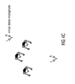
- Fig. 27a-27b illustrate microphone arrays localizing sound sources.
- the localized sound sources may have different physical interpretations depending on their nature. When the microphone arrays receive direct sound, they may be able to localize the position of a true sound source (e.g. talkers). When the microphone arrays receive reflections, they may localize the position of a mirror image source. Mirror image sources are also sound sources.
- Fig. 27a illustrates a scenario, where two microphone arrays 151 and 152 receive direct sound from an actual sound source (a physically existing sound source) 153.
- Fig. 27b illustrates a scenario, where two microphone arrays 161, 162 receive reflected sound, wherein the sound has been reflected by a wall. Because of the reflection, the microphone arrays 161, 162 localize the position, where the sound appears to come from, at a position of an mirror image source 165, which is different from the position of the speaker 163.
- Both the actual sound source 153 of Fig. 27a , as well as the mirror image source 165 are sound sources.
- Fig. 27c illustrates a scenario, where two microphone arrays 171, 172 receive diffuse sound and are not able to localize a sound source.
- the model also provides a good estimate for other environments and is therefore also applicable for those environments.
- the position p IPLS (k, n) of an active IPLS in a certain time-frequency bin is estimated via triangulation on the basis of the direction of arrival (DOA) of sound measured in at least two different observation points.
- DOA direction of arrival
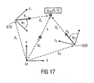
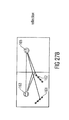
- Fig. 17 illustrates a geometry, where the IPLS of the current time-frequency slot (k, n) is located in the unknown position p IPLS (k, n).
- two real spatial microphones here, two microphone arrays, are employed having a known geometry, position and orientation, which are placed in positions 610 and 620, respectively.
- the vectors p 1 and p 2 point to the positions 610, 620, respectively.
- the array orientations are defined by the unit vectors c 1 and c 2 .
- the DOA of the sound is determined in the positions 610 and 620 for each (k, n) using a DOA estimation algorithm, for instance as provided by the DirAC analysis (see [2], [3]).
- a first point-of-view unit vector e 1 POV k ⁇ n and a second point-of-view unit vector e 2 POV k ⁇ n with respect to a point of view of the microphone arrays may be provided as output of the DirAC analysis.
- ⁇ 1 (k, n) represents the azimuth of the DOA estimated at the first microphone array, as depicted in Fig. 17 .
- equation (6) may be solved for d 2 (k, n) and p IPLS (k, n) is analogously computed employing d 2 (k, n).
- Equation (6) always provides a solution when operating in 2D, unless e 1 (k, n) and e 2 (k, n) are parallel. However, when using more than two microphone arrays or when operating in 3D, a solution cannot be obtained when the direction vectors d do not intersect. According to an embodiment, in this case, the point which is closest to all direction vectors d is be computed and the result can be used as the position of the IPLS.
- all observation points p 1 , p 2 , ... should be located such that the sound emitted by the IPLS falls into the same temporal block n.
- an information computation module 202 e.g. a virtual microphone signal and side information computation module, according to an embodiment is described in more detail.
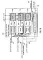
- Fig. 18 illustrates a schematic overview of an information computation module 202 according to an embodiment.
- the information computation unit comprises a propagation compensator 500, a combiner 510 and a spectral weighting unit 520.
- the information computation module 202 receives the sound source position estimates ssp estimated by a sound events position estimator, one or more audio input signals is recorded by one or more of the real spatial microphones, positions posRealMic of one or more of the real spatial microphones, and the virtual position posVmic of the virtual microphone. It outputs an audio output signal os representing an audio signal of the virtual microphone.
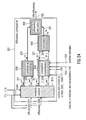
- Fig. 19 illustrates an information computation module according to another embodiment.
- the information computation module of Fig. 19 comprises a propagation compensator 500, a combiner 510 and a spectral weighting unit 520.
- the propagation compensator 500 comprises a propagation parameters computation module 501 and a propagation compensation module 504.
- the combiner 510 comprises a combination factors computation module 502 and a combination module 505.
- the spectral weighting unit 520 comprises a spectral weights computation unit 503, a spectral weighting application module 506 and a spatial side information computation module 507.
- the geometrical information e.g. the position and orientation of the real spatial microphones 121 ... 12N, the position, orientation and characteristics of the virtual spatial microphone 104, and the position estimates of the sound events 205 are fed into the information computation module 202, in particular, into the propagation parameters computation module 501 of the propagation compensator 500, into the combination factors computation module 502 of the combiner 510 and into the spectral weights computation unit 503 of the spectral weighting unit 520.
- the propagation parameters computation module 501, the combination factors computation module 502 and the spectral weights computation unit 503 compute the parameters used in the modification of the audio signals 111 ... 11N in the propagation compensation module 504, the combination module 505 and the spectral weighting application module 506.
- the audio signals 111 ... 11N may at first be modified to compensate for the effects given by the different propagation lengths between the sound event positions and the real spatial microphones.
- the signals may then be combined to improve for instance the signal-to-noise ratio (SNR).
- SNR signal-to-noise ratio
- the resulting signal may then be spectrally weighted to take the directional pick up pattern of the virtual microphone into account, as well as any distance dependent gain function.
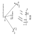
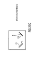
- Fig. 20 two real spatial microphones (a first microphone array 910 and a second microphone array 920), the position of a localized sound event 930 for time-frequency bin (k, n), and the position of the virtual spatial microphone 940 are illustrated.
- Fig. 20 depicts a temporal axis. It is assumed that a sound event is emitted at time t0 and then propagates to the real and virtual spatial microphones. The time delays of arrival as well as the amplitudes change with distance, so that the further the propagation length, the weaker the amplitude and the longer the time delay of arrival are.
- the signals at the two real arrays are comparable only if the relative delay Dt12 between them is small. Otherwise, one of the two signals needs to be temporally realigned to compensate the relative delay Dt12, and possibly, to be scaled to compensate for the different decays.
- Compensating the delay between the arrival at the virtual microphone and the arrival at the real microphone arrays (at one of the real spatial microphones) changes the delay independent from the localization of the sound event, making it superfluous for most applications.
- propagation parameters computation module 501 is adapted to compute the delays to be corrected for each real spatial microphone and for each sound event. If desired, it also computes the gain factors to be considered to compensate for the different amplitude decays.
- the propagation compensation module 504 is configured to use this information to modify the audio signals accordingly. If the signals are to be shifted by a small amount of time (compared to the time window of the filter bank), then a simple phase rotation suffices. If the delays are larger, more complicated implementations are necessary.
- the output of the propagation compensation module 504 are the modified audio signals expressed in the original time-frequency domain.
- Fig. 17 which inter alia illustrates the position 610 of a first real spatial microphone and the position 620 of a second real spatial microphone.
- a first recorded audio input signal e.g. a pressure signal of at least one of the real spatial microphones (e.g. the microphone arrays) is available, for example, the pressure signal of a first real spatial microphone.
- a first recorded audio input signal e.g. a pressure signal of at least one of the real spatial microphones (e.g. the microphone arrays)
- the pressure signal of a first real spatial microphone we will refer to the considered microphone as reference microphone, to its position as reference position p ref and to its pressure signal as reference pressure signal P ref (k, n).
- propagation compensation may not only be conducted with respect to only one pressure signal, but also with respect to the pressure signals of a plurality or of all of the real spatial microphones.
- the complex factor ⁇ (k, p a , p b ) expresses the phase rotation and amplitude decay introduced by the propagation of a spherical wave from its origin in p a to p b .
- the sound energy which can be measured in a certain point in space depends strongly on the distance r from the sound source, in Fig 6 from the position p IPLS of the sound source. In many situations, this dependency can be modeled with sufficient accuracy using well-known physical principles, for example, the 1/r decay of the sound pressure in the far-field of a point source.
- the distance of a reference microphone for example, the first real microphone from the sound source is known, and when also the distance of the virtual microphone from the sound source is known, then, the sound energy at the position of the virtual microphone can be estimated from the signal and the energy of the reference microphone, e.g. the first real spatial microphone. This means, that the output signal of the virtual microphone can be obtained by applying proper gains to the reference pressure signal.
- formula (12) can accurately reconstruct the magnitude information.
- the presented method yields an implicit dereverberation of the signal when moving the virtual microphone away from the positions of the sensor arrays.
- the magnitude of the reference pressure is decreased when applying a weighting according to formula (11).
- the time-frequency bins corresponding to the direct sound will be amplified such that the overall audio signal will be perceived less diffuse.
- the rule in formula (12) one can control the direct sound amplification and diffuse sound suppression at will.
- a first modified audio signal is obtained.
- a second modified audio signal may be obtained by conducting propagation compensation on a recorded second audio input signal (second pressure signal) of the second real spatial microphone.
- further audio signals may be obtained by conducting propagation compensation on recorded further audio input signals (further pressure signals) of further real spatial microphones.
- module 502 The task of module 502 is, if applicable, to compute parameters for the combining, which is carried out in module 505.
- the audio signal resulting from the combination or from the propagation compensation of the input audio signals is weighted in the time-frequency domain according to spatial characteristics of the virtual spatial microphone as specified by input 104 and/or according to the reconstructed geometry (given in 205).
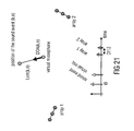
- the geometrical reconstruction allows us to easily obtain the DOA relative to the virtual microphone, as shown in Fig. 21 . Furthermore, the distance between the virtual microphone and the position of the sound event can also be readily computed.
- the weight for the time-frequency bin is then computed considering the type of virtual microphone desired.
- the spectral weights may be computed according to a predefined pick-up pattern.
- Another possibility is artistic (non physical) decay functions.
- some embodiments introduce an additional weighting function which depends on the distance between the virtual microphone and the sound event. In an embodiment, only sound events within a certain distance (e.g. in meters) from the virtual microphone should be picked up.
- arbitrary directivity patterns can be applied for the virtual microphone. In doing so, one can for instance separate a source from a complex sound scene.
- one or more real, non-spatial microphones are placed in the sound scene in addition to the real spatial microphones to further improve the sound quality of the virtual microphone signals 105 in Figure 8 .
- These microphones are not used to gather any geometrical information, but rather only to provide a cleaner audio signal. These microphones may be placed closer to the sound sources than the spatial microphones.
- the audio signals of the real, non-spatial microphones and their positions are simply fed to the propagation compensation module 504 of Fig. 19 for processing, instead of the audio signals of the real spatial microphones. Propagation compensation is then conducted for the one or more recorded audio signals of the non-spatial microphones with respect to the position of the one or more non-spatial microphones.
- the information computation module 202 of Fig. 19 comprises a spatial side information computation module 507, which is adapted to receive as input the sound sources' positions 205 and the position, orientation and characteristics 104 of the virtual microphone.
- the audio signal of the virtual microphone 105 can also be taken into account as input to the spatial side information computation module 507.
- the output of the spatial side information computation module 507 is the side information of the virtual microphone 106.
- This side information can be, for instance, the DOA or the diffuseness of sound for each time-frequency bin (k, n) from the point of view of the virtual microphone.
- Another possible side information could, for instance, be the active sound intensity vector Ia(k, n) which would have been measured in the position of the virtual microphone. How these parameters can be derived, will now be described.
- DOA estimation for the virtual spatial microphone is realized.
- the information computation module 120 is adapted to estimate the direction of arrival at the virtual microphone as spatial side information, based on a position vector of the virtual microphone and based on a position vector of the sound event as illustrated by Fig. 22 .
- Fig. 22 depicts a possible way to derive the DOA of the sound from the point of view of the virtual microphone.
- the position of the sound event provided by block 205 in Fig. 19 , can be described for each time-frequency bin (k, n) with a position vector r(k, n), the position vector of the sound event.
- the position of the virtual microphone provided as input 104 in Fig. 19 , can be described with a position vector s(k,n), the position vector of the virtual microphone.
- the look direction of the virtual microphone can be described by a vector v(k, n).
- the DOA relative to the virtual microphone is given by a(k,n). It represents the angle between v and the sound propagation path h (k,n).
- the information computation module 120 may be adapted to estimate the active sound intensity at the virtual microphone as spatial side information, based on a position vector of the virtual microphone and based on a position vector of the sound event as illustrated by Fig. 22 .
- the active sound intensity Ia (k, n) at the position of the virtual microphone.
- the virtual microphone audio signal 105 in Fig. 19 corresponds to the output of an omnidirectional microphone, e.g., we assume, that the virtual microphone is an omnidirectional microphone.
- the looking direction v in Fig. 22 is assumed to be parallel to the x-axis of the coordinate system. Since the desired active sound intensity vector Ia (k, n) describes the net flow of energy through the position of the virtual microphone, we can compute Ia (k, n) can be computed, e.g.
- Ia k ⁇ n - 1 / 2 rho ⁇ P v k ⁇ n 2 * cos a k ⁇ n , sin a k ⁇ n T , where [] T denotes a transposed vector, rho is the air density, and P v (k, n) is the sound pressure measured by the virtual spatial microphone, e.g., the output 105 of block 506 in Fig. 19 .
- Ia k ⁇ n 1 / 2 rho P v k ⁇ n 2 h k ⁇ n / ⁇ h k ⁇ n ⁇ .
- the diffuseness of sound expresses how diffuse the sound field is in a given time-frequency slot (see, for example, [2]). Diffuseness is expressed by a value ⁇ , wherein 0 ⁇ ⁇ ⁇ 1. A diffuseness of 1 indicates that the total sound field energy of a sound field is completely diffuse. This information is important e.g. in the reproduction of spatial sound. Traditionally, diffuseness is computed at the specific point in space in which a microphone array is placed.
- the diffuseness may be computed as an additional parameter to the side information generated for the Virtual Microphone (VM), which can be placed at will at an arbitrary position in the sound scene.
- VM Virtual Microphone
- an apparatus that also calculates the diffuseness besides the audio signal at a virtual position of a virtual microphone can be seen as a virtual DirAC front-end, as it is possible to produce a DirAC stream, namely an audio signal, direction of arrival, and diffuseness, for an arbitrary point in the sound scene.
- the DirAC stream may be further processed, stored, transmitted, and played back on an arbitrary multi-loudspeaker setup. In this case, the listener experiences the sound scene as if he or she were in the position specified by the virtual microphone and were looking in the direction determined by its orientation.
- Fig. 23 illustrates an information computation block according to an embodiment comprising a diffuseness computation unit 801 for computing the diffuseness at the virtual microphone.
- the information computation block 202 is adapted to receive inputs 111 to 11N, that in addition to the inputs of Fig. 14 also include diffuseness at the real spatial microphones. Let ⁇ (SM1) to ⁇ (SMN) denote these values. These additional inputs are fed to the information computation module 202.
- the output 103 of the diffuseness computation unit 801 is the diffuseness parameter computed at the position of the virtual microphone.
- a diffuseness computation unit 801 of an embodiment is illustrated in Fig. 24 depicting more details.
- the energy of direct and diffuse sound at each of the N spatial microphones is estimated.
- N estimates of these energies at the position of the virtual microphone are obtained.
- the estimates can be combined to improve the estimation accuracy and the diffuseness parameter at the virtual microphone can be readily computed.
- a more effective combination of the estimates E diff SM 1 to E diff SM N could be carried out by considering the variance of the estimators, for instance, by considering the SNR.
- the estimates of the direct sound energy obtained at different spatial microphones can be combined, e.g. by a direct sound combination unit 840.
- the result is E dir VM , e.g., the estimate for the direct sound energy at the virtual microphone.
- the sound events position estimation carried out by a sound events position estimator fails, e.g., in case of a wrong direction of arrival estimation.
- Fig. 25 illustrates such a scenario.
- the diffuseness for the virtual microphone 103 may be set to 1 (i.e., fully diffuse), as no spatially coherent reproduction is possible.
- the reliability of the DOA estimates at the N spatial microphones may be considered. This may be expressed e.g. in terms of the variance of the DOA estimator or SNR. Such an information may be taken into account by the diffuseness sub-calculator 850, so that the VM diffuseness 103 can be artificially increased in case that the DOA estimates are unreliable. In fact, as a consequence, the position estimates 205 will also be unreliable.
- Fig. 26 illustrates an apparatus 991 for generating a virtual output signal according to an embodiment.
- the apparatus 991 for generating a virtual output signal comprises an apparatus 992 for microphone positioning according to one of the above-described embodiments which comprises a microphone position calculator 993.
- the apparatus for generating a virtual output signal comprises an apparatus 994 for generating an audio output signal according to one of the above-described embodiments.
- the output signal generated by the apparatus 994 for generating an audio output signal is the virtual output signal vos.
- the microphone position calculator 992 of the apparatus for microphone positioning 991 is configured to calculate the position of a microphone as a calculated microphone position cmp.
- the apparatus 994 for generating an audio output signal is configured to simulate a recording of a virtual microphone at the calculated microphone position calculated by the apparatus 992 for microphone positioning. By this, the apparatus 992 for microphone positioning calculates the virtual position of the virtual microphone for the apparatus 994 for generating an audio output signal.
- aspects have been described in the context of an apparatus, it is clear that these aspects also represent a description of the corresponding method, where a block or device corresponds to a method step or a feature of a method step. Analogously, aspects described in the context of a method step also represent a description of a corresponding block or item or feature of a corresponding apparatus.
- the inventive decomposed signal can be stored on a digital storage medium or can be transmitted on a transmission medium such as a wireless transmission medium or a wired transmission medium such as the Internet.
- embodiments of the invention can be implemented in hardware or in software.
- the implementation can be performed using a digital storage medium, for example a floppy disk, a DVD, a CD, a ROM, a PROM, an EPROM, an EEPROM or a FLASH memory, having electronically readable control signals stored thereon, which cooperate (or are capable of cooperating) with a programmable computer system such that the respective method is performed.
- a digital storage medium for example a floppy disk, a DVD, a CD, a ROM, a PROM, an EPROM, an EEPROM or a FLASH memory, having electronically readable control signals stored thereon, which cooperate (or are capable of cooperating) with a programmable computer system such that the respective method is performed.
- Some embodiments according to the invention comprise a non-transitory data carrier having electronically readable control signals, which are capable of cooperating with a programmable computer system, such that one of the methods described herein is performed.
- embodiments of the present invention can be implemented as a computer program product with a program code, the program code being operative for performing one of the methods when the computer program product runs on a computer.
- the program code may for example be stored on a machine readable carrier.
- inventions comprise the computer program for performing one of the methods described herein, stored on a machine readable carrier.
- an embodiment of the inventive method is, therefore, a computer program having a program code for performing one of the methods described herein, when the computer program runs on a computer.
- a further embodiment of the inventive methods is, therefore, a data carrier (or a digital storage medium, or a computer-readable medium) comprising, recorded thereon, the computer program for performing one of the methods described herein.
- a further embodiment of the inventive method is, therefore, a data stream or a sequence of signals representing the computer program for performing one of the methods described herein.
- the data stream or the sequence of signals may for example be configured to be transferred via a data communication connection, for example via the Internet.
- a further embodiment comprises a processing means, for example a computer, or a programmable logic device, configured to or adapted to perform one of the methods described herein.
- a processing means for example a computer, or a programmable logic device, configured to or adapted to perform one of the methods described herein.
- a further embodiment comprises a computer having installed thereon the computer program for performing one of the methods described herein.
- a programmable logic device for example a field programmable gate array
- a field programmable gate array may cooperate with a microprocessor in order to perform one of the methods described herein.
- the methods are preferably performed by any hardware apparatus.
Priority Applications (22)
| Application Number | Priority Date | Filing Date | Title |
|---|---|---|---|
| EP11191828.0A EP2600637A1 (fr) | 2011-12-02 | 2011-12-02 | Appareil et procédé pour le positionnement de microphone en fonction de la densité spatiale de puissance |
| US13/445,560 US10284947B2 (en) | 2011-12-02 | 2012-04-12 | Apparatus and method for microphone positioning based on a spatial power density |
| PT127949428T PT2786593E (pt) | 2011-12-02 | 2012-11-29 | Aparelho e método para o posicionamento de microfone com base numa densidade de potência espacial |
| EP12794942.8A EP2786593B1 (fr) | 2011-12-02 | 2012-11-29 | Appareil et procédé pour le positionnement de microphone en fonction de la densité spatiale de puissance |
| AU2012343907A AU2012343907B2 (en) | 2011-12-02 | 2012-11-29 | Apparatus and method for microphone positioning based on a spatial power density |
| MX2014006499A MX338524B (es) | 2011-12-02 | 2012-11-29 | Aparato y metodo para posicionar microfonos basado en la densidad de potencia espacial. |
| BR112014013335-2A BR112014013335B1 (pt) | 2012-04-12 | 2012-11-29 | Aparelho e método para posicionamento de microfone com base em uma densidade de potência espacial |
| PL12794942.8T PL2786593T3 (pl) | 2011-12-02 | 2012-11-29 | Urządzenie i sposób do pozycjonowania mikrofonu w oparciu o gęstość przestrzenną mocy |
| PCT/EP2012/073906 WO2013079568A1 (fr) | 2011-12-02 | 2012-11-29 | Appareil et procédé de positionnement de microphone basé sur une densité d'énergie spatiale |
| ES12794942.8T ES2573802T3 (es) | 2011-12-02 | 2012-11-29 | Aparato y método para colocar micrófonos basándose en una densidad de potencia espacial |
| CA2857611A CA2857611C (fr) | 2011-12-02 | 2012-11-29 | Appareil et procede de positionnement de microphone base sur une densite d'energie spatiale |
| KR1020147018347A KR101591220B1 (ko) | 2011-12-02 | 2012-11-29 | 공간적 전력 밀도에 기초하여 마이크 위치 결정을 위한 장치 및 방법 |
| CN201280067394.1A CN104094613B (zh) | 2011-12-02 | 2012-11-29 | 用于依据空间功率密度定位麦克风的装置和方法 |
| SG11201402782VA SG11201402782VA (en) | 2011-12-02 | 2012-11-29 | Apparatus and method for microphone positioning based on a spatial power density |
| MYPI2014001579A MY167624A (en) | 2011-12-02 | 2012-11-29 | Apparatus and method for microphone positioning based on a spatial power density |
| RU2014126819/28A RU2589469C2 (ru) | 2011-12-02 | 2012-11-29 | Устройство и способ для позиционирования микрофона, основываясь на пространственной плотности мощности |
| IN1144KON2014 IN2014KN01144A (fr) | 2011-12-02 | 2012-11-29 | |
| JP2014543883A JP5814476B2 (ja) | 2011-12-02 | 2012-11-29 | 空間パワー密度に基づくマイクロフォン位置決め装置および方法 |
| ARP120104512A AR089052A1 (es) | 2011-12-02 | 2012-11-30 | Aparato y metodo para posicionar microfonos basado en la densidad de potencia espacial |
| TW101145071A TWI558228B (zh) | 2011-12-02 | 2012-11-30 | 依據空間能量密度定位麥克風之設備及方法 |
| ZA2014/04822A ZA201404822B (en) | 2011-12-02 | 2014-06-30 | Apparatus and method for microphone positioning based on a spatial power density |
| HK15102681.3A HK1202746A1 (zh) | 2011-12-02 | 2015-03-16 | 用於依據空間功率密度定位麥克風的裝置和方法 |
Applications Claiming Priority (1)
| Application Number | Priority Date | Filing Date | Title |
|---|---|---|---|
| EP11191828.0A EP2600637A1 (fr) | 2011-12-02 | 2011-12-02 | Appareil et procédé pour le positionnement de microphone en fonction de la densité spatiale de puissance |
Publications (1)
| Publication Number | Publication Date |
|---|---|
| EP2600637A1 true EP2600637A1 (fr) | 2013-06-05 |
Family
ID=45218364
Family Applications (2)
| Application Number | Title | Priority Date | Filing Date |
|---|---|---|---|
| EP11191828.0A Withdrawn EP2600637A1 (fr) | 2011-12-02 | 2011-12-02 | Appareil et procédé pour le positionnement de microphone en fonction de la densité spatiale de puissance |
| EP12794942.8A Active EP2786593B1 (fr) | 2011-12-02 | 2012-11-29 | Appareil et procédé pour le positionnement de microphone en fonction de la densité spatiale de puissance |
Family Applications After (1)
| Application Number | Title | Priority Date | Filing Date |
|---|---|---|---|
| EP12794942.8A Active EP2786593B1 (fr) | 2011-12-02 | 2012-11-29 | Appareil et procédé pour le positionnement de microphone en fonction de la densité spatiale de puissance |
Country Status (20)
| Country | Link |
|---|---|
| US (1) | US10284947B2 (fr) |
| EP (2) | EP2600637A1 (fr) |
| JP (1) | JP5814476B2 (fr) |
| KR (1) | KR101591220B1 (fr) |
| CN (1) | CN104094613B (fr) |
| AR (1) | AR089052A1 (fr) |
| AU (1) | AU2012343907B2 (fr) |
| CA (1) | CA2857611C (fr) |
| ES (1) | ES2573802T3 (fr) |
| HK (1) | HK1202746A1 (fr) |
| IN (1) | IN2014KN01144A (fr) |
| MX (1) | MX338524B (fr) |
| MY (1) | MY167624A (fr) |
| PL (1) | PL2786593T3 (fr) |
| PT (1) | PT2786593E (fr) |
| RU (1) | RU2589469C2 (fr) |
| SG (1) | SG11201402782VA (fr) |
| TW (1) | TWI558228B (fr) |
| WO (1) | WO2013079568A1 (fr) |
| ZA (1) | ZA201404822B (fr) |
Cited By (3)
| Publication number | Priority date | Publication date | Assignee | Title |
|---|---|---|---|---|
| CN104794894A (zh) * | 2015-01-29 | 2015-07-22 | 青岛智能产业技术研究院 | 一种汽车鸣笛噪声监视装置、系统及方法 |
| EP3070876A1 (fr) | 2015-03-17 | 2016-09-21 | Telefonica Digital España, S.L.U. | Procédé et système permettant d'améliorer des services de téléconférence |
| GB2572368A (en) * | 2018-03-27 | 2019-10-02 | Nokia Technologies Oy | Spatial audio capture |
Families Citing this family (33)
| Publication number | Priority date | Publication date | Assignee | Title |
|---|---|---|---|---|
| US9307335B2 (en) * | 2012-07-31 | 2016-04-05 | Japan Science And Technology Agency | Device for estimating placement of physical objects |
| GB2521649B (en) | 2013-12-27 | 2018-12-12 | Nokia Technologies Oy | Method, apparatus, computer program code and storage medium for processing audio signals |
| US9042563B1 (en) * | 2014-04-11 | 2015-05-26 | John Beaty | System and method to localize sound and provide real-time world coordinates with communication |
| CN104123950B (zh) * | 2014-07-17 | 2015-11-25 | 努比亚技术有限公司 | 一种录音方法及装置 |
| US9774974B2 (en) * | 2014-09-24 | 2017-09-26 | Electronics And Telecommunications Research Institute | Audio metadata providing apparatus and method, and multichannel audio data playback apparatus and method to support dynamic format conversion |
| WO2016123572A1 (fr) * | 2015-01-30 | 2016-08-04 | Dts, Inc. | Système et procédé de capture, de codage, de distribution, et de décodage d'audio immersif |
| CN104811886B (zh) * | 2015-04-10 | 2018-04-17 | 西安电子科技大学 | 基于相位差测量的麦克风阵列测向方法 |
| EP3079074A1 (fr) * | 2015-04-10 | 2016-10-12 | B<>Com | Procédé de traitement de données pour l'estimation de paramètres de mixage de signaux audio, procédé de mixage, dispositifs, et programmes d'ordinateurs associés |
| CN104898091B (zh) * | 2015-05-29 | 2017-07-25 | 复旦大学 | 基于迭代优化算法的麦克风阵列自校准声源定位系统 |
| US9530426B1 (en) | 2015-06-24 | 2016-12-27 | Microsoft Technology Licensing, Llc | Filtering sounds for conferencing applications |
| US10063987B2 (en) | 2016-05-31 | 2018-08-28 | Nureva Inc. | Method, apparatus, and computer-readable media for focussing sound signals in a shared 3D space |
| GB201615538D0 (en) * | 2016-09-13 | 2016-10-26 | Nokia Technologies Oy | A method , apparatus and computer program for processing audio signals |
| US9986357B2 (en) | 2016-09-28 | 2018-05-29 | Nokia Technologies Oy | Fitting background ambiance to sound objects |
| IT201700040732A1 (it) * | 2017-04-12 | 2018-10-12 | Inst Rundfunktechnik Gmbh | Verfahren und vorrichtung zum mischen von n informationssignalen |
| JP2019021966A (ja) * | 2017-07-11 | 2019-02-07 | オリンパス株式会社 | 収音装置および収音方法 |
| KR102491818B1 (ko) | 2017-07-14 | 2023-01-26 | 프라운호퍼 게젤샤프트 쭈르 푀르데룽 데어 안겐반텐 포르슝 에. 베. | 다중-지점 음장 묘사를 이용하여 증강된 음장 묘사 또는 수정된 음장 묘사를 생성하기 위한 개념 |
| AR112504A1 (es) | 2017-07-14 | 2019-11-06 | Fraunhofer Ges Forschung | Concepto para generar una descripción mejorada de campo de sonido o un campo de sonido modificado utilizando una descripción multi-capa |
| AR112556A1 (es) | 2017-07-14 | 2019-11-13 | Fraunhofer Ges Forschung | Concepto para generar una descripción mejorada de campo de sonido o un campo de sonido modificado |
| PL422711A1 (pl) * | 2017-08-31 | 2019-03-11 | Adrian Połaniecki | Sposób i urządzenie do detekcji, lokalizowania i identyfikacji pojazdów wytwarzających sygnały akustyczne, a także optyczne, zwłaszcza pojazdów uprzywilejowanych emitujących sygnały akustyczne i/lub świetlne |
| WO2019149337A1 (fr) | 2018-01-30 | 2019-08-08 | Fraunhofer-Gesellschaft zur Förderung der angewandten Forschung e.V. | Appareils de conversion d'une position d'objet d'un objet audio, fournisseur de flux audio, système de production de contenu audio, appareil de lecture audio, procédés et programmes informatiques |
| EP3803866A4 (fr) * | 2018-05-24 | 2022-03-16 | Nureva Inc. | Procédé, appareil et supports lisibles par ordinateur pour gérer des sources sonores semi-constantes (persistantes) dans des zones de capture/foyer de microphones |
| JP7001566B2 (ja) * | 2018-09-04 | 2022-02-04 | 本田技研工業株式会社 | 音響処理装置、音響処理方法、およびプログラム |
| US20220120839A1 (en) | 2019-04-24 | 2022-04-21 | Panasonic Intellectual Property Corporation Of America | Direction of arrival estimation device, system, and direction of arrival estimation method |
| CN110223715B (zh) * | 2019-05-07 | 2021-05-25 | 华南理工大学 | 一种基于声音事件检测的独居老人家中活动估计方法 |
| CN116978387A (zh) * | 2019-07-02 | 2023-10-31 | 杜比国际公司 | 用于离散指向性数据的表示、编码和解码的方法、设备和系统 |
| CN110364161A (zh) * | 2019-08-22 | 2019-10-22 | 北京小米智能科技有限公司 | 响应语音信号的方法、电子设备、介质及系统 |
| US11276388B2 (en) * | 2020-03-31 | 2022-03-15 | Nuvoton Technology Corporation | Beamforming system based on delay distribution model using high frequency phase difference |
| CN113949967A (zh) * | 2020-07-16 | 2022-01-18 | 华为技术有限公司 | 一种会议语音增强的方法、装置和系统 |
| US11483649B2 (en) | 2020-08-21 | 2022-10-25 | Waymo Llc | External microphone arrays for sound source localization |
| GB2602148A (en) * | 2020-12-21 | 2022-06-22 | Nokia Technologies Oy | Audio rendering with spatial metadata interpolation and source position information |
| WO2022162878A1 (fr) * | 2021-01-29 | 2022-08-04 | 日本電信電話株式会社 | Dispositif, procédé et programme de traitement de signal, dispositif, procédé et programme d'apprentissage |
| WO2022260646A1 (fr) * | 2021-06-07 | 2022-12-15 | Hewlett-Packard Development Company, L.P. | Ajustements de formation de faisceau directionnel de microphone |
| CN117268796B (zh) * | 2023-11-16 | 2024-01-26 | 天津大学 | 车辆故障声学事件检测方法 |
Citations (1)
| Publication number | Priority date | Publication date | Assignee | Title |
|---|---|---|---|---|
| US20090129609A1 (en) * | 2007-11-19 | 2009-05-21 | Samsung Electronics Co., Ltd. | Method and apparatus for acquiring multi-channel sound by using microphone array |
Family Cites Families (30)
| Publication number | Priority date | Publication date | Assignee | Title |
|---|---|---|---|---|
| US3467758A (en) * | 1964-03-12 | 1969-09-16 | Baldwin Co D H | Multiple speaker sound output system for reducing intermodulation distortion |
| JP2687613B2 (ja) * | 1989-08-25 | 1997-12-08 | ソニー株式会社 | マイクロホン装置 |
| FR2682251B1 (fr) | 1991-10-02 | 1997-04-25 | Prescom Sarl | Procede et systeme de prise de son, et appareil de prise et de restitution de son. |
| JP3522954B2 (ja) | 1996-03-15 | 2004-04-26 | 株式会社東芝 | マイクロホンアレイ入力型音声認識装置及び方法 |
| JP3344647B2 (ja) * | 1998-02-18 | 2002-11-11 | 富士通株式会社 | マイクロホンアレイ装置 |
| US7917336B2 (en) * | 2001-01-30 | 2011-03-29 | Thomson Licensing | Geometric source separation signal processing technique |
| US7146315B2 (en) * | 2002-08-30 | 2006-12-05 | Siemens Corporate Research, Inc. | Multichannel voice detection in adverse environments |
| EP1606970A1 (fr) * | 2003-03-21 | 2005-12-21 | Technische Universiteit Delft | Reseau circulaire de microphones pour enregistrement audio a plusieurs canaux |
| US7362792B2 (en) * | 2004-01-12 | 2008-04-22 | Telefonaktiebolaget Lm Ericsson (Publ) | Method of and apparatus for computation of unbiased power delay profile |
| US7522736B2 (en) * | 2004-05-07 | 2009-04-21 | Fuji Xerox Co., Ltd. | Systems and methods for microphone localization |
| GB2414369B (en) * | 2004-05-21 | 2007-08-01 | Hewlett Packard Development Co | Processing audio data |
| JP4675381B2 (ja) * | 2005-07-26 | 2011-04-20 | 本田技研工業株式会社 | 音源特性推定装置 |
| WO2007058130A1 (fr) | 2005-11-15 | 2007-05-24 | Yamaha Corporation | Dispositif de teleconference et dispositif d’emission/reception d’ondes sonores |
| US7565288B2 (en) | 2005-12-22 | 2009-07-21 | Microsoft Corporation | Spatial noise suppression for a microphone array |
| US8837746B2 (en) | 2007-06-13 | 2014-09-16 | Aliphcom | Dual omnidirectional microphone array (DOMA) |
| ATE554481T1 (de) | 2007-11-21 | 2012-05-15 | Nuance Communications Inc | Sprecherlokalisierung |
| JP5686358B2 (ja) | 2008-03-07 | 2015-03-18 | 学校法人日本大学 | 音源距離計測装置及びそれを用いた音響情報分離装置 |
| JP5206151B2 (ja) | 2008-06-25 | 2013-06-12 | 沖電気工業株式会社 | 音声入力ロボット、遠隔会議支援システム、遠隔会議支援方法 |
| WO2010022453A1 (fr) * | 2008-08-29 | 2010-03-04 | Dev-Audio Pty Ltd | Système de réseau de microphones et méthode d'acquisition de sons |
| WO2010088952A1 (fr) * | 2009-02-03 | 2010-08-12 | Squarehead Technology As | Système de microphones de conférence |
| GB2467534B (en) * | 2009-02-04 | 2014-12-24 | Richard Furse | Sound system |
| EP2249334A1 (fr) | 2009-05-08 | 2010-11-10 | Fraunhofer-Gesellschaft zur Förderung der angewandten Forschung e.V. | Transcodeur de format audio |
| US8129606B2 (en) | 2009-12-04 | 2012-03-06 | Roland Corporation | Musical tone signal-processing apparatus |
| JP5639362B2 (ja) | 2010-01-29 | 2014-12-10 | ローランド株式会社 | ユーザインターフェイス装置 |
| EP2375779A3 (fr) | 2010-03-31 | 2012-01-18 | Fraunhofer-Gesellschaft zur Förderung der Angewandten Forschung e.V. | Appareil et procédé de mesure d'une pluralité de haut-parleurs et réseau de microphones |
| KR20120059827A (ko) * | 2010-12-01 | 2012-06-11 | 삼성전자주식회사 | 다중 음원 위치추적장치 및 그 위치추적방법 |
| TWI530201B (zh) * | 2010-12-03 | 2016-04-11 | 弗勞恩霍夫爾協會 | 經由自抵達方向估值提取幾何資訊之聲音擷取技術 |
| EP2469741A1 (fr) * | 2010-12-21 | 2012-06-27 | Thomson Licensing | Procédé et appareil pour coder et décoder des trames successives d'une représentation d'ambiophonie d'un champ sonore bi et tridimensionnel |
| EP2829081B1 (fr) | 2012-03-23 | 2015-12-09 | Dolby Laboratories Licensing Corporation | Autotest de dispositif de conférence |
| US10229697B2 (en) * | 2013-03-12 | 2019-03-12 | Google Technology Holdings LLC | Apparatus and method for beamforming to obtain voice and noise signals |
-
2011
- 2011-12-02 EP EP11191828.0A patent/EP2600637A1/fr not_active Withdrawn
-
2012
- 2012-04-12 US US13/445,560 patent/US10284947B2/en active Active
- 2012-11-29 JP JP2014543883A patent/JP5814476B2/ja active Active
- 2012-11-29 CN CN201280067394.1A patent/CN104094613B/zh active Active
- 2012-11-29 CA CA2857611A patent/CA2857611C/fr active Active
- 2012-11-29 MX MX2014006499A patent/MX338524B/es active IP Right Grant
- 2012-11-29 MY MYPI2014001579A patent/MY167624A/en unknown
- 2012-11-29 SG SG11201402782VA patent/SG11201402782VA/en unknown
- 2012-11-29 IN IN1144KON2014 patent/IN2014KN01144A/en unknown
- 2012-11-29 PL PL12794942.8T patent/PL2786593T3/pl unknown
- 2012-11-29 WO PCT/EP2012/073906 patent/WO2013079568A1/fr active Application Filing
- 2012-11-29 EP EP12794942.8A patent/EP2786593B1/fr active Active
- 2012-11-29 KR KR1020147018347A patent/KR101591220B1/ko active IP Right Grant
- 2012-11-29 AU AU2012343907A patent/AU2012343907B2/en active Active
- 2012-11-29 RU RU2014126819/28A patent/RU2589469C2/ru active
- 2012-11-29 PT PT127949428T patent/PT2786593E/pt unknown
- 2012-11-29 ES ES12794942.8T patent/ES2573802T3/es active Active
- 2012-11-30 AR ARP120104512A patent/AR089052A1/es active IP Right Grant
- 2012-11-30 TW TW101145071A patent/TWI558228B/zh active
-
2014
- 2014-06-30 ZA ZA2014/04822A patent/ZA201404822B/en unknown
-
2015
- 2015-03-16 HK HK15102681.3A patent/HK1202746A1/zh unknown
Patent Citations (1)
| Publication number | Priority date | Publication date | Assignee | Title |
|---|---|---|---|---|
| US20090129609A1 (en) * | 2007-11-19 | 2009-05-21 | Samsung Electronics Co., Ltd. | Method and apparatus for acquiring multi-channel sound by using microphone array |
Non-Patent Citations (23)
| Title |
|---|
| A. KUNTZ; R. RABENSTEIN: "Limitations in the extrapolation of wave fields from circular measurements", 15TH EUROPEAN SIGNAL PROCESSING CONFERENCE (EUSIPCO 2007, 2007 |
| A. WALTHER; C. FALLER: "Linear simulation of spaced microphone arrays using b-format recordings", AUDIO ENGIINEERING SOCIETY CONVENTION 128, LONDON UK, May 2010 (2010-05-01) |
| C. FALLER: "Microphone Front-Ends for Spatial Audio Coders", PROCEEDINGS OF THE AES 125TH INTERNATIONAL CONVENTION, SAN FRANCISCO, October 2008 (2008-10-01) |
| E. G. WILLIAMS: "Fourier Acoustics: Sound Radiation and Nearfield Acoustical Holography", 1999, ACADEMIC PRESS |
| F. J. FAHY: "Sound Intensity, Essex", 1989, ELSEVIER SCIENCE PUBLISHERS LTD. |
| GIOVANNI DEL GALDO ET AL: "Generating virtual microphone signals using geometrical information gathered by distributed arrays", HANDS-FREE SPEECH COMMUNICATION AND MICROPHONE ARRAYS (HSCMA), 2011 JOINT WORKSHOP ON, IEEE, 30 May 2011 (2011-05-30), pages 185 - 190, XP031957294, ISBN: 978-1-4577-0997-5, DOI: 10.1109/HSCMA.2011.5942394 * |
| GIOVANNI DEL GALDO; OLIVER THIERGART; TOBIASWELLER; E. A. P. HABETS: "Generating virtual microphone signals using geometrical information gathered by distributed arrays", THIRD JOINT WORKSHOP ON HANDS-FREE SPEECH COMMUNICATION AND MICROPHONE ARRAYS (HSCMA 11), EDINBURGH, UNITED KINGDOM, May 2011 (2011-05-01) |
| J. HERRE; C. FALCH; D. MAHNE; G. DEL GALDO; M. KALLINGER; O. THIERGART: "Interactive teleconferencing combining spatial audio object coding and DirAC technology", AUDIO ENGINEERING SOCIETY CONVENTION 128, May 2010 (2010-05-01) |
| J. MICHAEL STEELE: "Optimal Triangulation of Random Samples in the Plane", THE ANNALS OF PROBABILITY, vol. 10, no. 3, August 1982 (1982-08-01), pages 548 - 553 |
| J. MICHAEL STEELE: "The Annals of Probability", vol. 10, August 1982, article "Optimal Triangulation of Random Samples in the Plane", pages: 548 - 553 |
| M. KALLINGER; F. KUCH; R. SCHULTZ-AMLING; G. DEL GALDO; T. AHONEN; V. PULKKI: "Enhanced direction estimation using microphone arrays for directional audio coding", HANDS-FREE SPEECH COMMUNICATION AND MICROPHONE ARRAYS, 2008. HSCMA 2008, May 2008 (2008-05-01), pages 45 - 48, XP031269744 |
| M. KALLINGER; H. OCHSENFELD; G. DEL GALDO; F. KIICH; D. MAHNE; R. SCHULTZ-AMLING; O. THIERGART: "A spatial filtering approach for directional audio coding", AUDIO ENGINEERING SOCIETY CONVENTION 126, MUNICH, GERMANY, May 2009 (2009-05-01) |
| MICHAEL A. GERZON: "Ambisonics in multichannel broadcasting and video", J. AUDIO ENG. SOC, vol. 33, no. 11, 1985, pages 859 - 871 |
| R. K. FURNESS: "Ambisonics - An overview", AES 8TH INTERNATIONAL CONFERENCE, April 1990 (1990-04-01), pages 181 - 189 |
| R. ROY; A. PAULRAJ; T. KAILATH: "Direction-of-arrival estimation by subspace rotation methods - ESPRIT", IEEE INTERNATIONAL CONFERENCE ON ACOUSTICS, SPEECH, AND SIGNAL PROCESSING (ICASSP), STANFORD, CA, USA, April 1986 (1986-04-01) |
| R. SCHMIDT: "Multiple emitter location and signal parameter estimation", IEEE TRANSACTIONS ON ANTENNAS AND PROPAGATION, vol. 34, no. 3, 1986, pages 276 - 280, XP055201292, DOI: doi:10.1109/TAP.1986.1143830 |
| R. SCHULTZ-AMLING; F. KÜCH; M. KALLINGCR; G. DEL GALDO; T. AHONEN; V. PULKKI: "Planar microphone array processing for the analysis and reproduction of spatial audio using directional audio coding", AUDIO ENGINEERING SOCIETY CONVENTION 124, AMSTERDAM, THE NETHERLANDS, May 2008 (2008-05-01) |
| R. SCHULTZ-AMLING; F. KUCH; O. THIERGART; M. KALLINGER: "Acoustical zooming based on a parametric sound field representation", AUDIO ENGINEERING SOCIETY CONVENTION 128, LONDON UK, May 2010 (2010-05-01) |
| S. RICKARD; Z. YILMAZ: "On the approximate W-disjoint orthogonality of speech", ACOUSTICS, SPEECH AND SIGNAL PROCESSING, 2002. ICASSP 2002, vol. 1, April 2002 (2002-04-01) |
| S. RICKARD; Z. YILMAZ: "On the approximate W-disjoint orthogonality of speech", ACOUSTICS, SPEECH AND SIGNAL PROCESSING, 2002. ICASSP 2002. IEEE INTERNATIONAL CONFERENCE, vol. 1, April 2002 (2002-04-01) |
| V. PULKKI: "Directional audio coding in spatial sound reproduction and stereo upmixing", PROCEEDINGS OF THE AES 28TH INTERNATIONAL CONFERENCE, 30 June 2006 (2006-06-30), pages 251 - 258 |
| V. PULKKI: "Spatial sound reproduction with directional audio coding", J. AUDIO ENG. SOC., vol. 55, no. 6, June 2007 (2007-06-01), pages 503 - 516 |
| VILLE PULKKI: "Spatial sound reproduction with directional audio coding", J. AUDIO ENG. SOC, vol. 55, no. 6, June 2007 (2007-06-01), pages 503 - 516 |
Cited By (3)
| Publication number | Priority date | Publication date | Assignee | Title |
|---|---|---|---|---|
| CN104794894A (zh) * | 2015-01-29 | 2015-07-22 | 青岛智能产业技术研究院 | 一种汽车鸣笛噪声监视装置、系统及方法 |
| EP3070876A1 (fr) | 2015-03-17 | 2016-09-21 | Telefonica Digital España, S.L.U. | Procédé et système permettant d'améliorer des services de téléconférence |
| GB2572368A (en) * | 2018-03-27 | 2019-10-02 | Nokia Technologies Oy | Spatial audio capture |
Also Published As
| Publication number | Publication date |
|---|---|
| US10284947B2 (en) | 2019-05-07 |
| PL2786593T3 (pl) | 2016-10-31 |
| CA2857611C (fr) | 2017-04-25 |
| CN104094613B (zh) | 2017-06-09 |
| EP2786593B1 (fr) | 2016-04-27 |
| PT2786593E (pt) | 2016-06-24 |
| BR112014013335A2 (pt) | 2021-01-26 |
| CA2857611A1 (fr) | 2013-06-06 |
| KR101591220B1 (ko) | 2016-02-03 |
| WO2013079568A1 (fr) | 2013-06-06 |
| AU2012343907B2 (en) | 2015-12-10 |
| MX338524B (es) | 2016-04-20 |
| AR089052A1 (es) | 2014-07-23 |
| MX2014006499A (es) | 2014-08-18 |
| ES2573802T3 (es) | 2016-06-10 |
| JP2015502716A (ja) | 2015-01-22 |
| IN2014KN01144A (fr) | 2015-10-16 |
| CN104094613A (zh) | 2014-10-08 |
| RU2014126819A (ru) | 2016-02-10 |
| KR20140099536A (ko) | 2014-08-12 |
| RU2589469C2 (ru) | 2016-07-10 |
| TWI558228B (zh) | 2016-11-11 |
| SG11201402782VA (en) | 2014-06-27 |
| HK1202746A1 (zh) | 2015-10-02 |
| ZA201404822B (en) | 2015-12-23 |
| TW201330648A (zh) | 2013-07-16 |
| MY167624A (en) | 2018-09-20 |
| EP2786593A1 (fr) | 2014-10-08 |
| AU2012343907A1 (en) | 2014-07-17 |
| US20130142342A1 (en) | 2013-06-06 |
| JP5814476B2 (ja) | 2015-11-17 |
Similar Documents
| Publication | Publication Date | Title |
|---|---|---|
| EP2786593B1 (fr) | Appareil et procédé pour le positionnement de microphone en fonction de la densité spatiale de puissance | |
| EP2647222B1 (fr) | Acquisition sonore via l'extraction d'information géométrique en fonction des estimations de direction d'arrivée | |
| US9984702B2 (en) | Extraction of reverberant sound using microphone arrays | |
| EP2600343A1 (fr) | Appareil et procédé pour flux de codage audio spatial basé sur la géométrie de fusion | |
| BR112014013335B1 (pt) | Aparelho e método para posicionamento de microfone com base em uma densidade de potência espacial |
Legal Events
| Date | Code | Title | Description |
|---|---|---|---|
| PUAI | Public reference made under article 153(3) epc to a published international application that has entered the european phase |
Free format text: ORIGINAL CODE: 0009012 |
|
| AK | Designated contracting states |
Kind code of ref document: A1 Designated state(s): AL AT BE BG CH CY CZ DE DK EE ES FI FR GB GR HR HU IE IS IT LI LT LU LV MC MK MT NL NO PL PT RO RS SE SI SK SM TR |
|
| AX | Request for extension of the european patent |
Extension state: BA ME |
|
| STAA | Information on the status of an ep patent application or granted ep patent |
Free format text: STATUS: THE APPLICATION IS DEEMED TO BE WITHDRAWN |
|
| STAA | Information on the status of an ep patent application or granted ep patent |
Free format text: STATUS: THE APPLICATION IS DEEMED TO BE WITHDRAWN |
|
| 18D | Application deemed to be withdrawn |
Effective date: 20131206 |