WO2014020646A1 - カード処理装置 - Google Patents
カード処理装置 Download PDFInfo
- Publication number
- WO2014020646A1 WO2014020646A1 PCT/JP2012/004888 JP2012004888W WO2014020646A1 WO 2014020646 A1 WO2014020646 A1 WO 2014020646A1 JP 2012004888 W JP2012004888 W JP 2012004888W WO 2014020646 A1 WO2014020646 A1 WO 2014020646A1
- Authority
- WO
- WIPO (PCT)
- Prior art keywords
- card
- contact
- holder
- travel path
- deformed portion
- Prior art date
- Legal status (The legal status is an assumption and is not a legal conclusion. Google has not performed a legal analysis and makes no representation as to the accuracy of the status listed.)
- Ceased
Links
Images





Classifications
-
- G—PHYSICS
- G06—COMPUTING OR CALCULATING; COUNTING
- G06K—GRAPHICAL DATA READING; PRESENTATION OF DATA; RECORD CARRIERS; HANDLING RECORD CARRIERS
- G06K7/00—Methods or arrangements for sensing record carriers, e.g. for reading patterns
- G06K7/0004—Hybrid readers
-
- G—PHYSICS
- G06—COMPUTING OR CALCULATING; COUNTING
- G06K—GRAPHICAL DATA READING; PRESENTATION OF DATA; RECORD CARRIERS; HANDLING RECORD CARRIERS
- G06K13/00—Conveying record carriers from one station to another, e.g. from stack to punching mechanism
- G06K13/02—Conveying record carriers from one station to another, e.g. from stack to punching mechanism the record carrier having longitudinal dimension comparable with transverse dimension, e.g. punched card
- G06K13/06—Guiding cards; Checking correct operation of card-conveying mechanisms
- G06K13/067—Checking presence, absence, correct position, or moving status of cards
Definitions
- the present invention relates to a contact-type card processing apparatus that processes information by bringing a contact into contact with an IC contact of a card.
- the contact-type card processing apparatus brings a contact into contact with the IC contact of the card, and performs processing of reading and writing information on the IC chip of the card via the contact and the IC contact.
- This contact-type card processing apparatus includes an IC contact unit as disclosed in Patent Documents 1 and 2, for example.
- the contact is held by the holder so as to protrude toward the running path side of the card. Further, the holder is provided with a claw so as to protrude from the contact to the traveling path side on the advance side of the card. Furthermore, the holder is biased in a direction away from the travel path by a coil spring.
- the holder is supported so that the contact and the claw can be projected and retracted with respect to the traveling path by inserting the shaft provided in the holder into the guide hole provided in the both side plates of the bracket. is doing. Then, until the card advances to the position facing the holder, the holder is pushed down to the traveling path side by the operating force of the actuator, and the claw is projected to the traveling path. As a result, the tip of the card conveyed by the conveying means comes into contact with the claw, the holder is drawn toward the card side by the card conveying force, and the contact contacts the IC contact of the card.
- the contact protrudes from the holder toward the traveling path, when the card has a deformed portion protruding from the surface of the card toward the holder, the deformed portion is contacted when the card advances.
- Contact with the contacts may damage the contacts and impair the function.
- the closer the contact is to the travel path in the card standby state the more easily the contact is damaged.
- An object of the present invention is to provide a card processing device that allows a card to pass through a position facing a holder while preventing a contact from being damaged even if there is a deformed portion protruding from the card.
- a first drive source that holds the holder closer to the travel path during operation of the first drive source, protrudes the claw into the travel path, and releases the press against the holder when the first drive source is not operating; 1 actuator is provided.
- the retraction means has an elastic member that urges the holder away from the travel path, and a second drive source, and holds the holder so as not to move to the opposite side of the travel path when the second drive source is not operating.
- a second actuator that releases the press against the holder when the second drive source is operated.
- the holder is moved closer to the travel path by the first actuator, and the claw is protruded to the travel path to make contact.
- the child can be kept close to the road. For this reason, the tip of the card that has advanced can be brought into contact with the claw, and the holder can be pulled toward the card by the advance force of the card, so that the contact can be reliably brought into contact with the IC contact of the card.
- the holder is moved away from the travel path by the elastic force of the elastic member, and the second actuator is used to suppress the movement. That is, an auxiliary function for retracting the holder is performed by the second actuator.
- the first actuator is used for moving the holder to the traveling path side, and the contact is pressed against the IC contact of the card by the card advance force, and the pressed state is maintained by the elastic force of the contact. That is, an auxiliary function for bringing the contact into contact with the IC contact is performed by the first actuator. For this reason, it is possible to achieve downsizing, cost reduction, and power saving of the card processing device by using a small actuator having a small operating force.
- the card processing apparatus further includes an IC card detection unit provided on the reverse side of the card from the holder, the IC card is detected by the IC card detection unit, and the card is detected by the card deformation detection unit. If the deformed portion is not detected, the first drive source may be operated, the holder may be pressed closer to the travel path by the first actuator, and the claws may be projected to the travel path.
- the claw can be protruded to the traveling path by pressing the holder closer to the traveling path.
- the card deformation detection means may be configured from an image reader that detects a protruding deformation portion of the card based on an image obtained by photographing the surface of the card. Good.
- the card processing device further comprises a card conveying means for conveying the card along the traveling path, and a magnetic head provided at a position corresponding to the magnetic stripe of the card, and the card deformation detecting means.
- a card conveying means for conveying the card along the traveling path
- a magnetic head provided at a position corresponding to the magnetic stripe of the card
- the card deformation detecting means By detecting the projecting deformed portion of the card by using the retracting means, the holder is retracted to the opposite side of the travel path, and then the card is transported by the card transporting means while the magnetic head is used to store information on the magnetic stripe of the card. Processing may be performed.
- the holder can be retracted to prevent damage to the contact. Further, information processing can be performed on the magnetic stripe by the magnetic head while passing the hybrid card to the position facing the holder.
- FIG. 1 is a schematic structural diagram of a card processing apparatus according to an embodiment of the present invention.
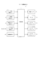
- FIG. 2 is an electrical block diagram of the card processing apparatus of FIG.
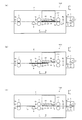
- FIG. 3 is an operation diagram of the card processing apparatus of FIG.
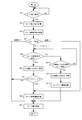
- FIG. 4 is an operation flowchart of the card processing apparatus of FIG.
- FIG. 5 is a diagram showing a card having a deformed portion.
- FIG. 6 is a structural diagram of an IC contact unit of the card processing apparatus of FIG.
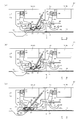
- FIG. 7 is an operation diagram of the IC contact unit of FIG.
- FIG. 8 is an operation diagram of the IC contact unit of FIG.
- FIG. 9 is a structural diagram of an IC contact unit according to another embodiment of the present invention.
- FIG. 10 is a structural diagram of an IC contact unit according to another embodiment of the present invention.
- FIG. 11 is a structural diagram of an IC contact unit according to another embodiment of the present invention.
- FIG. 1 the state of the inside of the card processing apparatus 100 viewed from the side is shown in (a), and the state viewed from above is shown in (b).
- the card processing device 100 is mounted on, for example, an ATM (automatic cash deposit machine) installed in a financial institution.
- the card processing apparatus 100 receives a card 10 owned by a customer and performs information reading and writing processing on the card 10.
- the card 10 handled by the card processing apparatus 100 includes an IC card having an IC contact 10a, a hybrid card having an IC contact 10a and a magnetic stripe 10b, or a magnetic card having a magnetic stripe.
- a card insertion detection sensor 3 As shown in FIG. 1, a card insertion detection sensor 3, an IC contact detection sensor 4, a magnetic stripe detection sensor 5, and a shutter 6 are provided in the insertion section 1 of the card processing apparatus 100.
- the card insertion detection sensor 3 is composed of a micro switch and the like.
- the card insertion detection sensor 3 detects a predetermined width and thickness of the card 10 inserted from the insertion slot 11 to detect the card 10 and does not detect a foreign object smaller than the card 10.
- the IC contact detection sensor 4 is composed of a magnet and a Hall IC. If the inserted card 10 has an IC contact 10a (FIG. 1B), which is a magnetic material, the magnetic field of the magnet changes. For this reason, the IC contact detection sensor 4 detects the IC contact 10a of the card 10 by detecting the change in the magnetic field of the magnet with the Hall IC.
- the IC contact detection sensor 4 is an example of the “IC card detection means” in the present invention.
- the magnetic stripe detection sensor 5 is composed of a pre-magnetic head.
- the magnetic stripe detection sensor 5 detects magnetic data of the magnetic stripe 10 b of the card 10.
- the card 10 is restricted from moving in the width direction W by the side wall 16 provided on the frame 15 of the card processing apparatus 100 as shown in FIG. Further, the card 10 is restricted from moving in the height directions U and D by the transport roller 7 and an upper wall (not shown) and a lower wall 17 provided on the frame 15.
- the card position detection sensors 8a, 8b, 8c, and 8d shown in FIG. 1 (a) are composed of photosensors.
- the card position detection sensors 8a, 8b, 8c, and 8d are provided at predetermined intervals in the running directions F and B of the card 10, and straddle the running path 14 in the up and down directions U and D, respectively.
- Each of the card position detection sensors 8a to 8d detects the card 10 by being shielded from light by the card 10.
- the magnetic head 9 is provided at a position corresponding to the magnetic stripe 10b of the card 10 and performs information reading and writing processing on the magnetic stripe 10b of the card 10 conveyed in the running directions F and B.
- the card insertion detection sensor 3, the IC contact detection sensor 4, the magnetic stripe detection sensor 5, and the card position detection sensor 8a are provided on the reverse B side of the card 10 from the IC contact unit 20.
- the card position detection sensor 8 b is provided in the area of the IC contact unit 20.
- the IC contact unit 20 is provided on the reverse B side of the card 10 from the magnetic head 9.
- the card position detection sensor 8 c is provided between the IC contact unit 20 and the magnetic head 9.
- the card position detection sensor 8d is provided on the forward F side of the card 10 from the magnetic head 9.
- FIG. 1 The deformed card 10 will be described with reference to FIG.
- the IC contact unit 20 is provided above the traveling path 14 U.
- the control unit 11 shown in FIG. 2 brings the contact 21 of the IC contact unit 20 into contact with the IC contact 10a of the card 10 and performs information reading and writing processing on the IC chip (not shown) of the card 10. .
- the contact 21 is composed of a torsion coil spring, and as shown in FIG. 1B, there are four in the front row (F direction side row) and four in the rear row (B direction side row), for a total of eight. Is provided. As shown in FIG. 6, the holder 22 holds each contact 21 so that the contact portion 21 a of the contact 21 protrudes toward the traveling path 14 (D direction).
- the holder 22 is provided with a claw 23 so as to protrude from the contact 21 toward the traveling path 14 on the forward F side of the card 10. As shown in FIG. 1B, the claw 23 is provided at a position that does not line up on a straight line parallel to the traveling directions F and B with respect to the IC contact 10 a of the card 10 in the traveling path 14.
- a pair of side plates 25 is provided perpendicular to the width direction W of the traveling path 14 on both sides of the holder 22 facing the width direction W of the traveling path 14. As shown in FIG. 6, the pair of side plates 25 is fixed to the frame 15 on the side opposite to the traveling path 14 (upper U side). The pair of side plates 25 are provided with two engaging grooves 26 each including a through hole so as to be aligned in the running directions F and B of the card 10.
- each engagement groove 26 extends in parallel with the traveling path 14 toward the backward direction B of the card 10, and then extends obliquely on the opposite side of the traveling path 14. Further, it extends vertically upward U with respect to the traveling path 14. That is, the engagement groove 26 has a parallel portion 26 a, an inclined portion 26 b, and a vertical portion 26 c with respect to the traveling path 14.
- the vertical portion 26c of the engagement groove 26 on the rear side (B direction side) extends to the opposite side (U direction) to the travel path 14 than the vertical portion 26c of the engagement groove 26 on the front side (F direction side). ing.
- Each engagement protrusion 24 of the holder 22 is engaged with each engagement groove 26 of the pair of side plates 25. Thereby, the holder 22 is supported so that the contact 21 can be moved in and out of the traveling path 14.
- the pair of side plates 25, the engagement groove 26, and the engagement protrusion 24 are an example of the “support means” in the present invention.
- the elastic member 27 is composed of a tension coil spring. One end of the elastic member 27 is hooked on the holder 22, and the other end is hooked on the frame 15. The elastic member 27 urges the holder 22 in an oblique direction away from the travel path 14 (an obliquely upward direction with an acute angle with respect to the B direction and the U direction).
- the solenoid actuator 18 includes a solenoid 30, a plunger 31, a return spring 32, and a retaining pin 33.
- the solenoid actuator 18 is fixed to the frame 15 with the tip of the plunger 31 directed in the forward direction F of the card 10.
- the return spring 32 is provided around the plunger 31 and is fastened by a fastening pin 33.
- the end of the plunger 31 is engaged with one end of an L-shaped arm 34 via a retaining pin 33.
- the bent portion of the L-shaped arm 34 is rotatably supported by a support pin 35.
- the support pin 35 is fixed to the frame 15.
- the other end of the L-shaped arm 34 extends to the convex portion 28 of the holder 22.
- the convex portion 28 is provided above the engagement protrusion 24 on the front side (F direction side).
- the solenoid actuator 19 has a solenoid 36, a plunger 37, a return spring 38, and a retaining pin 39.
- the solenoid actuator 19 is fixed to the frame 15 with the tip of the plunger 37 facing the forward direction F of the card 10.
- the return spring 38 is provided around the plunger 37 and is fastened by a fastening pin 39.
- One end of the L-shaped arm 40 is engaged with the tip of the plunger 37 via a retaining pin 39.
- the bent portion of the L-shaped arm 40 is rotatably supported by a support pin 41.
- the support pin 41 is fixed to the frame 15.
- the other end of the L-shaped arm 40 extends to the convex portion 29 of the holder 22.
- the convex portion 29 is provided above the engagement protrusion 24 on the rear side (B direction side).
- the tip 10 c of the card 10 when the tip 10 c of the card 10 is broken and rolled, a deformed portion 10 x protruding from the surface of the card 10 is generated.
- the deformed portion 10x When the deformed portion 10x is in the region 10z in FIG. 1B in which the IC contact 10a of the card 10 on the travel path 14 is extended in the traveling directions F and B, the deformed portion 10x becomes the contact 21. If it contacts, the contactor 21 will be damaged.
- a lever 42 and a movement detection sensor 44 are provided on the reverse side (B side) of the card 10 from the holder 22 and the card position detection sensor 8b.
- the lever 42 is provided across the installation width Wc of the contactor 21 parallel to the width direction W of the travel path 14 as shown in FIG. Further, as shown in FIG. 6, the lever 42 is rotatably supported at one end by a support pin 43.
- the support pin 43 is fixed to the frame 15.
- the surface 42 a of the lever 42 on the traveling path 14 side is inclined in an arc shape on the opposite side of the traveling path 14 with respect to the traveling directions F and B of the card 10.
- the movement detection sensor 44 is composed of a photo sensor and is mounted on a substrate 45 disposed above the lever 42.
- the substrate 45 is fixed with respect to the frame 15.
- the lever 42 holds the posture shown in FIG. 6 by a torsion coil spring (not shown) attached to the support pin 43 so that the other end of the lever 42 is positioned directly below the movement detection sensor 44.
- the card insertion detection sensor 3 detects the card 10 and switches to the ON state. For this reason, the control unit 11 determines that the card 10 has been inserted (step S1: YES in FIG. 4), and executes a card take-in process and a card recording unit detection process (steps S2 and S3).
- the control unit 11 closes the shutter 6 using the solenoid actuator 13.
- the control unit 11 drives the IC contact detection sensor 4 and the magnetic stripe detection sensor 5. Then, based on the output signals of the IC contact detection sensor 4 and the magnetic stripe detection sensor 5, it is determined whether or not the card 10 has the IC contact 10a and the magnetic stripe 10b. This determination result is recorded in the internal memory of the control unit 11.
- step S4 determines the type of the inserted card 10 (step S4). If the IC contact 10a is detected by the IC contact detection sensor 4 in step S3 and the magnetic stripe 10b is not detected by the magnetic stripe detection sensor 5, it is determined in step S4 that the card 10 is an IC card. In step S3, if both the IC contact 10a and the magnetic stripe 10b are detected by the sensors 4 and 5, the card 10 is determined to be a hybrid card in step S4.
- an area 10z ′ (from the tip 10c of the card 10 to the IC contact 10a) ( 1B and FIG. 5), when the deformed portion 10x is not present, the card 10 passes through the position facing the lever 42 without contacting the lever 42 as shown in FIG.
- control unit 11 does not detect the deformed portion 10x of the card 10 by the movement detection sensor 44 (step S5: NO in FIG. 4), and holds the card 10 in front of the IC contact unit 20 by the card position detection sensor 8b. It detects (step S10: YES).
- control unit 11 lowers the holder 22 by the solenoid actuator 18 and the L-shaped arm 34 (step S11). That is, the solenoid 30 is operated to suck the plunger 31 and move the holder 22 in the D direction so as to approach the travel path 14 with the L-shaped arm 34 as shown in FIG. Thereby, the nail
- the control unit 11 performs information processing on the IC chip of the card 10 via the contact 21 and the IC contact 10a (step S12 in FIG. 4). Further, since the contact state between the contact 21 and the IC contact 10 a is maintained by the elastic force of the contact 21, the control unit 11 stops the solenoid 30 of the solenoid actuator 18 and releases the suction to the plunger 31. As a result, the plunger 31 returns to the most protruding state by the elastic force of the return spring 32, and the pressing of the L-shaped arm 34 against the holder 22 is released.
- step S9 the control unit 11 executes a card discharge process (step S9). Specifically, the motor 12 is driven, the transport roller 7 is reversed, and the card 10 is transported in the reverse direction B. At this time, as the card 10 moves away from the claw 23, the holder 22 moves away from the travel path 14 by the elastic force of the elastic member 27, and returns to a posture parallel to the travel path 14 as shown in FIG. To do.
- the control unit 11 opens the shutter 6 by the solenoid actuator 13, and stops the motor 12 after a predetermined time has elapsed. Thereby, the card 10 is conveyed to the insertion part 1, and the card 10 stops in a state where the rear end 10d of the card 10 protrudes from the insertion port 11 (state of FIG. 1).
- the deformed portion 10x when it is determined that the card 10 is an IC card or a hybrid card, when the deformed portion 10x is present in the area 10z ′ of the card 10 as shown in FIG. The deformed portion 10x contacts the lever 42 when passing through the facing position.
- control unit 11 retracts the holder 22 to the opposite side of the traveling path 14 by the solenoid actuator 19, the L-shaped arm 40, and the elastic member 27 (step S6).
- the solenoid 36 is operated to suck the plunger 37 and release the pressing of the L-shaped arm 40 against the holder 22 as shown in FIG. Then, the holder 22 is moved in the U direction so as to be separated from the travel path 14 by the elastic force of the elastic member 27.
- the contact 21 moves away from the travel path 14, so that even if the card 10 is transported to the position facing the holder 22, the deformed portion 10 x is moved to the contact 21 as shown in FIG. None touch.
- the solenoid 30 of the solenoid actuator 18 is stopped, the claw 23 is in a position retracted from the travel path 14.
- the claw 23 is provided at a position where it does not contact the area 10z of the card 10 (see FIG. 1B), the deformed portion 10x of the card 10 does not contact the claw 23.
- step S9 After retracting the holder 22 in step S6, if the card 10 is not a hybrid card (step S7: NO), the controller 11 executes a card discharge process (step S9).
- step S7 if the card 10 is a hybrid card (step S7: YES), information processing is executed on the magnetic stripe 10b of the card 10 (step S8). Specifically, while confirming the position of the card 10 by the card position detection sensors 8a to 8d, the motor 12 is driven to rotate the transport roller 7 forward or backward. Then, as shown in FIGS. 3B and 3C, information is read from and written to the magnetic stripe 10b of the card 10 by the magnetic head 9 while the card 10 is moved forward or backward. After the completion of this process, the control unit 11 executes a card discharge process (step S9 in FIG. 4).
- the solenoid 36 of the solenoid actuator 19 is operating at the start of the card ejection process, the card 10 is transported in the backward direction B, and a predetermined time has elapsed after the card 10 is no longer detected by the card position detection sensor 8b. Then, the control unit 11 stops the solenoid 36. As a result, as shown in FIG. 6, the plunger 37 is returned to the most protruding state by the elastic force of the return spring 38, the L-shaped arm 40 presses the convex portion 29 of the holder 22, and the holder 22 is parallel to the traveling path 14. Return to the correct posture.
- the control unit 11 determines that the card 10 is in step S4. Judged to be a magnetic card. And the control part 11 performs a process of information with respect to the magnetic stripe 10b of the card
- step S3 if neither the IC contact 10a nor the magnetic stripe 10b is detected by the IC contact detection sensor 4 or the magnetic stripe detection sensor 5, the card 10 is excluded from the target card by the control unit 11 in step S4. It is judged that. In this case, the control unit 11 executes card discharge processing (step S9).
- the deformed portion 10x contacts the lever 42 during the execution of steps S8 and S9.
- the controller 11 detects the deformed portion 10x of the card 10.
- the control unit 11 retracts the holder 22 to the opposite side of the traveling path 14 by the solenoid actuator 19, the L-shaped arm 40, and the elastic member 27.
- the solenoid 36 is operated to suck the plunger 37 and release the pressing of the L-shaped arm 40 against the holder 22 as shown in FIG.
- the holder 22 is moved away from the travel path 14 by the elastic force of the elastic member 27.
- the contact 21 moves in the U direction so as to be away from the travel path 14, and does not come into contact with the deformed portion 10 x of the card 10.
- the tip 10 c and the deformed portion 10 x of the card 10 do not contact the claw 23.
- the deformed portion 10x is detected so that the contact 21 and the claw 23 do not contact the card 20.
- the holder 22 is retracted to the side opposite to the traveling path 14. For this reason, the card 10 can pass through the position facing the holder 22 while preventing the contact 21 from being damaged.
- the solenoid 30 is operated and the solenoid 36 is stopped until the IC card 10 without the deformed portion 10x is conveyed to the position facing the holder 22.
- the holder 22 can be moved in advance so as to approach the traveling path 14, the claw 23 can be protruded to the traveling path 14, and the contact 21 can be brought close to the traveling path 14. Therefore, the tip 10c of the IC card 10 that has been conveyed is brought into contact with the claw 23, the holder 22 is pulled toward the card 10 by the conveying force of the card 10, and the contact 21 is brought into contact with the IC contact 10a of the IC card 10. Can be reliably contacted.
- the holder 22 is moved away from the traveling path 14 by the elastic force of the elastic member 27, and the solenoid actuator 19 is used for suppressing the movement. That is, the solenoid actuator 19 performs an auxiliary function for retracting the holder 22. Further, the solenoid actuator 18 is used for lowering the holder 22, the contact 21 is pressed against the IC contact 10 a of the card 10 by the conveying force of the card 10, and the pressed state is maintained by the elastic force of the contact 21. Yes. That is, the solenoid actuator 18 performs an auxiliary function for bringing the contact 21 into contact with the IC contact 10 a of the card 10. For this reason, it is possible to achieve downsizing, cost reduction, and power saving of the card processing apparatus 100 using the small solenoid actuators 18 and 19 having a small operating force.
- the lever 42 is provided over the installation width Wc of the contact 21, it is possible to reliably detect the deformed portion 10 x and the like in the vicinity of the IC contact portion 10 a of the card 10 that may damage the contact 21. Can do.
- the present invention can employ various embodiments other than the above-described embodiments.
- an example in which the arc-shaped lever 42 is used as the moving body for detecting the deformed portion 10x of the card 10 is shown, but the present invention is not limited to this.
- a rotating body 46 as shown in FIG. 9 may be used.
- the rotating body 46 moves (rises) to the opposite side of the traveling path 14 while rotating.
- the movement detection sensor 44 is shielded by the rotating shaft 47, and it is detected that the card 10 has the deformed portion 10x.
- the solenoid 36 of the solenoid actuator 19 operates to release the pressing of the L-shaped arm 40 against the holder 22, and the holder 22 is retracted to the opposite side of the traveling path 14 by the elastic force of the elastic member 27.
- the rotating body 46 when the deformed portion 10x of the card 10 comes into contact, the rotating body 46 moves to the opposite side of the traveling path 14 while rotating, so that the card 10 is more difficult to be caught. Can do.
- the images of the surface inside the area 10z and the outside of the area 10z of the card 10 shown in FIG. 5 are compared. If there is a deformed portion 10x protruding in the area 10z, the portion is not within the distance range that can be normally read by the image reader 49, so that the image is out of focus or the reflected light of the light from the image reader 49 affects the image. To do. For this reason, the presence or absence of the deformation
- some card processing devices have a built-in image reader for reading characters and designs printed on the card.
- the image reader can be used as it is for detecting a deformed portion of the card.
- the deformed portion 10x of the card 10 can be detected in a non-contact manner. For this reason, it is possible to prevent the detection performance of the deformed portion 10x of the card 10 from deteriorating due to deterioration of parts due to contact with the card 10 or aging.
- the actuators 18 and 19 using the solenoids 30 and 36 as drive sources are shown as examples.
- the present invention is not limited to this, and other than this, for example, a motor is used as the drive source. You may use the actuated actuator.
- the engagement protrusion 24 is provided in the holder 22 and the engagement groove 26 is provided in the pair of side plates 25 has been shown, but the present invention is not limited to this.
- the engagement groove 26 may be provided in the holder 22, and the engagement protrusions 24 may be provided in the pair of side plates 25.
- the present invention is applied to the hybrid type card processing apparatus 100 including the magnetic head 9 in addition to the IC contact unit 20. It can be applied to card processing devices dedicated to IC cards that are not provided, or card processing devices that can handle both contact IC cards and non-contact IC cards, including contact IC heads in addition to contact IC heads. It is.
- the present invention is useful for a card processing apparatus having a configuration for collecting an abnormal card having a deformed portion on the side opposite to the card insertion slot.
- the present invention can also be applied to a manual card processing apparatus.
Landscapes
- Engineering & Computer Science (AREA)
- Physics & Mathematics (AREA)
- General Physics & Mathematics (AREA)
- Theoretical Computer Science (AREA)
- Artificial Intelligence (AREA)
- Computer Vision & Pattern Recognition (AREA)
- Conveying Record Carriers (AREA)
Abstract
カード(10)の突出した変形部分(10x)をレバー(42)と移動検知センサ(44)により検知する。変形部分(10x)を検知すると、ソレノイドアクチュエータ(19)を動作させて、L形アーム(40)を回転させ、L形アーム(40)のホルダ(22)に対する押さえを解除する。これにより、弾性部材(27)の弾性力でホルダ(22)が走行路(14)と反対側(U方向)へ退避するので、カード(10)に変形部分(10x)があっても、カード(10)はホルダ(22)との対向位置を通過することができる。
Description
本発明は、カードのIC接点に接触子を接触させて、情報の処理を行う接触式のカード処理装置に関する。
接触式のカード処理装置は、カードのIC接点に接触子を接触させ、接触子とIC接点を介して、カードのICチップに対して情報の読み取りや書き込みの処理を行う。この接触式のカード処理装置には、たとえば、特許文献1および2に開示されているような、IC接触ユニットが備わっている。
このIC接触ユニットでは、接触子が、カードの走行路側へ突出するように、ホルダで保持されている。また、ホルダには、接触子よりカードの前進側で走行路側へ突出するように、爪が設けられている。さらに、ホルダは、コイルスプリングにより、走行路から離れる方向に付勢されている。
また、特許文献1では、ブラケットの両側板に設けられたガイド孔に、ホルダに設けられた軸を挿入して、接触子と爪が走行路に対して出没可能になるように、ホルダを支持している。そして、カードがホルダとの対向位置へ前進して来るまでに、アクチュエータの作動力でホルダを走行路側へ押し下げて、爪を走行路へ突出させる。これにより、搬送手段により搬送されて来たカードの先端が爪に当接して、カードの搬送力によりホルダがカード側に引き寄せられて、接触子がカードのIC接点に接触する。
また、特許文献2では、接触子が走行路に対して出没可能になるように、リンクでホルダを支持している。そして、通常状態で爪を走行路へ突出させておき、挿入されたカードの先端が爪に当接して、カードの挿入力によりホルダがカード側に引き寄せられて、接触子がカードのIC接点に接触する。
特許文献1および2のように、予め爪を走行路へ突出させておくことで、接触子が走行路に接近し、カードの前進速度が速くても、カードの先端を爪で係止して、カードのIC接点に接触子を確実に接触させることができる。また、ホルダと走行路との間隔を狭く設定することで、カード処理装置を高さ方向に小型化することが可能となる。
ところが、ホルダから接触子が走行路側に突出しているので、カードに、該カードの表面からホルダ側へ突出した変形部分がある場合、カードが前進して来たときに、該変形部分が接触子に接触して、接触子が損傷し、機能を損なうおそれがある。特に、カードの待ち受け状態で接触子が走行路に接近しているほど、接触子を損傷し易い。
そこで、特許文献2では、接触子よりカードの後進側に、カードの変形部分を引っ掛けて係止する規制溝を設けている。しかし、規制溝でカードの変形部分を引っ掛けると、そこから先へカードが前進できなくなる。
このため、たとえば、特許文献1のように、IC接触ユニットと磁気ヘッドを備えたハイブリッド型のカード処理装置に、特許文献2のような規制溝を設けた場合、IC接点と磁気ストライプを有したハイブリッドカードに突出した変形部分があると、該カードが使用できなくなる。つまり、変形部分のあるカードが規制溝で係止されて、ホルダとの対向位置を通過できなくなるので、該カードを搬送しながら、磁気ヘッドで磁気ストライプに対して情報を処理できなくなる。この他にも、たとえば、変形部分のあるカードをホルダの先にある回収部に回収できなくなるという問題がある。
一方、特許文献3には、異常形状のカードを識別するカード処理装置が開示されている。この装置では、挿入部に設けたプリヘッドによりカードの磁気情報を検知せずに、本体内に設けたカード検知センサによりカード長の異常を検知した場合に、カードが異常形状カードであると識別している。しかし、この方法では、カードの表面から突出した変形部分を検知することはできない。
本発明の課題は、カードに突出した変形部分があっても、接触子が損傷するのを防止しつつ、カードがホルダとの対向位置を通過可能なカード処理装置を提供することである。
本発明では、カードのIC接点と接触する接触子と、接触子をカードの走行路側へ突出するように保持するホルダと、接触子よりカードの前進側で走行路側へ突出するようにホルダに設けられた爪と、接触子が走行路に対して出没可能になるように、ホルダを支持する支持手段とを備え、予め、爪を走行路へ突出させておき、前進して来たカードの先端を爪に当接させて、カードの前進力によりホルダをカード側に引き寄せることにより、接触子をカードのIC接点に接触させて情報の処理を行うカード処理装置において、さらに、ホルダよりカードの後進側に設けられ、カードの表面から突出した変形部分を検知するカード変形検知手段と、カード変形検知手段によりカードの変形部分を検知した場合に、接触子および爪がカードに接触しないように、ホルダを走行路と反対側へ退避させる退避手段とを備える。
上記によると、前進して来たカードに突出した変形部分があっても、該変形部分をカード変形検知手段により検知して、接触子および爪がカードに接触しないように、退避手段によりホルダを走行路と反対側へ退避させる。このため、接触子が損傷するのを防止しつつ、カードがホルダとの対向位置を通過することが可能となる。
また、本発明では、上記カード処理装置において、以下のような構成を採用してもよい。
支持手段を、ホルダに対して走行路の幅方向を向いた両側方に、走行路の幅方向に対して垂直に設けられた一対の側板と、一対の側板およびホルダのうちの一方に設けられ、カードの後進方向に向かって、走行路と平行に延びてから、走行路と反対側に斜め方向に延びて、さらに走行路に対して垂直に延びる係合溝と、一対の側板およびホルダのうちの他方に設けられ、係合溝に係合する係合突起とから構成する。
第1駆動源を有し、この第1駆動源の動作時にホルダを走行路へ近づくように押さえて、爪を走行路へ突出させ、第1駆動源の非動作時にホルダに対する押さえを解除する第1アクチュエータを備える。
退避手段を、ホルダを走行路から離れる方向へ付勢する弾性部材と、第2駆動源を有し、この第2駆動源の非動作時にホルダを走行路と反対側へ移動しないように押さえ、第2駆動源の動作時にホルダに対する押さえを解除する第2アクチュエータとから構成する。
支持手段を、ホルダに対して走行路の幅方向を向いた両側方に、走行路の幅方向に対して垂直に設けられた一対の側板と、一対の側板およびホルダのうちの一方に設けられ、カードの後進方向に向かって、走行路と平行に延びてから、走行路と反対側に斜め方向に延びて、さらに走行路に対して垂直に延びる係合溝と、一対の側板およびホルダのうちの他方に設けられ、係合溝に係合する係合突起とから構成する。
第1駆動源を有し、この第1駆動源の動作時にホルダを走行路へ近づくように押さえて、爪を走行路へ突出させ、第1駆動源の非動作時にホルダに対する押さえを解除する第1アクチュエータを備える。
退避手段を、ホルダを走行路から離れる方向へ付勢する弾性部材と、第2駆動源を有し、この第2駆動源の非動作時にホルダを走行路と反対側へ移動しないように押さえ、第2駆動源の動作時にホルダに対する押さえを解除する第2アクチュエータとから構成する。
これにより、予め、第1駆動源を動作させかつ第2駆動源を停止させておくことで、第1アクチュエータによりホルダを走行路へ近づくように移動させて、爪を走行路へ突出させ、接触子を走行路に接近させておくことができる。このため、前進して来たカードの先端を爪に当接させ、カードの前進力によりホルダをカード側に引き寄せて、接触子をカードのIC接点に確実に接触させることができる。
また、カードに突出した変形部分がある場合に、第1駆動源を停止させかつ第2駆動源を動作させることで、第2アクチュエータのホルダに対する押さえを解除し、弾性部材の弾性力によりホルダを走行路と反対側へ退避させて、爪および接触子がカードに接触するのを確実に回避することができる。
また、弾性部材の弾性力でホルダを走行路から離れるように移動させ、該移動の抑止用に第2アクチュエータを使用する。つまり、ホルダを退避させるための補助的な働きを、第2アクチュエータで行っている。また、ホルダの走行路側への移動用に第1アクチュエータを使用し、カードの前進力で接触子をカードのIC接点に押圧して、該押圧状態を接触子の弾性力により維持している。つまり、接触子をIC接点に接触させるための補助的な働きを、第1アクチュエータで行っている。このため、作動力が小さい小型のアクチュエータを用いて、カード処理装置の小型化、低コスト化、および省電力化を達成することができる。
また、本発明では、上記カード処理装置において、さらに、ホルダよりカードの後進側に設けられたICカード検知手段を備え、ICカード検知手段によりICカードを検知し、かつ、カード変形検知手段によりカードの変形部分を検出しなかった場合に、第1駆動源を動作させて、第1アクチュエータによりホルダを走行路へ近づくように押さえて、爪を走行路へ突出させてもよい。
これにより、突出した変形部分のないICカードが前進して来た場合に、ホルダを走行路へ近づくように押さえて、爪を走行路へ突出させることができる。
また、本発明の一実施形態では、上記カード処理装置において、カード変形検知手段を、走行路の幅方向と平行な接触子の設置幅に渡って設けられ、カードの変形部分が接触することで走行路と反対側に移動する移動体と、移動体の移動を検知する移動検知センサと、から構成し、カードの変形部分が接触する移動体の接触部分を、カードの走行方向に対して走行路と反対側に傾斜させてもよい。
これにより、接触子を損傷させるおそれのある、カードのIC接点近傍の突出した変形部分を確実に検知することができる。また、移動体の接触部分を傾斜させているので、カードの変形部分が接触しても、カードが引っ掛かるのを防止することができる。このため、移動体を走行路と反対側に移動させつつ、突出した変形部分のあるカードが移動体との対向位置を通過することが可能となる。
また、本発明の一実施形態では、上記カード処理装置において、移動体を回転体から構成し、回転体の回転軸を走行路の幅方向と平行にしてもよい。
これにより、カードの突出した変形部分が接触したときに、回転体が回転しながら走行路と反対側へ移動するので、カードをより引っ掛かり難くすることができる。
また、本発明の他の実施形態では、上記カード処理装置において、カード変形検知手段を、カードの表面を撮影した画像に基づいて、カードの突出した変形部分を検知するイメージリーダから構成してもよい。
これにより、カードの突出した変形部分を非接触で検知することができる。このため、カードとの接触や経年変化による部品の劣化が原因で、カードの変形部分の検知性能が低下するのを防止することが可能となる。
さらに、本発明では、上記カード処理装置において、さらに、カードを走行路に沿って搬送するカード搬送手段と、カードの磁気ストライプに対応する位置に設けられた磁気ヘッドとを備え、カード変形検知手段によりカードの突出した変形部分を検知して、退避手段によりホルダを走行路と反対側へ退避させた後、カード搬送手段によりカードを搬送しながら、磁気ヘッドによりカードの磁気ストライプに対して情報の処理を行ってもよい。
これにより、IC接点と磁気ストライプを有するハイブリッドカードに変形部分があっても、ホルダを退避させて、接触子の損傷を防止することができる。また、そのハイブリッドカードをホルダとの対向位置へ通過させながら、磁気ヘッドで磁気ストライプに対して情報の処理を行うことができる。
本発明によれば、カードに突出した変形部分があっても、接触子が損傷するのを防止しつつ、カードがホルダとの対向位置を通過可能なカード処理装置を提供することができる。
以下、本発明の実施形態につき、図面を参照しながら説明する。各図において、同一の部分または対応する部分には、同一符号を付してある。
まず、本発明の一実施形態によるカード処理装置100の全体構成を、図1および図2を参照しながら説明する。なお、図1では、カード処理装置100の内部を、側方から見た状態を(a)に示し、上方から見た状態を(b)に示している。
カード処理装置100は、たとえば、金融機関に設置されたATM(現金自動預金支払機)に実装される。カード処理装置100は、顧客が所有するカード10を受け付けて、カード10に対して情報の読み取りと書き込みの処理を行う。カード処理装置100で取り扱われるカード10は、IC接点10aを有するICカード、IC接点10aと磁気ストライプ10bを有するハイブリッドカード、または磁気ストライプを有する磁気カードから成る。
図1に示すように、カード処理装置100の挿入部1には、カード挿入検知センサ3、IC接点検知センサ4、磁気ストライプ検知センサ5、およびシャッタ6が設けられている。
カード挿入検知センサ3は、マイクロスイッチなどから構成されている。カード挿入検知センサ3は、挿入口11から挿入されたカード10の所定の幅や厚みを感知して、カード10を検知し、カード10より小さい異物は検知しない。
IC接点検知センサ4は、磁石とホールICなどから構成されている。挿入されたカード10に磁性体であるIC接点10a(図1(b))があると、磁石の磁界が変化する。このため、IC接点検知センサ4は、磁石の磁界の変化をホールICで感知して、カード10のIC接点10aを検知する。IC接点検知センサ4は、本発明の「ICカード検知手段」の一例である。
磁気ストライプ検知センサ5は、プリ磁気ヘッドから構成されている。磁気ストライプ検知センサ5は、カード10の磁気ストライプ10bの磁気データを検知する。
シャッタ6は、ソレノイドアクチュエータ13(図2)の作動力により上下方向U、Dへ往復移動して、挿入部1内と本体2内を連通させる開口を開閉する。
カード処理装置100の本体2には、図1に示す、搬送ローラ7、カード位置検知センサ8a、8b、8c、8d、磁気ヘッド9、およびIC接触ユニット20、並びに、図2に示す、制御部11、モータ12、およびソレノイドアクチュエータ13、18、19が設けられている。
搬送ローラ7は、図1(a)に示すように、上下一対で構成され、カード10の走行方向F、Bに所定の間隔で三対設けられている。搬送ローラ7は、カード10を挟持して、モータ12(図2)の駆動力により正転または逆転する。これにより、カード10が走行路14に沿って前進方向Fまたは後進方向Bへ搬送される。搬送ローラ7とモータ12は、本発明の「カード搬送手段」の一例である。
走行路14において、カード10は、図1(b)に示すように、カード処理装置100のフレーム15に設けられた側壁16により、幅方向Wへの移動を制限されている。また、カード10は、搬送ローラ7と、フレーム15に設けられた上壁(図示省略)および下壁17により、高さ方向U、Dへの移動を制限されている。
図1(a)に示す、カード位置検知センサ8a、8b、8c、8dは、フォトセンサから構成されている。カード位置検知センサ8a、8b、8c、8dは、カード10の走行方向F、Bに所定の間隔で設けられ、それぞれ走行路14を上下方向U、Dに跨いでいる。各カード位置検知センサ8a~8dは、カード10で遮光されることにより、カード10を検知する。
磁気ヘッド9は、カード10の磁気ストライプ10bに対応する位置に設けられており、走行方向F、Bへ搬送されるカード10の磁気ストライプ10bに対して、情報の読み取りや書き込みの処理を行う。
図2に示す制御部11は、マイクロコンピュータなどから構成され、各部の動作を制御する。制御部11は、カード挿入検知センサ3の出力信号に基づいて、カード10の挿入を検出する。また、制御部11は、IC接点検知センサ4と磁気ストライプ検知センサ5の出力信号に基づいて、挿入されたカード10の種別を判断する。また、制御部11は、カード位置検知センサ8a~8dの出力信号に基づいて、カード10の位置を検出する。
カード挿入検知センサ3、IC接点検知センサ4、磁気ストライプ検知センサ5、およびカード位置検知センサ8aは、IC接触ユニット20よりカード10の後進B側に設けられている。カード位置検知センサ8bは、IC接触ユニット20の領域に設けられている。IC接触ユニット20は、磁気ヘッド9よりカード10の後進B側に設けられている。カード位置検知センサ8cは、IC接触ユニット20と磁気ヘッド9の間に設けられている。カード位置検知センサ8dは、磁気ヘッド9よりカード10の前進F側に設けられている。
次に、IC接触ユニット20の構造を、図1、図2、および図6~図8を参照しながら説明する。また、変形したカード10について、図5を参照しながら説明する。
図6に示すように、IC接触ユニット20には、接触子21、ホルダ22、側板25、弾性部材27、ソレノイドアクチュエータ18、19、L形アーム34、40、レバー42、および移動検知センサ44が備わっている。なお、図6の(a)は、IC接触ユニット20の側面図、(b)は、ホルダ22部分での断面側面図を表している。図7~図11における各図も、ホルダ22部分での断面側面図を表している。
IC接触ユニット20は、走行路14より上方Uに設けられている。図2に示した制御部11は、IC接触ユニット20の接触子21をカード10のIC接点10aに接触させ、カード10のICチップ(図示省略)に対して情報の読み取りや書き込みの処理を行う。
接触子21は、ねじりコイルばねから構成され、図1(b)に示すように、前列(F方向側の列)に4つ、後列(B方向側の列)に4つ、全部で8つ設けられている。ホルダ22は、図6に示すように、接触子21の接点部21aが走行路14側(D方向)へ突出するように、各接触子21を保持している。
ホルダ22には、接触子21よりカード10の前進F側で走行路14側へ突出するように、爪23が設けられている。爪23は、図1(b)に示すように、走行路14にあるカード10のIC接点10aに対して、走行方向F、Bと平行な一直線上に並ばない位置に設けられている。
ホルダ22において、走行路14の幅方向Wを向いた両側面には、係合突起24がカード10の走行方向F、Bに並ぶように2つずつ設けられている。
ホルダ22に対して、走行路14の幅方向Wを向いた両側方には、走行路14の幅方向Wに対して垂直に一対の側板25が設けられている。一対の側板25は、図6に示すように、走行路14と反対側(上方U側)を、フレーム15に固定されている。一対の側板25には、貫通孔から成る係合溝26がカード10の走行方向F、Bに並ぶように2つずつ設けられている。
各係合溝26は、図6(a)に示すように、カード10の後進方向Bに向かって、走行路14と平行に延びてから、走行路14と反対側に斜め方向に延びて、さらに走行路14に対して上方Uへ垂直に延びている。すなわち、係合溝26は、走行路14に対して平行部26aと傾斜部26bと垂直部26cを有している。後ろ側(B方向側)にある係合溝26の垂直部26cは、前側(F方向側)にある係合溝26の垂直部26cよりも、走行路14と反対側(U方向)に延びている。
ホルダ22の各係合突起24は、一対の側板25の各係合溝26に係合されている。これにより、接触子21が走行路14に対して出没可能になるように、ホルダ22が支持されている。一対の側板25、係合溝26、および係合突起24は、本発明の「支持手段」の一例である。
弾性部材27は、引っ張りコイルばねから構成されている。弾性部材27の一端は、ホルダ22に引っ掛けられ、他端は、フレーム15に引っ掛けられている。弾性部材27は、ホルダ22を走行路14から離れる斜め方向(B方向およびU方向に対して鋭角な斜め上方向)へ付勢している。
ソレノイドアクチュエータ18は、ソレノイド30、プランジャ31、復帰ばね32、および留めピン33を有している。ソレノイドアクチュエータ18は、プランジャ31の先端をカード10の前進方向Fへ向けた状態で、フレーム15に固定されている。復帰ばね32は、プランジャ31の周囲に設けられ、留めピン33で留められている。
プランジャ31の先端には、L形アーム34の一端が留めピン33を介して係合されている。L形アーム34の屈曲部は、支持ピン35で回動可能に支持されている。支持ピン35は、フレーム15に対して固定されている。L形アーム34の他端は、ホルダ22の凸部28上まで伸びている。凸部28は、前側(F方向側)の係合突起24の上方Uに設けられている。
ソレノイドアクチュエータ18では、ソレノイド30が動作(励磁)すると、図7(a)に示すように、プランジャ31が吸引されて、L形アーム34が支持ピン35を中心に時計回りに回動し、ホルダ22が走行路14へ近づくように、凸部28を下方Dへ押さえる。これにより、ホルダ22が前傾して、爪23が走行路14へ突出し、接触子21が走行路14に接近する。
また、ソレノイド30が停止すると(非動作状態)、図6に示すように、プランジャ31が復帰ばね32の弾性力により吸引前の最突出状態に復帰して、L形アーム34が支持ピン35を中心に反時計回りに回動し、ホルダ22の凸部28に対する押さえを解除する。これにより、ホルダ22が走行路14と平行な姿勢に復帰して、爪23が走行路14から退避し、接触子21が走行路14から離れる。
ソレノイドアクチュエータ18とL形アーム34は、本発明の「第1アクチュエータ」の一例である。ソレノイド30は、本発明の「第1駆動源」の一例である。
ソレノイドアクチュエータ19は、ソレノイド36、プランジャ37、復帰ばね38、および留めピン39を有している。ソレノイドアクチュエータ19は、プランジャ37の先端をカード10の前進方向Fへ向けた状態で、フレーム15に固定されている。復帰ばね38は、プランジャ37の周囲に設けられ、留めピン39で留められている。
プランジャ37の先端には、L形アーム40の一端が留めピン39を介して係合されている。L形アーム40の屈曲部は、支持ピン41で回動可能に支持されている。支持ピン41は、フレーム15に対して固定されている。L形アーム40の他端は、ホルダ22の凸部29上まで伸びている。凸部29は、後ろ側(B方向側)の係合突起24の上方Uに設けられている。
ソレノイドアクチュエータ19では、ソレノイド36が停止しているとき(非動作時)、図6に示すように、プランジャ37が最突出状態にあり、L形アーム40がホルダ22の凸部29を押さえている。これにより、ホルダ22が弾性部材27の弾性力(引っ張り力)によって走行路14と反対側へ移動するのが規制されている。また、爪23および接触子21の走行路14に対する所定の間隔が保持されている。この所定の間隔は、カード位置検知センサ8bでカード10を検知したときに、ソレノイドアクチュエータ18の作動力によりホルダ22を走行路14へ近づくように移動させて、爪23および接触子21をカード10に確実に接触させることが可能な大きさに設定されている。
そして、ソレノイド36が動作すると、図8(b)に示すように、プランジャ37が吸引されて、L形アーム40が支持ピン41を中心に時計回りに回動し、ホルダ22の凸部29に対する押さえを解除する。これにより、弾性部材27の弾性力(引っ張り力)によってホルダ22の後部が走行路14と反対側へ移動して、ホルダ22が前傾する。つまり、ホルダ22が走行路14と反対側へ退避し、接触子21が走行路14から離れる。
また、ソレノイド36が停止すると、図6に示すように、プランジャ37が復帰ばね38の弾性力により吸引前の最突出状態に復帰して、L形アーム40が支持ピン41を中心に反時計回りに回動し、ホルダ22の凸部29を走行路14側へ押さえる。これにより、ホルダ22が走行路14と平行な姿勢に復帰して、接触子21が走行路14に近づく。
ソレノイドアクチュエータ19とL形アーム40は、本発明の「第2アクチュエータ」の一例である。ソレノイド36は、本発明の「第2駆動源」の一例である。ソレノイドアクチュエータ19とL形アーム40と弾性部材27は、本発明の「退避手段」の一例である。
たとえば、図5に示すように、カード10の先端10cが割れて捲れることで、カード10の表面から突出した変形部分10xが生じる。この変形部分10xが、図1(b)における、走行路14にあるカード10のIC接点10aを走行方向F、Bに延長した領域10z内にあった場合、該変形部分10xが接触子21に接触すると、接触子21が損傷してしまう。
そこで、図1(b)および図6に示すように、ホルダ22およびカード位置検知センサ8bよりカード10の後進側(B側)に、レバー42および移動検知センサ44を設けている。
レバー42は、図1(b)に示すように、走行路14の幅方向Wと平行な接触子21の設置幅Wcに渡って設けられている。また、レバー42は、図6に示すように、一端を支持ピン43で回動可能に支持されている。支持ピン43は、フレーム15に対して固定されている。レバー42の走行路14側の面42aは、カード10の走行方向F、Bに対して走行路14と反対側に円弧状に傾斜している。
移動検知センサ44は、フォトセンサから構成されていて、レバー42の上方に配置された基板45に実装されている。基板45は、フレーム15に対して固定されている。移動検知センサ44の直下にレバー42の他端が位置するように、レバー42は、支持ピン43に取り付けられたねじりコイルばね(図示省略)により、図6に示す姿勢を保持している。
図8(b)に示すように、カード10の変形部分10xがレバー42の傾斜面42aに接触することで、レバー42は走行路14と反対側に回動して、移動検知センサ44を遮光する。これにより、移動検知センサ44がレバー42の回動を検知して、該センサ44の出力信号がOFFからONに切り替わり、制御部11(図2)でカード10の変形部分10xが検知される。レバー42は、本発明の「移動体」の一例であり、レバー42と移動検知センサ44は、本発明の「カード変形検知手段」の一例である。
次に、カード処理装置100の動作を、図1~図8を参照しながら説明する。図4のフローチャートに示された各処理は、図2に示した制御部11により実行される。
挿入口11(図1)からカード10が挿入されると、カード挿入検知センサ3がカード10を検知してON状態に切り替わる。このため、制御部11は、カード10が挿入されたと判断し(図4のステップS1:YES)、カード取り込み処理とカード記録部検出処理を実行する(ステップS2、S3)。
ステップS2のカード取り込み処理で、制御部11は、ソレノイドアクチュエータ13(図2)により、図1(a)に示すように、シャッタ6を開き、モータ12(図2)を駆動して、搬送ローラ7を正転させる。これにより、カード10が挿入部1から本体2内へ前進し、搬送ローラ7に挟持されて、前進方向Fに搬送されて行く。
なお、図3に示すように、カード10が本体2内に取り込まれたことを、カード位置検知センサ8a~8dにより検出すると、制御部11は、ソレノイドアクチュエータ13により、シャッタ6を閉じる。
図4のステップS3のカード記録部検出処理で、制御部11は、IC接点検知センサ4と磁気ストライプ検知センサ5を駆動する。そして、IC接点検知センサ4と磁気ストライプ検知センサ5の各出力信号に基づいて、カード10にIC接点10aと磁気ストライプ10bが有るか否かを判断する。この判断結果は、制御部11の内部メモリに記録される。
次に、制御部11は、挿入されたカード10の種別を判断する(ステップS4)。ステップS3で、IC接点検知センサ4によりIC接点10aを検知して、磁気ストライプ検知センサ5により磁気ストライプ10bを検知しなかった場合、ステップS4で、カード10はICカードであると判断される。また、ステップS3で、センサ4、5によりIC接点10aと磁気ストライプ10bの両方を検知した場合、ステップS4で、カード10はハイブリッドカードであると判断される。
カード10がICカードやハイブリッドカードであると判断された場合において、カード10の先端10cからIC接点10aまでの領域10z’(
図1(b)および図5)に変形部分10xがないときは、図6に示すように、カード10がレバー42に接触することなく、レバー42との対向位置を通過する。
図1(b)および図5)に変形部分10xがないときは、図6に示すように、カード10がレバー42に接触することなく、レバー42との対向位置を通過する。
このため、制御部11は、移動検知センサ44によりカード10の変形部分10xを検出することなく(図4のステップS5:NO)、カード位置検知センサ8bによりIC接触ユニット20の手前でカード10を検出する(ステップS10:YES)。
この場合、制御部11は、ソレノイドアクチュエータ18とL形アーム34により、ホルダ22を下降させる(ステップS11)。つまり、ソレノイド30を動作させて、図7(a)に示すように、プランジャ31を吸引し、L形アーム34でホルダ22を走行路14へ近づくようにD方向へ移動させる。これにより、カード10がホルダ22との対向位置へ搬送されて来るまでに、爪23が走行路14へ突出した状態になる。
この後、図7(b)に示すように、カード10がF方向に搬送されて来ると、カード10の先端10cが爪23に当接する。そして、図7(c)に示すように、カード10の搬送力によりホルダ22がカード10側に引き寄せられて、接触子21がカード10のIC接点10a(図1(b))に弾性接触する。
この接触状態で、制御部11は、接触子21とIC接点10aを介して、カード10のICチップに対して情報の処理を実行する(図4のステップS12)。また、接触子21の弾性力により接触子21とIC接点10aとの接触状態が保持されるので、制御部11は、ソレノイドアクチュエータ18のソレノイド30を停止して、プランジャ31に対する吸引を解放する。これにより、プランジャ31が復帰ばね32の弾性力で最突出状態に復帰して、L形アーム34のホルダ22に対する押さえが解除される。
ステップ12の処理完了後、制御部11は、カード排出処理を実行する(ステップS9)。具体的には、モータ12を駆動して、搬送ローラ7を逆転させ、カード10を後進方向Bへ搬送して行く。このとき、カード10が爪23から離れるに連れて、ホルダ22が弾性部材27の弾性力により走行路14から離れるように移動し、図6に示すような、走行路14と平行な姿勢に復帰する。
また、制御部11は、後進方向Bへ搬送されるカード10をカード位置検知センサ8a(図1)により検知すると、ソレノイドアクチュエータ13によりシャッタ6を開き、所定時間経過後に、モータ12を停止させる。これにより、カード10が挿入部1へ搬送されて、カード10の後端10dが挿入口11から突出した状態で、カード10が停止する(図1の状態)。
一方、カード10がICカードまたはハイブリッドカードであると判断した場合において、図8(a)に示すように、カード10の領域10z’に変形部分10xがあるときは、カード10がレバー42との対向位置を通過する際に、変形部分10xがレバー42に接触する。
これにより、図8(b)に示すように、レバー42が回動して、移動検知センサ44を遮光するため、制御部11は、移動検知センサ44によりカード10の変形部分10xを検出する(図4のステップS5:YES)。
この場合、制御部11は、ソレノイドアクチュエータ19とL形アーム40と弾性部材27により、ホルダ22を走行路14と反対側へ退避させる(ステップS6)。つまり、ソレノイド36を動作させて、図8(b)に示すように、プランジャ37を吸引し、L形アーム40のホルダ22に対する押さえを解除する。そして、弾性部材27の弾性力によりホルダ22を走行路14から離れるようにU方向へ移動させる。
これにより、接触子21が走行路14から離れるように移動するので、図8(c)に示すように、カード10がホルダ22との対向位置まで搬送されても、変形部分10xが接触子21に接触することはない。またこのとき、ソレノイドアクチュエータ18のソレノイド30が停止しているので、爪23が走行路14から退避した位置にある。しかも、爪23はカード10の領域10zに接触しない位置に設けられているので(図1(b)参照)、カード10の変形部分10xが爪23に接触することもない。このため、変形部分10xのあるカード10は、接触子21や爪23に接触することなく、図3(a)および(b)に示すように、ホルダ22との対向位置をF方向に通過する。
図4のステップS6でホルダ22を退避させた後、制御部11は、カード10がハイブリッドカードでなければ(ステップS7:NO)、カード排出処理を実行する(ステップS9)。
一方、カード10がハイブリッドカードであれば(ステップS7:YES)、カード10の磁気ストライプ10bに対して情報の処理を実行する(ステップS8)。具体的には、カード位置検知センナ8a~8dによりカード10の位置を確認しながら、モータ12を駆動して、搬送ローラ7を正転または逆転させる。そして、図3(b)および(c)に示すように、カード10を前進または後進させながら、磁気ヘッド9によりカード10の磁気ストライプ10bに対して情報の読み取りや書き込みを行う。この処理の完了後、制御部11は、カード排出処理を実行する(図4のステップS9)。
カード排出処理の開始時に、ソレノイドアクチュエータ19のソレノイド36が動作中である場合は、カード10を後進方向Bへ搬送して、カード位置検知センサ8bでカード10を検知しなくなってから所定時間経過後に、制御部11がソレノイド36を停止させる。これにより、図6に示すように、プランジャ37が復帰ばね38の弾性力で最突出状態に復帰し、L形アーム40がホルダ22の凸部29を押さえて、ホルダ22を走行路14と平行な姿勢に戻す。
また、図4のステップS3で、IC接点検知センサ4によりIC接点10aを検知せずに、磁気ストライプ検知センサ5により磁気ストライプ10bを検知した場合、制御部11は、ステップS4で、カード10は磁気カードであると判断する。そして、制御部11は、カード10の磁気ストライプ10bに対して情報の処理を実行し(ステップS8)、この処理の完了後、カード排出処理を実行する(ステップS9)。
また、ステップS3で、IC接点検知センサ4と磁気ストライプ検知センサ5によりIC接点10aと磁気ストライプ10bをいずれも検知しなかった場合は、ステップS4で制御部11により、カード10は対象外のカードであると判断される。この場合、制御部11は、カード排出処理を実行する(ステップS9)。
また、IC接点10aの有無に関係なく、図5などに示すカード10の領域10zに変形部分10xがある場合、ステップS8およびS9の実行中に、該変形部分10xがレバー42に接触する。これにより、レバー42が回動して、移動検知センサ44を遮光すると、制御部11でカード10の変形部分10xが検出される。
この場合も、制御部11は、ソレノイドアクチュエータ19とL形アーム40と弾性部材27により、ホルダ22を走行路14と反対側へ退避させる。つまり、ソレノイド36を動作させて、図8(b)に示すように、プランジャ37を吸引し、L形アーム40のホルダ22に対する押さえを解除する。そして、弾性部材27の弾性力によりホルダ22を走行路14から離れるように移動させる。これにより、接触子21が走行路14から離れるようにU方向へ移動して、カード10の変形部分10xと接触しなくなる。またこのとき、爪23も走行路14から離れた位置に退避しているため、カード10の先端10cや変形部分10xが爪23に接触することはない。
上記実施形態によると、挿入口11からF方向に前進するカード10に突出した変形部分10xがあっても、該変形部分10xを検知して、接触子21と爪23がカード20に接触しないように、ホルダ22を走行路14と反対側へ退避させている。このため、接触子21が損傷するのを防止しつつ、カード10がホルダ22との対向位置を通過することが可能となる。
また、変形部分10xのないICカード10がホルダ22との対向位置へ搬送されて来るまでに、ソレノイド30を動作させかつソレノイド36を停止させている。これにより、予め、ホルダ22を走行路14へ近づくように移動させて、爪23を走行路14へ突出させ、接触子21を走行路14に接近させておくことができる。このため、搬送されて来たICカード10の先端10cを爪23に当接させ、該カード10の搬送力によりホルダ22をカード10側に引き寄せて、接触子21をICカード10のIC接点10aに確実に接触させることができる。
また、カード10に変形部分10xがある場合に、ソレノイド30を停止させかつソレノイド36を動作させている。これにより、弾性部材27の弾性力によりホルダ22を走行路14と反対側へ退避させて、爪23および接触子21がカード10に接触するのを確実に回避することができる。
また、弾性部材27の弾性力でホルダ22を走行路14から離れるように移動させ、該移動の抑止用にソレノイドアクチュエータ19を使用している。つまり、ホルダ22を退避させるための補助的な働きを、ソレノイドアクチュエータ19で行っている。また、ホルダ22の下降用にソレノイドアクチュエータ18を使用し、カード10の搬送力で接触子21をカード10のIC接点10aに押圧して、該押圧状態を接触子21の弾性力により維持している。つまり、接触子21をカード10のIC接点10aに接触させるための補助的な働きを、ソレノイドアクチュエータ18により行っている。このため、作動力が小さい小型のソレノイドアクチュエータ18、19を用いて、カード処理装置100の小型化、低コスト化、および省電力化を達成することができる。
また、レバー42を接触子21の設置幅Wcに渡って設けているので、接触子21を損傷させるおそれのある、カード10のIC接点部10a近傍の変形部分10xなどを、確実に検知することができる。
また、レバー42の傾斜面42aにカード10の変形部分10xを接触させているので、カード10がレバー42に引っ掛からず、レバー42を走行路14と反対側に移動させることができる。このため、変形部分10xのあるカード10がレバー42との対向位置を通過することが可能となる。
さらに、ハイブリッドカード10に変形部分10xがあっても、ホルダ22を退避させて、接触子21の損傷を防止しつつ、当該カード10をホルダ22やレバー42との対向位置へ通過させて、磁気ヘッド9で磁気ストライプ10bに対して情報の処理を行うことができる。
本発明は、以上述べた実施形態以外にも種々の実施形態を採用することができる。たとえば、以上の実施形態では、カード10の変形部分10xを検知するための移動体として、円弧状のレバー42を用いた例を示したが、本発明はこれのみに限定するものではない。レバー42に代えて、たとえば、図9に示すような、回転体46を用いてもよい。
図9に示す回転体46は、ローラから構成されている。回転体46の表面の材質は、合成樹脂、金属、またはゴムなどから成る。回転体46の回転軸47は、走行路14の幅方向(図9で紙面と垂直な方向)と平行になっている。回転軸47の両端部は、上方向Uへ延びる長孔48に嵌入されている。回転体46の両軸方向に設けられ、フレーム15に対して固定された図示しない支持板に、長孔48は形成されている。このため、回転体46および回転軸47は、走行路14と反対側(U方向)へ移動可能になっている。回転軸47の走行路14と反対側には、移動検知センサ44が設けられている。
図9(b)に示すように、回転体46にカード10の変形部分10xが接触することで、回転体46が回転しながら走行路14と反対側へ移動(上昇)する。回転体46に伴って回転軸47が走行路14と反対側へ移動すると、移動検知センサ44が回転軸47により遮光されて、カード10に変形部分10xがあることが検出される。この場合、ソレノイドアクチュエータ19のソレノイド36が動作して、L形アーム40のホルダ22に対する押さえが解除され、弾性部材27の弾性力によりホルダ22が走行路14と反対側へ退避される。
このように、回転体46を用いることで、カード10の変形部分10xが接触したときに、回転体46が回転しながら走行路14と反対側へ移動するので、カード10をより引っ掛かり難くすることができる。
また、たとえば、図10に示すように、イメージリーダ49をカード変形検知手段として用いてもよい。イメージリーダ49は、カード10の表面を撮影した画像に基づいて、カード10の変形部分10xを検知する。
具体的には、たとえば、図5に示したカード10の領域10z内と領域10z外の表面の画像を比較する。領域10z内に突出した変形部分10xがあると、その部分はイメージリーダ49で正常に読み取れる距離範囲内にないので、画像のピントがぼけたり、イメージリーダ49からの光の反射光が画像に影響したりする。このため、領域10z内と領域10z外の表面画像のデータを分析することで、領域10z内の変形部分10xの有無を検知できる。
なお、カード処理装置によっては、カードに印刷された文字や図柄などを読み取るためのイメージリーダを内蔵しているものがある。この場合は、当該イメージリーダを、カードの変形部分の検知にそのまま利用することができる。
このように、イメージリーダ49を用いることで、カード10の変形部分10xを非接触で検知することができる。このため、カード10との接触や経年変化による部品の劣化が原因で、カード10の変形部分10xの検知性能が低下するのを防止することが可能となる。
また、以上の実施形態では、ソレノイド30、36を駆動源としたアクチュエータ18、19を例に示したが、本発明はこれのみに限定するものではなく、これ以外に、たとえばモータを駆動源としたアクチュエータを用いてもよい。
また、以上の実施形態では、ホルダ22に係合突起24を設け、一対の側板25に係合溝26を設けた例を示したが、本発明はこれのみに限定するものではない。逆に、ホルダ22に係合溝26を設け、一対の側板25に係合突起24を設けるようにしてもよい。
また、以上の実施形態では、IC接触ユニット20に2つのソレノイドアクチュエータ18、19を設けた例を示したが、本発明はこれのみに限定するものではない。これ以外に、たとえば、図11に示すように、IC接触ユニット20に1つだけソレノイドアクチュエータ19’を設けてもよい。
図11では、前側(F方向側)にある係合溝26の垂直部
26cが、後ろ側(B方向側)にある係合溝26の垂直部
26cよりも、走行路14と反対側(U方向側)に延びている。図11(a)に示すように、通常状態でソレノイドアクチュエータ19’のソレノイド36が停止していて、復帰ばね38の弾性力によりプランジャ37が最突出状態にある。このため、L形アーム34’がホルダ22の凸部28を上方Uへ移動しないように押さえていて、爪23が走行路14に突出し、接触子21が走行路14に接近している。
26cが、後ろ側(B方向側)にある係合溝26の垂直部
26cよりも、走行路14と反対側(U方向側)に延びている。図11(a)に示すように、通常状態でソレノイドアクチュエータ19’のソレノイド36が停止していて、復帰ばね38の弾性力によりプランジャ37が最突出状態にある。このため、L形アーム34’がホルダ22の凸部28を上方Uへ移動しないように押さえていて、爪23が走行路14に突出し、接触子21が走行路14に接近している。
そして、図11(b)に示すように、レバー42と移動検知センサ44によりカード10の変形部分10xを検知したときに、ソレノイド36を動作させる。これにより、プランジャ37が吸引され、L形アーム34’が反時計方向に回動して、ホルダ22に対する押さえを解除する。そして、弾性部材27の弾性力によりホルダ22が走行路14と反対側へ退避する。このため、カード10がホルダ22との対向位置まで前進して来ても、カード10の変形部分10xや先端10cが爪23および接触子21に接触しなくなる。ソレノイドアクチュエータ19’とL形アーム34’と弾性部材27は、本発明の「退避手段」の一例である。
さらに、以上の実施形態では、IC接触ユニット20に加えて、磁気ヘッド9を備えたハイブリッド型のカード処理装置100に本発明を適用したが、本発明はこれ以外にも、たとえば磁気ヘッド9を備えないICカード専用のカード処理装置や、接触式ICヘッドの他に非接触式ICヘッドも備えた、接触式ICカードと非接触式ICカードの双方を取り扱えるカード処理装置に適用することが可能である。この場合、カード挿入口と反対側に、変形部分のある異常カードを回収するような構成を備えたカード処理装置に、本発明は有用である。また、本発明は、手動式のカード処理装置にも適用可能である。
4 IC接点検知センサ
7 搬送ローラ
9 磁気ヘッド
10 カード
10a IC接点
10b 磁気ストライプ
10c カードの先端
10x カードの変形部分
11 制御部
12 モータ
14 走行路
18 ソレノイドアクチュエータ
19、19’ ソレノイドアクチュエータ
21 接触子
22 ホルダ
23 爪
24 係合突起
25 一対の側板
26 係合溝
27 弾性部材
30、36 ソレノイド
34、34’、40 L形アーム
42 レバー
42a 傾斜面
44 移動検知センサ
46 回転体
47 回転軸
49 イメージリーダ
100 カード処理装置
B カードの後進方向
F カードの前進方向
W 走行路の幅方向
Wc 接触子の設置幅
7 搬送ローラ
9 磁気ヘッド
10 カード
10a IC接点
10b 磁気ストライプ
10c カードの先端
10x カードの変形部分
11 制御部
12 モータ
14 走行路
18 ソレノイドアクチュエータ
19、19’ ソレノイドアクチュエータ
21 接触子
22 ホルダ
23 爪
24 係合突起
25 一対の側板
26 係合溝
27 弾性部材
30、36 ソレノイド
34、34’、40 L形アーム
42 レバー
42a 傾斜面
44 移動検知センサ
46 回転体
47 回転軸
49 イメージリーダ
100 カード処理装置
B カードの後進方向
F カードの前進方向
W 走行路の幅方向
Wc 接触子の設置幅
Claims (7)
- カードのIC接点と接触する接触子と、
前記接触子をカードの走行路側へ突出するように保持するホルダと、
前記接触子よりカードの前進側で走行路側へ突出するように前記ホルダに設けられた爪と、
前記接触子が前記走行路に対して出没可能になるように、前記ホルダを支持する支持手段と、を備え、
予め、前記爪を前記走行路へ突出させておき、
前進して来たカードの先端を前記爪に当接させて、カードの前進力により前記ホルダを前記カード側に引き寄せることにより、前記接触子をカードのIC接点に接触させて情報の処理を行うカード処理装置において、
前記ホルダよりカードの後進側に設けられ、カードの表面から突出した変形部分を検知するカード変形検知手段と、
前記カード変形検知手段により前記カードの変形部分を検知した場合に、前記接触子および前記爪がカードに接触しないように、前記ホルダを前記走行路と反対側へ退避させる退避手段と、を備えた、ことを特徴とするカード処理装置。 - 請求項1に記載のカード処理装置において、
前記支持手段を、
前記ホルダに対して前記走行路の幅方向を向いた両側方に、前記走行路の幅方向に対して垂直に設けられた一対の側板と、
前記一対の側板および前記ホルダのうちの一方に設けられ、カードの後進方向に向かって、前記走行路と平行に延びてから、前記走行路と反対側に斜め方向に延びて、さらに前記走行路に対して垂直に延びる係合溝と、
前記一対の側板および前記ホルダのうちの他方に設けられ、前記係合溝に係合する係合突起と、から構成し、
第1駆動源を有し、該第1駆動源の動作時に前記ホルダを前記走行路へ近づくように押さえて、前記爪を前記走行路へ突出させ、前記第1駆動源の非動作時に前記ホルダに対する押さえを解除する第1アクチュエータを備え、
前記退避手段を、
前記ホルダを前記走行路から離れる方向へ付勢する弾性部材と、
第2駆動源を有し、該第2駆動源の非動作時に前記ホルダを前記走行路と反対側へ移動しないように押さえ、前記第2駆動源の動作時に前記ホルダに対する押さえを解除する第2アクチュエータと、から構成した、ことを特徴とするカード処理装置。 - 請求項2に記載のカード処理装置において、
前記ホルダよりカードの後進側に設けられたICカード検知手段を備え、
前記ICカード検知手段によりICカードを検知し、かつ、前記カード変形検知手段により前記カードの変形部分を検知しなかった場合に、前記第1駆動源を動作させて、前記第1アクチュエータにより前記ホルダを前記走行路へ近づくように押さえて、前記爪を前記走行路へ突出させる、ことを特徴とするカード処理装置。 - 請求項1ないし請求項3のいずれかに記載のカード処理装置において、
前記カード変形検知手段を、
前記走行路の幅方向と平行な前記接触子の設置幅に渡って設けられ、前記カードの変形部分が接触することで前記走行路と反対側に移動する移動体と、
前記移動体の移動を検知する移動検知センサと、から構成し、
前記カードの変形部分が接触する前記移動体の接触部分を、カードの走行方向に対して前記走行路と反対側に傾斜させた、ことを特徴とするカード処理装置。 - 請求項4に記載のカード処理装置において、
前記移動体を回転体から構成し、
前記回転体の回転軸を前記走行路の幅方向と平行にした、ことを特徴とするカード処理装置。 - 請求項1ないし請求項3のいずれかに記載のカード処理装置において、
前記カード変形検知手段を、
カードの表面を撮影した画像に基づいて、前記カードの変形部分を検知するイメージリーダから構成した、ことを特徴とするカード処理装置。 - 請求項1ないし請求項6のいずれかに記載のカード処理装置において、
カードを前記走行路に沿って搬送するカード搬送手段と、
カードの磁気ストライプに対応する位置に設けられた磁気ヘッドと、を備え、
前記カード変形検知手段により前記カードの変形部分を検知して、前記退避手段により前記ホルダを前記走行路と反対側へ退避させた後、前記カード搬送手段によりカードを搬送しながら、前記磁気ヘッドによりカードの磁気ストライプに対して情報の処理を行う、ことを特徴とするカード処理装置。
Priority Applications (1)
| Application Number | Priority Date | Filing Date | Title |
|---|---|---|---|
| PCT/JP2012/004888 WO2014020646A1 (ja) | 2012-08-01 | 2012-08-01 | カード処理装置 |
Applications Claiming Priority (1)
| Application Number | Priority Date | Filing Date | Title |
|---|---|---|---|
| PCT/JP2012/004888 WO2014020646A1 (ja) | 2012-08-01 | 2012-08-01 | カード処理装置 |
Publications (1)
| Publication Number | Publication Date |
|---|---|
| WO2014020646A1 true WO2014020646A1 (ja) | 2014-02-06 |
Family
ID=50027379
Family Applications (1)
| Application Number | Title | Priority Date | Filing Date |
|---|---|---|---|
| PCT/JP2012/004888 Ceased WO2014020646A1 (ja) | 2012-08-01 | 2012-08-01 | カード処理装置 |
Country Status (1)
| Country | Link |
|---|---|
| WO (1) | WO2014020646A1 (ja) |
Cited By (1)
| Publication number | Priority date | Publication date | Assignee | Title |
|---|---|---|---|---|
| JP2019101522A (ja) * | 2017-11-29 | 2019-06-24 | 日本電産サンキョー株式会社 | カードリーダの制御方法およびカードリーダ |
Citations (4)
| Publication number | Priority date | Publication date | Assignee | Title |
|---|---|---|---|---|
| JPH0863637A (ja) * | 1994-08-26 | 1996-03-08 | Hitachi Ltd | 自動取引装置 |
| JPH09147066A (ja) * | 1995-11-28 | 1997-06-06 | Fujitsu Kiden Ltd | カード交換機能付リーダ・ライタ |
| JP2003242456A (ja) * | 2002-02-21 | 2003-08-29 | Sankyo Seiki Mfg Co Ltd | Icカードリーダ |
| JP2009140144A (ja) * | 2007-12-05 | 2009-06-25 | Hitachi Omron Terminal Solutions Corp | カード搬送機構 |
-
2012
- 2012-08-01 WO PCT/JP2012/004888 patent/WO2014020646A1/ja not_active Ceased
Patent Citations (4)
| Publication number | Priority date | Publication date | Assignee | Title |
|---|---|---|---|---|
| JPH0863637A (ja) * | 1994-08-26 | 1996-03-08 | Hitachi Ltd | 自動取引装置 |
| JPH09147066A (ja) * | 1995-11-28 | 1997-06-06 | Fujitsu Kiden Ltd | カード交換機能付リーダ・ライタ |
| JP2003242456A (ja) * | 2002-02-21 | 2003-08-29 | Sankyo Seiki Mfg Co Ltd | Icカードリーダ |
| JP2009140144A (ja) * | 2007-12-05 | 2009-06-25 | Hitachi Omron Terminal Solutions Corp | カード搬送機構 |
Cited By (2)
| Publication number | Priority date | Publication date | Assignee | Title |
|---|---|---|---|---|
| JP2019101522A (ja) * | 2017-11-29 | 2019-06-24 | 日本電産サンキョー株式会社 | カードリーダの制御方法およびカードリーダ |
| JP7048278B2 (ja) | 2017-11-29 | 2022-04-05 | 日本電産サンキョー株式会社 | カードリーダの制御方法およびカードリーダ |
Similar Documents
| Publication | Publication Date | Title |
|---|---|---|
| JP5326011B2 (ja) | カードリーダ | |
| US8931698B2 (en) | Card reader | |
| CN104137122B (zh) | 读卡机 | |
| JP5648024B2 (ja) | カードリーダ | |
| CN107735801B (zh) | 读卡器以及读卡器的控制方法 | |
| CN110619243B (zh) | 读卡器及异物检测方法 | |
| US6659348B2 (en) | Manual IC card reader and manual card reader | |
| JP5964191B2 (ja) | カードリーダ | |
| US6820806B2 (en) | Manual card reader | |
| US10026025B2 (en) | Card reader | |
| CN103824042B (zh) | 手动式读卡器 | |
| CN105580030B (zh) | 读卡器 | |
| CN107430696B (zh) | Ic卡读卡器 | |
| WO2014020646A1 (ja) | カード処理装置 | |
| JP5892906B2 (ja) | カードリーダ | |
| JP5174184B2 (ja) | カードリーダ | |
| JP6374340B2 (ja) | カードリーダおよびカードリーダの制御方法 | |
| JP6449604B2 (ja) | カードリーダ | |
| JP5898030B2 (ja) | カードリーダ | |
| JP2002150228A (ja) | Icカード用接点接触装置およびそれを利用したカード処理装置 | |
| JP5898029B2 (ja) | カードリーダ | |
| WO2013190592A1 (ja) | カード処理装置 | |
| JP2020013442A (ja) | カードリーダ |
Legal Events
| Date | Code | Title | Description |
|---|---|---|---|
| 121 | Ep: the epo has been informed by wipo that ep was designated in this application |
Ref document number: 12882304 Country of ref document: EP Kind code of ref document: A1 |
|
| NENP | Non-entry into the national phase |
Ref country code: DE |
|
| 122 | Ep: pct application non-entry in european phase |
Ref document number: 12882304 Country of ref document: EP Kind code of ref document: A1 |
|
| NENP | Non-entry into the national phase |
Ref country code: JP |