WO2014017631A1 - 制御装置、通信システム、通信方法及びプログラム - Google Patents
制御装置、通信システム、通信方法及びプログラム Download PDFInfo
- Publication number
- WO2014017631A1 WO2014017631A1 PCT/JP2013/070320 JP2013070320W WO2014017631A1 WO 2014017631 A1 WO2014017631 A1 WO 2014017631A1 JP 2013070320 W JP2013070320 W JP 2013070320W WO 2014017631 A1 WO2014017631 A1 WO 2014017631A1
- Authority
- WO
- WIPO (PCT)
- Prior art keywords
- broadcast
- relay device
- route
- control information
- network
- Prior art date
Links
Images


Classifications
-
- H—ELECTRICITY
- H04—ELECTRIC COMMUNICATION TECHNIQUE
- H04L—TRANSMISSION OF DIGITAL INFORMATION, e.g. TELEGRAPHIC COMMUNICATION
- H04L45/00—Routing or path finding of packets in data switching networks
- H04L45/74—Address processing for routing
-
- H—ELECTRICITY
- H04—ELECTRIC COMMUNICATION TECHNIQUE
- H04L—TRANSMISSION OF DIGITAL INFORMATION, e.g. TELEGRAPHIC COMMUNICATION
- H04L45/00—Routing or path finding of packets in data switching networks
- H04L45/16—Multipoint routing
-
- H—ELECTRICITY
- H04—ELECTRIC COMMUNICATION TECHNIQUE
- H04L—TRANSMISSION OF DIGITAL INFORMATION, e.g. TELEGRAPHIC COMMUNICATION
- H04L45/00—Routing or path finding of packets in data switching networks
- H04L45/02—Topology update or discovery
-
- H—ELECTRICITY
- H04—ELECTRIC COMMUNICATION TECHNIQUE
- H04L—TRANSMISSION OF DIGITAL INFORMATION, e.g. TELEGRAPHIC COMMUNICATION
- H04L45/00—Routing or path finding of packets in data switching networks
- H04L45/46—Cluster building
-
- H—ELECTRICITY
- H04—ELECTRIC COMMUNICATION TECHNIQUE
- H04L—TRANSMISSION OF DIGITAL INFORMATION, e.g. TELEGRAPHIC COMMUNICATION
- H04L69/00—Network arrangements, protocols or services independent of the application payload and not provided for in the other groups of this subclass
- H04L69/22—Parsing or analysis of headers
-
- H—ELECTRICITY
- H04—ELECTRIC COMMUNICATION TECHNIQUE
- H04L—TRANSMISSION OF DIGITAL INFORMATION, e.g. TELEGRAPHIC COMMUNICATION
- H04L45/00—Routing or path finding of packets in data switching networks
- H04L45/64—Routing or path finding of packets in data switching networks using an overlay routing layer
Definitions
- the present invention relates to a control device, a communication system, a communication method, and a program, and more particularly, to a control device, a communication system, a communication method, and a program that centrally control a switch to be controlled.
- Non-Patent Documents 1 and 2 OpenFlow captures communication as an end-to-end flow and performs path control, failure recovery, load balancing, and optimization on a per-flow basis.
- the OpenFlow switch specified in Non-Patent Document 2 includes a secure channel for communication with the OpenFlow controller, and operates according to a flow table that is appropriately added or rewritten from the OpenFlow controller. For each flow, a set of match conditions (Match Fields), flow statistical information (Counters), and instructions (Instructions) that define processing contents are defined for each flow (non-patented). (Refer to “4.1 Flow Table” in Document 2).
- the OpenFlow switch searches the flow table for an entry having a matching condition (see “4.3 Match Fields” in Non-Patent Document 2) that matches the header information of the received packet. If an entry that matches the received packet is found as a result of the search, the OpenFlow switch updates the flow statistical information (counter) and processes the processing (designated) in the instruction field of the entry for the received packet. Perform packet transmission, flooding, discard, etc. from the port. On the other hand, if no entry matching the received packet is found as a result of the search, the OpenFlow switch sends an entry setting request to the OpenFlow controller via the secure channel, that is, a control for processing the received packet. An information transmission request (Packet-In message) is transmitted. The OpenFlow switch receives a flow entry whose processing content is defined and updates the flow table. As described above, the OpenFlow switch performs packet transfer using the entry stored in the flow table as control information.
- a matching condition see “4.3 Match Fields” in Non-Patent Document 2
- the OpenFlow switch updates the flow statistical information
- Patent Document 1 discloses a method for reducing the load on the path control device corresponding to the open flow controller by making the timeout value of the flow entry different for each section of the packet communication path.
- control devices that are centrally controlled by control devices such as “Open Flow Switch” in Non-Patent Documents 1 and 2 and “Flow Switch” in Patent Document 1 are collectively referred to as “relay devices”.
- devices that centrally control switches such as “Open Flow Controller” in Non-Patent Documents 1 and 2 and “Route Control Device” in Patent Document 1 are referred to as “control devices”.
- Non-Patent Documents 1 and 2 and Patent Document 1 when a packet that does not hold the corresponding flow entry is received, the relay device is addressed to the control device and the flow entry for processing this packet is Request settings.
- the relay device When a large amount of packets, especially packets such as broadcast packets and multicast packets, flow into the relay device, not only the relay device but also other relay devices issue a large number of flow entry setting requests to the control device. .
- the network load between the relay device and the control device and the processing load of the control device in response to the flow entry setting request increase.
- An object of the present invention is to provide a control device, a communication system, a communication method, and a program capable of reducing the network load between the relay device and the control device and the processing load of the control device due to the broadcast in the centralized control network. .
- a broadcast route search unit that calculates a broadcast route starting from an arbitrary external node, and control information that causes a relay device on the calculated broadcast route to perform packet transfer along the broadcast route are generated.
- a control device is provided that includes a control command generation unit and a communication unit that sets the generated control information in a relay device on the broadcast route.
- a broadcast route search unit that calculates a broadcast route starting from an arbitrary external node, and control information that causes a relay device on the calculated broadcast route to perform packet transfer along the broadcast route are generated.
- a control device including a control command generation unit, a communication unit that sets the generated control information in a relay device on the broadcast route, and processes a packet based on the control information set by the control device.
- a control device that controls a relay device group acquires a topology of a network constituted by the relay device group, the acquired network topology, and an external node connected to the network. And a step of calculating a broadcast route starting from an arbitrary external node based on the information, and control information for causing the relay apparatus on the calculated broadcast route to perform packet transfer along the broadcast route And a step of setting the generated control information in a relay device on the broadcast route.
- This method is linked to a specific machine called a control device that controls a group of relay devices.
- This program can be recorded on a computer-readable (non-transient) storage medium. That is, the present invention can be embodied as a computer program product.
- the present invention it is possible to reduce the network load between the relay device and the control device and the processing load of the control device due to the broadcast in the centralized control network.
- FIG. 5 is an example of a flow entry corresponding to the broadcast path of FIG. 4.
- FIG. 3 is a diagram illustrating a broadcast route starting from the relay apparatus 1102 in FIG. 2. 7 is an example of a flow entry corresponding to the broadcast path in FIG. 6. It is a figure for demonstrating transfer of the unicast packet using the path
- FIG. 9 is a continuation diagram of FIG. 8.
- FIG. 10 is a continuation diagram of FIG. 9.
- a topology information acquisition unit 21 that acquires the topology of a network 10 constituted by controlled relay devices, the acquired network topology, and the network
- the broadcast route search unit 22 that calculates a broadcast route starting from an arbitrary external node based on the information of the connected external node, and the broadcast route to the relay device on the calculated broadcast route.
- a control command generator 23 that generates control information for performing packet transfer along the communication path, and a communication unit 24 that sets the generated control information in a relay device on a broadcast route. realizable.
- control device 20 calculates a broadcast route starting from an arbitrary external node (see FIGS. 4 and 6), and a relay device on these broadcast routes. Control information for performing packet transfer along the broadcast route is set.
- control information is set before the control information is set from the relay device to the control device (corresponding to the flow entry described above), so the relay device indicated by the broken line in FIG.
- the network load between the control devices and the processing load of the control devices can be reduced.
- FIG. 2 is a diagram illustrating the configuration of the communication system according to the first embodiment of this invention.
- relay apparatuses 1101 to 1105 that perform packet processing using control information set by the control apparatus 200, and terminals 1106 to 1108 that are connected to and communicate with any of these relay apparatuses 1101 to 1105;
- a configuration including the control device 200 is shown.
- the relay devices 1101 to 1105 are connected to the control device 200 via a control interface indicated by a broken line in the figure.
- the terminal 1106 and the terminal 1107 are connected to the relay apparatus 1101 via the data transfer interface indicated by the solid line in the figure.
- the terminal 1108 is connected to the relay apparatus 1105 via the data transfer interface.
- the relay device 1101 is connected to the relay device 1102, the relay device 1103, the relay device 1104, and the relay device 1105 via a data transfer interface.
- the relay device 1102 is connected to the relay device 1101 and the relay device 1104 via a data transfer interface.
- the relay device 1103 is connected to the relay device 1101 and the relay device 1105 via a data transfer interface.
- the relay device 1104 is connected to the relay device 1101, the relay device 1102, and the relay device 1105 via the data transfer interface.
- the relay device 1105 is connected to the relay device 1101, the relay device 1103, and the relay device 1104 via a data transfer interface.
- Non-Patent Document 2 open flow switches ordered in accordance with the specifications of Non-Patent Document 2 can be cited.
- CLI command line interface
- FIG. 3 is a diagram showing the configuration of the control device according to the first embodiment of the present invention.
- a relay device communication unit 201 that performs control communication with the relay devices 1101 to 1105
- a topology information acquisition unit 202 that acquires a topology between the relay devices 1101 to 1105 via the relay device communication unit 201.
- the topology information management unit 203 that stores the topology, the unicast route search unit 204 that searches for a unicast route, and the relay devices 1101 to 1105 on the route searched by the unicast route search unit 204
- a control information to be transmitted and a control command to transmit this control information are generated and transmitted via the relay apparatus communication unit 201, and for unicast path control command generation unit 205, and for broadcast (hereinafter also referred to as “BC”).
- the BC route search unit 206 that searches for a route, and the relay device 1 on the route searched by the BC route search unit 206 01 generates control information transmitted to the ⁇ 1105 and the control command to transmit this control information, configuration and a BC for route control command generating unit 207 to be transmitted via the relay device communication unit 201 is shown.
- the relay device communication unit 201 establishes a control session with the relay devices 1101 to 1105 and transmits / receives a control command.
- a control command an OpenFlow protocol control message described in Non-Patent Document 2 may be used. Communication may be performed using CLI via Telnet, SNMP (Simple Network Management Protocol), or the like.
- the topology information acquisition unit 202 acquires the topology between the relay apparatuses 1101 to 1105.
- Examples of the topology acquisition method include a method of sucking up adjacent relay device recognition information of the relay device.
- LLDP Link Layer Discovery Protocol
- the control device 200 performs control so that a packet including the ID and port number of the relay device is output from a specific port of the specific relay device, and receives the packet from the opposite relay device. It is also possible to adopt a method of performing inter-recognition.
- the Packet-Out message and the Packet-In message of Non-Patent Document 2 can be used.
- a network administrator and a method of setting in advance when the system is started up are also conceivable.
- the topology information management unit 203 manages the topology information acquired by the topology information acquisition unit 202 and provides the topology information to the unicast route search unit 204 and the BC route search unit 206.
- the unicast route search unit 204 calculates a route that passes through relay devices 1101 to 1105 between arbitrary terminals.
- a different route may be calculated for each relay device connected to the terminal, or a route tree having the relay device connected to the terminal as a starting point or an ending point may be calculated.
- the shortest route tree (the Dijkstra method is representative) can be used. These routes are not limited to a single route, and different routes may be used for each communication unit. In this calculation, calculation may be performed with all the relay devices as starting points or ending points.
- the unicast route control command generation unit 205 generates control information to be transmitted to the relay device on the unicast route calculated by the unicast route search unit 204 and a control command to transmit this control information. Then, the unicast route control command generation unit 205 transmits the generated control command to the relay device on the unicast route via the relay device communication unit 201.
- At least a destination address is set as the matching condition of the control information for unicast.
- a destination address an IP (Internet Protocol) address and a MAC (Media Access Control) address, a TCP / UDP (Transmission Control Protocol / User Datagram Protocol) port, or the like can be used. Further, the flow entry setting message of Non-Patent Document 2 can be used as this control command.
- BC route search unit 206 calculates a spanning tree path that can be distributed from the relay device connected to the terminal to at least all other relay devices connected to the terminal.
- this spanning tree path one or a plurality of paths may be calculated in the network.
- different global routes may be calculated for each relay device connected to the terminal. Examples of the route calculation method include a method for obtaining a minimum spanning tree (a prim method and a Kruskal method are representative). In this calculation, a relay device that is not connected to the terminal and is not at the end of the spanning tree is repeatedly excluded, so that a relay device that is not required between the relay devices connected to the terminal is removed. It may be excluded from the transfer path.
- the BC path control command generation unit 207 determines a match condition for identifying a packet that is permitted to be transferred on the broadcast distribution path.
- a packet whose transmission address is a broadcast address is set as a match condition.
- a packet having a leading bit (I / G bit) of 1 when transmitting the destination MAC address is designated.
- the BC route control command generation unit 207 also transmits control information including the match condition to be transmitted to the relay device on the broadcast route calculated by the BC route search unit 206 and control for transmitting this control information. Generate a command.
- the broadcast control information generated by the BC route control command generation unit 207 has a lower priority than the control information generated by the unicast route control command generation unit 205. As a result, among packets that do not meet the matching conditions of the unicast control information, packets that satisfy a predetermined condition can be broadcast. In addition, when there is a packet that is not desired to be transferred through the broadcast distribution route, control information for discarding a packet having a matching condition for identifying such a packet may be set.
- a flag (unicast / BC identification flag) or the like for distinguishing between them may be embedded.
- the header field may be restored by a relay device on the downstream side of the unicast route or the broadcast route (for example, a relay device connected to a terminal at the end of the route).
- an IP ToS (Type of Service) field, a VLAN Priority field, or the like can be considered.
- an arbitrary address in the header field may be degenerated and the flag described above may be put in the degenerated address.
- the destination MAC address is degenerated and the degenerated MAC address and the flag are put in the destination MAC address.
- the relay device on the exit side (for example, the relay device connected to the terminal at the end of the route) is caused to perform processing for restoring the original address from the degenerated address.
- VLAN Virtual Local Area Network
- the unicast VLAN ID is converted into a dedicated VLAN ID, a destination MAC address and an ID obtained by degenerating this VLAN ID are assigned, and this degenerated ID is set in the destination MAC address field. It is done.
- control information is set so that these packets are also transferred to the control device.
- the control device 200 can also perform address learning and the like. At this time, it is desirable to add determination information to an arbitrary field of these packets so that it can be identified that the broadcast has been completed.
- each unit (processing means) of the control device 200 shown in FIG. 2 can also be realized by a computer program that causes a computer constituting the control device 200 to execute the above-described processes using its hardware.
- the topology information acquisition unit 202 acquires the network topology at a predetermined timing such as the elapse of a fixed time or the addition of a new relay device.
- a predetermined timing such as the elapse of a fixed time or the addition of a new relay device.
- the topology is acquired between the relay apparatuses 1101 to 1105 shown in FIG.
- the BC route search unit 206 calculates a broadcast route from the topology information management unit 203 based on the topology shown in FIG. 2 and information on terminals connected to each relay device.
- FIG. 4 is a diagram showing a broadcast route starting from the relay device 1101 in FIG.
- links used as broadcast routes among links between relay devices are indicated by solid lines, and links not used as broadcast routes are indicated by dotted lines. Since the relay device 1101 is connected to the relay devices 1102 to 1105, a link directly connected to each relay device can be used as a broadcast route. On the other hand, the links of the dotted lines between the relay apparatuses 1102 to 1105 are removed from the broadcast route so that the route does not loop.
- the BC route control command generation unit 207 generates control information that causes the relay device on the calculated broadcast route to transfer a packet along the broadcast route, and transmits the control information to each relay device.
- the relay apparatus 1101 includes not only the relay apparatuses 1102 to 1105 but also the terminal 1107 (1106) as well as the terminal 1106 (1107) so that a certain terminal can broadcast to all other terminals.
- the control information for transferring the broadcast packet input from (1) is transmitted.
- control information for transferring the broadcast packet to the terminal 1108 is transmitted to the relay apparatus 1105.
- FIG. 5 is a diagram showing control information (match conditions are omitted) corresponding to the broadcast route of FIG.
- control information for transferring broadcast packets received from the terminal 1106 to the relay apparatuses 1102 to 1105 and the terminal 1107 is set in the relay apparatus 1101 corresponding to the start point of the broadcast path.
- these relay devices for example, the relay devices 1102, 1103, and 1104 cause the input packet to be discarded. “None” is set.
- FIG. 6 is a diagram showing a broadcast route starting from the relay device 1102 of FIG. Also in FIG. 6, links used as broadcast routes among links between relay devices are indicated by solid lines, and links not used as broadcast routes are indicated by dotted lines. Since the relay device 1102 is not directly connected to the relay devices 1103 and 1105, a route for transferring the packet to the relay device 1103 via the relay device 1101 and the relay device 1105 via the relay device 1104 is required. Also, in the example of FIG. 6, the link in the dotted line portion is excluded from the broadcast route so that the route does not loop.
- FIG. 7 is a diagram showing control information (match conditions are omitted) corresponding to the broadcast path of FIG.
- Control information for transferring the broadcast packet received from the terminal 1101 (1104) to the relay device 1104 (1101) is set in the relay device 1102.
- the relay device for example, the relay device 1103
- the relay device is set to “none” as the output action in order to cause the relay device to discard the input packet. Is done.
- the broadcast route calculated as described above can also be used for transferring a unicast packet with an unknown destination.
- FIG. 8 to 10 show an example of transferring a unicast packet with an unknown destination using a broadcast route.
- the relay apparatus 1105 that has received this packet collates with a matching condition of existing control information (broadcast control information).
- the relay apparatus 1105 since the relay apparatus 1105 holds only the control information for broadcasting, the relay apparatus 1105 notifies the control apparatus 200 of the reception of the unicast packet as shown in FIG. .
- control device 200 uses the same method as described in Patent Document 1 and the like to calculate the unicast route and generate control information. , Send.
- the control device 200 transmits the unicast packet to all terminals using the broadcast distribution route as shown in FIG. Specifically, the relay apparatus 1105 in FIG. 10 causes each relay apparatus to transfer the broadcast packet as a broadcast packet by embedding a flag indicating that the packet is a broadcast packet in a predetermined field of the unicast packet. Then, among the relay devices at the end points of the route, the relay device 1101 to which the terminals 1106 and 1107 are connected causes the processing to be transferred to the terminals 1106 and 1107 after removing the flag.
- control information for transferring broadcast packets is transmitted in advance to the relay apparatuses 1101 to 1105 constituting the network.
- transmission / reception of broadcast packet control information between the relay apparatuses 1101 to 1105 and the control apparatus 200 and a reduction in response processing to the control information transmission request in the control apparatus 200 are realized.
- a unicast packet whose destination is unknown can be transferred using a preset broadcast route.
- the necessary transfer is realized only by the control device 200 instructing an arbitrary relay device to rewrite and restore the packet header.
- the control apparatus 200 has been described as performing broadcast after notifying the reception of the unicast packet with unknown destination. It is also possible to adopt a method of setting control information to be distributed through a broadcast route (including the control device 200) and setting necessary control information later.
- control device When the control device receives a reception notification of a unicast packet whose destination is unknown from the relay device to be controlled, the control device causes the relay device on the broadcast route to transfer the unicast packet along the broadcast route. be able to.
- the control device sets control information that causes the relay device on the upstream side of the broadcast path to execute processing for embedding information identifying whether the broadcast or unicast is in a packet header, Set control information that causes a relay device on the downstream side of the broadcast path to perform a process of restoring a packet in which information identifying whether it is broadcast or unicast embedded in the packet header is embedded be able to.
- the control device can set control information for transferring a packet of a predetermined protocol that needs to be learned among the broadcast target packets, and can learn using the received packet.
Abstract
本発明は、集中制御型ネットワークにおけるブロードキャストに伴う中継装置と制御装置間のネットワーク負荷と制御装置の処理負荷を低減する。制御装置は、制御対象の中継装置によって構成されるネットワークのトポロジを取得するトポロジ取得部と、前記取得したネットワークトポロジと、前記ネットワークに接続する外部ノードの情報と、に基づいて、任意の外部ノード間のブロードキャスト用経路を計算するブロードキャスト用経路探索部と、前記計算したブロードキャスト用経路上の中継装置に、前記ブロードキャスト用経路に沿ったパケット転送を行わせる制御情報を生成する制御コマンド生成部と、前記ブロードキャスト用経路上の中継装置に、前記生成した制御情報を設定する通信部と、を備える。
Description
(関連出願についての記載)
本発明は、日本国特許出願:特願2012-165451号(2012年7月26日出願)の優先権主張に基づくものであり、同出願の全記載内容は引用をもって本書に組み込み記載されているものとする。
本発明は、日本国特許出願:特願2012-165451号(2012年7月26日出願)の優先権主張に基づくものであり、同出願の全記載内容は引用をもって本書に組み込み記載されているものとする。
本発明は、制御装置、通信システム、通信方法及びプログラムに関し、特に、制御対象のスイッチを集中制御する制御装置、通信システム、通信方法及びプログラムに関する。
近年、オープンフロー(OpenFlow)という技術が提案されている(非特許文献1、2参照)。オープンフローは、通信をエンドツーエンドのフローとして捉え、フロー単位で経路制御、障害回復、負荷分散、最適化を行うものである。非特許文献2に仕様化されているオープンフロースイッチは、オープンフローコントローラとの通信用のセキュアチャネルを備え、オープンフローコントローラから適宜追加または書き換え指示されるフローテーブルに従って動作する。フローテーブルには、フロー毎に、パケットヘッダと照合するマッチ条件(Match Fields)と、フロー統計情報(Counters)と、処理内容を定義したインストラクション(Instructions)と、の組が定義される(非特許文献2の「4.1 Flow Table」の項参照)。
例えば、オープンフロースイッチは、パケットを受信すると、フローテーブルから、受信パケットのヘッダ情報に適合するマッチ条件(非特許文献2の「4.3 Match Fields」参照)を持つエントリを検索する。検索の結果、受信パケットに適合するエントリが見つかった場合、オープンフロースイッチは、フロー統計情報(カウンタ)を更新するとともに、受信パケットに対して、当該エントリのインストラクションフィールドに記述された処理内容(指定ポートからのパケット送信、フラッディング、廃棄等)を実施する。一方、検索の結果、受信パケットに適合するエントリが見つからなかった場合、オープンフロースイッチは、セキュアチャネルを介して、オープンフローコントローラに対してエントリ設定の要求、即ち、受信パケットを処理するための制御情報の送信要求(Packet-Inメッセージ)を送信する。オープンフロースイッチは、処理内容が定められたフローエントリを受け取ってフローテーブルを更新する。このように、オープンフロースイッチは、フローテーブルに格納されたエントリを制御情報として用いてパケット転送を行う。
また、特許文献1には、パケット通信経路の区間毎に、上記フローエントリのタイムアウト値を異ならせることにより、オープンフローコントローラに相当する経路制御装置の負荷を低減する方法が開示されている。
以下、非特許文献1、2の「オープンフロースイッチ」、特許文献1の「フロースイッチ」等の制御装置から集中制御される機器を「中継装置」と総称する。同様に、非特許文献1、2の「オープンフローコントローラ」、特許文献1の「経路制御装置」等のスイッチを集中制御する装置を「制御装置」と称する。
Nick McKeownほか7名、"OpenFlow: Enabling Innovation in Campus Networks"、[online]、[平成24(2012)年7月13日検索]、インターネット〈URL:http://www.openflow.org/documents/openflow-wp-latest.pdf〉
"OpenFlow Switch Specification" Version 1.1.0 Implemented (Wire Protocol 0x02)、[online]、[平成24(2012)年7月13日検索]、インターネット〈URL:http://www.openflow.org/documents/openflow-spec-v1.1.0.pdf〉
以下の分析は、本発明によって与えられたものである。非特許文献1、2及び特許文献1に記載されているとおり、対応するフローエントリを保持していないパケットを受信すると、中継装置は制御装置に宛てて、このパケットを処理するためのフローエントリの設定を要求する。大量のパケット、とりわけブロードキャストパケットやマルチキャストパケットのようなパケットが中継装置に流れ込むと、当該中継装置のみならず、他の中継装置からも制御装置に宛てて大量のフローエントリの設定要求が発行される。この結果、中継装置と制御装置間のネットワーク負荷と、フローエントリの設定要求に応じる制御装置の処理負荷が増大してしまうという問題点がある。
本発明は、上記した集中制御型ネットワークにおけるブロードキャストに伴う中継装置と制御装置間のネットワーク負荷と制御装置の処理負荷を低減できる制御装置、通信システム、通信方法及びプログラムを提供することを目的とする。
第1の視点によれば、制御対象の中継装置によって構成されるネットワークのトポロジを取得するトポロジ取得部と、前記取得したネットワークトポロジと、前記ネットワークに接続する外部ノードの情報と、に基づいて、任意の外部ノードを始点とするブロードキャスト用経路を計算するブロードキャスト用経路探索部と、前記計算したブロードキャスト用経路上の中継装置に、前記ブロードキャスト用経路に沿ったパケット転送を行わせる制御情報を生成する制御コマンド生成部と、前記ブロードキャスト用経路上の中継装置に、前記生成した制御情報を設定する通信部と、を備えた制御装置が提供される。
第2の視点によれば、制御対象の中継装置によって構成されるネットワークのトポロジを取得するトポロジ取得部と、前記取得したネットワークトポロジと、前記ネットワークに接続する外部ノードの情報と、に基づいて、任意の外部ノードを始点とするブロードキャスト用経路を計算するブロードキャスト用経路探索部と、前記計算したブロードキャスト用経路上の中継装置に、前記ブロードキャスト用経路に沿ったパケット転送を行わせる制御情報を生成する制御コマンド生成部と、前記ブロードキャスト用経路上の中継装置に、前記生成した制御情報を設定する通信部と、を備えた制御装置と、前記制御装置から設定された制御情報に基づいてパケットを処理する中継装置と、を含む通信システムが提供される。
第3の視点によれば、中継装置群を制御する制御装置が、前記中継装置群によって構成されるネットワークのトポロジを取得するステップと、前記取得したネットワークトポロジと、前記ネットワークに接続する外部ノードの情報と、に基づいて、任意の外部ノードを始点とするブロードキャスト用経路を計算するステップと、前記計算したブロードキャスト用経路上の中継装置に、前記ブロードキャスト用経路に沿ったパケット転送を行わせる制御情報を生成するステップと、前記ブロードキャスト用経路上の中継装置に、前記生成した制御情報を設定するステップと、を含む通信方法が提供される。本方法は、中継装置群を制御する制御装置という、特定の機械に結びつけられている。
第4の視点によれば、中継装置群を制御する制御装置に搭載されたコンピュータに、前記中継装置群によって構成されるネットワークのトポロジを取得する処理と、前記取得したネットワークトポロジと、前記ネットワークに接続する外部ノードの情報と、に基づいて、任意の外部ノードを始点とするブロードキャスト用経路を計算する処理と、前記計算したブロードキャスト用経路上の中継装置に、前記ブロードキャスト用経路に沿ったパケット転送を行わせる制御情報を生成する処理と、前記ブロードキャスト用経路上の中継装置に、前記生成した制御情報を設定する処理と、を実行させるプログラムが提供される。なお、このプログラムは、コンピュータが読み取り可能な(非トランジエントな)記憶媒体に記録することができる。即ち、本発明は、コンピュータプログラム製品として具現することも可能である。
本発明によれば、集中制御型ネットワークにおけるブロードキャストに伴う中継装置と制御装置間のネットワーク負荷と制御装置の処理負荷を低減することが可能となる。
はじめに本発明の一実施形態の概要について図面を参照して説明する。なお、この概要に付記した図面参照符号は、理解を助けるための一例として各要素に便宜上付記したものであり、本発明を図示の態様に限定することを意図するものではない。
本発明は、その一実施形態において、図1に示すように、制御対象の中継装置によって構成されるネットワーク10のトポロジを取得するトポロジ情報取得部21と、前記取得したネットワークトポロジと、前記ネットワークに接続する外部ノードの情報と、に基づいて、任意の外部ノードを始点とするブロードキャスト用経路を計算するブロードキャスト用経路探索部22と、前記計算したブロードキャスト用経路上の中継装置に、前記ブロードキャスト用経路に沿ったパケット転送を行わせる制御情報を生成する制御コマンド生成部23と、ブロードキャスト用経路上の中継装置に、前記生成した制御情報を設定する通信部24と、を備えた制御装置20にて実現できる。
この制御装置20は、例えば、図2に示すネットワークのトポロジを取得すると、任意の外部ノードを始点とするブロードキャスト用経路を計算し(図4、図6参照)、これらブロードキャスト用経路上の中継装置に、ブロードキャスト用経路に沿ったパケット転送を行わせる制御情報を設定する。
以上のように、中継装置から制御装置に対する制御情報(上記したフローエントリに相当)の設定要求が行われる前に、制御情報を設定するようにしたため、図1に破線で表された中継装置と制御装置間のネットワーク負荷と制御装置の処理負荷を低減することができる。
[第1の実施形態]
次に、本発明の第1の実施形態について図面を参照して詳細に説明する。図2は、本発明の第1の実施形態の通信システムの構成を示す図である。図2を参照すると、制御装置200から設定された制御情報を用いてパケット処理を行う中継装置1101~1105と、これら中継装置1101~1105のいずれかに接続して通信する端末1106~1108と、制御装置200とを含む構成が示されている。
次に、本発明の第1の実施形態について図面を参照して詳細に説明する。図2は、本発明の第1の実施形態の通信システムの構成を示す図である。図2を参照すると、制御装置200から設定された制御情報を用いてパケット処理を行う中継装置1101~1105と、これら中継装置1101~1105のいずれかに接続して通信する端末1106~1108と、制御装置200とを含む構成が示されている。
中継装置1101~1105は、図中破線で示した制御用インタフェースを介して制御装置200と接続している。
端末1106、端末1107は、図中実線で示したデータ転送用インタフェースを介して、中継装置1101と接続している。端末1108は、データ転送用インタフェースを介して、中継装置1105と接続している。
中継装置1101は、データ転送用インタフェースを介して、中継装置1102、中継装置1103、中継装置1104、中継装置1105に接続している。
中継装置1102は、データ転送用インタフェースを介して、中継装置1101、中継装置1104と接続している。
中継装置1103は、データ転送用インタフェースを介して、中継装置1101、中継装置1105と接続している。
中継装置1104は、データ転送用インタフェースを介して、中継装置1101、中継装置1102、中継装置1105と接続している。
中継装置1105は、データ転送用インタフェースを介して、中継装置1101、中継装置1103、中継装置1104と接続している。
なお、上記した中継装置1101~1105として、非特許文献2の仕様に順序したオープンフロースイッチが挙げられる。その他、オープンフロースイッチ以外にも、例えば、Telnet経由のCLI(コマンドラインインタフェース)にて任意のパケットのマッチング条件を指定してパケットの経路を設定できるような装置であってもよい。
図3は、本発明の第1の実施形態の制御装置の構成を示す図である。図3を参照すると、中継装置1101~1105との制御用通信を行う中継装置通信部201と、中継装置通信部201を介して中継装置1101~1105間のトポロジを取得するトポロジ情報取得部202と、該トポロジを記憶するトポロジ情報管理部203と、ユニキャスト用の経路を探索するユニキャスト用経路探索部204と、ユニキャスト用経路探索部204で探索された経路上の中継装置1101~1105に送信する制御情報及びこの制御情報を送信する制御コマンドを生成し、中継装置通信部201を介して送信するユニキャスト用経路制御コマンド生成部205と、ブロードキャスト(以下、「BC」とも記す。)用経路を探索するBC用経路探索部206と、BC用経路探索部206で探索された経路上の中継装置1101~1105に送信する制御情報及びこの制御情報を送信する制御コマンドを生成し、中継装置通信部201を介して送信するBC用経路制御コマンド生成部207とを備える構成が示されている。
中継装置通信部201は、中継装置1101~1105との制御用セッションの確立、制御用コマンドの送信・受信を行う。制御用コマンドとしては、非特許文献2に記載のオープンフロープロトコルの制御メッセージを用いてもよい。また、Telnet経由のCLIや、SNMP(Simple Network Management Protocol)等を用いて通信を行ってもよい。
トポロジ情報取得部202は、中継装置1101~1105間のトポロジの取得を行う。トポロジ取得方法としては、中継装置の隣接中継装置認識情報を吸い上げる方法が挙げられる。このようなプロトコルとして、LLDP(Link Layer Discovery Protocol)が代表的である。また、制御装置200より特定の中継装置の特定ポートから該中継装置のIDとポート番号を含むパケットを出力するように制御を行い、対向となる中継装置から該パケットを受信することで、中継装置間の認識を行う方法も採用可能である。制御装置からのパケット出力とパケット受信には、非特許文献2のPacket-Outメッセージと、Packet-Inメッセージを用いることができる。もちろん、ネットワーク管理者、システム立ち上げ時に事前に設定しておく方法も考えられる。
トポロジ情報管理部203は、トポロジ情報取得部202が取得したトポロジ情報を管理委し、ユニキャスト用経路探索部204、BC用経路探索部206に提供する。
ユニキャスト用経路探索部204は、任意の端末間の中継装置1101~1105を経由した経路を計算する。端末と接続している中継装置間毎に異なる経路、もしくは、端末と接続している中継装置を起点もしくは終点とした経路木を計算してもよい。経路計算の方法として、最短経路木(ダイクストラ法が代表的)を用いることがあげられる。これら経路は、単一とは限らず、通信単位ごとに異なる経路を用いてもよい。また、この計算の際には、すべての中継装置を起点もしくは終点とした計算を行ってもよい。
ユニキャスト用経路制御コマンド生成部205は、ユニキャスト用経路探索部204にて計算されたユニキャスト用経路上の中継装置に送信する制御情報及びこの制御情報を送信する制御コマンドを生成する。そして、ユニキャスト用経路制御コマンド生成部205は、中継装置通信部201を介して、ユニキャスト用経路上の中継装置に対し、前記生成した制御コマンドを送信する。ユニキャスト用の制御情報のマッチ条件には、少なくとも送信先のアドレスが設定される。送信先のアドレスとして、IP(Internet Protocol)アドレスとMAC(Media Access Control)アドレス、TCP/UDP(Transmission Control Protocol/User Datagram Protocol)のポート等を用いることができる。また、この制御コマンドとして、非特許文献2のフローエントリの設定用メッセージを用いることができる。
BC用経路探索部206は、端末と接続している中継装置から、少なくとも端末と接続している他のすべての中継装置へ配信できるような全域木(スパニングツリー)経路を計算する。この全域木経路として、ネットワークで一つ、もしくは、複数の経路を計算してもよい。複数の経路を計算する場合、端末と接続している中継装置毎に異なる全域経路を計算してもよい。経路計算方法として、最小全域木を求める方法(プリム法、クラスカル法が代表的)が挙げられる。この計算の際には、ある中継装置が端末と接続しておらず全域木の末端である場合には除外することを繰り返して、端末と接続している中継装置間で必要としない中継装置を転送経路から除外してもよい。
BC用経路制御コマンド生成部207は、ブロードキャスト用配信経路での転送を許可するパケットを識別するためのマッチ条件を決定する。ここでは、送信アドレスがブロードキャストアドレスであるパケットをマッチ条件とする。具体的には、送信先MACアドレスを伝送するときの先頭ビット(I/Gビット)が1であるパケットを指定する。また、BC用経路制御コマンド生成部207は、BC用経路探索部206にて計算されたブロードキャスト用経路上の中継装置に送信する前記マッチ条件を含む制御情報及びこの制御情報を送信するための制御コマンドを生成する。
BC用経路制御コマンド生成部207にて生成されるブロードキャスト用の制御情報は、ユニキャスト用経路制御コマンド生成部205で生成した制御情報より低い優先度が設定される。これにより、ユニキャスト用の制御情報のマッチ条件に適合しないパケットのうち、所定の条件を満たすパケットをブロードキャストの対象とすることができる。また、ブロードキャストの配信経路で転送したくないパケットがある場合、そのようなパケットを識別するためのマッチ条件を持つパケットを廃棄させる制御情報を設定するようにすればよい。
ユニキャスト用経路又はブロードキャスト用経路の上流側の中継装置(例えば、経路の始点にあたる端末と接続された中継装置)で、任意のヘッダフィールドに、ユニキャスト経路による配信、ブロードキャスト用経路による配信であることを区別するためのフラグ(ユニキャスト/BC識別フラグ)等を埋め込むようにしてもよい。また、この場合に、ユニキャスト用経路又はブロードキャスト用経路の下流側の中継装置(例えば、経路の終点にあたる端末と接続された中継装置)で、前記ヘッダフィールドの復元を行うようにしてもよい。前記フラグ等を書き込むフィールドとしては、IPのToS(Type of Service)フィールド、VLAN Priorityフィールド等が考えられる。
また、前記任意のフィールドにフラグを書き込む代わりに、ヘッダフィールド中の任意のアドレスを縮退し、縮退したアドレスに前記したフラグを入れてもよい。具体的には、送信先MACアドレスを縮退して、送信先MACアドレスに縮退したMACアドレスと前記フラグを入れることが挙げられる。この際には、出口側の中継装置(例えば、経路の終点にあたる端末と接続された中継装置)に、縮退したアドレスから元のアドレスを復元する処理を行わせる。
また、ユニキャストとブロードキャストを区別するためのそれぞれ異なるVLAN(Virtual Local Area Network) IDを割り当ててもよい。具体的には、ユニキャストのVLAN IDを専用VLAN IDに変換して、送信先MACアドレスとこのVLAN IDを縮退したIDを割り当て、送信先MACアドレスフィールドにこの縮退したIDを設定することが挙げられる。
これら変更により、ユニキャスト用経路とブロードキャスト用経路による配信の区別ができるようになる。この結果、ブロードキャスト用の制御情報を用いて、宛先不明のユニキャストパケットをブロードキャスト用配信経路で配信できるようになる。
また、ブロードキャストパケットの中で、ARP(Address Resolution Protocol)やVRRP(Virtual Router Redundancy Protocol)など制御装置200でも学習が必要なパケットについては、制御装置にもこれらパケットを転送するよう制御情報を設定することで、制御装置200でもアドレス学習等が可能となる。またこの時には、ブロードキャストが済んでいることを識別できるようにするために、これらのパケットの任意のフィールドに判定情報を付加することが望ましい。
なお、図2に示した制御装置200の各部(処理手段)は、制御装置200を構成するコンピュータに、そのハードウェアを用いて、上記した各処理を実行させるコンピュータプログラムにより実現することもできる。
続いて、本実施形態の動作について図面を参照して詳細に説明する。なお、ユニキャスト用の制御情報の設定については、特許文献1等に記載された方法と同様の方法を用いることができるため記載を省略する。
[トポロジ取得]
まず、一定時間の経過や、新規中継装置の増設などの所定のタイミングで、トポロジ情報取得部202によるネットワークトポロジの取得が行われる。ここでは、図2に示す中継装置1101~1105間のトポロジの取得が行われたものとする。
まず、一定時間の経過や、新規中継装置の増設などの所定のタイミングで、トポロジ情報取得部202によるネットワークトポロジの取得が行われる。ここでは、図2に示す中継装置1101~1105間のトポロジの取得が行われたものとする。
[ブロードキャスト用経路の計算例1]
次に、BC用経路探索部206が、トポロジ情報管理部203から図2に示すトポロジと、各中継装置に接続している端末の情報と、に基づいてブロードキャスト用経路を計算する。
次に、BC用経路探索部206が、トポロジ情報管理部203から図2に示すトポロジと、各中継装置に接続している端末の情報と、に基づいてブロードキャスト用経路を計算する。
図4は、図2の中継装置1101を起点としたブロードキャスト用経路を示す図である。図4において、各中継装置間のリンクのうちブロードキャスト用経路として使用するリンクを実線で示し、ブロードキャスト用経路として使用しないリンクを点線で示している。中継装置1101は中継装置1102~1105と接続されていたため、各中継装置と直接つながれたリンクをブロードキャスト用経路として用いることが可能となっている。その一方で、中継装置1102~1105間の点線部分のリンクについては経路がループしないように、ブロードキャスト用経路から外している。
[ブロードキャスト用の制御情報の生成、設定例1]
次に、BC用経路制御コマンド生成部207が、前記算出したブロードキャスト用経路上の中継装置に、ブロードキャスト用経路に沿ってパケットを転送させる制御情報を生成し、各中継装置に送信する。
次に、BC用経路制御コマンド生成部207が、前記算出したブロードキャスト用経路上の中継装置に、ブロードキャスト用経路に沿ってパケットを転送させる制御情報を生成し、各中継装置に送信する。
中継装置1101には、端末1106と端末1107との2つの端末が接続されている。このような場合、ある端末から、他のすべての端末に対してブロードキャストできるようにするため、中継装置1101には、中継装置1102~1105のみならず、端末1107(1106)にも端末1106(1107)から入力されたブロードキャストパケットを転送させる制御情報を送信する。
また、中継装置1105には、端末1108に対してブロードキャストパケットを転送させる制御情報が送信される。
図5は、図4のブロードキャスト用経路に対応する制御情報(マッチ条件は省略)を示す図である。例えば、ブロードキャスト用経路の始点に当たる中継装置1101には、端末1106から受信したブロードキャストパケットを、中継装置1102~1105と、端末1107に転送させる制御情報が設定される。一方、ブロードキャスト用経路の終端となった中継装置において端末の接続がない場合、これらの中継装置(例えば、中継装置1102、1103、1104)には、入力パケットの廃棄を行わせるため、出力アクションとして「なし」が設定される。
[ブロードキャスト用経路の計算例2]
図6は、図2の中継装置1102を起点としたブロードキャスト用経路を示す図である。図6においても、各中継装置間のリンクのうちブロードキャスト用経路として使用するリンクを実線で示し、ブロードキャスト用経路として使用しないリンクを点線で示している。中継装置1102は、中継装置1103、1105とは直接接続されていないため、中継装置1103には中継装置1101経由で、中継装置1105には中継装置1104経由でパケットを転送する経路が求められる。また、図6の例においても、経路がループしないように、点線部分のリンクについてはブロードキャスト用経路から外されている。
図6は、図2の中継装置1102を起点としたブロードキャスト用経路を示す図である。図6においても、各中継装置間のリンクのうちブロードキャスト用経路として使用するリンクを実線で示し、ブロードキャスト用経路として使用しないリンクを点線で示している。中継装置1102は、中継装置1103、1105とは直接接続されていないため、中継装置1103には中継装置1101経由で、中継装置1105には中継装置1104経由でパケットを転送する経路が求められる。また、図6の例においても、経路がループしないように、点線部分のリンクについてはブロードキャスト用経路から外されている。
[ブロードキャスト用の制御情報の生成、設定例2]
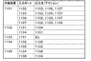
図7は、図6のブロードキャスト用経路に対応する制御情報(マッチ条件は省略)を示す図である。中継装置1102には、端末1101(1104)から受信したブロードキャストパケットを、中継装置1104(1101)に転送させる制御情報が設定される。一方、ブロードキャスト用経路の終端となった中継装置において端末の接続がない場合、その中継装置(例えば、中継装置1103)には、入力パケットの廃棄を行わせるため、出力アクションとして「なし」が設定される。
図7は、図6のブロードキャスト用経路に対応する制御情報(マッチ条件は省略)を示す図である。中継装置1102には、端末1101(1104)から受信したブロードキャストパケットを、中継装置1104(1101)に転送させる制御情報が設定される。一方、ブロードキャスト用経路の終端となった中継装置において端末の接続がない場合、その中継装置(例えば、中継装置1103)には、入力パケットの廃棄を行わせるため、出力アクションとして「なし」が設定される。
以上のようにして、中継装置からの制御情報の送信要求を受ける前に、ブロードキャスト用の制御情報の設定が完了する。
[ブロードキャスト用経路を用いたユニキャストパケットの転送]
また、本実施形態によれば、上記のようにして計算したブロードキャスト用経路を、宛先不明のユニキャストパケットの転送にも用いることができる。
また、本実施形態によれば、上記のようにして計算したブロードキャスト用経路を、宛先不明のユニキャストパケットの転送にも用いることができる。
図8~図10に、ブロードキャスト用経路を使用して宛先不明のユニキャストパケットを転送する例を示す。図8に示すように、端末1108がユニキャストパケットを送信すると、このパケットを受信した中継装置1105は、既存の制御情報(ブロードキャスト用の制御情報)のマッチ条件と照合を行う。
この時点では、中継装置1105は、ブロードキャスト用の制御情報のみを保持しているため、中継装置1105は、図9に示すように、制御装置200に対して、前記ユニキャストパケットの受信を通知する。
前記通知を受けたユニキャストパケットの宛先を学習済みである場合、制御装置200は、特許文献1等に記載された方法と同様の方法を用いてユニキャスト用の経路計算と、制御情報の生成、送信を行う。
一方、前記通知を受けたユニキャストパケットの宛先が不明である場合、制御装置200は、図10に示すように、ブロードキャスト配信経路を使用して、このユニキャストパケットをすべての端末に送信する。具体的には、図10の中継装置1105において、前記ユニキャストパケットの所定にフィールドにブロードキャストパケットであることを示すフラグ等を埋め込んでから転送させることにより、各中継装置にブロードキャストパケットとして転送させる。そして、経路の終点の中継装置のうち、端末1106、1107が接続された中継装置1101において、前記フラグを除去してから端末1106、1107に転送する処理を行わせる。
以上のように、本実施形態によれば、ネットワークを構成する中継装置1101~1105に対して予めブロードキャストパケットの転送用の制御情報が送信される。この結果、中継装置1101~1105と制御装置200間のブロードキャストパケット用の制御情報の授受と、制御装置200における前記制御情報の送信要求に対する応答処理の削減が実現される。
また、本実施形態によれば、宛先不明のユニキャストパケットについても、予め設定したブロードキャスト用経路を用いて転送することができる。具体的には、制御装置200が任意の中継装置にパケットヘッダの書き換えと復元を指示するだけで、必要な転送が実現される。なお、図8~図10に示した例では、制御装置200に対し、宛先不明のユニキャストパケットの受信を通知してから、ブロードキャストを行うものとして説明したが、予め宛先不明のユニキャストパケットをブロードキャスト経路(制御装置200を含む)で配信する制御情報を設定しておき、後から必要な制御情報の設定を行う方法も採用可能である。
以上、本発明の実施形態を説明したが、本発明は、上記した実施形態に限定されるものではなく、本発明の基本的技術的思想を逸脱しない範囲で、更なる変形・置換・調整を加えることができる。例えば、上記した実施形態で用いたネットワーク構成や、スイッチ及び端末の数はあくまで一例であり、その数に制約は無い。
また、上記した実施形態では、ブロードキャストパケットの転送制御を行う例を挙げて説明したが、ブロードキャストパケット以外のパケットを制御対象パケットとすることもできる。例えば、マルチキャストパケット等の転送にも本発明を適用することができる。
(付記)
本発明は、以下の形態を採ることが可能である。
本発明は、以下の形態を採ることが可能である。
[形態1]
前記第1の視点に記載の制御装置のとおり。
前記第1の視点に記載の制御装置のとおり。
[形態2]
前記制御装置は、前記制御対象の中継装置から宛先不明のユニキャストパケットの受信通知を受けた場合、前記ブロードキャスト用経路上の中継装置に、前記ユニキャストパケットを前記ブロードキャスト用経路に沿って転送させることができる。
前記制御装置は、前記制御対象の中継装置から宛先不明のユニキャストパケットの受信通知を受けた場合、前記ブロードキャスト用経路上の中継装置に、前記ユニキャストパケットを前記ブロードキャスト用経路に沿って転送させることができる。
[形態3]
前記制御装置は、前記ブロードキャスト用経路の上流側の中継装置に、前記ブロードキャストであるか、ユニキャストであるかを識別する情報をパケットヘッダに埋め込む処理を実行させる制御情報を設定し、
前記ブロードキャスト用経路の下流側の中継装置に、前記パケットヘッダに埋め込まれたブロードキャストであるか、ユニキャストであるかを識別する情報が埋め込まれたパケットを復元する処理を行わせる制御情報を設定することができる。
前記制御装置は、前記ブロードキャスト用経路の上流側の中継装置に、前記ブロードキャストであるか、ユニキャストであるかを識別する情報をパケットヘッダに埋め込む処理を実行させる制御情報を設定し、
前記ブロードキャスト用経路の下流側の中継装置に、前記パケットヘッダに埋め込まれたブロードキャストであるか、ユニキャストであるかを識別する情報が埋め込まれたパケットを復元する処理を行わせる制御情報を設定することができる。
[形態4]
前記制御装置は、ブロードキャスト対象パケットのうち、学習が必要な所定のプロトコルのパケットについては、自装置にもパケットを転送させる制御情報を設定し、受信したパケットを用いて学習を行うことができる。
前記制御装置は、ブロードキャスト対象パケットのうち、学習が必要な所定のプロトコルのパケットについては、自装置にもパケットを転送させる制御情報を設定し、受信したパケットを用いて学習を行うことができる。
[形態5]
前記第2の視点に記載の通信システムのとおり。
前記第2の視点に記載の通信システムのとおり。
[形態6]
前記第3の視点に記載の通信方法のとおり。
前記第3の視点に記載の通信方法のとおり。
[形態7]
前記第4の視点に記載のプログラムのとおり。
前記第4の視点に記載のプログラムのとおり。
なお、上記の特許文献および非特許文献の各開示を、本書に引用をもって繰り込むものとする。本発明の全開示(請求の範囲を含む)の枠内において、さらにその基本的技術思想に基づいて、実施形態ないし実施例の変更・調整が可能である。また、本発明の請求の範囲の枠内において種々の開示要素(各請求項の各要素、各実施形態ないし実施例の各要素、各図面の各要素等を含む)の多様な組み合わせ、ないし選択が可能である。すなわち、本発明は、請求の範囲を含む全開示、技術的思想にしたがって当業者であればなし得るであろう各種変形、修正を含むことは勿論である。特に、本書に記載した数値範囲については、当該範囲内に含まれる任意の数値ないし小範囲が、別段の記載のない場合でも具体的に記載されているものと解釈されるべきである。
10 ネットワーク
21、202 トポロジ情報取得部
22、207 ブロードキャスト用経路探索部(BC用経路探索部)
23 制御コマンド生成部
24 通信部
20、200 制御装置
201 中継装置通信部
203 トポロジ情報管理部
204 ユニキャスト用経路探索部
205 ユニキャスト用経路制御コマンド生成部
206 ブロードキャスト用経路探索部(BC用経路探索部)
207 ブロードキャスト用経路制御コマンド生成部(BC用経路制御コマンド生成部)
208 トランク制御コマンド生成部
1101~1105 中継装置
1106~1108 端末
21、202 トポロジ情報取得部
22、207 ブロードキャスト用経路探索部(BC用経路探索部)
23 制御コマンド生成部
24 通信部
20、200 制御装置
201 中継装置通信部
203 トポロジ情報管理部
204 ユニキャスト用経路探索部
205 ユニキャスト用経路制御コマンド生成部
206 ブロードキャスト用経路探索部(BC用経路探索部)
207 ブロードキャスト用経路制御コマンド生成部(BC用経路制御コマンド生成部)
208 トランク制御コマンド生成部
1101~1105 中継装置
1106~1108 端末
Claims (8)
- 制御対象の中継装置によって構成されるネットワークのトポロジを取得するトポロジ取得部と、
前記取得したネットワークトポロジと、前記ネットワークに接続する外部ノードの情報と、に基づいて、任意の外部ノードを始点とするブロードキャスト用経路を計算するブロードキャスト用経路探索部と、
前記計算したブロードキャスト用経路上の中継装置に、前記ブロードキャスト用経路に沿ったパケット転送を行わせる制御情報を生成する制御コマンド生成部と、
前記ブロードキャスト用経路上の中継装置に、前記生成した制御情報を設定する通信部と、を備えた制御装置。 - 前記制御対象の中継装置から宛先不明のユニキャストパケットの受信通知を受けた場合、前記ブロードキャスト用経路上の中継装置に、前記ユニキャストパケットを前記ブロードキャスト用経路に沿って転送させる請求項1の制御装置。
- 前記ブロードキャスト用経路の上流側の中継装置に、前記ブロードキャストであるか、ユニキャストであるかを識別する情報をパケットヘッダに埋め込む処理を実行させる制御情報を設定し、
前記ブロードキャスト用経路の下流側の中継装置に、前記パケットヘッダに埋め込まれたブロードキャストであるか、ユニキャストであるかを識別する情報が埋め込まれたパケットを復元する処理を行わせる制御情報を設定する請求項1または2の制御装置。 - ブロードキャスト対象パケットのうち、学習が必要な所定のプロトコルのパケットについては、自装置にもパケットを転送させる制御情報を設定し、受信したパケットを用いて学習を行う請求項1から3いずれか一の制御装置。
- 制御対象の中継装置によって構成されるネットワークのトポロジを取得するトポロジ取得部と、前記取得したネットワークトポロジと、前記ネットワークに接続する外部ノードの情報と、に基づいて、任意の外部ノードを始点とするブロードキャスト用経路を計算するブロードキャスト用経路探索部と、前記計算したブロードキャスト用経路上の中継装置に、前記ブロードキャスト用経路に沿ったパケット転送を行わせる制御情報を生成する制御コマンド生成部と、前記ブロードキャスト用経路上の中継装置に、前記生成した制御情報を設定する通信部と、を備えた制御装置と、
前記制御装置から設定された制御情報に基づいてパケットを処理する中継装置と、を含む通信システム。 - 中継装置群を制御する制御装置が、
前記中継装置群によって構成されるネットワークのトポロジを取得するステップと、
前記取得したネットワークトポロジと、前記ネットワークに接続する外部ノードの情報と、に基づいて、任意の外部ノードを始点とするブロードキャスト用経路を計算するステップと、
前記計算したブロードキャスト用経路上の中継装置に、前記ブロードキャスト用経路に沿ったパケット転送を行わせる制御情報を生成するステップと、
前記ブロードキャスト用経路上の中継装置に、前記生成した制御情報を設定するステップと、
を含む通信方法。 - 中継装置群を制御する制御装置に搭載されたコンピュータに、
前記中継装置群によって構成されるネットワークのトポロジを取得する処理と、
前記取得したネットワークトポロジと、前記ネットワークに接続する外部ノードの情報と、に基づいて、任意の外部ノードを始点とするブロードキャスト用経路を計算する処理と、
前記計算したブロードキャスト用経路上の中継装置に、前記ブロードキャスト用経路に沿ったパケット転送を行わせる制御情報を生成する処理と、
前記ブロードキャスト用経路上の中継装置に、前記生成した制御情報を設定する処理と、
を実行させるプログラム。 - 中継装置群を制御する制御装置に搭載されたコンピュータに、
前記中継装置群によって構成されるネットワークのトポロジを取得する処理と、
前記取得したネットワークトポロジと、前記ネットワークに接続する外部ノードの情報と、に基づいて、任意の外部ノードを始点とするブロードキャスト用経路を計算する処理と、
前記計算したブロードキャスト用経路上の中継装置に、前記ブロードキャスト用経路に沿ったパケット転送を行わせる制御情報を生成する処理と、
前記ブロードキャスト用経路上の中継装置に、前記生成した制御情報を設定する処理と、
を実行させるプログラムを格納した記録媒体。
Priority Applications (3)
| Application Number | Priority Date | Filing Date | Title |
|---|---|---|---|
| US14/414,642 US20150215203A1 (en) | 2012-07-26 | 2013-07-26 | Control apparatus, communication system, communication method, and program |
| EP13822594.1A EP2879335A4 (en) | 2012-07-26 | 2013-07-26 | CONTROL DEVICE, COMMUNICATION SYSTEM, COMMUNICATION PROCESS AND PROGRAM |
| CN201380038719.8A CN104509045A (zh) | 2012-07-26 | 2013-07-26 | 控制装置、通信系统、通信方法和程序 |
Applications Claiming Priority (2)
| Application Number | Priority Date | Filing Date | Title |
|---|---|---|---|
| JP2012-165451 | 2012-07-26 | ||
| JP2012165451A JP2014027443A (ja) | 2012-07-26 | 2012-07-26 | 制御装置、通信システム、通信方法及びプログラム |
Publications (1)
| Publication Number | Publication Date |
|---|---|
| WO2014017631A1 true WO2014017631A1 (ja) | 2014-01-30 |
Family
ID=49997436
Family Applications (1)
| Application Number | Title | Priority Date | Filing Date |
|---|---|---|---|
| PCT/JP2013/070320 WO2014017631A1 (ja) | 2012-07-26 | 2013-07-26 | 制御装置、通信システム、通信方法及びプログラム |
Country Status (5)
| Country | Link |
|---|---|
| US (1) | US20150215203A1 (ja) |
| EP (1) | EP2879335A4 (ja) |
| JP (1) | JP2014027443A (ja) |
| CN (1) | CN104509045A (ja) |
| WO (1) | WO2014017631A1 (ja) |
Families Citing this family (8)
| Publication number | Priority date | Publication date | Assignee | Title |
|---|---|---|---|---|
| JP2015192237A (ja) * | 2014-03-27 | 2015-11-02 | 富士通株式会社 | 伝送装置、伝送システム、伝送方法及び伝送プログラム |
| US9413646B2 (en) * | 2014-08-25 | 2016-08-09 | Nec Corporation | Path selection in hybrid networks |
| JP2016181819A (ja) | 2015-03-24 | 2016-10-13 | 富士通株式会社 | ネットワークの制御装置及び制御方法、並びに、ネットワークスイッチ |
| JP6606919B2 (ja) | 2015-08-25 | 2019-11-20 | 富士通株式会社 | フロースイッチ、コントローラ、及び、中継装置 |
| CN107204924B (zh) * | 2016-03-18 | 2020-09-25 | 华为技术有限公司 | 链路发现方法及装置 |
| TWI607639B (zh) * | 2016-06-27 | 2017-12-01 | Chunghwa Telecom Co Ltd | SDN sharing tree multicast streaming system and method |
| CN108449776B (zh) * | 2018-02-27 | 2023-09-05 | 深圳市亚特联科技有限公司 | 网络路径规划方法、节点设备及计算机存储介质 |
| CN110719178A (zh) * | 2018-07-11 | 2020-01-21 | 富士通株式会社 | 网络拓扑获取方法及其装置 |
Citations (5)
| Publication number | Priority date | Publication date | Assignee | Title |
|---|---|---|---|---|
| WO2005048540A1 (ja) * | 2003-11-17 | 2005-05-26 | Nec Corporation | 通信システム及び通信方法 |
| JP2008141468A (ja) * | 2006-12-01 | 2008-06-19 | Mitsubishi Electric Corp | 伝送装置 |
| JP2008199130A (ja) * | 2007-02-08 | 2008-08-28 | Furukawa Electric Co Ltd:The | ネットワーク中継方法、ネットワーク要素およびネットワーク中継システム |
| JP2010166629A (ja) * | 2010-05-07 | 2010-07-29 | Hitachi Ltd | ネットワーク中継装置及びその制御方法 |
| JP2011101245A (ja) | 2009-11-06 | 2011-05-19 | Nec Corp | 通信システム、経路制御装置、経路制御方法および経路制御用プログラム |
Family Cites Families (14)
| Publication number | Priority date | Publication date | Assignee | Title |
|---|---|---|---|---|
| US6831895B1 (en) * | 1999-05-19 | 2004-12-14 | Lucent Technologies Inc. | Methods and devices for relieving congestion in hop-by-hop routed packet networks |
| KR100411251B1 (ko) * | 2001-11-28 | 2003-12-18 | 한국전자통신연구원 | 제한조건을 만족하는 다중 경로 배정방법 |
| US7145871B2 (en) * | 2002-03-02 | 2006-12-05 | At&T Corp. | Automatic router configuration based on traffic and service level agreements |
| US7289456B2 (en) * | 2002-04-08 | 2007-10-30 | Telcordia Technologies, Inc. | Determining and provisioning paths within a network of communication elements |
| US7571463B1 (en) * | 2003-01-24 | 2009-08-04 | Nortel Networks Limited | Method an apparatus for providing a scalable and secure network without point to point associations |
| JPWO2004073269A1 (ja) * | 2003-02-13 | 2006-06-01 | 富士通株式会社 | 伝送システム,配信経路制御装置,負荷情報収集装置および配信経路制御方法 |
| FR2866497B1 (fr) * | 2004-02-18 | 2006-08-18 | Cit Alcatel | Controleur de bande passante, reseau et procede de gestion de sous-reseau ip |
| JP4527447B2 (ja) * | 2004-06-10 | 2010-08-18 | 株式会社日立製作所 | ネットワーク中継装置及びその制御方法 |
| CN103220748B (zh) * | 2005-07-21 | 2017-04-12 | 发尔泰公司 | 用于使任意互连的网状网络有效操作的方法及系统 |
| US7398438B2 (en) * | 2006-03-30 | 2008-07-08 | Lucent Technologies Inc. | Method and apparatus for improved routing in connectionless networks |
| US8811224B2 (en) * | 2006-05-30 | 2014-08-19 | McAfee Ireland Holdings, Limited | Method and system for determining physical connectivity in a dynamic network |
| US9185166B2 (en) * | 2012-02-28 | 2015-11-10 | International Business Machines Corporation | Disjoint multi-pathing for a data center network |
| US9094285B2 (en) * | 2013-01-25 | 2015-07-28 | Argela Yazilim ve Bilisim Teknolojileri San. ve Tic. A.S. | Automatic discovery of multiple controllers in Software Defined Networks (SDNs) |
| US9008080B1 (en) * | 2013-02-25 | 2015-04-14 | Big Switch Networks, Inc. | Systems and methods for controlling switches to monitor network traffic |
-
2012
- 2012-07-26 JP JP2012165451A patent/JP2014027443A/ja active Pending
-
2013
- 2013-07-26 US US14/414,642 patent/US20150215203A1/en not_active Abandoned
- 2013-07-26 EP EP13822594.1A patent/EP2879335A4/en not_active Withdrawn
- 2013-07-26 CN CN201380038719.8A patent/CN104509045A/zh active Pending
- 2013-07-26 WO PCT/JP2013/070320 patent/WO2014017631A1/ja active Application Filing
Patent Citations (5)
| Publication number | Priority date | Publication date | Assignee | Title |
|---|---|---|---|---|
| WO2005048540A1 (ja) * | 2003-11-17 | 2005-05-26 | Nec Corporation | 通信システム及び通信方法 |
| JP2008141468A (ja) * | 2006-12-01 | 2008-06-19 | Mitsubishi Electric Corp | 伝送装置 |
| JP2008199130A (ja) * | 2007-02-08 | 2008-08-28 | Furukawa Electric Co Ltd:The | ネットワーク中継方法、ネットワーク要素およびネットワーク中継システム |
| JP2011101245A (ja) | 2009-11-06 | 2011-05-19 | Nec Corp | 通信システム、経路制御装置、経路制御方法および経路制御用プログラム |
| JP2010166629A (ja) * | 2010-05-07 | 2010-07-29 | Hitachi Ltd | ネットワーク中継装置及びその制御方法 |
Non-Patent Citations (3)
| Title |
|---|
| NICK MCKEOWN, OPENFLOW: ENABLING INNOVATION IN CAMPUS NETWORKS, 13 July 2012 (2012-07-13), Retrieved from the Internet <URL:<URL:http://www.openflow.org/documents/openflow-wp-latest.pdf>> |
| OPENFLOW SWITCH SPECIFICATION, VERSION 1.1.0 IMPLEMENTED (WIRE PROTOCOL 0X02, 13 July 2012 (2012-07-13), Retrieved from the Internet <URL:<URL:http://www.openflow.org/documents/openflow-spec-vl.I.O.pdf>> |
| See also references of EP2879335A4 |
Also Published As
| Publication number | Publication date |
|---|---|
| EP2879335A1 (en) | 2015-06-03 |
| EP2879335A4 (en) | 2016-03-16 |
| CN104509045A (zh) | 2015-04-08 |
| US20150215203A1 (en) | 2015-07-30 |
| JP2014027443A (ja) | 2014-02-06 |
Similar Documents
| Publication | Publication Date | Title |
|---|---|---|
| WO2014017631A1 (ja) | 制御装置、通信システム、通信方法及びプログラム | |
| US9692650B2 (en) | Control apparatus, communication system, communication method, and program | |
| WO2011108205A1 (ja) | 通信システム、経路制御装置、パケット転送装置および経路制御方法 | |
| WO2011155510A1 (ja) | 通信システム、制御装置、パケットキャプチャ方法およびプログラム | |
| JP5644948B2 (ja) | パケット転送システム、制御装置、パケット転送方法およびプログラム | |
| US10069648B2 (en) | Communication system, control apparatus, communication control method and program | |
| JP6070700B2 (ja) | パケット転送システム、制御装置、パケット転送方法及びプログラム | |
| WO2011118574A1 (ja) | 通信システム、制御装置、遅延測定方法およびプログラム | |
| WO2014129624A1 (ja) | 制御装置、通信システム、経路切替方法及びプログラム | |
| WO2012081721A1 (ja) | 通信システム、ノード、パケット転送方法およびプログラム | |
| WO2014175423A1 (ja) | 通信ノード、通信システム、パケット処理方法及びプログラム | |
| JP6206493B2 (ja) | 制御装置、通信システム、中継装置の制御方法及びプログラム | |
| US20160050081A1 (en) | Control apparatus, communication system, communication node control method, and program | |
| WO2015045275A1 (ja) | 制御装置、ネットワークシステム、パケット転送制御方法、制御装置用プログラム | |
| US20160094357A1 (en) | Control apparatus, computer system, communication control method, and program | |
| JP5854488B2 (ja) | 通信システム、制御装置、処理規則の設定方法およびプログラム | |
| US20150372900A1 (en) | Communication system, control apparatus, communication control method, and program | |
| JP6314970B2 (ja) | 通信システム、制御装置、通信方法およびプログラム | |
| WO2015087947A1 (ja) | 通信システム、通信ノード、制御装置、通信制御方法及びプログラム | |
| JP2016139908A (ja) | 通信システム、通信ノード、制御装置、通信制御方法、及び、プログラム |
Legal Events
| Date | Code | Title | Description |
|---|---|---|---|
| 121 | Ep: the epo has been informed by wipo that ep was designated in this application |
Ref document number: 13822594 Country of ref document: EP Kind code of ref document: A1 |
|
| REEP | Request for entry into the european phase |
Ref document number: 2013822594 Country of ref document: EP |
|
| WWE | Wipo information: entry into national phase |
Ref document number: 2013822594 Country of ref document: EP |
|
| WWE | Wipo information: entry into national phase |
Ref document number: 14414642 Country of ref document: US |
|
| NENP | Non-entry into the national phase |
Ref country code: DE |