WO2014017631A1 - Dispositif de contrôle, système de communication, procédé de communication, et programme - Google Patents
Dispositif de contrôle, système de communication, procédé de communication, et programme Download PDFInfo
- Publication number
- WO2014017631A1 WO2014017631A1 PCT/JP2013/070320 JP2013070320W WO2014017631A1 WO 2014017631 A1 WO2014017631 A1 WO 2014017631A1 JP 2013070320 W JP2013070320 W JP 2013070320W WO 2014017631 A1 WO2014017631 A1 WO 2014017631A1
- Authority
- WO
- WIPO (PCT)
- Prior art keywords
- broadcast
- relay device
- route
- control information
- network
- Prior art date
Links
Images


Classifications
-
- H—ELECTRICITY
- H04—ELECTRIC COMMUNICATION TECHNIQUE
- H04L—TRANSMISSION OF DIGITAL INFORMATION, e.g. TELEGRAPHIC COMMUNICATION
- H04L45/00—Routing or path finding of packets in data switching networks
- H04L45/74—Address processing for routing
-
- H—ELECTRICITY
- H04—ELECTRIC COMMUNICATION TECHNIQUE
- H04L—TRANSMISSION OF DIGITAL INFORMATION, e.g. TELEGRAPHIC COMMUNICATION
- H04L45/00—Routing or path finding of packets in data switching networks
- H04L45/16—Multipoint routing
-
- H—ELECTRICITY
- H04—ELECTRIC COMMUNICATION TECHNIQUE
- H04L—TRANSMISSION OF DIGITAL INFORMATION, e.g. TELEGRAPHIC COMMUNICATION
- H04L45/00—Routing or path finding of packets in data switching networks
- H04L45/02—Topology update or discovery
-
- H—ELECTRICITY
- H04—ELECTRIC COMMUNICATION TECHNIQUE
- H04L—TRANSMISSION OF DIGITAL INFORMATION, e.g. TELEGRAPHIC COMMUNICATION
- H04L45/00—Routing or path finding of packets in data switching networks
- H04L45/46—Cluster building
-
- H—ELECTRICITY
- H04—ELECTRIC COMMUNICATION TECHNIQUE
- H04L—TRANSMISSION OF DIGITAL INFORMATION, e.g. TELEGRAPHIC COMMUNICATION
- H04L69/00—Network arrangements, protocols or services independent of the application payload and not provided for in the other groups of this subclass
- H04L69/22—Parsing or analysis of headers
-
- H—ELECTRICITY
- H04—ELECTRIC COMMUNICATION TECHNIQUE
- H04L—TRANSMISSION OF DIGITAL INFORMATION, e.g. TELEGRAPHIC COMMUNICATION
- H04L45/00—Routing or path finding of packets in data switching networks
- H04L45/64—Routing or path finding of packets in data switching networks using an overlay routing layer
Definitions
- the present invention relates to a control device, a communication system, a communication method, and a program, and more particularly, to a control device, a communication system, a communication method, and a program that centrally control a switch to be controlled.
- Non-Patent Documents 1 and 2 OpenFlow captures communication as an end-to-end flow and performs path control, failure recovery, load balancing, and optimization on a per-flow basis.
- the OpenFlow switch specified in Non-Patent Document 2 includes a secure channel for communication with the OpenFlow controller, and operates according to a flow table that is appropriately added or rewritten from the OpenFlow controller. For each flow, a set of match conditions (Match Fields), flow statistical information (Counters), and instructions (Instructions) that define processing contents are defined for each flow (non-patented). (Refer to “4.1 Flow Table” in Document 2).
- the OpenFlow switch searches the flow table for an entry having a matching condition (see “4.3 Match Fields” in Non-Patent Document 2) that matches the header information of the received packet. If an entry that matches the received packet is found as a result of the search, the OpenFlow switch updates the flow statistical information (counter) and processes the processing (designated) in the instruction field of the entry for the received packet. Perform packet transmission, flooding, discard, etc. from the port. On the other hand, if no entry matching the received packet is found as a result of the search, the OpenFlow switch sends an entry setting request to the OpenFlow controller via the secure channel, that is, a control for processing the received packet. An information transmission request (Packet-In message) is transmitted. The OpenFlow switch receives a flow entry whose processing content is defined and updates the flow table. As described above, the OpenFlow switch performs packet transfer using the entry stored in the flow table as control information.
- a matching condition see “4.3 Match Fields” in Non-Patent Document 2
- the OpenFlow switch updates the flow statistical information
- Patent Document 1 discloses a method for reducing the load on the path control device corresponding to the open flow controller by making the timeout value of the flow entry different for each section of the packet communication path.
- control devices that are centrally controlled by control devices such as “Open Flow Switch” in Non-Patent Documents 1 and 2 and “Flow Switch” in Patent Document 1 are collectively referred to as “relay devices”.
- devices that centrally control switches such as “Open Flow Controller” in Non-Patent Documents 1 and 2 and “Route Control Device” in Patent Document 1 are referred to as “control devices”.
- Non-Patent Documents 1 and 2 and Patent Document 1 when a packet that does not hold the corresponding flow entry is received, the relay device is addressed to the control device and the flow entry for processing this packet is Request settings.
- the relay device When a large amount of packets, especially packets such as broadcast packets and multicast packets, flow into the relay device, not only the relay device but also other relay devices issue a large number of flow entry setting requests to the control device. .
- the network load between the relay device and the control device and the processing load of the control device in response to the flow entry setting request increase.
- An object of the present invention is to provide a control device, a communication system, a communication method, and a program capable of reducing the network load between the relay device and the control device and the processing load of the control device due to the broadcast in the centralized control network. .
- a broadcast route search unit that calculates a broadcast route starting from an arbitrary external node, and control information that causes a relay device on the calculated broadcast route to perform packet transfer along the broadcast route are generated.
- a control device is provided that includes a control command generation unit and a communication unit that sets the generated control information in a relay device on the broadcast route.
- a broadcast route search unit that calculates a broadcast route starting from an arbitrary external node, and control information that causes a relay device on the calculated broadcast route to perform packet transfer along the broadcast route are generated.
- a control device including a control command generation unit, a communication unit that sets the generated control information in a relay device on the broadcast route, and processes a packet based on the control information set by the control device.
- a control device that controls a relay device group acquires a topology of a network constituted by the relay device group, the acquired network topology, and an external node connected to the network. And a step of calculating a broadcast route starting from an arbitrary external node based on the information, and control information for causing the relay apparatus on the calculated broadcast route to perform packet transfer along the broadcast route And a step of setting the generated control information in a relay device on the broadcast route.
- This method is linked to a specific machine called a control device that controls a group of relay devices.
- This program can be recorded on a computer-readable (non-transient) storage medium. That is, the present invention can be embodied as a computer program product.
- the present invention it is possible to reduce the network load between the relay device and the control device and the processing load of the control device due to the broadcast in the centralized control network.
- FIG. 5 is an example of a flow entry corresponding to the broadcast path of FIG. 4.
- FIG. 3 is a diagram illustrating a broadcast route starting from the relay apparatus 1102 in FIG. 2. 7 is an example of a flow entry corresponding to the broadcast path in FIG. 6. It is a figure for demonstrating transfer of the unicast packet using the path
- FIG. 9 is a continuation diagram of FIG. 8.
- FIG. 10 is a continuation diagram of FIG. 9.
- a topology information acquisition unit 21 that acquires the topology of a network 10 constituted by controlled relay devices, the acquired network topology, and the network
- the broadcast route search unit 22 that calculates a broadcast route starting from an arbitrary external node based on the information of the connected external node, and the broadcast route to the relay device on the calculated broadcast route.
- a control command generator 23 that generates control information for performing packet transfer along the communication path, and a communication unit 24 that sets the generated control information in a relay device on a broadcast route. realizable.
- control device 20 calculates a broadcast route starting from an arbitrary external node (see FIGS. 4 and 6), and a relay device on these broadcast routes. Control information for performing packet transfer along the broadcast route is set.
- control information is set before the control information is set from the relay device to the control device (corresponding to the flow entry described above), so the relay device indicated by the broken line in FIG.
- the network load between the control devices and the processing load of the control devices can be reduced.
- FIG. 2 is a diagram illustrating the configuration of the communication system according to the first embodiment of this invention.
- relay apparatuses 1101 to 1105 that perform packet processing using control information set by the control apparatus 200, and terminals 1106 to 1108 that are connected to and communicate with any of these relay apparatuses 1101 to 1105;
- a configuration including the control device 200 is shown.
- the relay devices 1101 to 1105 are connected to the control device 200 via a control interface indicated by a broken line in the figure.
- the terminal 1106 and the terminal 1107 are connected to the relay apparatus 1101 via the data transfer interface indicated by the solid line in the figure.
- the terminal 1108 is connected to the relay apparatus 1105 via the data transfer interface.
- the relay device 1101 is connected to the relay device 1102, the relay device 1103, the relay device 1104, and the relay device 1105 via a data transfer interface.
- the relay device 1102 is connected to the relay device 1101 and the relay device 1104 via a data transfer interface.
- the relay device 1103 is connected to the relay device 1101 and the relay device 1105 via a data transfer interface.
- the relay device 1104 is connected to the relay device 1101, the relay device 1102, and the relay device 1105 via the data transfer interface.
- the relay device 1105 is connected to the relay device 1101, the relay device 1103, and the relay device 1104 via a data transfer interface.
- Non-Patent Document 2 open flow switches ordered in accordance with the specifications of Non-Patent Document 2 can be cited.
- CLI command line interface
- FIG. 3 is a diagram showing the configuration of the control device according to the first embodiment of the present invention.
- a relay device communication unit 201 that performs control communication with the relay devices 1101 to 1105
- a topology information acquisition unit 202 that acquires a topology between the relay devices 1101 to 1105 via the relay device communication unit 201.
- the topology information management unit 203 that stores the topology, the unicast route search unit 204 that searches for a unicast route, and the relay devices 1101 to 1105 on the route searched by the unicast route search unit 204
- a control information to be transmitted and a control command to transmit this control information are generated and transmitted via the relay apparatus communication unit 201, and for unicast path control command generation unit 205, and for broadcast (hereinafter also referred to as “BC”).
- the BC route search unit 206 that searches for a route, and the relay device 1 on the route searched by the BC route search unit 206 01 generates control information transmitted to the ⁇ 1105 and the control command to transmit this control information, configuration and a BC for route control command generating unit 207 to be transmitted via the relay device communication unit 201 is shown.
- the relay device communication unit 201 establishes a control session with the relay devices 1101 to 1105 and transmits / receives a control command.
- a control command an OpenFlow protocol control message described in Non-Patent Document 2 may be used. Communication may be performed using CLI via Telnet, SNMP (Simple Network Management Protocol), or the like.
- the topology information acquisition unit 202 acquires the topology between the relay apparatuses 1101 to 1105.
- Examples of the topology acquisition method include a method of sucking up adjacent relay device recognition information of the relay device.
- LLDP Link Layer Discovery Protocol
- the control device 200 performs control so that a packet including the ID and port number of the relay device is output from a specific port of the specific relay device, and receives the packet from the opposite relay device. It is also possible to adopt a method of performing inter-recognition.
- the Packet-Out message and the Packet-In message of Non-Patent Document 2 can be used.
- a network administrator and a method of setting in advance when the system is started up are also conceivable.
- the topology information management unit 203 manages the topology information acquired by the topology information acquisition unit 202 and provides the topology information to the unicast route search unit 204 and the BC route search unit 206.
- the unicast route search unit 204 calculates a route that passes through relay devices 1101 to 1105 between arbitrary terminals.
- a different route may be calculated for each relay device connected to the terminal, or a route tree having the relay device connected to the terminal as a starting point or an ending point may be calculated.
- the shortest route tree (the Dijkstra method is representative) can be used. These routes are not limited to a single route, and different routes may be used for each communication unit. In this calculation, calculation may be performed with all the relay devices as starting points or ending points.
- the unicast route control command generation unit 205 generates control information to be transmitted to the relay device on the unicast route calculated by the unicast route search unit 204 and a control command to transmit this control information. Then, the unicast route control command generation unit 205 transmits the generated control command to the relay device on the unicast route via the relay device communication unit 201.
- At least a destination address is set as the matching condition of the control information for unicast.
- a destination address an IP (Internet Protocol) address and a MAC (Media Access Control) address, a TCP / UDP (Transmission Control Protocol / User Datagram Protocol) port, or the like can be used. Further, the flow entry setting message of Non-Patent Document 2 can be used as this control command.
- BC route search unit 206 calculates a spanning tree path that can be distributed from the relay device connected to the terminal to at least all other relay devices connected to the terminal.
- this spanning tree path one or a plurality of paths may be calculated in the network.
- different global routes may be calculated for each relay device connected to the terminal. Examples of the route calculation method include a method for obtaining a minimum spanning tree (a prim method and a Kruskal method are representative). In this calculation, a relay device that is not connected to the terminal and is not at the end of the spanning tree is repeatedly excluded, so that a relay device that is not required between the relay devices connected to the terminal is removed. It may be excluded from the transfer path.
- the BC path control command generation unit 207 determines a match condition for identifying a packet that is permitted to be transferred on the broadcast distribution path.
- a packet whose transmission address is a broadcast address is set as a match condition.
- a packet having a leading bit (I / G bit) of 1 when transmitting the destination MAC address is designated.
- the BC route control command generation unit 207 also transmits control information including the match condition to be transmitted to the relay device on the broadcast route calculated by the BC route search unit 206 and control for transmitting this control information. Generate a command.
- the broadcast control information generated by the BC route control command generation unit 207 has a lower priority than the control information generated by the unicast route control command generation unit 205. As a result, among packets that do not meet the matching conditions of the unicast control information, packets that satisfy a predetermined condition can be broadcast. In addition, when there is a packet that is not desired to be transferred through the broadcast distribution route, control information for discarding a packet having a matching condition for identifying such a packet may be set.
- a flag (unicast / BC identification flag) or the like for distinguishing between them may be embedded.
- the header field may be restored by a relay device on the downstream side of the unicast route or the broadcast route (for example, a relay device connected to a terminal at the end of the route).
- an IP ToS (Type of Service) field, a VLAN Priority field, or the like can be considered.
- an arbitrary address in the header field may be degenerated and the flag described above may be put in the degenerated address.
- the destination MAC address is degenerated and the degenerated MAC address and the flag are put in the destination MAC address.
- the relay device on the exit side (for example, the relay device connected to the terminal at the end of the route) is caused to perform processing for restoring the original address from the degenerated address.
- VLAN Virtual Local Area Network
- the unicast VLAN ID is converted into a dedicated VLAN ID, a destination MAC address and an ID obtained by degenerating this VLAN ID are assigned, and this degenerated ID is set in the destination MAC address field. It is done.
- control information is set so that these packets are also transferred to the control device.
- the control device 200 can also perform address learning and the like. At this time, it is desirable to add determination information to an arbitrary field of these packets so that it can be identified that the broadcast has been completed.
- each unit (processing means) of the control device 200 shown in FIG. 2 can also be realized by a computer program that causes a computer constituting the control device 200 to execute the above-described processes using its hardware.
- the topology information acquisition unit 202 acquires the network topology at a predetermined timing such as the elapse of a fixed time or the addition of a new relay device.
- a predetermined timing such as the elapse of a fixed time or the addition of a new relay device.
- the topology is acquired between the relay apparatuses 1101 to 1105 shown in FIG.
- the BC route search unit 206 calculates a broadcast route from the topology information management unit 203 based on the topology shown in FIG. 2 and information on terminals connected to each relay device.
- FIG. 4 is a diagram showing a broadcast route starting from the relay device 1101 in FIG.
- links used as broadcast routes among links between relay devices are indicated by solid lines, and links not used as broadcast routes are indicated by dotted lines. Since the relay device 1101 is connected to the relay devices 1102 to 1105, a link directly connected to each relay device can be used as a broadcast route. On the other hand, the links of the dotted lines between the relay apparatuses 1102 to 1105 are removed from the broadcast route so that the route does not loop.
- the BC route control command generation unit 207 generates control information that causes the relay device on the calculated broadcast route to transfer a packet along the broadcast route, and transmits the control information to each relay device.
- the relay apparatus 1101 includes not only the relay apparatuses 1102 to 1105 but also the terminal 1107 (1106) as well as the terminal 1106 (1107) so that a certain terminal can broadcast to all other terminals.
- the control information for transferring the broadcast packet input from (1) is transmitted.
- control information for transferring the broadcast packet to the terminal 1108 is transmitted to the relay apparatus 1105.
- FIG. 5 is a diagram showing control information (match conditions are omitted) corresponding to the broadcast route of FIG.
- control information for transferring broadcast packets received from the terminal 1106 to the relay apparatuses 1102 to 1105 and the terminal 1107 is set in the relay apparatus 1101 corresponding to the start point of the broadcast path.
- these relay devices for example, the relay devices 1102, 1103, and 1104 cause the input packet to be discarded. “None” is set.
- FIG. 6 is a diagram showing a broadcast route starting from the relay device 1102 of FIG. Also in FIG. 6, links used as broadcast routes among links between relay devices are indicated by solid lines, and links not used as broadcast routes are indicated by dotted lines. Since the relay device 1102 is not directly connected to the relay devices 1103 and 1105, a route for transferring the packet to the relay device 1103 via the relay device 1101 and the relay device 1105 via the relay device 1104 is required. Also, in the example of FIG. 6, the link in the dotted line portion is excluded from the broadcast route so that the route does not loop.
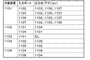
- FIG. 7 is a diagram showing control information (match conditions are omitted) corresponding to the broadcast path of FIG.
- Control information for transferring the broadcast packet received from the terminal 1101 (1104) to the relay device 1104 (1101) is set in the relay device 1102.
- the relay device for example, the relay device 1103
- the relay device is set to “none” as the output action in order to cause the relay device to discard the input packet. Is done.
- the broadcast route calculated as described above can also be used for transferring a unicast packet with an unknown destination.
- FIG. 8 to 10 show an example of transferring a unicast packet with an unknown destination using a broadcast route.
- the relay apparatus 1105 that has received this packet collates with a matching condition of existing control information (broadcast control information).
- the relay apparatus 1105 since the relay apparatus 1105 holds only the control information for broadcasting, the relay apparatus 1105 notifies the control apparatus 200 of the reception of the unicast packet as shown in FIG. .
- control device 200 uses the same method as described in Patent Document 1 and the like to calculate the unicast route and generate control information. , Send.
- the control device 200 transmits the unicast packet to all terminals using the broadcast distribution route as shown in FIG. Specifically, the relay apparatus 1105 in FIG. 10 causes each relay apparatus to transfer the broadcast packet as a broadcast packet by embedding a flag indicating that the packet is a broadcast packet in a predetermined field of the unicast packet. Then, among the relay devices at the end points of the route, the relay device 1101 to which the terminals 1106 and 1107 are connected causes the processing to be transferred to the terminals 1106 and 1107 after removing the flag.
- control information for transferring broadcast packets is transmitted in advance to the relay apparatuses 1101 to 1105 constituting the network.
- transmission / reception of broadcast packet control information between the relay apparatuses 1101 to 1105 and the control apparatus 200 and a reduction in response processing to the control information transmission request in the control apparatus 200 are realized.
- a unicast packet whose destination is unknown can be transferred using a preset broadcast route.
- the necessary transfer is realized only by the control device 200 instructing an arbitrary relay device to rewrite and restore the packet header.
- the control apparatus 200 has been described as performing broadcast after notifying the reception of the unicast packet with unknown destination. It is also possible to adopt a method of setting control information to be distributed through a broadcast route (including the control device 200) and setting necessary control information later.
- control device When the control device receives a reception notification of a unicast packet whose destination is unknown from the relay device to be controlled, the control device causes the relay device on the broadcast route to transfer the unicast packet along the broadcast route. be able to.
- the control device sets control information that causes the relay device on the upstream side of the broadcast path to execute processing for embedding information identifying whether the broadcast or unicast is in a packet header, Set control information that causes a relay device on the downstream side of the broadcast path to perform a process of restoring a packet in which information identifying whether it is broadcast or unicast embedded in the packet header is embedded be able to.
- the control device can set control information for transferring a packet of a predetermined protocol that needs to be learned among the broadcast target packets, and can learn using the received packet.
Abstract
La présente invention a pour objectif de réduire une charge de réseau entre des dispositifs relais et un dispositif de contrôle, et de réduire une charge de traitement du dispositif de réglage, lors de l'accompagnement d'une diffusion dans un réseau centralisé. Afin d'atteindre l'objectif visé, la présente invention se rapporte à un dispositif de contrôle qui comprend : un module d'acquisition de topologie, qui acquiert une topologie d'un réseau configuré par des dispositifs relais devant être contrôlés ; un module de recherche de chemin à utiliser pour une diffusion qui, sur la base de la topologie de réseau acquise et d'informations relatives à des nœuds externes qui sont connectés au réseau, calcule un chemin à utiliser pour une diffusion entre des nœuds externes arbitraires ; un module de génération d'instruction de commande, qui génère des données de commande qui sont utilisées pour commander à des dispositifs relais qui se trouvent sur le chemin à utiliser pour une diffusion qui a été calculé, d'exécuter un transfert de paquet le long du chemin à utiliser pour une diffusion ; et un module de communication, qui programme les données de commande qui ont été générées pour le dispositif relais, sur le chemin à utiliser pour une diffusion.
Priority Applications (3)
| Application Number | Priority Date | Filing Date | Title |
|---|---|---|---|
| CN201380038719.8A CN104509045A (zh) | 2012-07-26 | 2013-07-26 | 控制装置、通信系统、通信方法和程序 |
| EP13822594.1A EP2879335A4 (fr) | 2012-07-26 | 2013-07-26 | Dispositif de contrôle, système de communication, procédé de communication, et programme |
| US14/414,642 US20150215203A1 (en) | 2012-07-26 | 2013-07-26 | Control apparatus, communication system, communication method, and program |
Applications Claiming Priority (2)
| Application Number | Priority Date | Filing Date | Title |
|---|---|---|---|
| JP2012-165451 | 2012-07-26 | ||
| JP2012165451A JP2014027443A (ja) | 2012-07-26 | 2012-07-26 | 制御装置、通信システム、通信方法及びプログラム |
Publications (1)
| Publication Number | Publication Date |
|---|---|
| WO2014017631A1 true WO2014017631A1 (fr) | 2014-01-30 |
Family
ID=49997436
Family Applications (1)
| Application Number | Title | Priority Date | Filing Date |
|---|---|---|---|
| PCT/JP2013/070320 WO2014017631A1 (fr) | 2012-07-26 | 2013-07-26 | Dispositif de contrôle, système de communication, procédé de communication, et programme |
Country Status (5)
| Country | Link |
|---|---|
| US (1) | US20150215203A1 (fr) |
| EP (1) | EP2879335A4 (fr) |
| JP (1) | JP2014027443A (fr) |
| CN (1) | CN104509045A (fr) |
| WO (1) | WO2014017631A1 (fr) |
Families Citing this family (8)
| Publication number | Priority date | Publication date | Assignee | Title |
|---|---|---|---|---|
| JP2015192237A (ja) * | 2014-03-27 | 2015-11-02 | 富士通株式会社 | 伝送装置、伝送システム、伝送方法及び伝送プログラム |
| US9413646B2 (en) * | 2014-08-25 | 2016-08-09 | Nec Corporation | Path selection in hybrid networks |
| JP2016181819A (ja) | 2015-03-24 | 2016-10-13 | 富士通株式会社 | ネットワークの制御装置及び制御方法、並びに、ネットワークスイッチ |
| JP6606919B2 (ja) | 2015-08-25 | 2019-11-20 | 富士通株式会社 | フロースイッチ、コントローラ、及び、中継装置 |
| CN107204924B (zh) * | 2016-03-18 | 2020-09-25 | 华为技术有限公司 | 链路发现方法及装置 |
| TWI607639B (zh) * | 2016-06-27 | 2017-12-01 | Chunghwa Telecom Co Ltd | SDN sharing tree multicast streaming system and method |
| CN108449776B (zh) * | 2018-02-27 | 2023-09-05 | 深圳市亚特联科技有限公司 | 网络路径规划方法、节点设备及计算机存储介质 |
| CN110719178A (zh) * | 2018-07-11 | 2020-01-21 | 富士通株式会社 | 网络拓扑获取方法及其装置 |
Citations (5)
| Publication number | Priority date | Publication date | Assignee | Title |
|---|---|---|---|---|
| WO2005048540A1 (fr) * | 2003-11-17 | 2005-05-26 | Nec Corporation | Systeme de communications et procede de communications associes |
| JP2008141468A (ja) * | 2006-12-01 | 2008-06-19 | Mitsubishi Electric Corp | 伝送装置 |
| JP2008199130A (ja) * | 2007-02-08 | 2008-08-28 | Furukawa Electric Co Ltd:The | ネットワーク中継方法、ネットワーク要素およびネットワーク中継システム |
| JP2010166629A (ja) * | 2010-05-07 | 2010-07-29 | Hitachi Ltd | ネットワーク中継装置及びその制御方法 |
| JP2011101245A (ja) | 2009-11-06 | 2011-05-19 | Nec Corp | 通信システム、経路制御装置、経路制御方法および経路制御用プログラム |
Family Cites Families (14)
| Publication number | Priority date | Publication date | Assignee | Title |
|---|---|---|---|---|
| US6831895B1 (en) * | 1999-05-19 | 2004-12-14 | Lucent Technologies Inc. | Methods and devices for relieving congestion in hop-by-hop routed packet networks |
| KR100411251B1 (ko) * | 2001-11-28 | 2003-12-18 | 한국전자통신연구원 | 제한조건을 만족하는 다중 경로 배정방법 |
| US7145871B2 (en) * | 2002-03-02 | 2006-12-05 | At&T Corp. | Automatic router configuration based on traffic and service level agreements |
| US7289456B2 (en) * | 2002-04-08 | 2007-10-30 | Telcordia Technologies, Inc. | Determining and provisioning paths within a network of communication elements |
| US7571463B1 (en) * | 2003-01-24 | 2009-08-04 | Nortel Networks Limited | Method an apparatus for providing a scalable and secure network without point to point associations |
| AU2003211955A1 (en) * | 2003-02-13 | 2004-09-06 | Fujitsu Limited | Transmission system, distribution route control device, load information collection device, and distribution route control method |
| FR2866497B1 (fr) * | 2004-02-18 | 2006-08-18 | Cit Alcatel | Controleur de bande passante, reseau et procede de gestion de sous-reseau ip |
| JP4527447B2 (ja) * | 2004-06-10 | 2010-08-18 | 株式会社日立製作所 | ネットワーク中継装置及びその制御方法 |
| KR101298155B1 (ko) * | 2005-07-21 | 2013-09-16 | 파이어타이드, 인코포레이티드 | 임의적으로 상호접속된 메쉬 네트워크들의 효율적 작동을가능케하는 방법 |
| US7398438B2 (en) * | 2006-03-30 | 2008-07-08 | Lucent Technologies Inc. | Method and apparatus for improved routing in connectionless networks |
| US8811224B2 (en) * | 2006-05-30 | 2014-08-19 | McAfee Ireland Holdings, Limited | Method and system for determining physical connectivity in a dynamic network |
| US9185166B2 (en) * | 2012-02-28 | 2015-11-10 | International Business Machines Corporation | Disjoint multi-pathing for a data center network |
| US9094285B2 (en) * | 2013-01-25 | 2015-07-28 | Argela Yazilim ve Bilisim Teknolojileri San. ve Tic. A.S. | Automatic discovery of multiple controllers in Software Defined Networks (SDNs) |
| US9008080B1 (en) * | 2013-02-25 | 2015-04-14 | Big Switch Networks, Inc. | Systems and methods for controlling switches to monitor network traffic |
-
2012
- 2012-07-26 JP JP2012165451A patent/JP2014027443A/ja active Pending
-
2013
- 2013-07-26 CN CN201380038719.8A patent/CN104509045A/zh active Pending
- 2013-07-26 EP EP13822594.1A patent/EP2879335A4/fr not_active Withdrawn
- 2013-07-26 WO PCT/JP2013/070320 patent/WO2014017631A1/fr active Application Filing
- 2013-07-26 US US14/414,642 patent/US20150215203A1/en not_active Abandoned
Patent Citations (5)
| Publication number | Priority date | Publication date | Assignee | Title |
|---|---|---|---|---|
| WO2005048540A1 (fr) * | 2003-11-17 | 2005-05-26 | Nec Corporation | Systeme de communications et procede de communications associes |
| JP2008141468A (ja) * | 2006-12-01 | 2008-06-19 | Mitsubishi Electric Corp | 伝送装置 |
| JP2008199130A (ja) * | 2007-02-08 | 2008-08-28 | Furukawa Electric Co Ltd:The | ネットワーク中継方法、ネットワーク要素およびネットワーク中継システム |
| JP2011101245A (ja) | 2009-11-06 | 2011-05-19 | Nec Corp | 通信システム、経路制御装置、経路制御方法および経路制御用プログラム |
| JP2010166629A (ja) * | 2010-05-07 | 2010-07-29 | Hitachi Ltd | ネットワーク中継装置及びその制御方法 |
Non-Patent Citations (3)
| Title |
|---|
| NICK MCKEOWN, OPENFLOW: ENABLING INNOVATION IN CAMPUS NETWORKS, 13 July 2012 (2012-07-13), Retrieved from the Internet <URL:<URL:http://www.openflow.org/documents/openflow-wp-latest.pdf>> |
| OPENFLOW SWITCH SPECIFICATION, VERSION 1.1.0 IMPLEMENTED (WIRE PROTOCOL 0X02, 13 July 2012 (2012-07-13), Retrieved from the Internet <URL:<URL:http://www.openflow.org/documents/openflow-spec-vl.I.O.pdf>> |
| See also references of EP2879335A4 |
Also Published As
| Publication number | Publication date |
|---|---|
| US20150215203A1 (en) | 2015-07-30 |
| CN104509045A (zh) | 2015-04-08 |
| EP2879335A1 (fr) | 2015-06-03 |
| JP2014027443A (ja) | 2014-02-06 |
| EP2879335A4 (fr) | 2016-03-16 |
Similar Documents
| Publication | Publication Date | Title |
|---|---|---|
| WO2014017631A1 (fr) | Dispositif de contrôle, système de communication, procédé de communication, et programme | |
| US9692650B2 (en) | Control apparatus, communication system, communication method, and program | |
| WO2011108205A1 (fr) | Système de communication, appareil de commande de voie, appareil d'acheminement de paquet et procédé de commande de voie | |
| WO2011155510A1 (fr) | Système de communication, appareil de contrôle, procédé et programme de capture de paquets | |
| JP5644948B2 (ja) | パケット転送システム、制御装置、パケット転送方法およびプログラム | |
| US10069648B2 (en) | Communication system, control apparatus, communication control method and program | |
| JP6070700B2 (ja) | パケット転送システム、制御装置、パケット転送方法及びプログラム | |
| WO2011118574A1 (fr) | Système de communication, dispositif de contrôle, procédé de mesure de retard et programme | |
| WO2014129624A1 (fr) | Dispositif de commande, système de communication, procédé de commutation de chemin et programme | |
| WO2012081721A1 (fr) | Système de communication, noeud, procédé de transfert de paquets et programme | |
| WO2014175423A1 (fr) | Nœud de communication, système de communication, méthode de traitement de paquet et programme | |
| JP6206493B2 (ja) | 制御装置、通信システム、中継装置の制御方法及びプログラム | |
| US20160050081A1 (en) | Control apparatus, communication system, communication node control method, and program | |
| WO2015045275A1 (fr) | Dispositif de régulation, système de réseau, procédé de régulation de transfert de paquets, et programme pour dispositif de régulation | |
| US20160094357A1 (en) | Control apparatus, computer system, communication control method, and program | |
| JP5854488B2 (ja) | 通信システム、制御装置、処理規則の設定方法およびプログラム | |
| US20150372900A1 (en) | Communication system, control apparatus, communication control method, and program | |
| JP6314970B2 (ja) | 通信システム、制御装置、通信方法およびプログラム | |
| WO2015087947A1 (fr) | Système de communications, nœud de communications, dispositif de commande, procédé de commande de communications et programme | |
| JP2016139908A (ja) | 通信システム、通信ノード、制御装置、通信制御方法、及び、プログラム |
Legal Events
| Date | Code | Title | Description |
|---|---|---|---|
| 121 | Ep: the epo has been informed by wipo that ep was designated in this application |
Ref document number: 13822594 Country of ref document: EP Kind code of ref document: A1 |
|
| REEP | Request for entry into the european phase |
Ref document number: 2013822594 Country of ref document: EP |
|
| WWE | Wipo information: entry into national phase |
Ref document number: 2013822594 Country of ref document: EP |
|
| WWE | Wipo information: entry into national phase |
Ref document number: 14414642 Country of ref document: US |
|
| NENP | Non-entry into the national phase |
Ref country code: DE |