WO2014017459A1 - エンジン装置 - Google Patents
エンジン装置 Download PDFInfo
- Publication number
- WO2014017459A1 WO2014017459A1 PCT/JP2013/069851 JP2013069851W WO2014017459A1 WO 2014017459 A1 WO2014017459 A1 WO 2014017459A1 JP 2013069851 W JP2013069851 W JP 2013069851W WO 2014017459 A1 WO2014017459 A1 WO 2014017459A1
- Authority
- WO
- WIPO (PCT)
- Prior art keywords
- engine
- exhaust gas
- bracket
- gas purification
- purification device
- Prior art date
- Legal status (The legal status is an assumption and is not a legal conclusion. Google has not performed a legal analysis and makes no representation as to the accuracy of the status listed.)
- Ceased
Links
Images













Classifications
-
- B—PERFORMING OPERATIONS; TRANSPORTING
- B60—VEHICLES IN GENERAL
- B60K—ARRANGEMENT OR MOUNTING OF PROPULSION UNITS OR OF TRANSMISSIONS IN VEHICLES; ARRANGEMENT OR MOUNTING OF PLURAL DIVERSE PRIME-MOVERS IN VEHICLES; AUXILIARY DRIVES FOR VEHICLES; INSTRUMENTATION OR DASHBOARDS FOR VEHICLES; ARRANGEMENTS IN CONNECTION WITH COOLING, AIR INTAKE, GAS EXHAUST OR FUEL SUPPLY OF PROPULSION UNITS IN VEHICLES
- B60K13/00—Arrangement in connection with combustion air intake or gas exhaust of propulsion units
- B60K13/04—Arrangement in connection with combustion air intake or gas exhaust of propulsion units concerning exhaust
-
- F—MECHANICAL ENGINEERING; LIGHTING; HEATING; WEAPONS; BLASTING
- F01—MACHINES OR ENGINES IN GENERAL; ENGINE PLANTS IN GENERAL; STEAM ENGINES
- F01N—GAS-FLOW SILENCERS OR EXHAUST APPARATUS FOR MACHINES OR ENGINES IN GENERAL; GAS-FLOW SILENCERS OR EXHAUST APPARATUS FOR INTERNAL-COMBUSTION ENGINES
- F01N3/00—Exhaust or silencing apparatus having means for purifying, rendering innocuous, or otherwise treating exhaust
- F01N3/02—Exhaust or silencing apparatus having means for purifying, rendering innocuous, or otherwise treating exhaust for cooling, or for removing solid constituents of, exhaust
- F01N3/021—Exhaust or silencing apparatus having means for purifying, rendering innocuous, or otherwise treating exhaust for cooling, or for removing solid constituents of, exhaust by means of filters
- F01N3/0211—Arrangements for mounting filtering elements in housing, e.g. with means for compensating thermal expansion or vibration
-
- B—PERFORMING OPERATIONS; TRANSPORTING
- B60—VEHICLES IN GENERAL
- B60K—ARRANGEMENT OR MOUNTING OF PROPULSION UNITS OR OF TRANSMISSIONS IN VEHICLES; ARRANGEMENT OR MOUNTING OF PLURAL DIVERSE PRIME-MOVERS IN VEHICLES; AUXILIARY DRIVES FOR VEHICLES; INSTRUMENTATION OR DASHBOARDS FOR VEHICLES; ARRANGEMENTS IN CONNECTION WITH COOLING, AIR INTAKE, GAS EXHAUST OR FUEL SUPPLY OF PROPULSION UNITS IN VEHICLES
- B60K5/00—Arrangement or mounting of internal-combustion or jet-propulsion units
- B60K5/12—Arrangement of engine supports
-
- F—MECHANICAL ENGINEERING; LIGHTING; HEATING; WEAPONS; BLASTING
- F01—MACHINES OR ENGINES IN GENERAL; ENGINE PLANTS IN GENERAL; STEAM ENGINES
- F01N—GAS-FLOW SILENCERS OR EXHAUST APPARATUS FOR MACHINES OR ENGINES IN GENERAL; GAS-FLOW SILENCERS OR EXHAUST APPARATUS FOR INTERNAL-COMBUSTION ENGINES
- F01N13/00—Exhaust or silencing apparatus characterised by constructional features
- F01N13/009—Exhaust or silencing apparatus characterised by constructional features having two or more separate purifying devices arranged in series
- F01N13/0097—Exhaust or silencing apparatus characterised by constructional features having two or more separate purifying devices arranged in series the purifying devices are arranged in a single housing
-
- F—MECHANICAL ENGINEERING; LIGHTING; HEATING; WEAPONS; BLASTING
- F01—MACHINES OR ENGINES IN GENERAL; ENGINE PLANTS IN GENERAL; STEAM ENGINES
- F01N—GAS-FLOW SILENCERS OR EXHAUST APPARATUS FOR MACHINES OR ENGINES IN GENERAL; GAS-FLOW SILENCERS OR EXHAUST APPARATUS FOR INTERNAL-COMBUSTION ENGINES
- F01N13/00—Exhaust or silencing apparatus characterised by constructional features
- F01N13/18—Construction facilitating manufacture, assembly, or disassembly
- F01N13/1805—Fixing exhaust manifolds, exhaust pipes or pipe sections to each other, to engine or to vehicle body
- F01N13/1811—Fixing exhaust manifolds, exhaust pipes or pipe sections to each other, to engine or to vehicle body with means permitting relative movement, e.g. compensation of thermal expansion or vibration
- F01N13/1822—Fixing exhaust manifolds, exhaust pipes or pipe sections to each other, to engine or to vehicle body with means permitting relative movement, e.g. compensation of thermal expansion or vibration for fixing exhaust pipes or devices to vehicle body
-
- F—MECHANICAL ENGINEERING; LIGHTING; HEATING; WEAPONS; BLASTING
- F01—MACHINES OR ENGINES IN GENERAL; ENGINE PLANTS IN GENERAL; STEAM ENGINES
- F01N—GAS-FLOW SILENCERS OR EXHAUST APPARATUS FOR MACHINES OR ENGINES IN GENERAL; GAS-FLOW SILENCERS OR EXHAUST APPARATUS FOR INTERNAL-COMBUSTION ENGINES
- F01N13/00—Exhaust or silencing apparatus characterised by constructional features
- F01N13/18—Construction facilitating manufacture, assembly, or disassembly
- F01N13/1838—Construction facilitating manufacture, assembly, or disassembly characterised by the type of connection between parts of exhaust or silencing apparatus, e.g. between housing and tubes, between tubes and baffles
- F01N13/1844—Mechanical joints
- F01N13/1855—Mechanical joints the connection being realised by using bolts, screws, rivets or the like
-
- F—MECHANICAL ENGINEERING; LIGHTING; HEATING; WEAPONS; BLASTING
- F01—MACHINES OR ENGINES IN GENERAL; ENGINE PLANTS IN GENERAL; STEAM ENGINES
- F01N—GAS-FLOW SILENCERS OR EXHAUST APPARATUS FOR MACHINES OR ENGINES IN GENERAL; GAS-FLOW SILENCERS OR EXHAUST APPARATUS FOR INTERNAL-COMBUSTION ENGINES
- F01N3/00—Exhaust or silencing apparatus having means for purifying, rendering innocuous, or otherwise treating exhaust
- F01N3/02—Exhaust or silencing apparatus having means for purifying, rendering innocuous, or otherwise treating exhaust for cooling, or for removing solid constituents of, exhaust
- F01N3/021—Exhaust or silencing apparatus having means for purifying, rendering innocuous, or otherwise treating exhaust for cooling, or for removing solid constituents of, exhaust by means of filters
-
- F—MECHANICAL ENGINEERING; LIGHTING; HEATING; WEAPONS; BLASTING
- F01—MACHINES OR ENGINES IN GENERAL; ENGINE PLANTS IN GENERAL; STEAM ENGINES
- F01N—GAS-FLOW SILENCERS OR EXHAUST APPARATUS FOR MACHINES OR ENGINES IN GENERAL; GAS-FLOW SILENCERS OR EXHAUST APPARATUS FOR INTERNAL-COMBUSTION ENGINES
- F01N3/00—Exhaust or silencing apparatus having means for purifying, rendering innocuous, or otherwise treating exhaust
- F01N3/02—Exhaust or silencing apparatus having means for purifying, rendering innocuous, or otherwise treating exhaust for cooling, or for removing solid constituents of, exhaust
- F01N3/021—Exhaust or silencing apparatus having means for purifying, rendering innocuous, or otherwise treating exhaust for cooling, or for removing solid constituents of, exhaust by means of filters
- F01N3/033—Exhaust or silencing apparatus having means for purifying, rendering innocuous, or otherwise treating exhaust for cooling, or for removing solid constituents of, exhaust by means of filters in combination with other devices
- F01N3/035—Exhaust or silencing apparatus having means for purifying, rendering innocuous, or otherwise treating exhaust for cooling, or for removing solid constituents of, exhaust by means of filters in combination with other devices with catalytic reactors
-
- F—MECHANICAL ENGINEERING; LIGHTING; HEATING; WEAPONS; BLASTING
- F01—MACHINES OR ENGINES IN GENERAL; ENGINE PLANTS IN GENERAL; STEAM ENGINES
- F01N—GAS-FLOW SILENCERS OR EXHAUST APPARATUS FOR MACHINES OR ENGINES IN GENERAL; GAS-FLOW SILENCERS OR EXHAUST APPARATUS FOR INTERNAL-COMBUSTION ENGINES
- F01N2590/00—Exhaust or silencing apparatus adapted to particular use, e.g. for military applications, airplanes, submarines
- F01N2590/08—Exhaust or silencing apparatus adapted to particular use, e.g. for military applications, airplanes, submarines for heavy duty applications, e.g. trucks, buses, tractors, locomotives
Definitions
- the present invention relates to an engine device mounted on a work machine such as a construction engineering machine, an agricultural machine, and an engine generator.
- DPF diesel particulate filter
- DPF there is a technology for regenerating a soot filter by burning and removing particulate matter deposited on a soot filter with the passage of time when the engine is driven.
- the soot filter regeneration operation occurs when the exhaust gas temperature is higher than the reproducible temperature (for example, about 300 ° C.). For this reason, there is a demand for mounting the DPF at a position where the exhaust gas temperature is high, that is, directly on the engine.
- the engine has been equipped with a lifting bracket used when the engine is mounted on the work machine.
- This type of lifting metal fitting is fastened to a cylinder head or a cylinder block of an engine because of support strength.
- a wire rope is inserted into through holes formed in a pair of lifting brackets, and the wire rope is locked to a chain block hook or the like to lift the engine.
- the present invention has a technical problem to provide an engine device that has been improved by examining the current situation as described above.
- the invention of claim 1 is provided with an exhaust gas purification device that purifies exhaust gas of an engine, and the engine device is mounted on the engine via a mounting base, and the engine The lower end side of the lifting metal fitting for lifting is fastened to the mounting base, and the upper end side of the lifting metal fitting is extended so as to be along the outer peripheral side of the exhaust gas purification device.
- a fastening portion for the lifting bracket is formed on an outer surface of the mounting base.
- the strength of the lifting bracket is set smaller than the strength of the mounting base.
- a single mounting base is configured by connecting a cast iron bracket body and a sheet metal bracket body, and the lifting metal fitting is attached to the cast iron bracket body. The lower end side is fastened.
- an exhaust gas purification device that purifies the exhaust gas of the engine
- the engine device is mounted on the engine via a mounting base
- the lower end side of the lifting bracket for lifting the engine is fastened to the mounting base
- the upper end side of the lifting bracket is extended so as to be along the outer peripheral side of the exhaust gas purification device.
- the mounting bracket which is a high-rigidity component that supports the device, is also used as a fastening portion for the lifting bracket, and the lifting bracket can be firmly fastened to the engine while suppressing the number of components (the lifting bracket for the engine). Connection strength can be secured).
- the fastener for fastening the said lifting metal fitting to the said mounting base can be easily screwed in, and lifting
- the lifting bracket can be assembled to the engine in a space-saving manner while ensuring the balance of the entire engine at the time and avoiding interference between the exhaust gas purification device and the lifting bracket.
- the strength of the lifting bracket is set smaller than the strength of the mounting base, it is possible to prevent deformation of the mounting base due to the engine lifting, and as a result, when the engine is lifted, It is possible to suppress external force from being applied to the exhaust gas purification device.
- the single mounting base is configured by connecting the cast iron bracket body and the sheet metal bracket body, and the lower end side of the lifting bracket is fastened to the cast iron bracket body,
- the exhaust gas purification device can be mounted on the engine while sufficiently securing a supporting strength in a small space by the single mounting base including the cast iron bracket body and the sheet metal bracket body.
- the strength of the cast iron bracket body can be supplemented by the connection with the sheet metal bracket body, and it is possible to more reliably prevent external force from being applied to the exhaust gas purification device when the engine is lifted.
- both sides along the output shaft 3 are left and right
- the cooling fan 9 arrangement side is the front side
- the flywheel 11 arrangement side is the rear side
- the exhaust manifold 7 arrangement side is The left side and the intake manifold 6 arrangement side are referred to as the right side, and these are used as a reference for the positional relationship between the four sides and the top and bottom in the engine 1 for convenience.
- an engine 1 as a prime mover mounted on a work machine such as a construction civil machine or an agricultural machine has a continuously regenerative exhaust gas purification device 2 (DPF).
- the exhaust gas purification device 2 removes particulate matter (PM) in the exhaust gas discharged from the engine 1 and reduces carbon monoxide (CO) and hydrocarbons (HC) in the exhaust gas.
- the engine 1 includes a cylinder block 4 that incorporates an output shaft 3 (crankshaft) and a piston (not shown).
- a cylinder head 5 is mounted on the cylinder block 4.
- An intake manifold 6 is disposed on the right side surface of the cylinder head 5.
- An exhaust manifold 7 is disposed on the left side surface of the cylinder head 5. That is, the intake manifold 6 and the exhaust manifold 7 are distributed and arranged on both side surfaces along the output shaft 3 in the engine 1.
- a head cover 8 is disposed on the upper surface of the cylinder head 5.
- a cooling fan 9 is provided on one side of the engine 1 that intersects the output shaft 3, specifically, on the front surface of the cylinder block 4.
- a mounting plate 10 is provided on the rear surface of the cylinder block 4.
- the flywheel 11 is arranged so as to overlap the mounting plate 10.
- a fuel supply pump 14 for supplying fuel is mounted on the right side surface of the cylinder block 4 above the oil filter 13 (below the intake manifold 6).
- the engine 1 is provided with an injector 15 for three cylinders with an electromagnetic opening / closing control type fuel injection valve (not shown).
- a fuel tank (not shown) mounted on the work machine is connected to each injector 15 via a fuel supply pump 14, a cylindrical common rail 16 and a fuel filter (not shown).
- the fuel in the fuel tank is pumped from the fuel supply pump 14 to the common rail 16 via a fuel filter (not shown), and high-pressure fuel is stored in the common rail 16.
- a fuel filter not shown
- high-pressure fuel is stored in the common rail 16.
- An engine starter 18 is provided on the mounting plate 10.
- the pinion gear of the engine starter 18 is engaged with the ring gear of the flywheel 11.
- the cooling water pump 21 is disposed coaxially with the fan shaft of the cooling fan 9 on the front side (cooling fan 9 side) of the cylinder head 5.
- an alternator 23 is provided as a generator that generates power using the power of the engine 1.
- the cooling water pump 21 and the alternator 23 are driven together with the cooling fan 9 via the cooling fan driving V-belt 22. Cooling water in the radiator 19 (see FIGS. 3 and 4) mounted on the work machine is supplied to the cylinder block 4 and the cylinder head 5 by driving the cooling water pump 21, thereby cooling the engine 1.
- engine leg mounting portions 24 are respectively provided on the left and right side surfaces of the oil pan 12. Each engine leg mounting portion 24 can be bolted to an engine leg (not shown) having vibration-proof rubber.
- the oil pan 12 is sandwiched between a pair of left and right engine support chassis 25 in the work machine, and the engine leg mounting portion 24 on the oil pan 12 side is bolted to each engine support chassis 25, thereby Both engine support chassis 25 support the engine 1.
- the radiator 19 having the fan shroud 20 attached to the rear side is erected on the pair of left and right engine support chassis 25 so as to be positioned on the front side of the engine 1.
- the fan shroud 20 surrounds the outside (outer peripheral side) of the cooling fan 9 and allows the radiator 19 and the cooling fan 9 to communicate with each other. Due to the rotation of the cooling fan 9, the cooling air blows against the radiator 19 and then flows from the radiator 19 to the engine 1 via the fan shroud 20.
- an air cleaner (not shown) is connected to the inlet portion of the intake manifold 6 via an EGR device 26 (exhaust gas recirculation device).
- the EGR device 26 is mainly disposed on the right side of the engine 1, specifically, on the right side of the cylinder head 5.
- the fresh air (external air) sucked into the air cleaner is dust-removed and purified by the air cleaner, and then enters the intake manifold 6 via the compressor case 62 (details will be described later) of the turbocharger 60 and the EGR device 26. Sent to each cylinder of the engine 1.
- the EGR device 26 mixes a part of the exhaust gas (EGR gas) of the engine 1 and fresh air and supplies it to the intake manifold 6, and an intake throttle that causes the EGR body case 27 to communicate with the compressor case 62.
- a member 28, a recirculation exhaust gas pipe 30 connected to the exhaust manifold 7 via an EGR cooler 29, and an EGR valve member 31 for communicating the EGR main body case 27 with the recirculation exhaust gas pipe 30 are provided.
- an intake throttle member 28 is connected to the intake manifold 6 via an EGR main body case 27.
- An outlet side of the recirculation exhaust gas pipe 30 is connected to the EGR main body case 27.
- the inlet side of the recirculated exhaust gas pipe 30 is connected to the exhaust manifold 7 via the EGR cooler 29.
- fresh air is supplied from the air cleaner into the EGR main body case 27 through the compressor case 62 and the intake throttle member 28, while EGR gas is supplied from the exhaust manifold 7 into the EGR main body case 27.
- EGR gas is supplied from the exhaust manifold 7 into the EGR main body case 27.
- the mixed gas is supplied to the intake manifold 6.
- the turbocharger 60 is disposed on the left side of the cylinder head 5 and above the exhaust manifold 7.
- the turbocharger 60 includes a turbine case 61 with a built-in turbine wheel and a compressor case 62 with a built-in blower wheel.
- An exhaust gas intake pipe 63 of the turbine case 61 is connected to the outlet of the exhaust manifold 7.
- the exhaust gas purification device 2 is connected to the exhaust gas discharge pipe 64 of the turbine case 61. That is, the exhaust gas discharged from each cylinder of the engine 1 to the exhaust manifold 7 is discharged to the outside through the turbocharger 60, the exhaust gas purification device 2, and the like.
- the supply side of the compressor case 62 is connected to the supply / discharge side of the air cleaner via the supply pipe 65.
- the supply / discharge side of the compressor case 62 is connected to the intake manifold 6 via a supercharging pipe 66 and an EGR device 26. That is, fresh air removed by the air cleaner is sent from the compressor case 62 to the EGR device 26 via the supercharging pipe 66 and then supplied to each cylinder of the engine 1.
- the exhaust gas purification device 2 includes a purification casing 38 having a purification inlet pipe 36. Inside the purification casing 38 is a diesel oxidation catalyst 39 such as platinum that generates nitrogen dioxide (NO 2 ), and a soot filter having a honeycomb structure that continuously oxidizes and removes the collected particulate matter (PM) at a relatively low temperature. 40 are arranged in series in the exhaust gas movement direction. It can be said that the diesel oxidation catalyst 39 and the soot filter 40 are gas purification filters accommodated in the purification casing 38. For example, a silencer or a tail pipe is connected to the exhaust gas outlet 41 of the purification casing 38 via an exhaust pipe, and the exhaust gas is discharged from the exhaust gas outlet 41 to the outside via the silencer or the tail pipe.
- a silencer or a tail pipe is connected to the exhaust gas outlet 41 of the purification casing 38 via an exhaust pipe, and the exhaust gas is discharged from the exhaust gas outlet 41 to the outside via the silencer or the tail pipe.
- nitrogen dioxide (NO 2 ) generated by the oxidation action of the diesel oxidation catalyst 39 is taken into the soot filter 40.
- Particulate matter contained in the exhaust gas of the engine 1 is collected by the soot filter 40 and continuously oxidized and removed by nitrogen dioxide (NO 2 ).
- the content of carbon monoxide (CO) and hydrocarbon (HC) in the exhaust gas of the engine 1 is reduced.
- a purification inlet pipe 36 is provided on the outer peripheral portion of the purification casing 38 on the upstream side of the exhaust.
- a lid 42 is welded and fixed to the end of the purification casing 38 on the exhaust downstream side.
- An end of the purification casing 38 on the exhaust downstream side is closed by a lid 42.
- An exhaust gas outlet 41 is opened substantially at the center of the lid 42.
- the exhaust pressure sensor 44 is attached to the purification casing 38.
- the exhaust pressure sensor 44 detects the pressure difference of the exhaust gas between the upstream side and the downstream side of the soot filter 40, converts the pressure difference of the exhaust gas into an electric signal, and sends it to an engine controller (not shown). It is configured to output. Based on the exhaust pressure difference between the upstream and downstream of the soot filter 40, the amount of particulate matter accumulated in the soot filter 40 is calculated, and the clogged state in the soot filter 40 is grasped.
- a sensor fastening portion 46 with a through hole is formed on the intermediate clamping flange 45 of the purification casing 38 on the opposite side (the head cover 8 side) of the outer periphery of the purification casing 38 to the cooling fan 9.
- the exhaust pressure sensor 44 integrally provided with the electrical wiring connector 44 a is bolted to the sensor fastening portion 46 of the intermediate clamping flange 45. That is, an electrical wiring connector 44 a for the exhaust pressure sensor 44 for the exhaust gas purification device 2 is arranged on the opposite side of the outer periphery of the exhaust gas purification device 2 from the cooling fan 9.
- the exhaust pressure sensor 44 corresponds to a detection member.
- the exhaust pressure sensor 44 is connected to one end side of an upstream sensor pipe 47 and a downstream sensor pipe 48, respectively.
- the upstream and downstream sensor piping boss bodies 49 and 50 are provided in the purification casing 38 so as to sandwich the soot filter 40 in the purification casing 38.
- Fastening boss bodies 51 and 52 provided on the other end side of the sensor pipes 47 and 48 are fastened to the sensor pipe boss bodies 49 and 50 via pipe joint bolts 53.
- the exhaust pressure sensor 44 detects the difference between the exhaust gas pressure upstream (inflow) of the soot filter 40 and the exhaust gas pressure downstream (outflow) of the soot filter 40 (exhaust gas differential pressure). Is done. Since the residual amount of particulate matter in the exhaust gas collected by the soot filter 40 is proportional to the differential pressure of the exhaust gas, the exhaust pressure is increased when the amount of particulate matter remaining in the soot filter 40 increases more than a predetermined value. Based on the detection result of the sensor 44, regeneration control for reducing the amount of particulate matter in the soot filter 40 (for example, control for increasing the exhaust temperature) is executed. When the residual amount of the particulate matter further increases beyond the regeneration controllable range, the cleaning casing 38 is detached and disassembled, the soot filter 40 is cleaned, and the particulate matter is removed manually. Is called.
- the electrical wiring connector 44a for the exhaust pressure sensor 44 for the exhaust gas purification device 2 is disposed on the opposite side of the outer periphery of the exhaust gas purification device 2 from the cooling fan 9, the upper end of the exhaust gas purification device 2 is disposed. It is possible to position the electrical wiring connector 44a at a height that is substantially the same as or lower than that, and with respect to the overall height of the engine 1 including the exhaust gas purifying device 2, the electrical wiring connector 44a and therefore the exhaust pressure sensor 44 The influence of placement can be reduced or eliminated. For this reason, in the engine 1 to which the exhaust gas purification device 2 is assembled, it is effective to keep the overall height as low as possible, and contributes to the downsizing of the engine 1.
- the exhaust pressure sensor 44 itself is located on the opposite side of the outer periphery of the exhaust gas purification device 2 from the cooling fan 9, the cooling air from the cooling fan 9 hits the exhaust pressure sensor 44 and the sensor pipes 47 and 48. Hateful. Therefore, it is possible to prevent the exhaust gas in the exhaust pressure sensor 44 and the sensor pipes 47 and 48 from being cooled by the cooling air from the cooling fan 9 as much as possible, to prevent erroneous detection of the exhaust pressure sensor 44, and soot filter 40. The accuracy of regeneration control that reduces the amount of particulate matter can be improved (can be performed properly).
- the exhaust gas purification device 2 is supported by the cylinder head 5 at a location near the cooling fan 9 on the upper surface side of the engine 1. For this reason, the exhaust gas purification device 2 can be shipped after the exhaust gas purification device 2 is incorporated into the engine 1, but the exhaust gas purification device 2 can be supported with high rigidity using the cylinder head 5 which is a high rigidity component of the engine 1. Damage to the exhaust gas purification device 2 due to vibration or the like can be prevented. Further, the exhaust gas purification device 2 can be communicated with the exhaust manifold 7 at a close distance, so that the exhaust gas purification device 2 can be easily maintained at an appropriate temperature, and high exhaust gas purification performance can be maintained.
- the exhaust gas purification device 2 can also be reduced in size.
- the exhaust gas purification device 2 is disposed near the cooling fan 9 on the upper surface side of the engine 1, the upper surface side of the cylinder head 5, the intake manifold 6 and the exhaust manifold 7 can be exposed over a wide range. Maintenance work is also easier.
- a space between the head cover 8 and the cooling fan 9 on the upper surface side of the engine 1 exists as a dead space. Therefore, the exhaust gas purification device 2 is positioned between the head cover 8 and the cooling fan 9 on the upper surface side of the engine 1 so that the longitudinal direction of the exhaust gas purification device 2 is orthogonal to the output shaft 3 of the engine 1. . For this reason, even the engine 1 with the exhaust gas purifying device 2 assembled can be structured to keep the overall height as low as possible, and the dead space between the head cover 8 and the cooling fan 9 can be effectively used to make the engine 1 compact. Can be realized.
- the cooling fan 9 since the outer peripheral side of the cooling fan 9 is surrounded by the fan shroud 20, it is possible to prevent the cooling air from the cooling fan 9 from directly blowing on the exhaust gas purification device 2. For this reason, it is possible to avoid the exhaust gas temperature in the exhaust gas purification device 2 from being lowered by the cooling air from the cooling fan 9 as much as possible, and to appropriately maintain the exhaust gas purification performance of the exhaust gas purification device 2.
- the cooling water pump 21 faces the cooling fan 9 because of the positional relationship, and the cooling air from the cooling fan 9 directly blows against the cooling water pump 21. Therefore, the presence of the exhaust gas purification device 2 does not hinder the cooling of the cooling water pump 21.
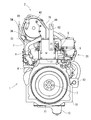
- the exhaust gas purification device 2 is located within the installation width L2 of the alternator 23 and the EGR device 26 as a generator and above the cooling water pump 21 in a front view. That is, the longitudinal length L1 of the exhaust gas purification device 2 is smaller than the installation width L2 corresponding to the full width of the engine 1.
- the exhaust gas purification device 2 is positioned above the cooling water pump 21 so as to be within the installation width L2 corresponding to the full width of the engine 1. For this reason, even if it is the engine 1 which assembled
- the piping 64 between the turbocharger 60 and the exhaust gas purification device 2 and the piping 66 between the turbocharger 60 and the EGR device 26 can be arranged without being restricted by the exhaust gas purification device 2.
- the degree of freedom of installation of the pipes 64 and 66 can be improved.
- An exhaust gas discharge pipe 64 is bolted to the exhaust manifold 7 and the turbine case 61 of the turbocharger 60.
- the purification inlet pipe 36 of the exhaust gas purification device 2 (purification casing 38) is bolted to the exhaust gas discharge pipe.
- Exhaust gas in the exhaust manifold 7 is supplied from the turbine case 61 of the turbocharger 60 to the exhaust gas purification device 2 via the exhaust gas discharge pipe 64.
- the exhaust gas discharge pipe 64 also functions as a casing support that supports the exhaust gas purification device 2.
- the engine 1 is provided with an inlet side bracket body 71 and an outlet side bracket body 72 for supporting and fixing the exhaust gas purifying device 2.
- the inlet side bracket body 71 is made of sheet metal
- the outlet side bracket body 72 is made of cast iron.
- the inlet side bracket body 71 corresponds to a sheet metal bracket body
- the outlet side bracket body 72 corresponds to a cast iron bracket body. That is, the combination of the inlet side bracket body 71 and the outlet side bracket body 72 corresponds to two types of bracket bodies.
- the materials of the bracket bodies 71 and 72 are different from those made of cast iron or sheet metal.
- the material itself of each bracket body 71, 72 is not limited to cast iron or sheet metal, but may be other materials such as die-cast.
- the lower end side of the inlet side bracket body 71 is bolted to the left side front portion of the cylinder head 5.
- the lower end side of the outlet side bracket body 72 is bolted to the front side of the cylinder head 5, and the upper and lower middle parts of the outlet side bracket body 72 are bolted to the upper surface of the intake manifold 6 via the connection bracket 73.
- the connection bracket 73 is made of the same sheet metal as the inlet side bracket body 71 and corresponds to a sheet metal auxiliary bracket.
- An inlet side bracket body 71 and an outlet side bracket body 72 are erected on the front side of the cylinder head 5.
- the mounting reference position of the exhaust gas purification device 2 with respect to the engine 1 can be set with high accuracy. For this reason, even if the exhaust gas purification device 2 is heavier than a muffler or the like as a post-processing device, it can be properly mounted at a predetermined position.
- the connection strength (rigidity) of the outlet side bracket body 72 to the engine 1 can be sufficiently secured by the connection of the intake manifold 6 and the outlet side bracket body 72 via the connection bracket 73, and exhaust due to vibration of the engine 1 or the like. It is possible to prevent deterioration and damage of the gas purification device 2 and contribute to improving the durability of the exhaust gas purification device 2.
- a reinforcing plate 74 is provided on the upper end side of the inlet side bracket body 71.
- the distal end portion (right end portion) of the reinforcing plate portion 74 of the inlet side bracket body 71 is connected to the upper end side of the outlet side bracket body 72. That is, a single mounting base 70 is configured by connecting the inlet side bracket body 71 and the outlet side bracket body 72 through the reinforcing plate portion 74.
- the receiving bracket 75 welded and fixed to the exhaust downstream side of the outer peripheral surface of the purification casing 38 is bolted to the base end portion (left end portion) of the reinforcing plate portion 74 fixed to the upper end side of the inlet side bracket body 71.
- the upper end side of the outlet side bracket body 72 is bolted to the intermediate clamping flange 45 of the purification casing 38.
- the exhaust-gas purification device 2 (purification casing 38) is supported on the cylinder head 5 of the engine 1 by the inlet-side bracket body 71 and the outlet-side bracket body 72 which are a single mounting base 70.
- the arrangement restriction of the exhaust gas purification device 2 can be reduced, and the arrangement of the exhaust gas purification device 2 on the upper side of the engine 1 can be reduced.
- the degree of freedom is improved.
- the exhaust gas purifying device 2 can be mounted on the upper side of the engine 1 while ensuring sufficient support strength in a small space by the single mounting base 70 including the outlet side bracket body 72 and the inlet side bracket body 71. It becomes possible.
- the engine 1 of the first embodiment includes a pair of lifting hardware 81 and 82.
- the pair of lifting brackets 81 and 82 are arranged separately on both side surfaces intersecting the output shaft 3 in the engine 1.
- the lifting brackets 81 and 82 of the first embodiment are distributed to the front side and the rear side of the cylinder head 5 in the engine 1.
- the second lifting bracket 82 is a long plate-shaped metal plate.
- a through suspension hole 86 for inserting a wire rope or the like is formed on the upper end side of the second lifting bracket 82, for example.
- the lower end side of the second lifting bracket 82 is bolted to the rear surface of the cylinder head 5.
- the first lifting bracket 81 is a metal plate bent into a crank shape.
- a through suspension hole 83 for inserting a wire rope or the like is formed on the upper end side of the first lifting bracket 82.
- the lower end side of the first lifting bracket 81 is bolted to the mounting base 70.
- a bolt hole 81 a is formed on the lower end side of the first lifting bracket 81.
- the upper side of the die cast outlet side bracket body 72 constituting the mounting base 70 protrudes upward from the upper surface of the cylinder head 5.
- a bolt hole 72a as a fastening portion is formed on the outer side (rear side) facing the cylinder head 5 of the engine 1 in the upper side of the outlet side bracket body 72.
- the lower end side of the first lifting bracket 81 is overlapped with the rear side surface of the upper side of the outlet side bracket body 72, and the fastening bolt 84 is connected to the bolt hole 81 a of the first lifting bracket 81 and the bolt hole 72 a of the outlet side bracket body 72. Is screwed outward from the head cover 8 toward the cooling fan 9, so that the first lifting bracket 81 is detachably fixed to the outlet side bracket body 72.
- the bolt hole 72a as the fastening portion is formed in the rear side surface on the upper side of the outlet side bracket body 72, the fastening bolt 84 for fastening the first lifting bracket 81 can be easily screwed in.
- the rear side surface of the upper side of the outlet side bracket body 72 is located below the exhaust gas purification device 2 so as to be hidden by the exhaust gas purification device 2 in plan view.
- the first lifting bracket 81 is formed in a crank shape, and the lower end of the first lifting bracket 81 is fastened to the rear side surface of the upper side of the outlet side bracket body 72 by bolts 84 to interfere with the exhaust gas purification device 2.
- the first lifting bracket 81 is bent so as to be along the outer peripheral side of the exhaust gas purification device 2, and the upper end side of the first lifting bracket 81 is extended upward. Therefore, the upper end side is closer to the center side of the engine 1 than the lower end side of the first lifting bracket 81, and the upper end side of the first lifting bracket 81 covers the cylinder head 5 side.
- the outlet side bracket body 72 which is a highly rigid component that supports the exhaust gas purification device 2, is also used as a fastening portion for the first lifting bracket 81, while the number of components is reduced,
- the 1 lifting bracket 81 can be firmly fastened (the connection strength of the first lifting bracket 81 to the engine 1 can be secured). Further, the first lifting bracket 81 can be assembled to the engine 1 in a space-saving manner while ensuring the balance of the entire engine 1 during lifting and avoiding the interference between the exhaust gas purification device 2 and the first lifting bracket 81.
- a reinforcing rib 85 is welded and fixed to the bent inner surface side of the lower bent portion of the first lifting bracket 81.
- the rigidity of the first lifting bracket 81 is improved by the rib effect due to the presence of the reinforcing rib 85.
- the strength of the first lifting bracket 81 is set smaller than the strength of the outlet side bracket body 72. For this reason, for example, when an excessive external force is applied when the engine 1 is lifted, the first lifting bracket 81 is plastically deformed or damaged before the outlet side bracket body 72. That is, the deformation of the outlet side bracket body 72 due to the lifting of the engine 1 can be prevented, and as a result, the application of external force to the exhaust gas purification device 2 when the engine 1 is lifted can be suppressed.
- a single mounting base 70 is configured by connecting the outlet side bracket body 72 and the inlet side bracket body 71, and the lower end side of the first lifting bracket 81 is fastened to the outlet side bracket body 72.
- the exhaust gas purification device 2 can be mounted on the engine 1 while sufficiently securing the support strength in a small space by the single mounting base 70 including the outlet side bracket body 72 and the inlet side bracket body 71.
- the strength of the outlet side bracket body 72 can be supplemented by the connection with the inlet side bracket body 71, and it is possible to more reliably prevent external force from being applied to the exhaust gas purification device 2 when the engine 1 is lifted.
- the exhaust gas purification device 2 of the second embodiment is disposed above the exhaust manifold 7 on the upper surface side of the engine 1.
- the attitude of the exhaust gas purification device 2 is set so that the longitudinal direction of the exhaust gas purification device 2 extends in parallel with the output shaft 3 of the engine 1.
- the purification inlet pipe 36 of the exhaust gas purification device 2 (purification casing 38) is connected to the outlet portion of the exhaust manifold 7.
- the outlet side bracket body 72 of the second embodiment is arranged side by side with the exhaust manifold 7 on the left side front portion of the cylinder head 5 (the cooling fan 9 side of the left side surface).
- the lower end side of the outlet side bracket 72 is bolted to the front portion of the left side surface of the cylinder head 5.
- the upper end side of the outlet side bracket body 72 is bolted to the outlet holding flange 54 of the purification casing 38.
- the inlet side bracket body 71 of the second embodiment is disposed on the rear side of the cylinder head 5 (above the mounting plate 10).
- the lower end side of the inlet side bracket body 71 is bolted to the rear surface of the cylinder head 5.
- An extension bracket 76 is bolted to the upper end side of the inlet side bracket body 71.
- the distal end side of the extension bracket is fastened to an inlet side lid body 43 that closes the exhaust upstream end of the purification casing 38 via bolts and nuts.
- the lifting brackets 81 and 82 of the second embodiment are arranged separately on the left side and the rear side of the cylinder head 5 in the engine 1.
- the second lifting bracket 82 is a crank-shaped metal plate.
- a through suspension hole 86 for inserting a wire rope or the like is formed on the upper end side of the second lifting bracket 82, for example.
- the lower end side of the second lifting bracket 82 is bolted to the outer surface of the inlet side bracket body 71.
- the first lifting bracket 81 is a metal plate bent into a square shape.
- a through suspension hole 83 for inserting a wire rope or the like is formed on the upper end side of the first lifting bracket 82.
- the lower end side of the first lifting bracket 81 is bolted to the outer side surface (upper left side surface) opposite to the cylinder head 5 in the upper side of the outlet side bracket body 72.
- a bolt hole 81 a is formed on the lower end side of the first lifting bracket 81.
- a bolt hole 72 a as a fastening portion is formed on the left side upper part of the outlet side bracket body 72.
- the lower end side of the first lifting bracket 81 is overlaid on the upper left side of the outlet side bracket body 72, and the fastening bolt 84 is inserted into the bolt hole 81 a of the first lifting bracket 81 and the bolt hole 72 a of the outlet side bracket body 72.
- the first lifting bracket 81 is detachably fixed to the outlet side bracket body 72 by screwing inward toward the head 5.
- the upper left side of the outlet side bracket body 72 is also located below the exhaust gas purification device 2 so as to be hidden by the exhaust gas purification device 2 in plan view.
- the first lifting bracket 81 is formed in a square shape, and the lower end portion of the first lifting bracket 81 is bolted to the upper part of the left side surface of the outlet side bracket body 72 to avoid interference with the exhaust gas purification device 2. Therefore, the first lifting bracket 81 is bent so as to be along the outer peripheral side of the exhaust gas purification device 2, and the upper end side of the first lifting bracket 81 is extended upward.
- the outlet-side bracket body 72 that is a highly rigid component that supports the exhaust gas purification device 2 is also used as a fastening portion for the first lifting bracket 81, and the first lifting bracket 81 is attached to the engine 1 while suppressing the number of components. Can be firmly fastened (the connection strength of the first lifting bracket 81 to the engine 1 can be secured). Further, the first lifting bracket 81 can be assembled to the engine 1 in a space-saving manner while ensuring the balance of the entire engine 1 during lifting and avoiding the interference between the exhaust gas purification device 2 and the first lifting bracket 81.
- the exhaust gas purification device 2 of the third embodiment is also disposed above the exhaust manifold 7 on the upper surface side of the engine 1.
- the attitude of the exhaust gas purification device 2 is set so that the longitudinal direction of the exhaust gas purification device 2 extends in parallel with the output shaft 3 of the engine 1.
- the exhaust gas intake side of the purification inlet pipe 36 of the purification casing 38 is fastened to the outlet portion of the exhaust manifold 7.
- the exhaust gas from the exhaust manifold 7 is supplied to the exhaust gas purification device 2 via the purification inlet pipe 36.
- the exhaust manifold 7 also functions as a casing support that supports the exhaust gas purification device 2. In this case, the exhaust manifold 7 supports a longitudinal midway portion of the purification casing 38 via the purification inlet pipe 36.
- the engine 1 is provided with an inlet side bracket body 71 and an outlet side bracket body 72 for supporting and fixing the exhaust gas purifying device 2.
- the inlet side bracket body 71 and the outlet side bracket body 72 are formed wide in a direction intersecting the output shaft 3 of the engine 1.
- the inlet side bracket body 71 and the outlet side bracket body 72 are detachably fixed to the cylinder head 5 of the engine 1.
- the inlet side bracket body 71 and the outlet side bracket body 72 are erected on the front side and the rear side that intersect the output shaft 3 in the cylinder head 5.
- the inlet side bracket body 71 is located on the rear surface side of the cylinder head 5 and supports the exhaust upstream side of the purification casing 38.
- the outlet side bracket body 72 is located on the front side of the cylinder head and supports the exhaust downstream side of the purification casing 38.
- the inlet side bracket body 71 and the outlet side bracket body 72 correspond to a mounting base.
- the inlet side bracket body 71 is disposed on the rear surface side of the cylinder head 5 (above the mounting plate 10) as described above.
- the lower end side of the inlet side bracket body 71 is bolted to the rear surface of the cylinder head 5.
- An extension bracket 76 is bolted to the upper end side of the inlet side bracket body 71.
- the distal end side of the extension bracket 76 is fastened to an inlet side lid 43 that closes the exhaust upstream end of the purification casing 38 via bolts and nuts.
- the exhaust upstream side of the purification casing 38 is detachably fixed to the rear surface side of the cylinder head 5 via the inlet side bracket body 71.
- the outlet side bracket body 72 is disposed on the front surface side (cooling fan 9 side) of the cylinder head 5 as described above.
- the outlet side bracket body 72 of the embodiment is configured to be separated into an intake side bracket 91 and an exhaust side bracket 92.
- the lower end side of the intake side bracket 91 is bolted to the front side of the cylinder head 5.
- a reinforcing bracket 93 is bolted to the upper surface of the intake manifold 6.
- the front side of the reinforcing bracket 93 is overlapped with the upper and lower halfway part on the rear surface side of the intake side bracket 91, and both 91 and 93 are bolted.
- a first lifting bracket 81 described later is attached to an upper and lower halfway portion on the front side of the intake side bracket 91. In this case, these three members 81, 91, 93 are fastened together with the reinforcing bracket 93 and the first lifting bracket 81 sandwiching the middle part of the intake side bracket 91.
- the exhaust side bracket 92 is formed by welding and fixing a rear frame plate 95 having a square cross section to the rear surface side of the front frame plate 94 having a substantially downward C opening.
- the base end side of the front frame plate 95 is bolted to the bracket fastening portion 54 a of the outlet holding flange 54 in the purification casing 38 via the spacer body 96. That is, one end side of the exhaust gas purification device 2 is connected to the exhaust side bracket 92.
- the intake side bracket 91 may be connected to one end side of the exhaust gas purification device 2.
- an embedded bolt 97 as a locking shaft body is provided on the front end side of the front frame plate 94 in the exhaust side bracket 92.
- the embedded bolt 97 projects forward from the front surface of the front frame plate 94.
- an upward opening temporary fixing notch 98 is formed on the upper end side of the intake side bracket 91. That is, a bolt hole for inserting the embedded bolt 97 formed on the upper end side of the intake side bracket 91 is cut out in an upwardly open shape to form a temporary fixing notch 98.
- An embedding bolt 97 of the front frame plate 94 can be locked to a temporary fixing notch 98 on the upper end side of the intake side bracket 91.
- the front end of the front frame plate 94 of the exhaust side bracket 92 is overlapped with the upper end of the rear surface of the intake side bracket 91, and the embedded bolt 97 is engaged with the temporary fixing notch 98.
- the bracket 92 and thus the purification casing 38 is supported.
- the exhaust downstream side of the purification casing 38 can be held at a predetermined position by the engagement of the embedded bolt 97 and the temporary fixing notch 98. That is, by engaging the embedded bolt 97 and the temporary fixing notch 98, the assembly position of the exhaust-side bracket 92 with respect to the intake-side bracket 91, and hence the mounting position of the exhaust gas purification device 2 with respect to the engine 1, can be easily determined.
- an embedded bolt 97 may be provided in the intake side bracket 91 and a temporary fixing notch 98 may be provided in the exhaust side bracket 92.
- the opening direction of the temporary fixing notch 98 may be set according to the positional relationship with the embedded bolt 97 and is not limited to the upward opening shape.
- the front end side of the front frame plate 94 in the exhaust side bracket 92 and the upper end side of the rear side of the intake side bracket 91 are bolted.
- a locking nut 99 is screwed into the embedding bolt 97 (tightening), and the one end sides of the intake side bracket 91 and the exhaust side bracket 92 are connected to each other.
- the lower end side of the rear frame plate 95 in the exhaust side bracket 92 is bolted to the left side front portion of the cylinder head 5.
- the exhaust downstream side of the purification casing 38 is detachably fixed to the front surface and the left front portion (front surface side) of the cylinder head 5 via the outlet side bracket body 72.
- the assembly position of the exhaust side bracket 92 with respect to the intake side bracket 91 and the mounting position of the exhaust gas purification device 2 with respect to the engine 1 can be easily determined by the engagement of the embedded bolt 97 and the temporary fixing notch 98. it can. Further, it is not necessary to perform assembly work such as bolt fastening or removal work while supporting the entire weight of the exhaust gas treatment device 2, and when the exhaust gas purification device 2 is loaded or unloaded, or assembling and disassembling the exhaust gas purification device 2. The labor at the time of work can be greatly reduced.
- the intake side bracket 91 and the exhaust side bracket 92 are used as the mounting base that supports one end side of the exhaust gas purification device 2 (exit side bracket body 72).
- the intake side bracket 91 and the exhaust side bracket 92 are fastened to each other, and the other end sides of the intake side bracket 91 and the exhaust side bracket 92 are connected to the engine 1 (cylinder head 5) side. Therefore, the mounting base (exit-side bracket body 72) is separated into the intake-side bracket 91 and the exhaust-side bracket 92, and the brackets 91 and 92 are designed to reduce the weight of each bracket.
- the exhaust gas purification device 2 can be stably mounted on the engine 1 with sufficient support strength secured by fastening. Therefore, it is possible to prevent deterioration and damage of the exhaust gas purification device 2 due to vibrations of the engine 1 and the like, thereby contributing to improvement in durability of the exhaust gas purification device 2.
- one end side of the exhaust gas purification device 2 is connected to one of the intake side bracket 91 and the exhaust side bracket 92, so that the intake side bracket 91 and the exhaust-side bracket 92 can be mounted on and removed from the engine 1 in a state where one of the exhaust-side brackets 92 is connected to one end of the exhaust-gas purification device 2, and the assembly workability of the exhaust-gas purification device 2 with respect to the engine 1 Improvements can be made.
- the other of the intake side bracket 91 and the exhaust side bracket 92 can be used as a mounting seat for a lifting bracket 81 for lifting the engine 1, for example.
- a temporary fixing notch 98 is formed in one of the intake side bracket 91 and the exhaust side bracket 92, and the locking shaft body 97 provided on the remaining other side. Is configured to be able to be locked to the temporary fixing notch 98, and by engaging the locking shaft body 97 and the temporary fixing notch 98, the other bracket 92 (to one bracket 91 (92) is connected. 91), that is, the mounting position of the exhaust gas purification device 2 with respect to the engine 1 can be easily determined.
- the reference position for mounting the exhaust gas purifying device 2 with respect to the engine 1 can be set with high accuracy. For this reason, even if the exhaust gas purification device 2 is heavier than a muffler or the like as a post-processing device, it can be properly mounted at a predetermined position.
- the engine 1 of the third embodiment includes a pair of lifting hardware 81 and 82.
- the pair of lifting brackets 81 and 82 are arranged separately on both side surfaces intersecting the output shaft 3 in the engine 1.
- the lifting brackets 81 and 82 of the third embodiment are distributed to the front side and the rear side of the cylinder head 5 in the engine 1.
- the second lifting bracket 82 is a long plate-shaped metal plate.
- a through suspension hole 86 for inserting a wire rope or the like is formed on the upper end side of the second lifting bracket 82, for example.
- the lower end side of the second lifting bracket 82 is bolted to the rear surface of the cylinder head 5.
- the first lifting bracket 81 is also a long plate metal plate. On the upper end side of the first lifting bracket 81, a through suspension hole 83 for inserting a wire rope or the like is formed.
- the lower end side of the second lifting bracket 82 is bolted to the rear surface of the cylinder head 5.
- the lower end side of the first lifting bracket 81 is bolted to the intake side bracket 91.
- the upper and lower middle portions of the intake side bracket 91 are clamped by the reinforcing bracket 93 bolted to the upper surface of the intake manifold 6 and the lower end side of the first lifting bracket 81, and these three members 81, 91 are held in the clamped state. , 93 are tightened together.
- the first lifting bracket 81 may be provided on the exhaust side bracket 92.
- the strength of the first lifting bracket 81 is set to be smaller than the strength of the intake side bracket 91 and the reinforcing bracket 93. For this reason, for example, when an excessive external force is applied when the engine 1 is lifted, the first lifting bracket 81 is plastically deformed or damaged before the intake side bracket 91 and the reinforcing bracket 93. That is, the deformation of the intake side bracket 91 and the reinforcing bracket 93 due to the lifting of the engine 1 can be prevented, and as a result, the application of external force to the exhaust gas purification device 2 when the engine 1 is lifted can be suppressed.
- the same effects as those of the first and second embodiments can be obtained. That is, since the lower end side of the lifting bracket 81 for lifting the engine 1 is fastened to one of the intake side bracket 91 and the exhaust side bracket 92, a highly rigid component that supports the exhaust gas purification device 2 One of the brackets 91 and 92 is also used as a fastening portion for the lifting bracket 81, and the lifting bracket 81 can be firmly fastened to the engine 1 while suppressing the number of parts (for the engine 1). The connection strength of the lifting bracket 81 can be ensured).
- the exhaust gas purification device 2 for purifying the exhaust gas from the engine 1 is provided, and the longitudinal direction of the exhaust gas purification device 2 is the output of the engine 1.
- the exhaust gas purifying device 2 can be supported with high rigidity by using the cylinder head 5 which is a highly rigid part of the engine 1, and the exhaust gas due to vibration or the like can be supported. Damage purifier 2 can be prevented.
- the exhaust gas purification device 2 can be communicated with the exhaust manifold 7 at a close distance, so that the exhaust gas purification device 2 can be easily maintained at an appropriate temperature, and high exhaust gas purification performance can be maintained. As a result, the exhaust gas purification device 2 can also be reduced in size.
- the exhaust gas purifying device 2 is disposed near the cooling fan 9 on the upper surface side of the engine 1, the upper surface side of the cylinder head 5, the intake manifold 6 and the exhaust manifold 7 is exposed over a wide range. This also facilitates maintenance work related to the engine 1.
- the exhaust gas purification device 2 is located between the head cover 8 on the cylinder head 5 and the cooling fan 9.
- the exhaust gas purification device 2 can be arranged by effectively utilizing the dead space existing between the head cover 8 and the cooling fan 9 on the upper surface side. Therefore, even the engine 1 assembled with the exhaust gas purification device 2 can have a structure in which the overall height is kept as low as possible, and the engine 1 can be made compact.
- an electrical wiring connector for the detection member 44 for the exhaust gas purification device 2 is provided on the opposite side of the outer periphery of the exhaust gas purification device 2 from the cooling fan 9. 44a is disposed, the electrical wiring connector 44a can be positioned at a height that is substantially the same as or lower than the upper end of the exhaust gas purification device 2, and the exhaust gas purification device 2 is The influence of the arrangement of the electrical wiring connector 44a can be reduced or eliminated with respect to the total height of the engine 1 including the engine 1. For this reason, in the engine 1 to which the exhaust gas purification device 2 is assembled, it is effective to keep the overall height as low as possible, and this point also contributes to the downsizing of the engine 1.
- the intake manifold 6 and the exhaust manifold 7 are distributed and arranged on both side surfaces along the output shaft 3 in the engine 1, and the engine 1
- a generator 23 is disposed on the exhaust manifold 7 side
- an EGR device 26 is disposed on the intake manifold 6 side of the engine 1
- a cooling water pump 21 is disposed on the cooling fan 9 side of the engine 1
- the generator 23 and the EGR device 26 and the exhaust gas purification device 2 is positioned above the cooling water pump 21, so the engine 1 with the exhaust gas purification device 2 assembled can be used. Even if it exists, it can be set as the structure which suppressed the full width as much as possible, and also contributes to the compactization of the said engine 1 also in this point.
- a pipe 64 between the turbocharger 60 and the exhaust gas purification device 2 and a pipe 66 between the turbocharger 60 and the EGR device 26 are restricted to the exhaust gas purification device 2. Therefore, the degree of freedom of installation of the pipes 64 and 66 can be improved. Further, the cooling air from the cooling fan 9 directly blows against the cooling water pump 21, and the presence of the exhaust gas purification device 2 does not hinder the cooling of the cooling water pump 21.
- the exhaust gas purifying device 2 for purifying the exhaust gas of the engine 1 is provided, and the exhaust gas is disposed on the upper side of the engine 1 via a mounting base 70.
- the engine device is equipped with the purification device 2, and a single mounting base 70 is configured by connecting two types of bracket bodies 71, 72, and the exhaust gas purification device 2 is connected to both the bracket bodies 71, 72. Therefore, as compared with the prior art in which the exhaust gas purification device is supported using an intake / exhaust manifold, the arrangement restriction of the exhaust gas purification device 2 can be reduced, and the upper side of the engine 1 can be The degree of freedom of arrangement of the exhaust gas purification device 2 is improved.
- the exhaust gas purifying device 2 can be mounted on the upper side of the engine 1 while ensuring sufficient support strength in a small space by the single mounting base 70 composed of the two types of bracket bodies 71 and 72. It becomes possible.
- the bracket bodies 71 and 72 are made of different materials, one of which is a cast iron bracket body 72 and the other of which is a sheet metal bracket body 71. Since the cast iron bracket body 72 is fastened to one cylinder head 5, the fastening reference position of the exhaust gas purification device 2 with respect to the engine 1 can be set with high accuracy by the fastening, and the muffler which is a post-processing device Even if the exhaust gas purification device 2 is heavier than the above, it can be properly mounted at a predetermined position.
- the bracket bodies 71 and 72 are made of different materials, one of which is a cast iron bracket body 72 and the other of which is a sheet metal bracket body 71.
- An upper end side of the bracket body 72 is fastened to the exhaust gas purification device 2
- a lower end side of the cast iron bracket body 72 is fastened to the cylinder head 5 of the engine 1
- a sheet metal auxiliary is attached to the intake manifold 6 of the engine 1. Since the upper and lower middle parts of the cast iron bracket body 72 are connected via the bracket 73, the engine is connected to the intake manifold 6 and the cast iron bracket body 72 via the sheet metal auxiliary bracket 73.
- connection strength rigidity
- gas purifier 2 which contributes to improved durability of the exhaust gas purifying device 2.
- the exhaust gas purifying device 2 for purifying the exhaust gas of the engine 1 is provided.
- the lifting bracket 81 can be firmly fastened to the engine 1 while suppressing the number of parts (the connection strength of the lifting bracket 81 to the engine 1 can be secured).
- the lifting bracket 81 can be assembled to the engine 1 in a space-saving manner while ensuring the balance of the entire engine 1 during lifting and avoiding interference between the exhaust gas purification device 2 and the lifting bracket 81. .
- the fastening portion for the lifting bracket 81 is formed on the outer surface of the mounting base 70 (72). 72), the fastener 84 for fastening the lifting bracket 81 can be easily screwed in.
- the strength of the lifting bracket 81 is set smaller than the strength of the mounting base 70 (72), deformation of the mounting base 70 (72) due to the lifting of the engine 1 can be prevented. It is possible to suppress external force from being applied to the exhaust gas purification device 2 when the engine 1 is lifted.
- a single mounting base 70 is configured by connecting a cast iron bracket body 72 and a sheet metal bracket body 71, and the cast iron bracket Since the lower end side of the lifting bracket 81 is fastened to the body 72, the single mounting base 70 comprising the cast iron bracket body 72 and the sheet metal bracket body 71 provides sufficient support strength in a small space.
- the exhaust gas purification device 2 can be mounted on the engine 1 while ensuring.
- the strength of the cast iron bracket body 72 can be supplemented by the connection with the sheet metal bracket body 71, and it is possible to more reliably prevent external force from being applied to the exhaust gas purification device 2 when the engine 1 is lifted.
Landscapes
- Engineering & Computer Science (AREA)
- Chemical & Material Sciences (AREA)
- Combustion & Propulsion (AREA)
- Mechanical Engineering (AREA)
- General Engineering & Computer Science (AREA)
- Transportation (AREA)
- Chemical Kinetics & Catalysis (AREA)
- Exhaust Gas After Treatment (AREA)
- Cooling, Air Intake And Gas Exhaust, And Fuel Tank Arrangements In Propulsion Units (AREA)
- Exhaust Gas Treatment By Means Of Catalyst (AREA)
- Processes For Solid Components From Exhaust (AREA)
Description
本願発明は、例えば建設土木機械、農作業機及びエンジン発電機といった作業機に搭載されるエンジン装置に関するものである。
昨今、ディーゼルエンジン(以下単にエンジンという)に関する高次の排ガス規制が適用されるのに伴い、エンジンが搭載される建設土木機械、農作業機及びエンジン発電機等に、排気ガス中の大気汚染物質を浄化処理する排気ガス浄化装置を搭載することが望まれている。排気ガス浄化装置としては、排気ガス中の粒子状物質等を捕集するディーゼルパティキュレートフィルタ(以下、DPFという)が知られている(特許文献1~3参照)。
DPFにおいては、経年使用でスートフィルタに堆積する粒子状物質を、エンジンの駆動時に燃焼除去させてスートフィルタを再生させる技術がある。よく知られるように、スートフィルタ再生動作は、排気ガス温度が再生可能温度(例えば300℃程度)以上で生ずるから、DPFを通過する排気ガス温度は再生可能温度以上であることが望ましい。このため、以前から、DPFを排気ガス温度が高い位置、すなわちエンジンに直接搭載したいという要請がある。
ところで、従来からエンジンには、これを作業機に載せ降ろしする際に用いる吊上げ金具を備えている。この種の吊上げ金具は、支持強度の関係上、エンジンのシリンダヘッドやシリンダブロックに締結する。エンジンを作業機に載せ降ろしする際は、例えば一対の吊上げ金具に形成された貫通穴にワイヤロープを挿通させ、ワイヤロープをチェンブロックのフック等に係止して、エンジンを吊り上げる。
エンジンにDPFを取り付ける場合、エンジンと吊上げ金具との連結強度の確保や、吊り上げ時におけるエンジン全体のバランスの確保等を鑑みて、例えばDPFと吊上げ金具との干渉を回避するというように、DPF及び吊上げ金具の位置関係を考慮する必要がある。
本願発明は、上記のような現状を検討して改善を施したエンジン装置を提供することを技術的課題としている。
請求項1の発明は、エンジンの排気ガスを浄化処理する排気ガス浄化装置を備えており、前記エンジンに取付け台を介して前記排気ガス浄化装置を搭載しているエンジン装置であって、前記エンジンを吊り上げるための吊上げ金具の下端側を前記取付け台に締結し、前記排気ガス浄化装置の外周側に沿わせるように、前記吊上げ金具の上端側を延出させているというものである。
請求項2の発明は、請求項1に記載のエンジン装置において、前記吊上げ金具に対する締結部を前記取付け台の外側面に形成しているというものである。
請求項3の発明は、請求項2に記載のエンジン装置において、前記取付け台の強度に比べて前記吊上げ金具の強度を小さく設定しているというものである。
請求項4の発明は、請求項3に記載のエンジン装置において、鋳鉄製ブラケット体と板金製ブラケット体との連結によって単一の前記取付け台を構成し、前記鋳鉄製ブラケット体に前記吊上げ金具の下端側を締結しているというものである。
請求項1の発明によると、エンジンの排気ガスを浄化処理する排気ガス浄化装置を備えており、前記エンジンに取付け台を介して前記排気ガス浄化装置を搭載しているエンジン装置であって、前記エンジンを吊り上げるための吊上げ金具の下端側を前記取付け台に締結し、前記排気ガス浄化装置の外周側に沿わせるように、前記吊上げ金具の上端側を延出させているから、前記排気ガス浄化装置を支持する高剛性部品である前記取付け台を前記吊上げ金具に対する締結部に兼用して、部品点数を抑制しながら、前記エンジンに前記吊上げ金具を強固に締結できる(前記エンジンに対する前記吊上げ金具の連結強度を確保できる)。
請求項2の発明によると、前記吊上げ金具に対する締結部を前記取付け台の外側面に形成しているから、前記取付け台に前記吊上げ金具を締結するための締結具を簡単にねじ込み操作でき、吊り上げ時における前記エンジン全体のバランスを確保し且つ前記排気ガス浄化装置と前記吊上げ金具との干渉を回避しながら、前記エンジンに対して前記吊上げ金具を省スペースに組み付けできる。
請求項3の発明によると、前記取付け台の強度に比べて前記吊上げ金具の強度を小さく設定しているから、前記エンジン吊上げによる前記取付け台の変形を防止でき、その結果、前記エンジン吊上げ時に前記排気ガス浄化装置に外力が加わるのを抑制できる。
請求項4の発明によると、鋳鉄製ブラケット体と板金製ブラケット体との連結によって単一の前記取付け台を構成し、前記鋳鉄製ブラケット体に前記吊上げ金具の下端側を締結しているから、前記鋳鉄製ブラケット体と前記板金製ブラケット体とからなる単一の前記取付け台によって、省スペースで支持強度を十分に確保しながら、前記エンジンに前記排気ガス浄化装置を搭載できる。前記板金製ブラケット体との連結によって前記鋳鉄製ブラケット体の強度を補完でき、前記エンジン吊上げ時に前記排気ガス浄化装置に外力が加わるのをより確実に防止できる。
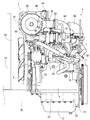
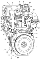
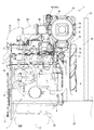
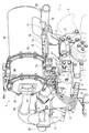
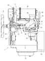
以下に、本発明を具体化した実施形態を図面に基づいて説明する。まず、図1~図8を参照しながら、第1実施形態におけるコモンレール式のエンジン1の概略構造について説明する。なお、以下の説明では、出力軸3に沿う両側部(出力軸3を挟んだ両側部)を左右、冷却ファン9配置側を前側、フライホイル11配置側を後側、排気マニホールド7配置側を左側、吸気マニホールド6配置側を右側と称し、これらを便宜的に、エンジン1における四方及び上下の位置関係の基準としている。
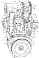
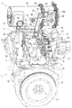
図1~図8に示すように、建設土木機械や農作業機といった作業機に搭載される原動機としてのエンジン1は、連続再生式の排気ガス浄化装置2(DPF)を備えている。排気ガス浄化装置2によって、エンジン1から排出される排気ガス中の粒子状物質(PM)が除去されると共に、排気ガス中の一酸化炭素(CO)や炭化水素(HC)が低減される。
エンジン1は、出力軸3(クランク軸)とピストン(図示省略)とを内蔵するシリンダブロック4を備える。シリンダブロック4上にシリンダヘッド5を搭載している。シリンダヘッド5の右側面に吸気マニホールド6を配置する。シリンダヘッド5の左側面に排気マニホールド7を配置する。すなわち、エンジン1において出力軸3に沿う両側面に、吸気マニホールド6と排気マニホールド7とを振り分けて配置する。シリンダヘッド5の上面にヘッドカバー8を配置する。エンジン1において出力軸3と交差する一側面、具体的にはシリンダブロック4の前面に、冷却ファン9を設ける。シリンダブロック4の後面にマウンティングプレート10を設ける。マウンティングプレート10に重なるようにフライホイル11を配置する。
出力軸3にフライホイル11を軸支する。作業機の作動部に出力軸3を介してエンジン1の動力を取り出すように構成している。また、シリンダブロック4の下面にはオイルパン12を配置する。オイルパン12内の潤滑油は、シリンダブロック4の右側面に配置されたオイルフィルタ13を介して、エンジン1の各潤滑部に供給される。
シリンダブロック4の右側面のうちオイルフィルタ13の上方(吸気マニホールド6の下方)には、燃料を供給するための燃料供給ポンプ14を取付ける。電磁開閉制御型の燃料噴射バルブ(図示省略)付きの3気筒分のインジェクタ15をエンジン1に設ける。各インジェクタ15に、燃料供給ポンプ14及び円筒状のコモンレール16及び燃料フィルタ(図示省略)を介して、作業機に搭載される燃料タンク(図示省略)を接続する。
前記燃料タンクの燃料が燃料フィルタ(図示省略)を介して燃料供給ポンプ14からコモンレール16に圧送され、高圧の燃料がコモンレール16に蓄えられる。各インジェクタ15の燃料噴射バルブをそれぞれ開閉制御することによって、コモンレール16内の高圧の燃料が各インジェクタ15からエンジン1の各気筒に噴射される。なお、マウンティングプレート10にエンジン始動用スタータ18を設けている。エンジン始動用スタータ18のピニオンギヤはフライホイル11のリングギヤに噛み合っている。エンジン1を始動させる際は、スタータ18の回転力にてフライホイル11のリングギヤを回転させることによって、出力軸3が回転開始する(いわゆるクランキングが実行される)。
シリンダヘッド5の前面側(冷却ファン9側)には、冷却水ポンプ21が冷却ファン9のファン軸と同軸状に配置されている。エンジン1の左側、具体的には冷却水ポンプ21の左側方に、エンジン1の動力にて発電する発電機としてのオルタネータ23が設けられている。出力軸3の回転にて、冷却ファン駆動用Vベルト22を介して、冷却ファン9と共に冷却水ポンプ21及びオルタネータ23が駆動する。作業機に搭載されるラジエータ19(図3及び図4参照)内の冷却水が、冷却水ポンプ21の駆動によって、シリンダブロック4及びシリンダヘッド5に供給され、エンジン1を冷却する。
オイルパン12の左右側面には、機関脚取付け部24がそれぞれ設けられている。各機関脚取付け部24には、防振ゴムを有する機関脚体(図示省略)をそれぞれボルト締結可能である。第1実施形態では、作業機における左右一対のエンジン支持シャーシ25にオイルパン12を挟持させ、当該オイルパン12側の機関脚取付け部24を各エンジン支持シャーシ25にボルト締結することによって、作業機の両エンジン支持シャーシ25がエンジン1を支持する。
なお、左右一対のエンジン支持シャーシ25には、ファンシュラウド20を背面側に取り付けたラジエータ19を、エンジン1の前面側に位置するように立設する。ファンシュラウド20は、冷却ファン9の外側(外周側)を囲っていて、ラジエータ19と冷却ファン9とを連通させている。冷却ファン9の回転によって、冷却風はラジエータ19に吹き当たり、その後、ラジエータ19からファンシュラウド20を経由してエンジン1に向けて流れる。
図4~図6等に示すように、吸気マニホールド6の入口部には、EGR装置26(排気ガス再循環装置)を介してエアクリーナ(図示省略)を連結する。EGR装置26は主としてエンジン1の右側、具体的にはシリンダヘッド5の右側方に配置されている。エアクリーナに吸い込まれた新気(外部空気)は、当該エアクリーナにて除塵及び浄化された後、ターボ過給機60のコンプレッサケース62(詳細は後述する)及びEGR装置26を介して吸気マニホールド6に送られ、エンジン1の各気筒に供給される。
EGR装置26は、エンジン1の排気ガスの一部(EGRガス)と新気とを混合させて吸気マニホールド6に供給するEGR本体ケース27と、コンプレッサケース62にEGR本体ケース27を連通させる吸気スロットル部材28と、排気マニホールド7にEGRクーラ29を介して接続される再循環排気ガス管30と、再循環排気ガス管30にEGR本体ケース27を連通させるEGRバルブ部材31とを備えている。
すなわち、吸気マニホールド6には、EGR本体ケース27を介して吸気スロットル部材28が連結されている。EGR本体ケース27には、再循環排気ガス管30の出口側を接続する。再循環排気ガス管30の入口側は、EGRクーラ29を介して排気マニホールド7に接続する。EGRバルブ部材31内のEGR弁の開度を調節することによって、EGR本体ケース27へのEGRガスの供給量が調節される。なお、EGR本体ケース27は、吸気マニホールド6に着脱可能にボルト締結される。
上記の構成において、エアクリーナからコンプレッサケース62及び吸気スロットル部材28を介してEGR本体ケース27内に新気を供給する一方、排気マニホールド7からEGR本体ケース27内にEGRガスを供給する。エアクリーナからの新気と排気マニホールド7からのEGRガスとがEGR本体ケース27内で混合された後、当該混合ガスが吸気マニホールド6に供給される。エンジン1から排気マニホールド7に排出された排気ガスの一部を吸気マニホールド6からエンジン1に還流することによって、高負荷運転時の最高燃焼温度が低下し、エンジン1からのNOx(窒素酸化物)の排出量が低減する。
シリンダヘッド5の左側方で排気マニホールド7の上方には、ターボ過給機60を配置する。ターボ過給機60は、タービンホイル内蔵のタービンケース61と、ブロアホイル内蔵のコンプレッサケース62とを備えている。排気マニホールド7の出口部にタービンケース61の排気ガス取込管63を連結する。タービンケース61の排気ガス排出管64には、排気ガス浄化装置2が接続される。すなわち、エンジン1の各気筒から排気マニホールド7に排出された排気ガスは、ターボ過給機60及び排気ガス浄化装置2等を経由して外部に放出される。
コンプレッサケース62の給気取込側は、給気管65を介してエアクリーナの給気排出側に接続される。コンプレッサケース62の給気排出側は、過給管66及びEGR装置26を介して吸気マニホールド6に接続される。すなわち、エアクリーナにて除塵された新気は、コンプレッサケース62から過給管66を介してEGR装置26に送られ、その後、エンジン1の各気筒に供給される。
次に、排気ガス浄化装置2について説明する。排気ガス浄化装置2は、浄化入口管36を有する浄化ケーシング38を備える。浄化ケーシング38の内部に、二酸化窒素(NO2)を生成する白金等のディーゼル酸化触媒39と、捕集した粒子状物質(PM)を比較的低温で連続的に酸化除去するハニカム構造のスートフィルタ40とを、排気ガス移動方向に直列に並べている。ディーゼル酸化触媒39及びスートフィルタ40は、浄化ケーシング38に収容されるガス浄化フィルタと言える。なお、浄化ケーシング38の排気ガス出口41に排気管を介して例えば消音器やテールパイプを連結し、排気ガス出口41から消音器やテールパイプを介して排気ガスを外部に排出する。
上記の構成において、ディーゼル酸化触媒39の酸化作用によって生成された二酸化窒素(NO2)がスートフィルタ40内に取り込まれる。エンジン1の排気ガス中に含まれる粒子状物質はスートフィルタ40に捕集され、二酸化窒素(NO2)によって連続的に酸化除去される。エンジン1の排気ガス中の粒状物質(PM)の除去に加え、エンジン1の排気ガス中の一酸化炭素(CO)や炭化水素(HC)の含有量が低減される。
浄化ケーシング38の排気上流側の外周部に浄化入口管36を設ける。浄化ケーシング38の排気下流側の端部には蓋体42を溶接固定する。浄化ケーシング38の排気下流側の端部を蓋体42によって塞いでいる。蓋体42の略中央部に排気ガス出口41を開口させている。
浄化ケーシング38に排気圧力センサ44を取り付けている。排気圧力センサ44はスートフィルタ40の上流側と下流側との間の排気ガスの圧力差を検出するものであり、排気ガスの圧力差を電気信号に変換して、エンジンコントローラ(図示省略)に出力するように構成している。スートフィルタ40の上下流間の排気圧力差に基づき、スートフィルタ40における粒子状物質の堆積量を演算し、スートフィルタ40内の詰り状態が把握される。
図1~図8に示すように、浄化ケーシング38の中間挟持フランジ45に、貫通穴付きのセンサ締結部46を、浄化ケーシング38の外周部のうち冷却ファン9と反対側(ヘッドカバー8側)に位置するように設ける。そして、電気配線コネクタ44aを一体的に設けた排気圧力センサ44を、中間挟持フランジ45のセンサ締結部46にボルト締結している。すなわち、排気ガス浄化装置2の外周部のうち冷却ファン9と反対側に、排気ガス浄化装置2に対する排気圧力センサ44用の電気配線コネクタ44aを配置している。排気圧力センサ44が検出部材に相当する。
排気圧力センサ44には、上流側センサパイプ47及び下流側センサパイプ48の一端側がそれぞれ接続される。浄化ケーシング38内のスートフィルタ40を挟むように、上流側及び下流側の各センサ配管ボス体49,50を浄化ケーシング38に設ける。管継手ボルト53を介して、各センサパイプ47,48の他端側に設けられた締結ボス体51,52を各センサ配管ボス体49,50に締結する。
上記の構成において、スートフィルタ40の上流(流入)側の排気ガス圧力と、スートフィルタ40の下流(流出)側の排気ガス圧力の差(排気ガスの差圧)が、排気圧力センサ44によって検出される。スートフィルタ40に捕集された排気ガス中の粒子状物質の残留量が排気ガスの差圧に比例するから、スートフィルタ40に残留する粒子状物質量が所定以上に増加したときに、排気圧力センサ44の検出結果に基づき、スートフィルタ40の粒子状物質量を減少させる再生制御(例えば排気温度を上昇させる制御)が実行される。また、再生制御可能範囲以上に、粒子状物質の残留量がさらに増加したときには、浄化ケーシング38を着脱分解して、スートフィルタ40を掃除し、粒子状物質を人為的に除去するメンテナンス作業が行われる。
上記のように、排気ガス浄化装置2の外周部のうち冷却ファン9と反対側に、排気ガス浄化装置2に対する排気圧力センサ44用の電気配線コネクタ44aを配置すると、排気ガス浄化装置2の上端とほぼ変わらないかそれよりも低い高さに、電気配線コネクタ44aを位置させることが可能になり、排気ガス浄化装置2を含むエンジン1全高に対して、電気配線コネクタ44aひいては排気圧力センサ44の配置の影響を少なくできるか又はなくせる。このため、排気ガス浄化装置2を組み付けたエンジン1において、全高を極力低く抑えるのに効果的であり、エンジン1のコンパクト化に貢献する。
また、排気圧力センサ44自体も、排気ガス浄化装置2の外周部のうち冷却ファン9と反対側に位置するから、冷却ファン9からの冷却風が排気圧力センサ44や各センサパイプ47,48に当たりにくい。このため、排気圧力センサ44や各センサパイプ47,48内の排気ガスが冷却ファン9からの冷却風によって冷やされるのを極力回避して、排気圧力センサ44の誤検出を防止でき、スートフィルタ40の粒子状物質量を減少させる再生制御の精度を向上できる(適正に実行できる)。
図5~図8に示すように、排気ガス浄化装置2はエンジン1の上面側のうち冷却ファン9寄りの箇所でシリンダヘッド5に支持させている。このため、エンジン1に排気ガス浄化装置2を組み込んでから出荷可能なものでありながら、エンジン1の高剛性部品であるシリンダヘッド5を用いて、排気ガス浄化装置2を高剛性に支持でき、振動等による排気ガス浄化装置2の損傷を防止できる。また、排気マニホールド7に排気ガス浄化装置2を至近距離で連通できることになり、排気ガス浄化装置2を適正温度に維持し易く、高い排気ガス浄化性能の維持が可能になる。その結果、排気ガス浄化装置2の小型化にも貢献する。しかも、エンジン1の上面側のうち冷却ファン9寄りの箇所に排気ガス浄化装置2を配置するから、シリンダヘッド5、吸気マニホールド6及び排気マニホールド7の上面側を広範囲に露出でき、エンジン1関連のメンテナンス作業もし易くなる。
第1実施形態では、エンジン1の上面側のうちヘッドカバー8と冷却ファン9との間の空間がデッドスペースとして存在する。そこで、排気ガス浄化装置2の長手方向がエンジン1の出力軸3と直交するように、排気ガス浄化装置2をエンジン1の上面側のうちヘッドカバー8と冷却ファン9との間に位置させている。このため、排気ガス浄化装置2を組み付けたエンジン1であっても、全高を極力低く抑えた構造にでき、ヘッドカバー8と冷却ファン9との間のデッドスペースを有効利用して、エンジン1のコンパクト化を図れる。
第1実施形態では、冷却ファン9の外周側をファンシュラウド20にて囲っているので、冷却ファン9からの冷却風が排気ガス浄化装置2に直接吹き当たるのを抑制できる。このため、排気ガス浄化装置2中の排気ガス温度が冷却ファン9からの冷却風によって低下するのを極力回避して、排気ガス浄化装置2の排気ガス浄化性能を適正に維持できる。ただし、位置関係上、冷却水ポンプ21は冷却ファン9に対峙していて、冷却ファン9からの冷却風は冷却水ポンプ21に直接吹き当たる。従って、排気ガス浄化装置2の存在が冷却水ポンプ21の空冷を妨げることはない。
図1に示すように、排気ガス浄化装置2は、正面視において、発電機であるオルタネータ23とEGR装置26との設置幅L2内で、且つ、冷却水ポンプ21の上方に位置している。すなわち、エンジン1全幅に相当する前記設置幅L2よりも排気ガス浄化装置2の長手方向の長さL1の方が小さい。そして、エンジン1全幅に相当する前記設置幅L2内に収まる状態で、排気ガス浄化装置2を冷却水ポンプ21の上方に位置させている。このため、排気ガス浄化装置2を組み付けたエンジン1であっても、全幅を極力低く抑えた構造にでき、この点でもエンジン1のコンパクト化に寄与する。
また、ターボ過給機60と排気ガス浄化装置2との間の配管64、ターボ過給機60とEGR装置26との間の配管66を、排気ガス浄化装置2に規制されることなく配置でき、配管64,66設置の自由度を向上できる。
次に、エンジン1に排気ガス浄化装置2を組み付ける構造について説明する。排気マニホールド7とターボ過給機60のタービンケース61とに、排気ガス排出管64をボルト締結している。排気ガス浄化装置2(浄化ケーシング38)の浄化入口管36を排気ガス排出管にボルト締結している。排気ガス排出管64を介して、排気マニホールド7の排気ガスがターボ過給機60のタービンケース61から排気ガス浄化装置2に供給される。排気ガス排出管64は、排気ガス浄化装置2を支持するケーシング支持体としても機能している。
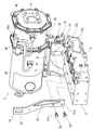
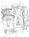
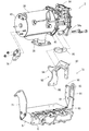
図9~図11に詳細に示すように、エンジン1には、排気ガス浄化装置2を支持固定するための入口側ブラケット体71及び出口側ブラケット体72を備えている。第1実施形態では、入口側ブラケット体71が板金製であり、出口側ブラケット体72が鋳鉄製である。入口側ブラケット体71が板金製ブラケット体に相当し、出口側ブラケット体72が鋳鉄製ブラケット体に相当する。つまり、入口側ブラケット体71と出口側ブラケット体72との組合せが2種類のブラケット体に相当する。前述の通り、第1実施形態では各ブラケット体71,72の素材を鋳鉄製又は板金製と異ならせている。各ブラケット体71,72の素材自体は、鋳鉄製又は板金製に限らず、ダイカスト製といった他の素材でも差し支えない。
シリンダヘッド5の左側面前部に入口側ブラケット体71の下端側をボルト締結している。シリンダヘッド5の前面側には出口側ブラケット体72の下端側をボルト締結すると共に、吸気マニホールド6の上面に連結ブラケット73を介して出口側ブラケット体72の上下中途部をボルト締結する。連結ブラケット73は、入口側ブラケット体71と同じ板金製であり、板金製補助ブラケットに相当する。シリンダヘッド5の前側に入口側ブラケット体71と出口側ブラケット体72とを立設させている。
上記のように、シリンダヘッド5の前面側に出口側ブラケット体72の下端側を締結することによって、エンジン1に対する排気ガス浄化装置2の取付け基準位置を高精度に設定できる。このため、後処理装置であるマフラー等に比べて重量の重い排気ガス浄化装置2であっても、所定の位置に適正に搭載できる。また、連結ブラケット73を介しての吸気マニホールド6と出口側ブラケット体72との連結によって、エンジン1に対する出口側ブラケット体72の連結強度(剛性)を充分に確保でき、エンジン1の振動等による排気ガス浄化装置2の劣化・損傷を防止して、排気ガス浄化装置2の耐久性向上に寄与できる。
入口側ブラケット体71の上端側には補強プレート部74を設ける。入口側ブラケット体71の補強プレート部74の先端部(右端部)を出口側ブラケット体72の上端側に連結する。すなわち、補強プレート部74を介して入口側ブラケット体71と出口側ブラケット体72とを連結することによって、単一の取付け台70を構成している。
入口側ブラケット体71の上端側に固定された補強プレート部74の基端部(左端部)に、浄化ケーシング38の外周面のうち排気下流側に溶接固定された受けブラケット75をボルト締結する。出口側ブラケット体72の上端側は浄化ケーシング38の中間挟持フランジ45にボルト締結する。単一の取付け台70である入口側ブラケット体71と出口側ブラケット体72とによって、エンジン1のシリンダヘッド5に排気ガス浄化装置2(浄化ケーシング38)を支持させている。このため、吸排気マニホールドを利用して排気ガス浄化装置を支持する前記従来技術に比べて、排気ガス浄化装置2の配置規制を少なくでき、エンジン1の上部側での排気ガス浄化装置2の配置自由度が向上する。出口側ブラケット体72と入口側ブラケット体71とからなる単一の取付け台70によって、省スペースで支持強度を十分に確保しながら、エンジン1の上部側に排気ガス浄化装置2を搭載することが可能になる。
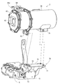
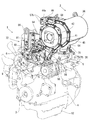
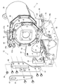
次に、図12~図15を参照しながら、エンジン1を作業機に載せ降ろしする際に用いる吊上げ金具81,82及びその取付け構造について説明する。第1実施形態のエンジン1は一対の吊上げ金具81,82を備えている。重量物である排気ガス浄化装置2付きエンジン1を安定した姿勢で(バランスさせて)吊り上げるため、一対の吊上げ金具81,82はエンジン1において出力軸3と交差する両側面側に振り分けて配置される。第1実施形態の吊上げ金具81,82は、エンジン1におけるシリンダヘッド5の前面側と後面側とに振り分けている。一対の吊上げ金具81,82のうち第2吊上げ金具82は長板状の金属板材である。第2吊上げ金具82の上端側には、例えばワイヤロープ等を挿通させるための貫通吊り穴86を形成している。第2吊上げ金具82の下端側はシリンダヘッド5の後面にボルト締結している。
第1吊上げ金具81はクランク形状に屈曲形成された金属板材である。第1吊上げ金具82の上端側には、例えばワイヤロープ等を挿通させるための貫通吊り穴83を形成している。第1吊上げ金具81の下端側は、取付け台70にボルト締結している。実施形態では、第1吊上げ金具81の下端側にボルト穴81aを形成している。一方、取付け台70を構成するダイカスト製の出口側ブラケット体72の上下中途部から上側は、シリンダヘッド5の上面よりも上方に突き出ている。出口側ブラケット体72の上部側のうちエンジン1のシリンダヘッド5向きの外側面(後側面)に、締結部としてのボルト穴72aを形成している。
出口側ブラケット体72の上部側の後側面に第1吊上げ金具81の下端側を重ね合わせて、第1吊上げ金具81のボルト穴81aと出口側ブラケット体72のボルト穴72aとに、締結ボルト84をヘッドカバー8から冷却ファン9に向かう外向きにねじ込むことによって、第1吊上げ金具81を出口側ブラケット体72に着脱可能に固定している。このように、出口側ブラケット体72の上部側の後側面に締結部としてのボルト穴72aを形成しているから、第1吊上げ金具81締結用の締結ボルト84を簡単にねじ込み操作できる。
出口側ブラケット体72の上部側の後側面は、平面視で排気ガス浄化装置2に隠れるように、排気ガス浄化装置2の下側に位置している。このため、第1吊上げ金具81をクランク形状に形成して、第1吊上げ金具81の下端部を出口側ブラケット体72の上部側の後側面にボルト84締結し、排気ガス浄化装置2との干渉回避のために排気ガス浄化装置2の外周側に沿わせるように第1吊上げ金具81を屈曲させ、第1吊上げ金具81の上端側を上向きに延出させている。従って、第1吊上げ金具81の下端側よりも上端側の方がエンジン1の中央側に近く、第1吊上げ金具81の上端側は、シリンダヘッド5側に被さっている。
このように構成すると、排気ガス浄化装置2を支持する高剛性部品である出口側ブラケット体72を、第1吊上げ金具81に対する締結部に兼用して、部品点数を抑制しながら、エンジン1に第1吊上げ金具81を強固に締結できる(エンジン1に対する第1吊上げ金具81の連結強度を確保できる)。また、吊り上げ時におけるエンジン1全体のバランスを確保し且つ排気ガス浄化装置2と第1吊上げ金具81との干渉を回避しながら、エンジン1に対して第1吊上げ金具81を省スペースに組み付けできる。
なお、第1吊上げ金具81のうち下屈曲部の屈曲内面側には、補強リブ85が溶接固定されている。補強リブ85の存在によるリブ効果で第1吊上げ金具81の剛性向上を図っている。ただし、第1吊上げ金具81の強度は、出口側ブラケット体72の強度に比べて小さく設定されている。このため、例えばエンジン1吊り上げの際に過大な外力がかかると、出口側ブラケット体72よりも先に第1吊上げ金具81の方が塑性変形したり破損したりする。すなわち、エンジン1吊上げによる出口側ブラケット体72の変形を防止でき、その結果、エンジン1吊上げ時に排気ガス浄化装置2に外力が加わるのを抑制できる。
実施形態では、出口側ブラケット体72と入口側ブラケット体71との連結によって単一の取付け台70を構成し、出口側ブラケット体72に第1吊上げ金具81の下端側を締結している。このため、出口側ブラケット体72と入口側ブラケット体71とからなる単一の取付け台70によって、省スペースで支持強度を十分に確保しながら、エンジン1に排気ガス浄化装置2を搭載できる。更に、入口側ブラケット体71との連結によって出口側ブラケット体72の強度を補完でき、エンジン1吊上げ時に排気ガス浄化装置2に外力が加わるのをより確実に防止できる。
上記の構成において、エンジン1を作業機に載せ降ろしする際は、両吊上げ金具81,82に形成された貫通吊り穴83,86に例えばワイヤロープを挿通させ、ワイヤロープをチェンブロックのフック等に係止して、エンジン1を吊り上げることになる。
次に、図16~図21を参照しながら、第2実施形態のエンジン1に対する排気ガス浄化装置2の搭載構造について説明する。なお、第2実施形態以降の実施形態において、構成及び作用が第1実施形態と同じものには同じ符号を付して、その詳細な説明を省略する。
第2実施形態の排気ガス浄化装置2は、エンジン1の上面側のうち排気マニホールド7の上方に配置されている。この場合、排気ガス浄化装置2の長手方向をエンジン1の出力軸3と平行に延びるように、排気ガス浄化装置2の姿勢を設定している。排気ガス浄化装置2(浄化ケーシング38)の浄化入口管36は、排気マニホールド7の出口部に連結する。
第2実施形態の出口側ブラケット体72は、シリンダヘッド5の左側面前部(左側面のうち冷却ファン9側)に、排気マニホールド7と並べて配置されている。出口側ブラケット72の下端側はシリンダヘッド5の左側面前部にボルト締結する。出口側ブラケット体72の上端側は浄化ケーシング38の出口挟持フランジ54にボルト締結する。
第2実施形態の入口側ブラケット体71は、シリンダヘッド5の後面側(マウンティングプレート10の上方)に配置されている。入口側ブラケット体71の下端側はシリンダヘッド5の後面にボルト締結する。入口側ブラケット体71の上端側には、延長ブラケット76をボルト締結する。延長ブラケットの先端側は、ボルト及びナットを介して、浄化ケーシング38の排気上流側の端部を塞ぐ入口側蓋体43に締結する。
第2実施形態の吊上げ金具81,82は、エンジン1におけるシリンダヘッド5の左側面側と後面側とに振り分けて配置されている。一対の吊上げ金具81,82のうち第2吊上げ金具82はクランク形状の金属板材である。第2吊上げ金具82の上端側には、例えばワイヤロープ等を挿通させるための貫通吊り穴86を形成している。第2吊上げ金具82の下端側は入口側ブラケット体71の外側面にボルト締結している。
第1吊上げ金具81はく字状に屈曲形成された金属板材である。第1吊上げ金具82の上端側には例えばワイヤロープ等を挿通させるための貫通吊り穴83を形成している。第1吊上げ金具81の下端側は、出口側ブラケット体72の上部側のうちシリンダヘッド5と反対側の外側面(左側面上部)にボルト締結している。第2実施形態では、第1吊上げ金具81の下端側にボルト穴81aを形成している。出口側ブラケット体72の左側面上部に、締結部としてのボルト穴72aを形成している。出口側ブラケット体72の左側面上部に第1吊上げ金具81の下端側を重ね合わせて、第1吊上げ金具81のボルト穴81aと出口側ブラケット体72のボルト穴72aとに、締結ボルト84をシリンダヘッド5に向かう内向きにねじ込むことによって、第1吊上げ金具81を出口側ブラケット体72に着脱可能に固定している。
出口側ブラケット体72の左側面上部も、平面視で排気ガス浄化装置2に隠れるように、排気ガス浄化装置2の下側に位置している。このため、第1吊上げ金具81をく字状に形成して、第1吊上げ金具81の下端部を出口側ブラケット体72の左側面上部にボルト締結し、排気ガス浄化装置2との干渉回避のために排気ガス浄化装置2の外周側に沿わせるように第1吊上げ金具81を屈曲させ、第1吊上げ金具81の上端側を上向きに延出させている。
第2実施形態の構成を採用した場合も、第1実施形態と同様の作用効果が得られる。すなわち、排気ガス浄化装置2を支持する高剛性部品である出口側ブラケット体72を、第1吊上げ金具81に対する締結部に兼用して、部品点数を抑制しながら、エンジン1に第1吊上げ金具81を強固に締結できる(エンジン1に対する第1吊上げ金具81の連結強度を確保できる)。また、吊り上げ時におけるエンジン1全体のバランスを確保し且つ排気ガス浄化装置2と第1吊上げ金具81との干渉を回避しながら、エンジン1に対して第1吊上げ金具81を省スペースに組み付けできる。
次に、図22~図32を参照しながら、第3実施形態のエンジン1に対する排気ガス浄化装置2の搭載構造について説明する。第3実施形態の排気ガス浄化装置2も、エンジン1の上面側のうち排気マニホールド7の上方に配置されている。この場合、排気ガス浄化装置2の長手方向をエンジン1の出力軸3と平行に延びるように、排気ガス浄化装置2の姿勢を設定している。排気マニホールド7の出口部に、浄化ケーシング38の浄化入口管36の排気ガス取込み側を締結している。排気マニホールド7の排気ガスが浄化入口管36を介して排気ガス浄化装置2に供給される。排気マニホールド7は、排気ガス浄化装置2を支持するケーシング支持体としても機能している。この場合、排気マニホールド7は、浄化入口管36を介して浄化ケーシング38の長手中途部を支持する。
図24~図26に詳細に示すように、エンジン1には、排気ガス浄化装置2を支持固定するための入口側ブラケット体71及び出口側ブラケット体72を備えている。入口側ブラケット体71及び出口側ブラケット体72は、エンジン1の出力軸3と交差する方向に幅広に形成されている。入口側ブラケット体71及び出口側ブラケット体72は、エンジン1のシリンダヘッド5に着脱可能に固定される。入口側ブラケット体71及び出口側ブラケット体72は、シリンダヘッド5において出力軸3と交差する前面側及び後面側に振り分けて立設している。入口側ブラケット体71は、シリンダヘッド5の後面側に位置して、浄化ケーシング38の排気上流側を支持する。出口側ブラケット体72は、シリンダヘッドの前面側に位置して、浄化ケーシング38の排気下流側を支持する。入口側ブラケット体71及び出口側ブラケット体72は取付け台に相当するものである。
図25、図28及び図30~図32に示すように、入口側ブラケット体71は前述の通り、シリンダヘッド5の後面側(マウンティングプレート10の上方)に配置される。入口側ブラケット体71の下端側をシリンダヘッド5の後面にボルト締結する。入口側ブラケット体71の上端側には、延長ブラケット76をボルト締結する。延長ブラケット76の先端側は、ボルト及びナットを介して、浄化ケーシング38の排気上流側の端部を塞ぐ入口側蓋体43に締結する。その結果、浄化ケーシング38の排気上流側は、入口側ブラケット体71を介してシリンダヘッド5の後面側に着脱可能に固定される。
図26~図32に示すように、出口側ブラケット体72は前述の通り、シリンダヘッド5の前面側(冷却ファン9側)に配置される。実施形態の出口側ブラケット体72は、吸気側ブラケット91と排気側ブラケット92とに分離構成されている。
吸気側ブラケット91の下端側をシリンダヘッド5の前面側にボルト締結する。吸気マニホールド6の上面には補強ブラケット93をボルト締結する。吸気側ブラケット91の後面側の上下中途部に補強ブラケット93の前面側を重ね合わせて、両者91,93をボルト締結する。なお、吸気側ブラケット91の前面側の上下中途部には、後述する第1吊上げ金具81を取り付ける。この場合、補強ブラケット93と第1吊上げ金具81とにより吸気側ブラケット91の上下中途部を挟持した状態で、これら三者81,91,93を共締めしている。
排気側ブラケット92は、下向き開口略C字状の前枠板94の後面側に断面く字状の後枠板95を溶接固定したものである。実施形態では、浄化ケーシング38における出口挟持フランジ54のブラケット締結部54aに、スペーサ体96を介して前枠板95の基端側をボルト締結している。すなわち、排気側ブラケット92に排気ガス浄化装置2の一端側を連結している。なお、エンジン1に対する排気ガス浄化装置2の搭載位置によっては、吸気側ブラケット91に排気ガス浄化装置2の一端側に連結してもよい。
図26、図27、図29及び図31に示すように、排気側ブラケット92における前枠板94の先端側には、係止軸体としての埋込みボルト97を設けている。埋込みボルト97は前枠板94の前面から前向きに突出させる。一方、吸気側ブラケット91の上端側には、上向き開口状の仮止めノッチ98を形成する。すなわち、吸気側ブラケット91の上端側に形成される埋込みボルト97挿入用のボルト穴を上向き開放状に切り欠いて、仮止めノッチ98を形成する。吸気側ブラケット91上端側の仮止めノッチ98に、前枠板94の埋込みボルト97を係止可能に構成している。排気側ブラケット92における前枠板94の前面先端側を吸気側ブラケット91の後面上端側に重ね合わせて、埋込みボルト97を仮止めノッチ98に係合させることによって、吸気側ブラケット91に、排気側ブラケット92ひいては浄化ケーシング38を支持させる。
埋込みボルト97と仮止めノッチ98との係合によって、浄化ケーシング38の排気下流側を所定位置に保持できる。つまり、埋込みボルト97と仮止めノッチ98との係合によって、吸気側ブラケット91に対する排気側ブラケット92の組付け位置、ひいてはエンジン1に対する排気ガス浄化装置2の搭載位置を簡単に位置決めできる。なお、実施形態とは逆に、吸気側ブラケット91に埋込みボルト97を設け、排気側ブラケット92に仮止めノッチ98を設けてもよい。仮止めノッチ98の開口方向は、埋込みボルト97との位置関係で設定すればよく、上向き開口状に限るものではない。
図31に示すように、埋込みボルト97を仮止めノッチ98に係合させた状態で、排気側ブラケット92における前枠板94の前面先端側と、吸気側ブラケット91の後面上端側とをボルト締結する。次いで、埋込みボルト97に係止ナット99をねじ込んで(増し締めして)、吸気側ブラケット91及び排気側ブラケット92の一端側同士を互いに連結する。排気側ブラケット92における後枠板95の下端側をシリンダヘッド5の左側面前部にボルト締結する。その結果、浄化ケーシング38の排気下流側は、出口側ブラケット体72を介してシリンダヘッド5の前面及び左側面前部(前面側)に着脱可能に固定される。
このように構成すると、埋込みボルト97と仮止めノッチ98との係合によって、吸気側ブラケット91に対する排気側ブラケット92の組付け位置、ひいてはエンジン1に対する排気ガス浄化装置2の搭載位置を簡単に位置決めできる。また、排気ガス処理装置2の全重量を支えながら、ボルト締結等の組付け作業や取外し作業をする必要がなくなり、排気ガス浄化装置2の載せ降ろし作業時や、排気ガス浄化装置2の組立分解作業時の手間を大幅に軽減できる。
上記の記載並びに図26~図31から明らかなように、取付け台のうち排気ガス浄化装置2の一端側を支持するもの(出口側ブラケット体72)として、吸気側ブラケット91及び排気側ブラケット92を備え、前記吸気側ブラケット91及び前記排気側ブラケット92の一端側同士を互いに締結し、前記吸気側ブラケット91及び前記排気側ブラケット92の各他端側を前記エンジン1(シリンダヘッド5)側に連結するから、前記取付け台(出口側ブラケット体72)を前記吸気側ブラケット91と前記排気側ブラケット92とに分離構成することになり、前記各ブラケット単品91,92では軽量化を図りながら、相互の締結によって支持強度を十分に確保して、前記排気ガス浄化装置2を前記エンジン1に安定的に搭載できる。従って、前記エンジン1の振動等による前記排気ガス浄化装置2の劣化・損傷を防止して、前記排気ガス浄化装置2の耐久性向上に寄与できる。
上記の記載並びに図26~図31から明らかなように、前記吸気側ブラケット91及び前記排気側ブラケット92のうちいずれか一方に前記排気ガス浄化装置2の一端側を連結するから、前記吸気側ブラケット91及び前記排気側ブラケット92のうちいずれか一方を前記排気ガス浄化装置2の一端側に連結した状態で前記エンジン1に載せ降ろしでき、前記エンジン1に対する前記排気ガス浄化装置2の組付け作業性向上を図れる。また、前記吸気側ブラケット91及び前記排気側ブラケット92のうち残る他方を、例えばエンジン1吊り上げ用の吊上げ金具81の取付け座に用いることも可能である。
上記の記載並びに図26~図31から明らかなように、前記吸気側ブラケット91及び前記排気側ブラケット92のうちいずれか一方に仮止めノッチ98を形成し、残る他方に設けた係止軸体97を前記仮止めノッチ98に係止可能に構成しているから、前記係止軸体97と前記仮止めノッチ98との係合によって、一方の前記ブラケット91(92)に対する他方の前記ブラケット92(91)の組付け位置、ひいては、前記エンジン1に対する前記排気ガス浄化装置2の搭載位置を簡単に位置決めできる。また、前記排気ガス処理装置2の全重量を支えながら、ボルト締結等の組付け作業や取外し作業をする必要がなくなり、前記排気ガス浄化装置2の載せ降ろし作業時や、前記排気ガス浄化装置2の組立分解作業時の手間を大幅に軽減できる。
特に上記のように、入口側ブラケット体71及び出口側ブラケット体72の下端側をシリンダヘッド5に締結することによって、エンジン1に対する排気ガス浄化装置2の取付け基準位置を高精度に設定できる。このため、後処理装置であるマフラー等に比べて重量の重い排気ガス浄化装置2であっても、所定の位置に適正に搭載できる。
次に、図22~図28を参照しながら、第3実施形態のエンジン1を作業機に載せ降ろしする際に用いる吊上げ金具81,82及びその取付け構造について説明する。第3実施形態のエンジン1は一対の吊上げ金具81,82を備えている。重量物である排気ガス浄化装置2付きエンジン1を安定した姿勢で(バランスさせて)吊り上げるため、一対の吊上げ金具81,82はエンジン1において出力軸3と交差する両側面側に振り分けて配置される。第3実施形態の吊上げ金具81,82は、エンジン1におけるシリンダヘッド5の前面側と後面側とに振り分けている。一対の吊上げ金具81,82のうち第2吊上げ金具82は長板状の金属板材である。第2吊上げ金具82の上端側には、例えばワイヤロープ等を挿通させるための貫通吊り穴86を形成している。第2吊上げ金具82の下端側はシリンダヘッド5の後面にボルト締結している。
第1吊上げ金具81も長板状の金属板材である。第1吊上げ金具81の上端側には、例えばワイヤロープ等を挿通させるための貫通吊り穴83を形成している。第2吊上げ金具82の下端側はシリンダヘッド5の後面にボルト締結している。第1吊上げ金具81の下端側は吸気側ブラケット91にボルト締結している。この場合、吸気マニホールド6の上面にボルト締結された補強ブラケット93と第1吊上げ金具81の下端側とにより、吸気側ブラケット91の上下中途部を挟持させ、当該挟持状態でこれら三者81,91,93を共締めしている。なお、第3実施形態とは逆に、第1吊上げ金具81を排気側ブラケット92に設けてもよい。
第1吊上げ金具81の強度は、吸気側ブラケット91や補強ブラケット93の強度に比べて小さく設定されている。このため、例えばエンジン1吊り上げの際に過大な外力がかかると、吸気側ブラケット91や補強ブラケット93よりも先に第1吊上げ金具81の方が塑性変形したり破損したりする。すなわち、エンジン1吊上げによる吸気側ブラケット91及び補強ブラケット93の変形を防止でき、その結果、エンジン1吊上げ時に排気ガス浄化装置2に外力が加わるのを抑制できる。
上記の構成において、エンジン1を作業機に載せ降ろしする際は、両吊上げ金具81,82に形成された貫通吊り穴83,86に例えばワイヤロープを挿通させ、ワイヤロープをチェンブロックのフック等に係止して、エンジン1を吊り上げることになる。
第3実施形態の構成を採用した場合も、第1及び第2実施形態と同様の作用効果が得られる。すなわち、前記吸気側ブラケット91及び前記排気側ブラケット92のうちいずれか一方に、前記エンジン1を吊り上げるための吊上げ金具81の下端側を締結するから、前記排気ガス浄化装置2を支持する高剛性部品である前記両ブラケット91,92のうちいずれかを前記吊上げ金具81に対する締結部に兼用して、部品点数を抑制しながら、前記エンジン1に前記吊上げ金具81を強固に締結できる(前記エンジン1に対する前記吊上げ金具81の連結強度を確保できる)。
上記の記載並びに図1~図8から明らかなように、エンジン1からの排気ガスを浄化処理する排気ガス浄化装置2を備えており、前記排気ガス浄化装置2の長手方向が前記エンジン1の出力軸3と直交するように、前記排気ガス浄化装置2を前記エンジン1に搭載しているエンジン装置であって、前記エンジン1において前記出力軸3と交差する一側面に冷却ファン9を設け、前記エンジン1の上面側のうち前記冷却ファン9寄りの箇所で前記排気ガス浄化装置2をシリンダヘッド5に支持させているから、前記エンジン1に前記排気ガス浄化装置2を組み込んでから出荷可能なものでありながら、前記エンジン1の高剛性部品である前記シリンダヘッド5を用いて、前記排気ガス浄化装置2を高剛性に支持でき、振動等による前記排気ガス浄化装置2の損傷を防止できる。
また、前記排気マニホールド7に前記排気ガス浄化装置2を至近距離で連通できることになり、前記排気ガス浄化装置2を適正温度に維持し易く、高い排気ガス浄化性能の維持が可能になる。その結果、前記排気ガス浄化装置2の小型化にも貢献する。しかも、前記エンジン1の上面側のうち前記冷却ファン9寄りの箇所に前記排気ガス浄化装置2を配置するから、前記シリンダヘッド5、前記吸気マニホールド6及び前記排気マニホールド7の上面側を広範囲に露出でき、前記エンジン1関連のメンテナンス作業もし易くなる。
上記の記載並びに図5及び図8から明らかなように、前記排気ガス浄化装置2は、前記シリンダヘッド5上のヘッドカバー8と前記冷却ファン9との間に位置しているから、前記エンジン1の上面側のうち前記ヘッドカバー8と前記冷却ファン9との間に存在するデッドスペースを有効利用して、前記排気ガス浄化装置2を配置できる。従って、前記排気ガス浄化装置2を組み付けた前記エンジン1であっても、全高を極力低く抑えた構造にでき、前記エンジン1のコンパクト化を図れる。
上記の記載並びに図1~図4から明らかなように、前記排気ガス浄化装置2の外周部のうち前記冷却ファン9と反対側に、前記排気ガス浄化装置2に対する検出部材44用の電気配線コネクタ44aを配置しているから、前記排気ガス浄化装置2の上端とほぼ変わらないかそれよりも低い高さに、前記電気配線コネクタ44aを位置させることが可能になり、前記排気ガス浄化装置2を含む前記エンジン1全高に対して、前記電気配線コネクタ44aの配置の影響を少なくできるか又はなくせる。このため、前記排気ガス浄化装置2を組み付けた前記エンジン1において、全高を極力低く抑えるのに効果的であり、この点でも前記エンジン1のコンパクト化に貢献する。
上記の記載並びに図1~図4から明らかなように、前記エンジン1において前記出力軸3に沿う両側面に、前記吸気マニホールド6と前記排気マニホールド7とを振り分けて配置し、前記エンジン1の前記排気マニホールド7側に発電機23を配置し、前記エンジン1の前記吸気マニホールド6側にEGR装置26を配置し、前記エンジン1の前記冷却ファン9側に冷却水ポンプ21を配置し、前記発電機23と前記EGR装置26との設置幅内で、且つ、前記冷却水ポンプ21の上方に、前記排気ガス浄化装置2を位置させているから、前記排気ガス浄化装置2を組み付けた前記エンジン1であっても、全幅を極力低く抑えた構造にでき、この点でも前記エンジン1のコンパクト化に寄与する。また、例えばターボ過給機60と前記排気ガス浄化装置2との間の配管64や、前記ターボ過給機60と前記EGR装置26との間の配管66を、前記排気ガス浄化装置2に規制されることなく配置でき、前記配管64,66設置の自由度を向上できる。更に、前記冷却ファン9からの冷却風は前記冷却水ポンプ21に直接吹き当たることになり、前記排気ガス浄化装置2の存在が前記冷却水ポンプ21の空冷を妨げない。
上記の記載並びに図9~図11から明らかなように、エンジン1の排気ガスを浄化処理する排気ガス浄化装置2を備えており、前記エンジン1の上部側に取付け台70を介して前記排気ガス浄化装置2を搭載しているエンジン装置であって、2種類のブラケット体71,72の連結によって単一の前記取付け台70を構成し、前記両ブラケット体71,72に前記排気ガス浄化装置2を支持させているから、吸排気マニホールドを利用して排気ガス浄化装置を支持する前記従来技術に比べて、前記排気ガス浄化装置2の配置規制を少なくでき、前記エンジン1の上部側での前記排気ガス浄化装置2の配置自由度が向上する。前記2種類のブラケット体71,72からなる単一の前記取付け台70によって、省スペースで支持強度を十分に確保しながら、前記エンジン1の上部側に前記排気ガス浄化装置2を搭載することが可能になる。
上記の記載並びに図9~図11から明らかなように、前記両ブラケット体71,72は素材を異ならせていて、一方を鋳鉄製ブラケット体72とし、他方を板金製ブラケット体71とし、前記エンジン1のシリンダヘッド5に前記鋳鉄製ブラケット体72を締結しているから、当該締結によって、前記エンジン1に対する前記排気ガス浄化装置2の取付け基準位置を高精度に設定でき、後処理装置であるマフラー等に比べて重量の重い前記排気ガス浄化装置2であっても、所定の位置に適正に搭載できる。
上記の記載並びに図9~図11から明らかなように、前記両ブラケット体71,72は素材を異ならせていて、一方を鋳鉄製ブラケット体72とし、他方を板金製ブラケット体71とし、前記鋳鉄製ブラケット体72の上端側を前記排気ガス浄化装置2に締結し、前記鋳鉄製ブラケット体72の下端側を前記エンジン1のシリンダヘッド5に締結し、前記エンジン1の吸気マニホールド6に板金製補助ブラケット73を介して前記鋳鉄製ブラケット体72の上下中途部を連結しているから、前記板金製補助ブラケット73を介しての前記吸気マニホールド6と前記鋳鉄製ブラケット体72との連結によって、前記エンジン1に対する前記鋳鉄製ブラケット体72の連結強度(剛性)を充分に確保でき、前記エンジン1の振動等による前記排気ガス浄化装置2の劣化・損傷を防止して、前記排気ガス浄化装置2の耐久性向上に寄与できる。
上記の記載並びに図12~15及び図21~図23から明らかなように、エンジン1の排気ガスを浄化処理する排気ガス浄化装置2を備えており、前記エンジン1に取付け台70を介して前記排気ガス浄化装置2を搭載しているエンジン装置であって、前記エンジン1を吊り上げるための吊上げ金具81の下端側を前記取付け台70(72)に締結し、前記排気ガス浄化装置2の外周側に沿わせるように、前記吊上げ金具81の上端側を延出させているから、前記排気ガス浄化装置2を支持する前記取付け台70(72)を前記吊上げ金具81に対する締結部として兼用して、部品点数を抑制しながら、前記エンジン1に前記吊上げ金具81を強固に締結できる(前記エンジン1に対する前記吊上げ金具81の連結強度を確保できる)。また、吊り上げ時における前記エンジン1全体のバランスを確保し且つ前記排気ガス浄化装置2と前記吊上げ金具81との干渉を回避しながら、前記エンジン1に対して前記吊上げ金具81を省スペースに組み付けできる。
上記の記載並びに図12~15及び図21~図23から明らかなように、前記吊上げ金具81に対する締結部を前記取付け台70(72)の外側面に形成しているから、前記取付け台70(72)に前記吊上げ金具81を締結するための締結具84を簡単にねじ込み操作できる。
また、前記取付け台70(72)の強度に比べて前記吊上げ金具81の強度を小さく設定しているから、前記エンジン1吊上げによる前記取付け台70(72)の変形を防止でき、その結果、前記エンジン1吊上げ時に前記排気ガス浄化装置2に外力が加わるのを抑制できる。
上記の記載並びに図12~15及び図21~図23から明らかなように、鋳鉄製ブラケット体72と板金製ブラケット体71との連結によって単一の前記取付け台70を構成し、前記鋳鉄製ブラケット体72に前記吊上げ金具81の下端側を締結しているから、前記鋳鉄製ブラケット体72と前記板金製ブラケット体71とからなる単一の前記取付け台70によって、省スペースで支持強度を十分に確保しながら、前記エンジン1に前記排気ガス浄化装置2を搭載できる。前記板金製ブラケット体71との連結によって前記鋳鉄製ブラケット体72の強度を補完でき、前記エンジン1吊上げ時に前記排気ガス浄化装置2に外力が加わるのをより確実に防止できる。
なお、本願発明における各部の構成は図示の実施形態に限定されるものではなく、本願発明の趣旨を逸脱しない範囲で種々変更が可能である。
1 エンジン
2 排気ガス浄化装置
3 出力軸
4 シリンダブロック
5 シリンダヘッド
6 吸気マニホールド
7 排気マニホールド
8 ヘッドカバー
9 冷却ファン
70 取付け台
71 入口側ブラケット体(板金製ブラケット体)
72 出口側ブラケット体(ダイカスト製ブラケット体)
73 連結ブラケット(板金製補助ブラケット)
81 第1吊上げ金具
82 第2吊上げ金具
2 排気ガス浄化装置
3 出力軸
4 シリンダブロック
5 シリンダヘッド
6 吸気マニホールド
7 排気マニホールド
8 ヘッドカバー
9 冷却ファン
70 取付け台
71 入口側ブラケット体(板金製ブラケット体)
72 出口側ブラケット体(ダイカスト製ブラケット体)
73 連結ブラケット(板金製補助ブラケット)
81 第1吊上げ金具
82 第2吊上げ金具
Claims (4)
- エンジンの排気ガスを浄化処理する排気ガス浄化装置を備えており、前記エンジンに取付け台を介して前記排気ガス浄化装置を搭載しているエンジン装置であって、
前記エンジンを吊り上げるための吊上げ金具の下端側を前記取付け台に締結し、
前記排気ガス浄化装置の外周側に沿わせるように、前記吊上げ金具の上端側を延出させている、
エンジン装置。 - 前記吊上げ金具に対する締結部を前記取付け台の外側面に形成している、
請求項1に記載のエンジン装置。 - 前記取付け台の強度に比べて前記吊上げ金具の強度を小さく設定している、
請求項2に記載のエンジン装置。 - 鋳鉄製ブラケット体と板金製ブラケット体との連結によって単一の前記取付け台を構成し、前記鋳鉄製ブラケット体に前記吊上げ金具の下端側を締結している、
請求項3に記載のエンジン装置。
Priority Applications (1)
| Application Number | Priority Date | Filing Date | Title |
|---|---|---|---|
| US14/416,210 US9739188B2 (en) | 2012-07-26 | 2013-07-23 | Engine apparatus |
Applications Claiming Priority (2)
| Application Number | Priority Date | Filing Date | Title |
|---|---|---|---|
| JP2012-165917 | 2012-07-26 | ||
| JP2012165917A JP5882158B2 (ja) | 2012-07-26 | 2012-07-26 | エンジン装置 |
Publications (1)
| Publication Number | Publication Date |
|---|---|
| WO2014017459A1 true WO2014017459A1 (ja) | 2014-01-30 |
Family
ID=49997270
Family Applications (1)
| Application Number | Title | Priority Date | Filing Date |
|---|---|---|---|
| PCT/JP2013/069851 Ceased WO2014017459A1 (ja) | 2012-07-26 | 2013-07-23 | エンジン装置 |
Country Status (3)
| Country | Link |
|---|---|
| US (1) | US9739188B2 (ja) |
| JP (1) | JP5882158B2 (ja) |
| WO (1) | WO2014017459A1 (ja) |
Cited By (1)
| Publication number | Priority date | Publication date | Assignee | Title |
|---|---|---|---|---|
| CN110758093A (zh) * | 2019-11-20 | 2020-02-07 | 中国北方车辆研究所 | 特种车辆综合传动装置的安装定位装置 |
Families Citing this family (10)
| Publication number | Priority date | Publication date | Assignee | Title |
|---|---|---|---|---|
| CA2964053A1 (en) * | 2014-10-15 | 2016-04-21 | Yanmar Co., Ltd. | Engine apparatus |
| JP6438341B2 (ja) | 2014-10-15 | 2018-12-12 | ヤンマー株式会社 | 作業車両 |
| WO2016060026A1 (ja) * | 2014-10-15 | 2016-04-21 | ヤンマー株式会社 | 作業車両 |
| JP6487270B2 (ja) * | 2015-05-15 | 2019-03-20 | ヤンマー株式会社 | 排気ガス浄化装置 |
| JP2016217211A (ja) * | 2015-05-18 | 2016-12-22 | ヤンマー株式会社 | エンジン装置 |
| JP2016217210A (ja) * | 2015-05-18 | 2016-12-22 | ヤンマー株式会社 | エンジン装置 |
| JP6494547B2 (ja) * | 2016-03-11 | 2019-04-03 | ヤンマー株式会社 | エンジン |
| JP6437597B1 (ja) * | 2017-06-16 | 2018-12-12 | 本田技研工業株式会社 | 内燃機関 |
| US10947889B2 (en) * | 2019-07-31 | 2021-03-16 | Cummins Inc. | Exhaust gas aftertreatment module support assembly |
| US12071015B2 (en) * | 2022-12-22 | 2024-08-27 | Martin Sheet Metal, Inc. | Combined motor and compressor mount for lift truck |
Citations (7)
| Publication number | Priority date | Publication date | Assignee | Title |
|---|---|---|---|---|
| JPS6214138U (ja) * | 1985-07-12 | 1987-01-28 | ||
| JPH0325826U (ja) * | 1989-07-20 | 1991-03-18 | ||
| JP2002168131A (ja) * | 2000-11-30 | 2002-06-14 | Suzuki Motor Corp | エンジンフック |
| JP2011196194A (ja) * | 2010-03-17 | 2011-10-06 | Yanmar Co Ltd | 排気ガス浄化装置 |
| JP2012072722A (ja) * | 2010-09-29 | 2012-04-12 | Yanmar Co Ltd | エンジン装置 |
| JP2013011126A (ja) * | 2011-06-30 | 2013-01-17 | Hitachi Constr Mach Co Ltd | 作業機械 |
| JP2013173428A (ja) * | 2012-02-24 | 2013-09-05 | Iseki & Co Ltd | 作業車両 |
Family Cites Families (15)
| Publication number | Priority date | Publication date | Assignee | Title |
|---|---|---|---|---|
| US4465252A (en) * | 1983-04-08 | 1984-08-14 | Nickson Industries, Inc. | Compact universal hanger for tailpipes and the like |
| JPS6214138A (ja) | 1985-07-10 | 1987-01-22 | Minolta Camera Co Ltd | カメラの撮影モ−ド設定装置 |
| JPH0325826A (ja) | 1989-06-23 | 1991-02-04 | Nec Corp | プラズマディスプレイパネルの製造方法 |
| JP2000145430A (ja) | 1998-11-13 | 2000-05-26 | Ibiden Co Ltd | 排気ガス浄化装置 |
| JP2003027922A (ja) | 2001-07-13 | 2003-01-29 | Ibiden Co Ltd | 排気ガス浄化装置 |
| US9140154B2 (en) * | 2008-09-18 | 2015-09-22 | Yanmar Co., Ltd. | Engine device |
| JP5285366B2 (ja) | 2008-09-18 | 2013-09-11 | ヤンマー株式会社 | エンジン装置 |
| JP5616194B2 (ja) * | 2010-01-14 | 2014-10-29 | 株式会社クボタ | 排気処理装置付きエンジン |
| US9003780B2 (en) * | 2010-03-23 | 2015-04-14 | Yanmar Co., Ltd. | Exhaust gas purification device |
| ES2631199T3 (es) * | 2012-07-05 | 2017-08-29 | Yanmar Co., Ltd. | Aparato de motor |
| EP2975234B1 (en) * | 2013-03-15 | 2019-04-24 | Yanmar Co., Ltd. | Engine device |
| KR20200008060A (ko) * | 2013-03-28 | 2020-01-22 | 얀마 가부시키가이샤 | 엔진 장치 |
| WO2014157288A1 (ja) * | 2013-03-29 | 2014-10-02 | ヤンマー株式会社 | 排気ガス浄化システム |
| JP6120689B2 (ja) * | 2013-06-14 | 2017-04-26 | ヤンマー株式会社 | トラクタ |
| US9650939B2 (en) * | 2014-09-05 | 2017-05-16 | Tenneco Automotive Operating Company Inc. | Socket isolator mounting apparatus |
-
2012
- 2012-07-26 JP JP2012165917A patent/JP5882158B2/ja active Active
-
2013
- 2013-07-23 US US14/416,210 patent/US9739188B2/en not_active Expired - Fee Related
- 2013-07-23 WO PCT/JP2013/069851 patent/WO2014017459A1/ja not_active Ceased
Patent Citations (7)
| Publication number | Priority date | Publication date | Assignee | Title |
|---|---|---|---|---|
| JPS6214138U (ja) * | 1985-07-12 | 1987-01-28 | ||
| JPH0325826U (ja) * | 1989-07-20 | 1991-03-18 | ||
| JP2002168131A (ja) * | 2000-11-30 | 2002-06-14 | Suzuki Motor Corp | エンジンフック |
| JP2011196194A (ja) * | 2010-03-17 | 2011-10-06 | Yanmar Co Ltd | 排気ガス浄化装置 |
| JP2012072722A (ja) * | 2010-09-29 | 2012-04-12 | Yanmar Co Ltd | エンジン装置 |
| JP2013011126A (ja) * | 2011-06-30 | 2013-01-17 | Hitachi Constr Mach Co Ltd | 作業機械 |
| JP2013173428A (ja) * | 2012-02-24 | 2013-09-05 | Iseki & Co Ltd | 作業車両 |
Cited By (2)
| Publication number | Priority date | Publication date | Assignee | Title |
|---|---|---|---|---|
| CN110758093A (zh) * | 2019-11-20 | 2020-02-07 | 中国北方车辆研究所 | 特种车辆综合传动装置的安装定位装置 |
| CN110758093B (zh) * | 2019-11-20 | 2021-06-08 | 中国北方车辆研究所 | 特种车辆综合传动装置的安装定位装置 |
Also Published As
| Publication number | Publication date |
|---|---|
| US20150204221A1 (en) | 2015-07-23 |
| JP5882158B2 (ja) | 2016-03-09 |
| JP2014025401A (ja) | 2014-02-06 |
| US9739188B2 (en) | 2017-08-22 |
Similar Documents
| Publication | Publication Date | Title |
|---|---|---|
| JP5882158B2 (ja) | エンジン装置 | |
| JP5981255B2 (ja) | エンジン装置 | |
| KR102069917B1 (ko) | 엔진 장치 | |
| WO2013108724A1 (ja) | 排気ガス浄化装置 | |
| JP5843608B2 (ja) | エンジン装置 | |
| WO2013099980A1 (ja) | エンジン装置 | |
| KR20170054494A (ko) | 엔진 장치 | |
| WO2018173392A1 (ja) | エンジン装置 | |
| JP5939921B2 (ja) | エンジン装置 | |
| KR102049135B1 (ko) | 엔진장치 | |
| JP5889140B2 (ja) | エンジン装置 | |
| JP6033026B2 (ja) | エンジン装置 | |
| WO2013108667A1 (ja) | 排気ガス浄化装置 | |
| JP5906149B2 (ja) | エンジン装置 | |
| JP2013160146A (ja) | 排気ガス浄化装置 | |
| JP2013160145A (ja) | 排気ガス浄化装置 | |
| JP2014013026A (ja) | エンジン装置 | |
| JP2017145805A (ja) | エンジン装置 |
Legal Events
| Date | Code | Title | Description |
|---|---|---|---|
| 121 | Ep: the epo has been informed by wipo that ep was designated in this application |
Ref document number: 13822196 Country of ref document: EP Kind code of ref document: A1 |
|
| WWE | Wipo information: entry into national phase |
Ref document number: 14416210 Country of ref document: US |
|
| NENP | Non-entry into the national phase |
Ref country code: DE |
|
| 122 | Ep: pct application non-entry in european phase |
Ref document number: 13822196 Country of ref document: EP Kind code of ref document: A1 |