WO2014017304A1 - 端末装置、基地局装置、通信方法および集積回路 - Google Patents
端末装置、基地局装置、通信方法および集積回路 Download PDFInfo
- Publication number
- WO2014017304A1 WO2014017304A1 PCT/JP2013/068939 JP2013068939W WO2014017304A1 WO 2014017304 A1 WO2014017304 A1 WO 2014017304A1 JP 2013068939 W JP2013068939 W JP 2013068939W WO 2014017304 A1 WO2014017304 A1 WO 2014017304A1
- Authority
- WO
- WIPO (PCT)
- Prior art keywords
- reference signal
- control information
- base station
- specific reference
- cell
- Prior art date
Links
Images


Classifications
-
- H—ELECTRICITY
- H04—ELECTRIC COMMUNICATION TECHNIQUE
- H04W—WIRELESS COMMUNICATION NETWORKS
- H04W72/00—Local resource management
- H04W72/20—Control channels or signalling for resource management
- H04W72/23—Control channels or signalling for resource management in the downlink direction of a wireless link, i.e. towards a terminal
-
- H—ELECTRICITY
- H04—ELECTRIC COMMUNICATION TECHNIQUE
- H04L—TRANSMISSION OF DIGITAL INFORMATION, e.g. TELEGRAPHIC COMMUNICATION
- H04L5/00—Arrangements affording multiple use of the transmission path
- H04L5/003—Arrangements for allocating sub-channels of the transmission path
- H04L5/0044—Arrangements for allocating sub-channels of the transmission path allocation of payload
-
- H—ELECTRICITY
- H04—ELECTRIC COMMUNICATION TECHNIQUE
- H04L—TRANSMISSION OF DIGITAL INFORMATION, e.g. TELEGRAPHIC COMMUNICATION
- H04L1/00—Arrangements for detecting or preventing errors in the information received
- H04L1/004—Arrangements for detecting or preventing errors in the information received by using forward error control
- H04L1/0045—Arrangements at the receiver end
- H04L1/0046—Code rate detection or code type detection
-
- H—ELECTRICITY
- H04—ELECTRIC COMMUNICATION TECHNIQUE
- H04L—TRANSMISSION OF DIGITAL INFORMATION, e.g. TELEGRAPHIC COMMUNICATION
- H04L1/00—Arrangements for detecting or preventing errors in the information received
- H04L1/004—Arrangements for detecting or preventing errors in the information received by using forward error control
- H04L1/0056—Systems characterized by the type of code used
- H04L1/0067—Rate matching
-
- H—ELECTRICITY
- H04—ELECTRIC COMMUNICATION TECHNIQUE
- H04L—TRANSMISSION OF DIGITAL INFORMATION, e.g. TELEGRAPHIC COMMUNICATION
- H04L1/00—Arrangements for detecting or preventing errors in the information received
- H04L1/004—Arrangements for detecting or preventing errors in the information received by using forward error control
- H04L1/0072—Error control for data other than payload data, e.g. control data
-
- H—ELECTRICITY
- H04—ELECTRIC COMMUNICATION TECHNIQUE
- H04L—TRANSMISSION OF DIGITAL INFORMATION, e.g. TELEGRAPHIC COMMUNICATION
- H04L5/00—Arrangements affording multiple use of the transmission path
- H04L5/003—Arrangements for allocating sub-channels of the transmission path
- H04L5/0048—Allocation of pilot signals, i.e. of signals known to the receiver
- H04L5/005—Allocation of pilot signals, i.e. of signals known to the receiver of common pilots, i.e. pilots destined for multiple users or terminals
-
- H—ELECTRICITY
- H04—ELECTRIC COMMUNICATION TECHNIQUE
- H04L—TRANSMISSION OF DIGITAL INFORMATION, e.g. TELEGRAPHIC COMMUNICATION
- H04L5/00—Arrangements affording multiple use of the transmission path
- H04L5/003—Arrangements for allocating sub-channels of the transmission path
- H04L5/0048—Allocation of pilot signals, i.e. of signals known to the receiver
- H04L5/0051—Allocation of pilot signals, i.e. of signals known to the receiver of dedicated pilots, i.e. pilots destined for a single user or terminal
-
- H—ELECTRICITY
- H04—ELECTRIC COMMUNICATION TECHNIQUE
- H04L—TRANSMISSION OF DIGITAL INFORMATION, e.g. TELEGRAPHIC COMMUNICATION
- H04L5/00—Arrangements affording multiple use of the transmission path
- H04L5/0091—Signaling for the administration of the divided path
-
- H—ELECTRICITY
- H04—ELECTRIC COMMUNICATION TECHNIQUE
- H04W—WIRELESS COMMUNICATION NETWORKS
- H04W72/00—Local resource management
- H04W72/04—Wireless resource allocation
- H04W72/044—Wireless resource allocation based on the type of the allocated resource
- H04W72/0446—Resources in time domain, e.g. slots or frames
-
- H—ELECTRICITY
- H04—ELECTRIC COMMUNICATION TECHNIQUE
- H04W—WIRELESS COMMUNICATION NETWORKS
- H04W72/00—Local resource management
- H04W72/12—Wireless traffic scheduling
-
- H—ELECTRICITY
- H04—ELECTRIC COMMUNICATION TECHNIQUE
- H04L—TRANSMISSION OF DIGITAL INFORMATION, e.g. TELEGRAPHIC COMMUNICATION
- H04L1/00—Arrangements for detecting or preventing errors in the information received
- H04L1/004—Arrangements for detecting or preventing errors in the information received by using forward error control
- H04L1/0056—Systems characterized by the type of code used
- H04L1/0067—Rate matching
- H04L1/0068—Rate matching by puncturing
-
- H—ELECTRICITY
- H04—ELECTRIC COMMUNICATION TECHNIQUE
- H04L—TRANSMISSION OF DIGITAL INFORMATION, e.g. TELEGRAPHIC COMMUNICATION
- H04L5/00—Arrangements affording multiple use of the transmission path
- H04L5/003—Arrangements for allocating sub-channels of the transmission path
- H04L5/0058—Allocation criteria
- H04L5/0073—Allocation arrangements that take into account other cell interferences
Definitions
- the present invention relates to a terminal device, a base station device, a communication method, and an integrated circuit.
- each of the base station device and the terminal device is provided with one or a plurality of transmission / reception antennas, and, for example, by using a MIMO (Multiple Input Multiple Output) technology, high-speed data transmission can be realized.
- MIMO Multiple Input Multiple Output
- a plurality of terminal devices support MU-MIMO (Multiple User MIMO) that performs spatial multiplexing using the same frequency and time resources.
- MU-MIMO Multiple User MIMO
- CoMP Cooperative Multipoint
- a wireless communication system in a heterogeneous network arrangement such as a macro base station with a wide coverage and an RRH (Remote Radio Head) with a narrower coverage than the macro base station is being studied.
- HetNet Heterogeneous Network deployment
- RRH Remote Radio Head
- a base station apparatus and a terminal apparatus use a physical downlink shared channel (PDSCH) based on a resource element to which a cell-specific reference signal is mapped, and downlink data on the physical downlink shared channel (PDSCH; Physical Downlink Shared Channel).
- PDSCH physical downlink shared channel
- PDSCH Physical Downlink Shared Channel
- the present invention has been made in view of the above problems, and an object of the present invention is to allow base station apparatuses and terminal apparatuses to transmit and receive downlink data based on resource elements to which physical signals / physical channels are mapped, and to improve efficiency.
- a terminal device a base station device, a communication method, and an integrated circuit that can communicate with each other.
- the terminal apparatus is a terminal apparatus that communicates with the base station apparatus, and performs transmission on a physical downlink shared channel in a non-MBSFN subframe scheduled using the downlink control information format 1A.
- Means for determining a resource element to which the physical downlink shared channel is mapped based on the position of the cell specific reference signal given by using the physical layer cell identity, and a downlink different from the downlink control information format 1A For the transmission on the physical downlink shared channel in the non-MBSFN subframe scheduled using the link control information format, the cell specification indicated using the control information included in the downlink control information format is provided.
- the four values used to indicate one value and related to the position of the cell specific reference signal are set using a higher layer signal.
- a base station apparatus that communicates with a terminal apparatus, and for a transmission on a physical downlink shared channel in a non-MBSFN subframe scheduled using the downlink control information format 1A, a physical layer cell Means for determining a resource element to which the physical downlink shared channel is mapped based on a position of a cell specific reference signal given by using an identity, and a downlink control information format different from the downlink control information format 1A Based on the location of the cell specific reference signal indicated using the control information included in the downlink control information format for the transmission on the physical downlink shared channel in the non-MBSFN subframe scheduled using Means for determining a resource element to which the physical downlink shared channel is mapped, and the control information indicates one value among four values related to a position of a cell specific reference signal The four values used and related to the position of the cell specific reference signal are set using a higher layer signal.
- a communication method of a terminal apparatus that communicates with a base station apparatus, for transmission on a physical downlink shared channel in a non-MBSFN subframe scheduled using the downlink control information format 1A
- a resource element to which the physical downlink shared channel is mapped is determined based on a position of a cell-specific reference signal given using a physical layer cell identity, and downlink control information different from the downlink control information format 1A Location of cell specific reference signal indicated using control information included in downlink control information format for transmission on physical downlink shared channel in non-MBSFN subframe scheduled using format
- determining the resource element to which the physical downlink shared channel is mapped, and the control information is used to indicate one value among four values related to the position of the cell specific reference signal, The four values related to the position of the cell specific reference signal are set using a higher layer signal.
- a downlink control information format different from the downlink control information format 1A is determined by determining a resource element to which the physical downlink shared channel is mapped based on a position of a cell specific reference signal given using a physical layer cell identity For transmission on the physical downlink shared channel in a non-MBSFN subframe scheduled using the base station based on the position of the cell specific reference signal indicated using the control information included in the downlink control information format.
- the physical downlink shared channel is mapped to the resource element, and the control information is used to indicate one value among four values related to a position of a cell specific reference signal, The four values related to the position of the cell specific reference signal are set using a higher layer signal.
- an integrated circuit mounted on a terminal device that communicates with a base station device which is transmitted using a physical downlink shared channel in a non-MBSFN subframe scheduled using the downlink control information format 1A
- the function of determining the resource element to which the physical downlink shared channel is mapped based on the position of the cell specific reference signal given using the physical layer cell identity, and the downlink control information format 1A For a transmission on the physical downlink shared channel in a non-MBSFN subframe scheduled using a different downlink control information format, a cell indicated using the control information included in the downlink control information format SPECIFIC
- a function of determining a resource element to which the physical downlink shared channel is mapped based on a position of a reference signal, and the control information includes four information related to a position of a cell specific reference signal The four values used to indicate one value from among the values and related to the position of the cell specific reference signal are set using a higher layer signal.
- the function of determining the resource element to which the physical downlink shared channel is mapped based on the position of the cell specific reference signal given using the physical layer cell identity is different from the downlink control information format 1A.
- the cell specific reference indicated using the control information included in the downlink control information format is used.
- a function of determining a resource element to which the physical downlink shared channel is mapped based on a signal position, and the control information includes four information related to a position of a cell specific reference signal.
- the four values used to indicate one value from among the values and related to the position of the cell specific reference signal are set using a higher layer signal.
- the base station device and the terminal device can efficiently communicate by transmitting and receiving downlink data based on the resource element to which the physical signal / physical channel is mapped.
- a wireless communication system includes a primary base station device (also referred to as a base station, a transmission device, a cell, a serving cell, a transmission station, a transmission point, a transmission antenna group, a transmission antenna port group, and an eNodeB).
- Stations also called macro base station, first base station, first communication device, serving base station, anchor base station, primary cell
- secondary base stations RRH, pico base station, femto base station, Home eNodeB
- a mobile station device terminal, terminal device, mobile terminal, receiving device, receiving point, receiving terminal, third communication device, receiving antenna group, receiving antenna port group, user equipment (UE)).
- a heterogeneous network arrangement may be applied to the primary base station and the secondary base station, and a part or all of the coverage of the secondary base station may be included in the coverage of the primary base station.
- the secondary base station may be a plurality of secondary base stations.
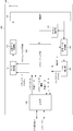
- FIG. 1 is a schematic block diagram showing a configuration of a base station apparatus according to the present embodiment.
- the base station apparatus 100 shown in FIG. 1 includes a primary base station and a secondary base station.
- the base station apparatus 100 includes a data control unit 101, a transmission data modulation unit 102, a radio unit 103, a scheduling unit 104, a channel estimation unit 105, a received data demodulation unit 106, a data extraction unit 107, and an upper layer. 108 and an antenna 109.
- Radio section 103, scheduling section 104, channel estimation section 105, reception data demodulation section 106, data extraction section 107, upper layer 108 and antenna 109 constitute a reception section.
- the data control unit 101, the transmission data modulation unit 102, the radio unit 103, the scheduling unit 104, the upper layer 108, and the antenna 109 constitute a transmission unit.
- each part which comprises the base station apparatus 100 is also called a unit.
- the data control unit 101 receives a transport channel from the scheduling unit 104.
- the data control unit 101 maps signals generated in the transport channel and the physical layer to the physical channel based on scheduling information input from the scheduling unit 104. Each mapped data is output to transmission data modulation section 102.
- the data control unit 101 maps the PDSCH to the resource element based on the resource element to which the physical signal / physical channel is mapped. For example, the data control unit 101 performs rate matching based on the position of the cell specific reference signal determined from the physical layer cell identity. Also, the data control unit 101 performs rate matching based on the position of the cell specific reference signal designated to the terminal.
- the transmission data modulation unit 102 modulates / encodes transmission data.
- the transmission data modulation unit 102 modulates / encodes the data input from the data control unit 101 based on scheduling information from the scheduling unit 104, serial / parallel conversion of the input signal, IFFT (Inverse Fast Fourier Transform). Conversion: Inverse Fase Fourier Transform (PC) processing, CP (Cyclic Prefix) insertion, and other signal processing are performed, transmission data is generated, and output to the wireless unit 103.
- PC Inverse Fase Fourier Transform
- CP Cyclic Prefix
- the radio unit 103 up-converts transmission data input from the transmission data modulation unit 102 to a radio frequency to generate a radio signal, and transmits the radio signal to the terminal via the antenna 109.
- Radio section 103 receives a radio signal received from the terminal via antenna 109, down-converts it to a baseband signal, and outputs received data to channel estimation section 105 and received data demodulation section 106.
- the scheduling unit 104 performs mapping between logical channels and transport channels, downlink and uplink scheduling, and the like. Since the scheduling unit 104 controls the processing units of each physical layer in an integrated manner, the scheduling unit 104, the antenna 109, the radio unit 103, the channel estimation unit 105, the reception data demodulation unit 106, the data control unit 101, the transmission data modulation An interface between the unit 102 and the data extraction unit 107 exists.
- the scheduling unit 104 In downlink scheduling, the scheduling unit 104 generates transmission control and scheduling information in the transport channel and physical channel based on uplink control information received from the terminal, scheduling information input from the higher layer 108, and the like. To do.
- the scheduling information used for downlink scheduling is output to the data control unit 101.
- the scheduling unit 104 In the uplink scheduling, the scheduling unit 104 generates scheduling information based on the uplink channel state output from the channel estimation unit 105, the scheduling information input from the higher layer 108, and the like. Scheduling information used for uplink scheduling is output to the data control unit 101.
- the scheduling unit 104 maps the downlink logical channel input from the higher layer 108 to the transport channel, and outputs it to the data control unit 101. Also, the scheduling unit 104 processes the uplink transport channel and control data input from the data extraction unit 107 as necessary, maps them to the uplink logical channel, and outputs them to the upper layer 108.
- the channel estimation unit 105 estimates an uplink channel state from an uplink reference signal (for example, a demodulation reference signal) and demodulates the signal transmitted on the uplink, and outputs it to the reception data demodulation unit 106 . Further, in order to perform uplink scheduling, an uplink channel state is estimated from an uplink reference signal (for example, a sounding reference signal), and is output to the scheduling section 104.
- an uplink reference signal for example, a sounding reference signal
- Received data demodulator 106 demodulates received data. Based on the uplink channel state estimation result input from the channel estimation unit 105, the reception data demodulation unit 106 performs DFT conversion, subcarrier mapping, IFFT conversion, etc. on the modulation data input from the radio unit 103. Signal processing is performed, demodulation processing is performed, and the data is output to the data extraction unit 107.
- the data extraction unit 107 confirms whether or not the received data input from the received data demodulation unit 106 is correct and outputs a confirmation result (for example, ACK or NACK) to the scheduling unit 104.
- the data extraction unit 107 separates the data input from the reception data demodulation unit 106 into a transport channel and physical layer control data, and outputs the separated data to the scheduling unit 104.
- the upper layer 108 performs processing of a radio resource control (RRC) layer and processing of a MAC (Media Access Control) layer.
- RRC radio resource control
- MAC Media Access Control
- the upper layer 108 integrates and controls the processing units of the lower layer, so the upper layer 108, the scheduling unit 104, the antenna 109, the radio unit 103, the channel estimation unit 105, the received data demodulation unit 106, the data control unit 101, There is an interface between the transmission data modulation unit 102 and the data extraction unit 107.
- RRC radio resource control
- MAC Media Access Control
- FIG. 2 is a schematic block diagram showing the configuration of the terminal device according to the present embodiment.
- the terminal device 200 includes a data control unit 201, a transmission data modulation unit 202, a radio unit 203, a scheduling unit 204, a channel estimation unit 205, a reception data demodulation unit 206, a data extraction unit 207, and an upper layer 208. And an antenna 209.
- the data control unit 201, transmission data modulation unit 202, radio unit 203, scheduling unit 204, upper layer 208, and antenna 209 constitute a transmission unit.
- the radio unit 203, scheduling unit 204, channel estimation unit 205, reception data demodulation unit 206, data extraction unit 207, higher layer 208, and antenna 209 constitute a reception unit.
- each part which comprises the terminal device 200 is also called a unit.
- the data control unit 201 receives the transport channel from the scheduling unit 204. Further, the data control unit 201 maps signals generated in the transport channel and the physical layer to the physical channel based on the scheduling information input from the scheduling unit 204. Each mapped data is output to transmission data modulation section 202.
- the transmission data modulation unit 202 modulates / encodes transmission data.
- Transmission data modulation section 202 performs signal processing such as modulation / coding, input signal serial / parallel conversion, IFFT processing, CP insertion on the data input from data control section 201 to generate transmission data.
- signal processing such as modulation / coding, input signal serial / parallel conversion, IFFT processing, CP insertion on the data input from data control section 201 to generate transmission data.
- the radio unit 203 up-converts the transmission data input from the transmission data modulation unit 202 to a radio frequency to generate a radio signal, and transmits the radio signal to the base station via the antenna 209.
- Radio section 203 receives a radio signal received from the base station via antenna 209, down-converts it to a baseband signal, and outputs the received data to channel estimation section 205 and received data demodulation section 206. .
- the scheduling unit 204 performs mapping between logical channels and transport channels, downlink and uplink scheduling, and the like. Since the scheduling unit 204 controls the processing units of each physical layer in an integrated manner, the scheduling unit 204, the antenna 209, the data control unit 201, the transmission data modulation unit 202, the channel estimation unit 205, the reception data demodulation unit 206, the data There is an interface between the extraction unit 207 and the wireless unit 203.
- the scheduling unit 204 performs reception control and generation of scheduling information in the transport channel and the physical channel based on downlink control information received from the base station, scheduling information input from the higher layer 208, and the like.
- the scheduling information used for downlink scheduling is output to the data control unit 201.
- the scheduling unit 204 maps the uplink logical channel input from the upper layer 208 to the transport channel based on downlink control information received from the base station, scheduling information input from the upper layer 208, and the like. Scheduling information for generation and scheduling information used for uplink scheduling is generated. The scheduling information is output to the data control unit 201.
- the scheduling unit 204 maps the uplink logical channel input from the higher layer 208 to the transport channel, and outputs it to the data control unit 201.
- the scheduling unit 204 also includes channel state information input from the channel estimation unit 205 and CRC (Cyclic Redundancy Check) parity bits (also simply referred to as CRC) input from the data extraction unit 207.
- CRC Cyclic Redundancy Check
- the confirmation result is also output to the data control unit 201.
- the channel estimation unit 205 estimates a downlink channel state from the downlink reference signal and demodulates the signal transmitted on the downlink, and outputs it to the reception data demodulation unit 206.
- Received data demodulation section 206 demodulates the received data input from radio section 203 and outputs the demodulated data to data extraction section 207.
- the reception data demodulation unit 206 receives the PDSCH mapped to the resource element based on the resource element to which the physical signal / physical channel is mapped (also described as demapping the PDSCH from the resource element). For example, the reception data demodulation unit 206 receives the downlink data assuming that rate matching has been performed based on the position of the cell specific reference signal determined from the physical layer cell identity. Received data demodulation section 206 receives downlink data on the assumption that rate matching has been performed based on the position or resource element of the cell specific reference signal designated by the base station apparatus.
- the data extraction unit 207 confirms the correctness of the reception data input from the reception data demodulation unit 206 and outputs a confirmation result (for example, ACK or NACK) to the scheduling unit 204. Further, the data extraction unit 207 separates the reception data input from the reception data demodulation unit 206 into transport channel and physical layer control data, and outputs the data to the scheduling unit 204.
- a confirmation result for example, ACK or NACK
- the upper layer 208 performs processing of the radio resource control layer and processing of the MAC layer.
- the upper layer 208 integrates and controls the processing units of the lower layer, so that the upper layer 208, the scheduling unit 204, the antenna 209, the data control unit 201, the transmission data modulation unit 202, the channel estimation unit 205, the reception data demodulation unit 206, an interface between the data extraction unit 207 and the wireless unit 203 exists.
- FIG. 3 is a schematic diagram illustrating an example of a wireless communication system according to the present embodiment.
- the terminal device 303 can perform single cell communication with the primary base station device 301 or the secondary base station 302.
- the terminal device 303 can perform multicell communication with the primary base station 301 and / or the secondary base station 302.
- single-cell communication indicates that a single base station device transmits downlink information (downlink signal) to a terminal device.
- the terminal device 303 can receive downlink information transmitted from the primary base station 301 on the downlink 304 in a certain subframe. Also, the terminal device 303 can receive downlink information transmitted from the secondary base station 302 via the downlink 305 in another subframe.
- multi-cell communication indicates that a plurality of base station apparatuses cooperate with each other to transmit downlink information to a terminal apparatus.
- the terminal device 303 receives downlink information transmitted from the primary base station 301 on the downlink 304 and downlink information transmitted from the secondary base station 302 on the downlink 305 in the same subframe. be able to.
- the terminal device 303 transmits downlink information transmitted from the primary base station 301 on the downlink 304 or transmitted from the secondary base station 302 on the downlink 305 as in dynamic point selection described later. Downlink information can be received in the same subframe. In multi-cell communication in which dynamic point selection is performed, the terminal device 303 can perform reception processing without recognizing which base station device (transmission point) is transmitting downlink information.
- multi-cell communication includes a CoMP transmission method. More specifically, joint transmission (JT: Joint transmission, Joint processing) in which the same downlink information is transmitted from a plurality of base station apparatuses is included. Also included is dynamic point selection (DPS), which dynamically switches base station apparatuses that transmit downlink information. In addition, coordinated beamforming (CB) that reduces interference by performing beamforming in cooperation between base station apparatuses is included. In addition, coordinated scheduling (CS) that reduces interference by performing coordinated scheduling between base station apparatuses is included.
- JT Joint transmission, Joint processing
- DPS dynamic point selection
- CB coordinated beamforming
- CS coordinated scheduling
- the terminal device 303 when joint transmission is used as multi-cell communication, the terminal device 303 has downlink information transmitted on the downlink 304 and downlink information transmitted on the downlink 305. Receive in subframe. Also, when dynamic point selection is used for multicell communication, the terminal device 303 transmits downlink information transmitted on the downlink 304 or downlink information transmitted on the downlink 305 to a certain sub Receive in frames.
- communication between base station apparatuses (for example, exchange of control information for performing multi-cell communication or single-cell communication) is performed through the line 306.
- a wired line such as an optical fiber or a wireless line such as a relay is used.
- different physical layer cell identities may be set for the primary base station 301 and the secondary base station 302. Further, the same physical layer cell identity may be set for all or part of the primary base station 301 and the secondary base station 302.
- the downlink information includes downlink data (downlink shared channel (DL-SCH)). Also, the downlink information includes information (Multicast Channel (MCH)) related to MBMS (Multimedia Broadcast and Multicast Service). Also, the downlink information includes downlink control information (DCI; Downlink Control Information).
- DL-SCH downlink shared channel
- MCH Multicast Channel
- DCI Downlink Control Information
- DL-SCH and MCH are transport channels.
- a channel used in a medium access control (MAC) layer is referred to as a transport channel.
- the unit of the transport channel used in the MAC layer is also referred to as a transport block (Transport Block).
- the DL-SCH is mapped to a physical downlink shared channel (PDSCH; Physical Downlink Shared Channel). That is, PDSCH is used for transmitting downlink data.
- PDSCH Physical Downlink Shared Channel
- the MCH is mapped to a physical multicast channel (PMCH; Physical Multiset Channel). That is, the PMCH is used to transmit information related to MBMS.
- PMCH Physical Multiset Channel
- the downlink control information is mapped to a physical downlink control channel (PDCCH; Physical Downlink Control Channel). That is, PDCCH is used for transmitting downlink control information.
- PDCCH Physical Downlink Control Channel
- the downlink control information may be mapped to an enhanced physical downlink control channel (E-PDCCH; Enhanced Physical Downlink Channel, enhanced PDCCH). That is, the E-PDCCH is used for transmitting downlink control information.
- E-PDCCH enhanced Physical Downlink Control channel
- enhanced PDCCH Enhanced Physical Downlink Channel
- the base station device when transmitting the downlink information to the terminal device, the base station device multiplexes a downlink reference signal (DRS; Downlink Reference Signals) that is a known signal between the base station device and the terminal device.
- DRS Downlink Reference Signal
- the following four types are defined as downlink reference signals.
- the downlink reference signal is a physical signal.
- a cell-specific reference signal (CRS: Cell-specific Reference Signals, also called a cell-specific reference signal) is defined as a downlink reference signal.
- the cell-specific reference signal is also referred to as a common reference signal (CRS; Common Reference Signals).
- the cell specific reference signal is used by the terminal device to synchronize the downlink frequency domain and time domain. Further, the cell specific reference signal is used to perform propagation path correction for the PDCCH. Further, the cell specific reference signal is used for performing propagation path correction for the PDSCH. Further, the cell specific reference signal is used by the terminal device to calculate downlink channel state information.
- the cell specific reference signal is transmitted to a plurality of terminal devices. Further, the cell specific reference signal is transmitted over the entire band in the downlink. In addition, the cell specific reference signal is transmitted in all downlink subframes that support PDSCH transmission.
- a user equipment specific reference signal (URS; User Equipment-specific Reference Signals, also referred to as a terminal apparatus specific reference signal) is defined as a downlink reference signal.
- URS User Equipment-specific Reference Signals
- DMRS Demodulation Reference Signal
- the user apparatus specific reference signal is used by the terminal apparatus to perform propagation path correction for the E-PDCCH. Further, the user apparatus specific reference signal is used by the terminal apparatus for performing propagation path correction on the PDSCH. Further, the user apparatus specific reference signal is transmitted for a specific terminal apparatus. Further, the user apparatus specific reference signal is transmitted only in the resource block used for transmission of the PDSCH intended for the corresponding terminal apparatus.
- the user apparatus specific reference signal associated with the E-PDCCH may be different from the user apparatus specific reference signal associated with the PDSCH.
- the antenna port used in the user equipment specific reference signal associated with the E-PDCCH may be different from the antenna port used in the user equipment specific reference signal associated with the PDSCH.
- an MBSFN reference signal (MBSFN RS; Multicast / Broadcast over Signal Frequency Network Reference Signals) is defined as a downlink reference signal.
- the MBSFN reference signal is used for the terminal apparatus to perform propagation path correction on the PMCH.
- the MBSFN reference signal is transmitted for a plurality of terminal devices.
- the MBSFN reference signal is transmitted over the entire band in the downlink.
- the MBSFN reference signal is transmitted in a subframe set as an MBSFN subframe by using a higher layer signal by the base station apparatus.
- the base station apparatus can set a subset of downlink subframes in a radio frame as an MBSFN subframe.
- the MBSFN subframe indicates a subframe reserved for the MBSFN subframe.
- the MBSFN subframe is indicated for each serving cell based on a parameter (hereinafter, also referred to as information on the MBSFN subframe) transmitted by the base station apparatus using a higher layer signal.
- the downlink subframe that is not set as the MBSFN subframe in the radio frame is referred to as a non-MBSFN subframe or a unicast subframe.
- the base station apparatus can perform transmission on the PDSCH and cannot perform transmission on the PMCH. Moreover, the base station apparatus can perform transmission by PDSCH or transmission by PMCH in the MBSFN subframe.
- the terminal apparatus decodes the PDSCH in the MBSFN subframe other than the subframe instructed to decode the PMCH using the higher layer signal.
- each MBSFN subframe is divided into a non-MBSFN area and an MBSFN area.
- the non-MBSFN region is composed of the first one or two OFDM symbols in the MBSFN subframe.
- the MBSFN region is composed of OFDM symbols that are not used as non-MBSFN regions in the MBSFN subframe.
- the non-MBSFN area is an area that is not reserved for MBSFN.
- the MBSFN area is an area reserved for MBSFN. That is, PMCH is transmitted only in the MBSFN region in a certain MBSFN subframe. PDSCH is transmitted only in the MBSFN region in a certain MBSFN subframe.
- CSI-RS channel state information reference signal
- the channel state information reference signal is used by the terminal device to calculate downlink channel state information.
- the channel state information reference signal is transmitted only in the band set by the base station apparatus.
- aggregation of a plurality of serving cells is supported in the downlink and uplink (Carrier Aggregation (CA) or Cell Aggregation (CA)).
- CA Carrier Aggregation
- CA Cell Aggregation
- one serving cell is defined as a primary cell (Pcell).
- Pcell primary cell
- Scell secondary cell
- the serving cell may be defined as one serving cell (cell) including a primary cell for a terminal for which CA is not set.
- the serving cell may be defined as a set of (one or) a plurality of saving cells (cells) including a primary cell and a secondary cell for a terminal for which CA is set.
- the carrier corresponding to the serving cell in the downlink is defined as a downlink component carrier (DLCC).
- a carrier corresponding to a primary cell in the downlink is defined as a downlink primary component carrier (DLPCC; Downlink Primary Component Carrier).
- DLPCC Downlink Primary Component Carrier
- a carrier corresponding to a secondary cell in the downlink is defined as a downlink secondary component carrier (DLSCC; Downlink Secondary Component Carrier).
- the carrier corresponding to the serving cell in the uplink is defined as an uplink component carrier (ULCC).
- a carrier corresponding to a primary cell in the uplink is defined as an uplink primary component carrier (ULPCC; Uplink Primary Component Carrier).
- a carrier corresponding to a secondary cell in the uplink is defined as an uplink secondary component carrier (ULSCCC; Uplink Secondary Component Carrier).
- a primary cell is defined as a cell in which a terminal device performs an initial connection establishment procedure.
- the primary cell is defined as a cell from which the terminal device starts a connection re-establishment procedure.
- a primary cell is defined as a cell indicated as a primary cell by a base station apparatus during a handover procedure.
- the base station apparatus and the terminal apparatus can perform transmission / reception on a plurality of physical channels in a certain subframe.
- each of the physical channels is mapped to any one serving cell. That is, a single physical channel is not mapped to multiple serving cells.
- FIG. 4 is a diagram illustrating an example of physical downlink channel mapping.
- FIG. 4 shows a PDCCH resource region, an E-PDCCH resource region, a PDSCH resource region, and a PMCH resource region.
- a common search space (CSS; Common Search Space, common search space)
- a user device specific search space (USS; UE-Specific Search Space, a search space unique to a terminal device) are shown.
- the PDSCH is mapped to an OFDM symbol (which may be an OFDM symbol resource element) to which the PDCCH is not mapped in the non-MBSFN subframe.
- the PDSCH is mapped to an OFDM symbol to which no PDCCH is mapped in the MBSFN subframe.
- PMCH is mapped to the MBSFN area in the MBSFN subframe.
- a single PMCH is transmitted in a certain subframe.
- the PDCCH is mapped to the 0th, 1st and 2nd OFDM symbols in the non-MBSFN subframe. Also, for example, the PDCCH is mapped to the 0th and 1st OFDM symbols in the MBSFN subframe.
- the PDCCH can be time division multiplexed (TDM) with the PDSCH.
- the base station apparatus transmits information on the OFDM symbol used for PDCCH transmission to a terminal apparatus using a physical control format indication channel (PCFICH; Physical Control Format Channel) in a certain subframe. Can be directed.
- the PDCCH may be transmitted using the same antenna port as the antenna port used for transmitting the cell specific reference signal.
- E-PDCCH is mapped to an OFDM symbol in which PDCCH is not mapped in a certain subframe. Further, the E-PDCCH can be frequency division multiplexed (FDM) with the PDSCH.
- FDM frequency division multiplexed
- the base station apparatus can set the E-PDCCH resource region to the terminal apparatus using a higher layer signal.
- the E-PDCCH may be transmitted using the same or different antenna port as the antenna port used for transmitting the user apparatus specific reference signal associated with the PDSCH.
- the user apparatus specific reference signal may be shared by a plurality of terminal apparatuses.
- E-PDCCH is basically included in PDCCH.
- DCI format Downlink control information format
- DCI format 1A used for scheduling one PDSCH (one PDSCH codeword, one downlink transport block transmission) in one cell is defined.
- DCI format 2 (DCI format used for scheduling of one PDSCH (up to two PDSCH codewords, transmission of up to two downlink transport blocks) in one cell) 2C may be defined).
- a DCI format for the downlink a DCI format (DCI format X) used for scheduling for multi-cell communication may be defined.
- the DCI format for the downlink includes downlink control information such as information related to PDSCH resource allocation and information related to MCS (Modulation and Coding scheme).
- the DCI format used for PDSCH scheduling is also referred to as downlink assignment.
- DCI format for uplink scheduling of one physical uplink shared channel (PUSCH) in one cell (transmission of one PUSCH codeword, one uplink transport block) DCI format 0 used for the above is defined.
- PUSCH physical uplink shared channel
- DCI format 4 used for scheduling of one PUSCH (up to two PUSCH codewords, transmission of up to two uplink transport blocks) in one cell is defined.
- a DCI format (DCI format Y) used for multi-cell communication scheduling may be defined as a DCI format for uplink.
- the DCI format for the uplink includes downlink control information such as information on PUSCH resource allocation and information on MCS (Modulation and Coding scheme).
- the DCI format used for PUSCH scheduling is also referred to as an uplink grant.
- the terminal apparatus monitors a set of PDCCH candidates (PDCCH candidates).
- PDCCH candidates indicates a candidate that may be mapped and transmitted by the base station apparatus.
- the PDCCH candidate is configured by one or a plurality of control channel elements (CCE).
- monitoring means that the terminal device attempts to decode each PDCCH in the set of PDCCH candidates according to all the DCI formats to be monitored.
- the terminal apparatus monitors a set of E-PDCCH candidates (E-PDCCH candidates).
- E-PDCCH candidates indicates a candidate that the E-PDCCH may be mapped and transmitted by the base station apparatus.
- the E-PDCCH candidate is composed of one or a plurality of control channel elements (E-CCE; Enhanced Control Channel Element).
- monitoring means that the terminal device attempts to decode each E-PDCCH in the set of E-PDCCH candidates according to all the DCI formats to be monitored.
- the set of PDCCH candidates and / or the set of E-PDCCH candidates monitored by the terminal device is also called a search space. That is, the search space is a set of resources that may be used by the base station apparatus for PDCCH transmission and / or E-PDCCH transmission.
- CSS and / or USS is configured (defined or set) in the PDCCH resource area. Also, CSS and / or USS are configured (defined and set) in the resource area of E-PDCCH.
- the base station apparatus transmits (arranges) the PDCCH in the CSS and / or USS of the PDCCH resource region. Further, the base station apparatus transmits (arranges) the E-PDCCH in the CSS and / or USS of the E-PDCCH resource region.
- the terminal apparatus monitors the PDCCH in the CSS and / or USS of the PDCCH resource area, and detects the PDCCH addressed to itself. Further, the terminal apparatus monitors the E-PDCCH in the CSS and / or USS of the E-PDCCH resource area, and detects the E-PDCCH addressed to the terminal apparatus.
- CSS is used for transmission of downlink control information to a plurality of terminal apparatuses. That is, CSS is defined by resources common to a plurality of terminal devices.
- the CSS is configured by CCEs having numbers defined in advance between the base station apparatus and the terminal apparatus (for example, CCEs having indexes from 0 to 15).
- CSS may be used for transmission of downlink control information to a specific terminal device. That is, the base station apparatus can transmit a DCI format targeted for a plurality of terminal apparatuses and / or a DCI format targeted for a specific terminal apparatus in CSS.
- USS is used for transmission of downlink control information to a specific terminal device. That is, USS is defined by a resource dedicated to a certain terminal device. That is, USS is defined independently for each terminal device.
- the USS is composed of a radio network temporary identifier (RNTI; Radio Network Temporary Indentifier) assigned by the base station apparatus, a slot number in a radio frame, and a CCE with a number determined based on an aggregation level. That is, the base station apparatus transmits a DCI format intended for a specific terminal apparatus in USS.
- RNTI Radio Network Temporary Indentifier
- RNTI assigned by the base station apparatus to the terminal apparatus is used for transmission of downlink control information (transmission on PDCCH, transmission on E-PDCCH).
- CRC Cyclic Redundancy Check; cyclic redundancy check parity bit (also simply referred to as CRC)) generated based on downlink control information (which may be a DCI format) is added to the downlink control information.
- the CRC parity bit is scrambled with RNTI.
- the terminal device attempts to decode the PDCCH with CRC parity bits scrambled by the RNTI (E-PDCCH, downlink control information, or DCI format may be used), and the PDCCH for which CRC was successful is transmitted to the own device Detect as PDCCH (also called blind decoding).
- E-PDCCH CRC parity bits scrambled by the RNTI
- DCI format downlink control information
- PDCCH also called blind decoding
- RNTI includes C-RNTI (Cell RNTI).
- the RNTI includes RA-RNTI (Random Access RNTI).
- the RNTI includes P-RNTI (Paging RNTI).
- the RNTI includes SI-RNTI (System Information RNTI).
- C-RNTI is a unique (unique) identifier used for RRC (Radio Resource Control, radio resource control) connection and scheduling identification.
- RRC Radio Resource Control, radio resource control
- C-RNTI is utilized for dynamically scheduled unicast transmissions.
- RA-RNTI is an identifier used when a random access response message is transmitted in a random access procedure. For example, when transmitting a random access preamble, the terminal device monitors the PDCCH with the CRC scrambled by the RA-RNTI.
- the terminal device executes a random access procedure in order to establish an initial connection (initial connection establishment). Further, the terminal device executes a random access procedure for handover. Further, the terminal device executes a random access procedure for connection re-establishment (connection re-eatability). Further, the terminal apparatus executes a random access procedure in order to request a UL-SCH resource.
- the P-RNTI is an identifier used for notification of paging and system information.
- SI-RNTI is an identifier used for broadcasting system information.
- the PDCCH with CRC scrambled by C-RNTI may be transmitted by USS or CSS. Further, the PDCCH with CRC scrambled by RA-RNTI may be transmitted only by CSS. Also, the PDCCH with CRC scrambled by P-RNTI may be transmitted only by CSS. Also, the PDCCH with CRC scrambled by SI-RNTI may be transmitted only by CSS.
- the terminal device changes the interpretation of the downlink control information based on which RNTI the CRC is scrambled with.
- the terminal apparatus receives downlink data on the PDSCH scheduled using the downlink control information transmitted on the PDCCH.
- transmission of downlink data on the PDSCH is also referred to as PDSCH transmission.
- reception of downlink data on the PDSCH is also referred to as PDSCH reception.
- the base station device and the terminal device transmit and receive signals in an upper layer (Higher layer).
- a base station apparatus and a terminal apparatus are also referred to as a radio resource control signal (RRC signaling; RRC signaling; Radio Resource Control signal, RRC message; Radio Resource Control message, RRC information; Radio Resource control call in the RRC layer (layer 3). ).
- a dedicated signal transmitted to a certain terminal device by the base station device is also referred to as a dedicated signal (dedicated signal). That is, a dedicated (unique) setting (information) for a certain terminal device is transmitted by the base station device using a dedicated signal.
- the dedicated signal is included in the RRC signaling.
- the base station device and the terminal device transmit and receive MAC control elements in a MAC (Media Access Control) layer (layer 2).
- MAC Media Access Control
- the RRC signaling and / or the MAC control element is also referred to as an upper layer signal (higher layer signaling).
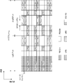
- FIG. 5 is a diagram illustrating an example of mapping between PDSCH and a downlink reference signal.
- FIG. 5 illustrates an example of downlink reference signal mapping in a non-MBSFN subframe.
- FIG. 5 shows two resource blocks (also referred to as resource block pairs) in one subframe.
- one resource block is composed of 12 subcarriers in the frequency domain and 7 OFDM symbols in the time domain.
- each of the 7 OFDM symbols in the time domain is also referred to as a slot. That is, one subframe is composed of a first slot and a second slot.
- a resource minimum time-frequency constituent unit defined by one OFDM symbol and one subcarrier is also called a resource element. That is, the PDSCH is mapped to the resource element. Also, the downlink reference signal is mapped to the resource element.
- the antenna ports of the user equipment specific reference signal associated with the PDSCH are 7-14.
- antenna ports of user apparatus specific reference signals associated with E-PDCCH are 107-110.
- the user apparatus specific reference signal in each antenna port is generated using an orthogonal code sequence having a code length of 2 or 4, and is mapped to a resource element of any DMRS group.
- the antenna ports of the channel state information reference signal are 15-22.
- the channel state information reference signal in each antenna port is generated using an orthogonal code sequence having a code length of 2, and is mapped to a resource element of any CSI-RS group.
- FIG. 6 is another diagram showing an example of mapping between PDSCH and downlink reference signals.
- FIG. 6 illustrates an example of downlink reference signal mapping in the MBSFN subframe.
- the cell specific reference signal is not transmitted in the MBSFN area of the MBSFN subframe. That is, in a certain MBSFN subframe, the cell specific reference signal is transmitted only in the non-MBSFN region of the MBSFN subframe.
- a user apparatus specific reference signal is transmitted in the MBSFN area of a certain MBSFN subframe. Also, in the MBSFN area of a certain MBSFN subframe, when the PMCH is transmitted, an MBSFN reference signal is transmitted.
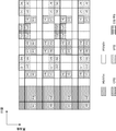
- FIG. 7 is another diagram showing an example of mapping between PDSCH and downlink reference signals.
- FIG. 7 shows an example of mapping of downlink reference signals transmitted in each of two cells.
- the left side of FIG. 7 shows an example of mapping of downlink reference signals transmitted in a certain cell (cell 1).
- the right side of FIG. 7 illustrates an example of mapping of a downlink reference signal transmitted in a cell (cell 2) with a physical layer cell identity different from the physical layer cell identity for cell 1.
- the cell 2 shown on the right side of FIG. 7 can be considered as an adjacent cell to the cell 1 (also referred to as another cell, a coordinated cell, or an associated cell).
- the terminal device can assume (identify and recognize) each downlink reference signal as shown in FIG. That is, for example, the terminal apparatus receives each PDSCH based on the respective positions of the two cell-specific reference signals.
- the position of the cell-specific reference signal (hereinafter also referred to as CRS position) is determined (calculated) based on the physical layer cell identity (physical layer cell identity value).
- the position of the cell specific reference signal is also described as a resource element (position of the resource element) to which the cell specific reference signal is mapped.
- the location of the cell specific reference signal in cell 1 is determined based on the physical layer cell identity for cell 1. Further, the position of the cell specific reference signal in the cell 2 is determined based on the physical layer cell identity for the cell 2. That is, as shown in FIG. 7, in each cell (cell 1, cell 2) with different physical layer cell identities, cell specific reference signals are mapped to different positions.
- the position of the cell specific reference signal is determined by specifying the position of the resource element to which the cell specific reference signal is mapped based on the physical layer cell identity. Also, for example, the position of the cell specific reference signal is shifted in the frequency direction based on the physical layer cell identity. Further, for example, the position of the cell specific reference signal is determined in three patterns with respect to the frequency direction based on the physical layer cell identity.
- the terminal device can detect the physical layer cell identity by using a synchronization signal (Synchronization signals).
- the terminal device can acquire the physical layer cell identity from information included in an upper layer signal (for example, a bandover command) transmitted by the base station device.
- FIG. 8 is another diagram showing an example of mapping between PDSCH and downlink reference signals.
- FIG. 8 illustrates an example of mapping of downlink reference signals transmitted from two cells.
- cell 1 and cell 2 shown in FIG. 8 correspond to FIG.
- the terminal apparatus can assume (identify and recognize) a downlink reference signal as illustrated in FIG. That is, the terminal apparatus receives the PDSCH based on the positions of the two cell specific reference signals.
- the PDSCH Rate-matching is performed on the resource element to which the signal / physical channel is mapped.
- the rate matching indicates, for example, a process of mapping PDSCH so as to avoid resource elements to which physical signals / physical channels other than PDSCH are mapped.
- a puncture punctcture process in which a physical element / physical channel other than the PDSCH is overwritten and mapped to a resource element to which the PDSCH is mapped.
- PDSCH is mapped to resource elements excluding resource elements to which physical signals / physical channels other than PDSCH are mapped. That is, the PDSCH is mapped to resource elements that are not used for physical signals / physical channels other than the PDSCH.
- the base station apparatus and the terminal apparatus perform transmission / reception on the PDSCH based on resource elements to which physical signals / physical channels other than the PDSCH are mapped in order to avoid deterioration of reception characteristics for the PDSCH.
- the base station apparatus may rate match the PDSCH based on the positions of the three cell specific reference signals. Further, the terminal apparatus may receive the PDSCH based on the positions of the three cell specific reference signals.
- the base station apparatus can specify (set or instruct) the position of the cell specific reference signal to the terminal.
- the base station apparatus can independently designate each position of one or more cell specific reference signals (for example, each position of three cell specific reference signals). That is, the base station apparatus can designate to the terminal apparatus resource elements (resource element positions) that can be used for PDSCH transmission.
- the position of the cell specific reference signal may be determined based on the frequency shift (position in the frequency direction) of the cell specific reference signal.
- the frequency shift of the cell specific reference signal is determined based on the physical layer cell identity.
- the position of the cell specific reference signal may be determined based on the number of ports used for transmitting the cell specific reference signal.
- the presence / absence of a cell specific reference signal may be determined based on whether it is an MBSFN subframe.
- the base station apparatus can specify the position of the cell-specific reference signal by transmitting information indicating the frequency shift of the cell-specific reference signal (for example, information on the physical layer cell identity). Moreover, the base station apparatus can designate the position of the cell specific reference signal by transmitting information indicating the number of ports of the cell specific reference signal.
- the base station apparatus can designate the presence / absence of the cell specific reference signal by transmitting information indicating a subframe in which the cell specific reference signal is transmitted (for example, information on the MBSFN subframe).
- information indicating the frequency shift of the cell-specific reference signal and / or information indicating the number of ports of the cell-specific reference signal and / or information indicating the subframe in which the cell-specific reference signal is transmitted are referred to the cell-specific reference. It is also described as information indicating the position of the signal.
- the base station apparatus can transmit the information indicating the position of the cell specific reference signal by including the information in the higher layer signal (which may be a dedicated signal). That is, the base station apparatus can specify a set of resource element positions to which the cell specific reference signal is mapped.
- the base station uses a higher layer signal (which may be a dedicated signal) to set a plurality of cell specific reference signal positions, and further uses the PDCCH to set a plurality of cell specific references. From the signal location, the location of one or more cell specific reference signals can be indicated.
- a higher layer signal which may be a dedicated signal
- the base station uses a higher layer signal (which may be a dedicated signal) to set a plurality of cell specific reference signal positions, and further uses PDCCH to enable or disable this setting. Can be directed.
- a higher layer signal which may be a dedicated signal
- the base station apparatus includes, in the DCI format (for example, downlink assignment) transmitted on the PDCCH, downlink control information (hereinafter also referred to as first control information) related to the position of the cell specific reference signal. Can be transmitted to the terminal device.
- a 2-bit field (or 3-bit field) defined in the DCI format is mapped to the first control information.
- the base station apparatus uses the remaining one state to use the position of the cell specific reference signal of the serving cell (that is, the position of the cell specific reference signal determined based on the physical layer cell identity). (For example, “00: position of cell-specific reference signal of serving cell”).
- the position of the (three) cell specific reference signals is specified using a bitmap format. be able to. That is, the combination of the positions of the three cell-specific reference signals can be indicated by associating the combination of the positions of the three cell-specific reference signals with each of the 3-bit fields.
- the first control information can be included in a DCI format other than a predetermined DCI format. That is, the first control information may not be included in the predetermined DCI format.
- the first control information may not be included in the DCI format 1A.
- a DCI format (predetermined DCI format) that can include the first control information is defined in advance by specifications or the like.
- the first control information can be included in the DCI format when the DCI format is transmitted in USS. That is, the first control information may not be included in the DCI format when the DCI format is transmitted by CSS.
- the first control information can be included in the DCI format 1A when the DCI format 1A is transmitted in USS. Also, the first control information may not be included in the DCI format 1A when the DCI format 1A is transmitted by CSS.
- the first control information may be included only in the DCI format transmitted only by the USS. That is, the first control information may not be included in the DCI format transmitted by CSS.
- the first control information can be included in the DCI format when the DCI format is transmitted on the PDCCH with the CRC scrambled with the C-RNTI. That is, the first control information may not be included in the DCI format when the DCI format is transmitted on the PDCCH accompanied by the CRC scrambled with RA-RNTI. Further, the first control information may not be included in the DCI format when the DCI format is transmitted on the PDCCH accompanied by the CRC scrambled with the P-RNTI. Further, the first control information may not be included in the DCI format when the DCI format is transmitted on the PDCCH accompanied by the CRC scrambled with the SI-RNTI.
- the first control information may be included in the DCI format only when set by the base station apparatus.
- the base station apparatus can transmit information instructing whether or not the first information is included in the DCI format by using an upper layer signal (which may be a dedicated signal).
- the first control information may be included in the DCI format only when a predetermined transmission mode (for example, a transmission mode for PDSCH) is set by the base station apparatus.
- a predetermined transmission mode for example, a transmission mode for PDSCH
- the base station apparatus can transmit the DCI format including the first information only when a predetermined transmission mode is set.
- the predetermined transmission mode is defined in advance by specifications or the like.
- the terminal can determine (estimate) the position of the cell-specific reference signal even when information regarding the frequency shift of the cell-specific reference signal is not transmitted.
- the terminal device can determine the position of the cell-specific reference signal on the assumption that the cell-specific reference signal is mapped to all resource elements to which the cell-specific reference signal may be mapped. Further, the terminal apparatus assumes that the cell specific reference signal is mapped to all resource elements to which the cell specific reference signal may be mapped except the resource element to which the cell specific reference signal of the serving cell is mapped. Thus, the position of the cell specific reference signal can be determined. Also, the terminal device can determine the position of the cell specific reference signal assuming that the position of the cell specific reference signal of each of the plurality of cells is the same as the position of the cell specific reference signal of the serving cell.
- how a terminal device assumes a resource element to which a cell specific reference signal is mapped is specified in advance by a specification or the like.
- the terminal device can determine (estimate) the position of the cell-specific reference signal even when information indicating the number of ports of the cell-specific reference signal is not transmitted.
- the terminal device can determine the position of the cell specific reference signal assuming the number of ports used for transmission of the cell specific reference signal. For example, the terminal device can determine the position of the cell-specific reference signal assuming that the number of ports used for transmitting the cell-specific reference signal is one port, two ports, or four ports. . Further, the terminal device assumes that the number of ports used for transmitting the cell specific reference signal of each of the plurality of cells is the same as the number of ports used for transmitting the cell specific reference signal of the serving cell. The position of the specific reference signal can be determined.
- how the terminal apparatus assumes the number of ports used for transmission of the cell specific reference signal is specified in advance by a specification or the like.
- the terminal device can determine (estimate) the position of the cell specific reference signal even when information indicating a subframe in which the cell specific reference signal is transmitted is not transmitted.
- the terminal device can determine the position of the cell specific reference signal assuming that the cell specific reference signal is transmitted in all subframes. Further, the terminal apparatus assumes that the subframe in which the cell specific reference signal of each of the plurality of cells is transmitted is the same as the subframe in which the cell specific reference signal of the serving cell is transmitted, and The position can be determined.
- how the terminal apparatus assumes a subframe in which a cell-specific reference signal is transmitted is defined in advance by a specification or the like.
- the base station apparatus performs rate matching based on only the position of the cell-specific reference signal determined from the physical layer cell identity of the serving cell, and transmits PDSCH (hereinafter also referred to as PDSCH based transmission based on PCI). To describe).
- the base station apparatus performs rate matching based on only the position of the cell specific reference signal determined from the physical layer cell identity for cell 1 and transmits the PDSCH. Further, as shown on the right side of FIG. 7, the base station apparatus performs rate matching based on only the position of the cell specific reference signal determined from the physical layer cell identity for cell 2, and transmits the PDSCH.
- the base station apparatus uses a user equipment specific setting (also described as a user-equipment specific configuration, a dedicated (unique) setting for a certain terminal apparatus) based on the position of the specified cell-specific reference signal. Rate matching is performed and the PDSCH is transmitted (hereinafter also referred to as PDSCH transmission based on the first setting).
- a user equipment specific setting also described as a user-equipment specific configuration, a dedicated (unique) setting for a certain terminal apparatus
- Rate matching is performed and the PDSCH is transmitted (hereinafter also referred to as PDSCH transmission based on the first setting).
- the base station apparatus performs rate matching based on the positions of the two cell-specific reference signals and transmits the PDSCH.
- the base station apparatus performs rate matching based on the position of the cell-specific reference signal transmitted in cell 1 and the position of the cell-specific reference signal transmitted in cell 2, and transmits the PDSCH.
- the base station apparatus performs rate matching based on the position of the cell specific reference signal determined from the physical layer cell identity of the serving cell and the position of the cell specific reference signal designated to the terminal apparatus, and transmits the PDSCH. good. That is, the base station apparatus performs rate matching based on the position of the cell specific reference signal specified to the terminal apparatus in addition to the position of the cell specific reference signal determined from the physical layer cell identity of the serving cell, and transmits the PDSCH. May be.
- rate matching is performed based on the position of the cell specific reference signal designated to the terminal device, and transmission is performed on the PDSCH.
- the transmission on the PDSCH based on the first setting is based on the position of the cell specific reference signal specified to the terminal device in addition to the position of the cell specific reference signal determined from the physical layer cell identity of the serving cell. This includes performing matching and performing transmission on the PDSCH. That is, transmission on the PDSCH based on the first setting includes at least rate matching based on the position of the cell specific reference signal designated to the terminal apparatus and transmission on the PDSCH.
- the terminal apparatus receives PDSCH assuming that the rate matching is performed based only on the position of the cell-specific reference signal determined from the physical layer cell identity of the serving cell (hereinafter referred to as PCI-based PDSCH). Also described as receiving).
- the terminal device assumes that PDSCH is performed based on the rate matching based on only the position of the cell specific reference signal determined from the physical layer cell identity for cell 1. Receive. Further, as shown on the right side of FIG. 7, the terminal apparatus assumes that the rate matching is performed based only on the position of the cell specific reference signal determined from the physical layer cell identity for the cell 2, and performs PDSCH. Receive.
- the terminal apparatus receives the PDSCH on the assumption that the rate matching is performed based on the position of the designated cell-specific reference signal using the user apparatus specific setting (hereinafter referred to as the first apparatus). Also described as reception on PDSCH based on configuration).
- the terminal device receives the PDSCH assuming that rate matching has been performed based on the positions of two cell-specific reference signals. For example, assuming that the rate matching is performed based on the position of the cell specific reference signal transmitted in cell 1 and the position of the cell specific reference signal transmitted in cell 2, the terminal apparatus receives the PDSCH.
- the terminal device assumes that rate matching is performed based on the position of the cell specific reference signal determined from the physical layer cell identity of the serving cell and the position of the cell specific reference signal specified by the base station.
- PDSCH may be received. That is, the terminal apparatus confirms that rate matching has been performed based on the position of the cell specific reference signal specified by the base station apparatus in addition to the position of the cell specific reference signal determined from the physical layer cell identity of the serving cell. Assuming PDSCH may be received.
- rate matching is performed based on the position of the cell-specific reference signal specified by the base station apparatus as reception on the PDSCH based on the first setting, It describes that reception by PDSCH is performed.
- reception on the PDSCH based on the first setting is based on the position of the cell specific reference signal specified by the base station apparatus in addition to the position of the cell specific reference signal determined from the physical layer cell identity of the serving cell. Assuming that rate matching is performed, reception on the PDSCH is included. That is, for reception on the PDSCH based on the first setting, reception on the PDSCH is assumed on the assumption that rate matching is performed based on at least the position of the cell specific reference signal specified by the base station apparatus. To do.
- FIG. 9 is a diagram illustrating an example of a flow according to the present embodiment.
- the base station apparatus switches between transmission on the PDSCH based on PCI and transmission on the PDSCH based on the first setting based on the condition.
- the terminal apparatus switches between reception on the PDSCH based on PCI and reception on the PDSCH based on the first setting.
- the base station apparatus when the condition is A, performs rate matching based on only the position of the cell specific reference signal determined from the physical layer cell identity of the serving cell, and transmits on the PDSCH.
- the base station apparatus maps the PDSCH to the resource element in the physical resource block allocated for transmission on the PDSCH. Further, when the condition is A, the base station apparatus maps the PDSCH to resource elements that are not used for transmission of the cell specific reference signal.
- the base station apparatus when the condition is B, the base station apparatus performs rate matching based on the position of the cell specific reference signal designated to the terminal apparatus, and performs transmission on the PDSCH.
- the base station apparatus maps the PDSCH to the resource elements in the physical resource block allocated for transmission on the PDSCH, excluding the resource elements designated to the terminal apparatus. Further, when the condition is B, the base station apparatus maps the PDSCH to resource elements that are not used for transmission of the cell specific reference signal.
- the terminal device assumes that rate matching is performed based only on the position of the cell specific reference signal determined from the physical layer cell identity of the serving cell, and receives the reception on the PDSCH. Do.
- the terminal apparatus receives the PDSCH mapped to the resource element in the physical resource block allocated for transmission on the PDSCH.
- the terminal apparatus receives PDSCH mapped to resource elements that are not used for transmission of the cell specific reference signal.
- the terminal apparatus performs reception on the PDSCH assuming that rate matching has been performed based on the position of the cell specific reference signal specified by the base station apparatus.
- the terminal device when the condition is B, the terminal device adds resource elements in the physical resource block allocated for transmission on the PDSCH, excluding resource elements specified (instructed or set) by the base station device. Receive the mapped PDSCH. That is, when the condition is A, the terminal apparatus receives the PDSCH mapped to the resource element that is not used for the transmission of the cell specific reference signal.
- condition A includes transmitting (arranging) the PDCCH in the CSS.
- Condition A includes detecting (decoding, receiving) the PDCCH in the CSS.
- the base station apparatus performs transmission on the PDSCH based on PCI when transmitting (or arranging) the PDCCH in the CSS.
- the terminal apparatus detects the PDCCH in the CSS, the terminal apparatus performs reception on the PDSCH based on the PCI.
- condition B includes transmitting (arranging) the PDCCH in the USS.
- Condition B includes detecting (decoding, receiving) the PDCCH in the USS.
- the base station apparatus when transmitting a PDCCH in USS, the base station apparatus performs transmission on the PDSCH based on the first setting. Further, when the terminal apparatus detects the PDCCH in the CSS, the terminal apparatus performs reception on the PDSCH based on the first setting.
- condition A includes transmitting a predetermined DCI format (hereinafter also referred to as a first DCI format). Further, the condition A includes that a predetermined DCI format is detected (decoded and received).
- the first DCI format is defined in advance by specifications or the like, and can be known information between the base station apparatus and the terminal apparatus.
- the first DCI format indicates the DCI format 1A.
- a new DCI format may be defined as the first DCI format.
- the DCI format 1A can be transmitted on the PDCCH in CSS and / or USS.
- the base station apparatus when transmitting the first DCI format (for example, DCI format 1A), the base station apparatus performs transmission on the PDSCH based on PCI. Further, when receiving the first DCI format (for example, DCI format 1A), the terminal device performs reception on the PDSCH based on PCI.
- the first DCI format for example, DCI format 1A
- condition B includes transmission of a DCI format other than the predetermined DCI format (hereinafter also referred to as a second DCI format or a DCI format different from the predetermined DCI format).
- the condition B includes detecting (decoding, receiving) a DCI format other than a predetermined DCI format.
- the second DCI format indicates a DCI format other than the DCI format 1A.
- the second DCI format includes DCI format 2 (or DCI format 2C).
- the second DCI format includes DCI format X.
- a new DCI format may be defined as the second DCI format.
- the base station apparatus when transmitting a second DCI format (for example, a DCI format other than the DCI format 1A), the base station apparatus performs transmission on the PDSCH based on the first setting. Further, when receiving the second DCI format (for example, a DCI format other than the DCI format 1A), the terminal device performs reception on the PDSCH based on the first setting.
- a second DCI format for example, a DCI format other than the DCI format 1A
- the terminal device when receiving the second DCI format (for example, a DCI format other than the DCI format 1A), the terminal device performs reception on the PDSCH based on the first setting.
- condition A includes transmitting (arranging) the first DCI format in the CSS.
- the condition A includes detecting (decoding, receiving) the first DCI format in the CSS. That is, for example, the condition A includes transmitting the DCI format 1A in CSS. Further, the condition A includes that the DCI format 1A is received in the CSS.
- the base station apparatus when transmitting the first DCI format (for example, DCI format 1A) in CSS, the base station apparatus performs transmission on the PDSCH based on PCI. Further, when receiving the first DCI format (for example, DCI format 1A) in the CSS, the terminal device performs reception on the PDSCH based on the PCI.
- the first DCI format for example, DCI format 1A
- the terminal device when receiving the first DCI format (for example, DCI format 1A) in the CSS, the terminal device performs reception on the PDSCH based on the PCI.
- condition B includes transmitting the first DCI format or the second DCI format in the USS.
- condition B includes transmitting the second DCI format in CSS.
- Condition B includes detecting (decoding, receiving) the first DCI format or the second DCI format in the USS.
- condition B includes detecting (decoding, receiving) the second DCI format in the CSS.
- the base station apparatus when the base station apparatus transmits the first DCI format (for example, DCI format 1A) or the second DCI format (for example, DCI format other than DCI format 1A) in the USS, the first setting is performed. Based on PDSCH. Further, when transmitting a second DCI format (for example, a DCI format other than the DCI format 1A) in the CSS, the base station apparatus performs transmission on the PDSCH based on the first setting.
- the first DCI format for example, DCI format 1A
- the second DCI format for example, DCI format other than DCI format 1A
- the terminal apparatus when the terminal apparatus receives the first DCI format (for example, DCI format 1A) or the second DCI format (for example, DCI format other than DCI format 1A) in the USS, the terminal apparatus sets the first setting. Based on PDSCH reception. Further, when receiving a second DCI format (for example, a DCI format other than the DCI format 1A) in the CSS, the terminal device performs reception on the PDSCH based on the first setting.
- the first DCI format for example, DCI format 1A
- the second DCI format for example, DCI format other than DCI format 1A
- condition A includes transmitting (arranging) the PDCCH accompanied by the CRC scrambled by the RA-RNTI.
- Condition A also includes transmitting a PDCCH with a CRC scrambled by P-RNTI.
- condition A includes transmitting a PDCCH with a CRC scrambled by SI-RNTI.
- condition A includes detecting (decoding and receiving) a PDCCH accompanied by a CRC scrambled by RA-RNTI.
- condition A includes detecting a PDCCH with a CRC scrambled by P-RNTI.
- condition A includes detecting a PDCCH with a CRC scrambled by SI-RNTI.
- the base station apparatus when transmitting a PDCCH with a CRC scrambled by RA-RNTI, the base station apparatus performs transmission on the PDSCH based on PCI. Also, when transmitting a PDCCH with a CRC scrambled by P-RNTI, the base station apparatus performs transmission on the PDSCH based on PCI. Further, when transmitting a PDCCH accompanied by a CRC scrambled by SI-RNTI, the base station apparatus performs transmission using PDSCH based on PCI.
- the terminal apparatus when the terminal apparatus detects a PDCCH with a CRC scrambled by RA-RNTI, the terminal apparatus performs reception on the PDSCH based on the PCI. In addition, when the terminal apparatus detects a PDCCH with a CRC scrambled by P-RNTI, the terminal apparatus performs reception on the PDSCH based on the PCI. Further, when the terminal apparatus detects a PDCCH with a CRC scrambled by SI-RNTI, the terminal apparatus performs reception on the PDSCH based on the PCI.
- condition B includes transmitting (arranging) the PDCCH accompanied by the CRC scrambled by the C-RNTI.
- the condition B includes detecting (decoding and receiving) a PDCCH accompanied by a CRC scrambled by C-RNTI.
- the base station apparatus transmits a PDCCH with a CRC scrambled by C-RNTI
- the base station apparatus performs transmission on the PDSCH based on the first setting.
- the terminal apparatus detects a PDCCH with a CRC scrambled by C-RNTI
- the terminal apparatus performs reception on the PDSCH based on the first setting.
- FIG. 10 is another diagram illustrating an example of a flow according to the present embodiment.
- the cell specific reference signal is transmitted only in the non-MBSFN region of the MBSFN subframe.
- the base station apparatus and the terminal apparatus correspond to cell 1 when cell 1 is a non-MBSFN subframe, cell 2 is an MBSFN subframe, and cell 3 is a non-MBSFN subframe.
- PDSCH transmission / reception may be performed based on the position of the cell-specific reference signal to be transmitted and the position of the cell-specific reference signal corresponding to cell 3.
- the base station apparatus and the terminal apparatus can determine whether a cell specific reference signal corresponding to a cell is based on whether a certain subframe is an MBSFN subframe or a non-MBSFN subframe. Whether to perform transmission / reception on the PDSCH based on the position can be switched.
- the base station apparatus switches operation (processing) according to conditions.
- the conditions condition A and condition B
- the base station apparatus identifies (recognizes and confirms) whether it is an MBSFN subframe or a non-MBSFN subframe in the serving cell.
- the base station apparatus performs transmission on the PDSCH without performing rate matching based on the position of the cell specific reference signal of the serving cell. That is, the base station apparatus performs transmission on the PDSCH without performing rate matching based on the position of the cell specific reference signal determined from the physical layer cell identity of the serving cell.
- the base station apparatus performs rate matching based only on the position of the cell specific reference signal of the serving cell and performs transmission on the PDSCH. That is, the base station apparatus performs transmission on the PDSCH based on PCI.
- the base station apparatus identifies (recognizes and confirms) whether the pattern is a MBSFN subframe or a non-MBSFN subframe in the pattern set for the terminal apparatus (that is, the MBSFN subframe pattern). ) As described above, the base station apparatus can set an MBSFN subframe (an MBSFN subframe pattern) by transmitting a parameter (for example, information on an MBSFN subframe) using a higher layer signal.
- a parameter for example, information on an MBSFN subframe
- the base station apparatus performs transmission on the PDSCH without performing rate matching based on the position of the designated cell specific reference signal. That is, the base station apparatus performs transmission on the PDSCH without performing rate matching based on the position of the designated cell specific reference signal using the user apparatus specific setting.
- the base station apparatus performs rate matching based on the position of the designated cell specific reference signal and performs transmission on the PDSCH. That is, the base station apparatus performs transmission on the PDSCH based on the first setting.
- the terminal device switches operation (processing) according to conditions.
- the conditions condition A and condition B
- the terminal device identifies (recognizes and confirms) whether it is an MBSFN subframe or a non-MBSFN subframe in the serving cell.
- the terminal apparatus performs reception on the PDSCH assuming that rate matching based on the position of the cell specific reference signal of the serving cell is not performed. That is, the terminal apparatus performs reception on the PDSCH on the assumption that rate matching based on the position of the cell specific reference signal determined from the physical layer cell identity of the serving cell is not performed.
- the terminal device performs reception on the PDSCH assuming that the rate matching is performed based only on the position of the cell specific reference signal of the serving cell. That is, the terminal device performs reception on the PDSCH based on PCI.
- the terminal device identifies (recognizes, recognizes) whether it is an MBSFN subframe or a non-MBSFN subframe in the pattern set by the base station device (that is, the MBSFN subframe pattern). Check.
- the terminal apparatus performs reception on the PDSCH on the assumption that rate matching based on the position of the designated cell specific reference signal is not performed. . That is, the terminal apparatus performs reception on the PDSCH assuming that the rate matching based on the position of the designated cell specific reference signal is not performed using the user apparatus specific setting.
- the terminal apparatus performs reception on the PDSCH assuming that rate matching based on the position of the designated cell specific reference signal is performed. Do. That is, the terminal device performs reception on the PDSCH based on the first setting.
- the resource element is designated (indicated by information transmitted by the base station apparatus (information indicating the position of the cell specific reference signal, or information indicating the resource element to which the physical signal / physical channel is mapped). That the resource element is not set) is also referred to as a first condition (may be the first criterion).
- the fact that the resource element is in a physical resource block allocated for transmission on the PDSCH is also described as a second condition (may be a second criterion). Further, the second condition includes that the resource element is not used for transmission of the cell specific reference signal.
- the base station apparatus and the terminal apparatus perform transmission / reception on the PDSCH based on resource elements to which physical signals / physical channels other than the cell specific reference signal are mapped.
- physical signals other than the cell specific reference signal include a user equipment specific reference signal, an MBSFN reference signal, a channel state reference signal, a synchronization signal, and the like.
- physical channels other than the cell specific reference signal include a physical broadcast channel (PBCH; Physical Broadcast Channel).
- PBCH Physical Broadcast Channel
- the base station apparatus and the terminal apparatus transmit and receive PDSCH mapped to resource elements excluding resource elements of OFDM symbols that satisfy l ⁇ lDataStart of the first slot.
- l indicates the number of the OFDM symbol in the slot.
- the base station apparatus can transmit information indicating lDataStart to the terminal apparatus.
- the resource element is not used for transmission of a physical signal other than the cell specific reference signal.
- the second condition is that the resource element is not used for transmission of a physical channel other than the cell specific reference signal.
- the second condition includes that the resource element satisfies l ⁇ lDataStart of the first slot.
- the second condition includes at least that the resource element is in a physical resource block allocated for transmission on the PDSCH. Further, the second condition includes at least that the resource element is not used for transmission of the cell specific reference signal.
- the base station apparatus and the terminal apparatus can transmit and receive information for designating (instructing and setting) a resource element.
- the information specifying the resource element includes information specifying the position (arrangement) of the resource element.
- the information specifying a resource element includes information specifying a resource element in which a neighboring cell (also referred to as another cell, a coordinated cell, or an associated cell) transmits a physical signal / physical channel.
- the base station apparatus maps the PDSCH to resource elements that satisfy the first condition and the second condition. Further, when the condition is A, the base station apparatus maps the PDSCH to the resource element that satisfies the second condition.
- the terminal device receives the PDSCH mapped to the resource element that satisfies the first condition and the second condition.
- the terminal apparatus receives the PDSCH mapped to the resource element that satisfies the second condition.
- the base station apparatus and the terminal apparatus can transmit and receive PDSCH without degrading the reception characteristics, and can perform communication using the radio resources efficiently.
- the PDSCH can be transmitted and received using the condition A during a period in which the base station apparatus and the terminal apparatus are performing settings in the RRC layer (for example, a period in which settings are performed using a dedicated signal). That is, the PDSCH using the condition A during the period when the setting in the RRC layer is ambiguous (unclear) (the period in which the setting is inconsistent between the base station apparatus and the terminal apparatus). Can be sent and received.
- the base station apparatus in the present embodiment is a base station apparatus that transmits a physical downlink shared channel to a mobile station apparatus, transmits information indicating a resource element to the mobile station apparatus, and A physical downlink control channel used for scheduling a downlink shared channel is transmitted to the mobile station device in a common search space or a user equipment specific search space, and the physical downlink control channel is transmitted in a user equipment specific search space.
- the second condition is satisfied.
- the resource element that satisfies the physical The shared channel is mapped, and the first condition is that the resource element is not a resource element indicated by the base station apparatus using the information, and the second condition is at least a resource
- the element includes being in a physical resource block allocated for transmission of the physical downlink shared channel.
- the base station apparatus transmits a physical downlink shared channel to a mobile station apparatus, and transmits information indicating a resource element to the mobile station apparatus and is used for scheduling the physical downlink shared channel.
- the physical downlink shared channel is mapped to resource elements that satisfy the first condition and the second condition, and is used to schedule the physical downlink shared channel
- the physical downlink shared channel is mapped to a resource element that satisfies a second condition, and the first condition is:
- Resource element uses the information by the base station device
- the second condition includes that at least the resource element is in a physical resource block allocated for transmission of the physical downlink shared channel. Yes.
- the base station apparatus transmits a physical downlink shared channel to a mobile station apparatus, and transmits information indicating a resource element to the mobile station apparatus and is used for scheduling the physical downlink shared channel.
- a downlink control information format different from a predetermined downlink control information format or a predetermined downlink control information format is transmitted in the user equipment specific search space, resource elements that satisfy the first condition and the second condition If the predetermined downlink control information format used to map the physical downlink shared channel and schedule the physical downlink shared channel is transmitted in the common search space, the second condition is satisfied.
- the resource element contains the physical The shared channel is mapped, and the first condition is that the resource element is not a resource element indicated by the base station apparatus using the information, and the second condition is at least a resource
- the element includes being in a physical resource block allocated for transmission of the physical downlink shared channel.
- the mobile station apparatus in the present embodiment is a mobile station apparatus that receives a physical downlink shared channel from the base station apparatus, receives information indicating a resource element from the base station apparatus, and is configured to share the physical downlink.
- the physical downlink control channel used for scheduling the channel is monitored in the common search space and / or the user equipment specific search space, and the physical downlink control channel is detected in the user equipment specific search space
- the second Resource elements that meet the conditions of The physical downlink shared channel mapped to the host is received from the base station apparatus, and the first condition is that the resource element is not a resource element indicated by the base station apparatus using the information
- the second condition includes that at least a resource element is in a physical resource block allocated for transmission of the physical downlink shared channel.
- the mobile station apparatus receives a physical downlink shared channel from a base station apparatus, and receives information indicating a resource element from the base station apparatus, and is used for scheduling the physical downlink shared channel.
- the predetermined downlink control information format is received
- the physical downlink shared channel mapped to the resource element satisfying the first condition and the second condition is received from the base station apparatus, and the physical downlink The physical downlink shared channel mapped to the resource element satisfying the second condition when receiving a downlink control information format different from a predetermined downlink control information format used for scheduling the shared channel From the base station apparatus, and the first condition is
- the resource element is not a resource element indicated by the base station apparatus using the information
- the second condition is that at least the resource element is allocated for transmission of the physical downlink shared channel It is characterized by including being in a physical resource block.
- the mobile station apparatus receives a physical downlink shared channel from a base station apparatus, and receives information indicating a resource element from the base station apparatus, and is used for scheduling the physical downlink shared channel.
- a user equipment specific search space receives a predetermined downlink control information format or a downlink control information format different from the predetermined downlink control information format, resource elements that satisfy the first condition and the second condition
- the physical downlink shared channel mapped to is received from the base station apparatus, and a predetermined downlink control information format used for scheduling the physical downlink shared channel is received in a common search space Satisfies the second condition
- the physical downlink shared channel mapped to the resource element is received from the base station apparatus, and the first condition is that the resource element is a resource element indicated by the base station apparatus using the information.
- the second condition is characterized in that at least a resource element is included in a physical resource block allocated for transmission of the physical downlink shared channel.
- the transmission method in the present embodiment is a transmission method of a base station apparatus that transmits a physical downlink shared channel to a mobile station apparatus, and transmits information indicating a resource element to the mobile station apparatus, and the physical downlink
- a physical downlink control channel used for scheduling a link shared channel is transmitted to the mobile station apparatus in a common search space or a user apparatus specific search space, and the physical downlink control channel is transmitted in a user apparatus specific search space.
- the second condition is To satisfy the resource element A link shared channel is mapped, and the first condition is that the resource element is not a resource element indicated by the base station apparatus using the information, and the second condition is at least a resource element In the physical resource block allocated for transmission of the physical downlink shared channel.
- a transmission method of a base station apparatus that transmits a physical downlink shared channel to a mobile station apparatus for transmitting information indicating a resource element to the mobile station apparatus and scheduling the physical downlink shared channel
- the physical downlink shared channel is mapped to resource elements that satisfy the first condition and the second condition, and the physical downlink shared channel is scheduled.
- the physical downlink shared channel is mapped to a resource element satisfying a second condition, and the first The condition is that the resource element is operated by the base station device.
- the second condition includes that at least the resource element is in a physical resource block allocated for transmission of the physical downlink shared channel. It is characterized by that.
- a transmission method of a base station apparatus that transmits a physical downlink shared channel to a mobile station apparatus for transmitting information indicating a resource element to the mobile station apparatus and scheduling the physical downlink shared channel
- the first condition and the second condition are When transmitting a predetermined downlink control information format used or a downlink control information format different from the predetermined downlink control information format in the user equipment specific search space, the first condition and the second condition are When the physical downlink shared channel is mapped to a resource element that satisfies and the predetermined downlink control information format used for scheduling the physical downlink shared channel is transmitted in the common search space, the second Resource element that satisfies the condition The physical downlink shared channel is mapped, and the first condition is that the resource element is not a resource element indicated by the base station apparatus using the information, and the second condition is: It is characterized in that at least a resource element is included in a physical resource block allocated for transmission of the physical downlink shared channel.
- the transmission method in the present embodiment is a transmission method of a mobile station apparatus that receives a physical downlink shared channel from a base station apparatus, and receives information indicating a resource element from the base station apparatus, and When the physical downlink control channel used for scheduling the link shared channel is monitored in the common search space and / or the user equipment specific search space, and the physical downlink control channel is detected in the user equipment specific search space
- the physical downlink shared channel mapped to the resource element satisfying the first condition and the second condition is received from the base station apparatus and the physical downlink control channel is detected in a common search space
- Lithium that satisfies the second condition The physical downlink shared channel mapped to the element is received from the base station apparatus, and the first condition is that the resource element is not a resource element indicated by the base station apparatus using the information
- the second condition is characterized in that at least a resource element is included in a physical resource block allocated for transmission of the physical downlink shared channel.
- a mobile station apparatus transmission method for receiving a physical downlink shared channel from a base station apparatus for receiving information indicating a resource element from the base station apparatus and scheduling the physical downlink shared channel
- the predetermined downlink control information format to be used is received
- the physical downlink shared channel mapped to the resource element satisfying the first condition and the second condition is received from the base station apparatus
- the physical downlink mapped to the resource element that satisfies the second condition Receiving a link shared channel from the base station apparatus,
- the condition is that the resource element is not a resource element that is instructed by the base station apparatus using the information
- the second condition is that at least the resource element is the transmission of the physical downlink shared channel. It is characterized by including being in the physical resource block allocated for this purpose.
- a mobile station apparatus transmission method for receiving a physical downlink shared channel from a base station apparatus for receiving information indicating a resource element from the base station apparatus and scheduling the physical downlink shared channel
- the user equipment specific search space receives a predetermined downlink control information format used or a downlink control information format different from the predetermined downlink control information format
- the first condition and the second condition are The physical downlink shared channel mapped to the resource element that satisfies the condition is received from the base station apparatus, and a predetermined downlink control information format used for scheduling the physical downlink shared channel is received in a common search space.
- the physical downlink shared channel mapped to a resource element that satisfies a condition is received from the base station apparatus, and the first condition is a resource indicated by the resource element using the information by the base station apparatus
- the second condition is characterized in that at least the resource element includes a physical resource block allocated for transmission of the physical downlink shared channel.
- the integrated circuit in the present embodiment is an integrated circuit mounted on a base station apparatus that transmits a physical downlink shared channel to a mobile station apparatus, and has a function of transmitting information indicating a resource element to the mobile station apparatus.
- a function of transmitting a physical downlink control channel used for scheduling the physical downlink shared channel to the mobile station device in a common search space or a user device specific search space, and a user receiving the physical downlink control channel When transmitting in the device specific search space, a function for mapping the physical downlink shared channel to resource elements satisfying the first condition and the second condition, and transmitting the physical downlink control channel in the common search space
- the second condition is met
- a function to map the physical downlink shared channel to the resource element, and the base station apparatus is instructed by the base station apparatus to use the information to indicate the first condition. It is not a resource element, and the second condition includes that at least the resource element is in a physical resource block allocated for transmission of the physical downlink shared channel.
- the function of transmitting information indicating a resource element to the mobile station apparatus For transmitting a predetermined downlink control information format used for scheduling the physical downlink shared channel to a resource element that satisfies the first condition and the second condition, and the physical
- the physical downlink shared channel is assigned to a resource element that satisfies the second condition.
- the first condition is that the resource element is not a resource element that is instructed by using the information by the base station apparatus, and the second condition is that at least the resource element transmits the physical downlink shared channel. It is characterized by including being in a physical resource block allocated for.
- An integrated circuit mounted on a base station apparatus that transmits a physical downlink shared channel to a mobile station apparatus, the function of transmitting information indicating a resource element to the mobile station apparatus, and the physical downlink shared channel
- the first condition and A function for mapping the physical downlink shared channel to a resource element satisfying the second condition and a predetermined downlink control information format used for scheduling the physical downlink shared channel are transmitted in a common search space.
- the first condition is instructed by the base station apparatus using the information It is not a resource element, and the second condition includes that at least the resource element is in a physical resource block allocated for transmission of the physical downlink shared channel.
- the integrated circuit according to the present embodiment is an integrated circuit mounted on a mobile station apparatus that receives a physical downlink shared channel from a base station apparatus, and has a function of receiving information indicating a resource element from the base station apparatus.
- the function of receiving the physical downlink shared channel mapped to the resource element satisfying the first condition and the second condition from the base station apparatus and the physical downlink control channel are common.
- the mobile station apparatus is caused to exhibit the function of receiving the physical downlink shared channel mapped to the resource element satisfying the second condition from the base station apparatus, and the first condition is a resource
- the element is not a resource element indicated by the base station apparatus using the information
- the second condition is that at least the resource element is allocated for transmission of the physical downlink shared channel It is characterized by being within a physical resource block.
- An integrated circuit mounted on a mobile station apparatus that receives a physical downlink shared channel from a base station apparatus, the function of receiving information indicating a resource element from the base station apparatus, and the physical downlink shared channel
- the predetermined downlink control information format used for scheduling is received
- the physical downlink shared channel mapped to the resource element satisfying the first condition and the second condition is transmitted to the base station apparatus.
- the resource element satisfying the second condition is satisfied.
- the physical downlink shared channel mapped to the base and the first condition is that the resource element is not a resource element that is instructed by using the information by the base station device;
- the second condition is characterized in that at least a resource element is included in a physical resource block allocated for transmission of the physical downlink shared channel.
- An integrated circuit mounted on a mobile station apparatus that receives a physical downlink shared channel from a base station apparatus, the function of receiving information indicating a resource element from the base station apparatus, and the physical downlink shared channel
- a user equipment specific search space receives a predetermined downlink control information format used for scheduling a downlink control information format different from the predetermined downlink control information format or the predetermined downlink control information format
- the common search space And receiving the physical downlink shared channel mapped to the resource element satisfying the second condition from the base station device to the mobile station device, the first condition Is that the resource element is not a resource element that is instructed by the base station device using the information, and the second condition is that at least the resource element is for transmission of the physical downlink shared channel It is characterized by including being within the allocated physical resource block.
- the mobile communication system is a mobile communication system in which a mobile station apparatus receives a physical downlink shared channel from a base station apparatus, and the base station apparatus transmits information indicating a resource element to the mobile communication apparatus.
- a physical downlink control channel used to schedule the physical downlink shared channel is transmitted to the mobile station device in a common search space or a user device specific search space, and the mobile station device When the physical downlink control channel is detected in the user equipment specific search space, the physical downlink shared channel mapped to the resource element satisfying the first condition and the second condition is received from the base station apparatus.
- the physical downlink control channel If detected in the search space, the physical downlink shared channel mapped to the resource element that satisfies the second condition is received from the base station apparatus, and the first condition is that the resource element is the base station.
- the resource condition is not indicated by the device using the information, and the second condition is that at least the resource element is in a physical resource block allocated for transmission of the physical downlink shared channel It is characterized by including.
- the mobile station apparatus is a mobile communication system in which a physical downlink shared channel is received from a base station apparatus, and the base station apparatus transmits information indicating a resource element to the mobile station apparatus, and the mobile station apparatus When receiving a predetermined downlink control information format used for scheduling the physical downlink shared channel, the apparatus maps the physical mapped to the resource element that satisfies the first condition and the second condition.
- the physical downlink shared with the resource element satisfying the condition 2 A channel is received from the base station device, and the first condition is that a resource element is not a resource element indicated by the base station device using the information, and the second condition is: It is characterized in that at least a resource element is included in a physical resource block allocated for transmission of the physical downlink shared channel.
- the mobile station apparatus is a mobile communication system in which a physical downlink shared channel is received from a base station apparatus, and the base station apparatus transmits information indicating a resource element to the mobile station apparatus, and the mobile station apparatus
- the apparatus has received, in a user apparatus specific search space, a predetermined downlink control information format used for scheduling the physical downlink shared channel or a downlink control information format different from the predetermined downlink control information format.
- the physical downlink shared channel mapped to the resource element satisfying the first condition and the second condition is received from the base station apparatus, and used for scheduling the physical downlink shared channel.
- the physical downlink shared channel mapped to the resource element that satisfies the second condition is received from the base station apparatus, and the first condition is that the resource element is the base station
- the second condition is that at least the resource element is in a physical resource block assigned for transmission of the physical downlink shared channel. It is characterized by including something.
- the program that operates in the primary base station, the secondary base station, and the terminal device related to the present invention is a program (a program that causes a computer to function) that controls the CPU and the like so as to realize the functions of the above-described embodiments related to the present invention. .
- Information handled by these devices is temporarily stored in the RAM at the time of processing, then stored in various ROMs and HDDs, read out by the CPU, and corrected and written as necessary.
- a recording medium for storing the program a semiconductor medium (for example, ROM, nonvolatile memory card, etc.), an optical recording medium (for example, DVD, MO, MD, CD, BD, etc.), a magnetic recording medium (for example, magnetic tape, Any of a flexible disk etc. may be sufficient.
- the processing is performed in cooperation with the operating system or other application programs.
- the functions of the invention may be realized.
- the program when distributing to the market, can be stored and distributed on a portable recording medium, or transferred to a server computer connected via a network such as the Internet.
- the storage device of the server computer is also included in the present invention.
- each functional block of the secondary base station, the secondary base station, and the terminal device may be individually chipped, or a part or all of them may be integrated into a chip.
- the method of circuit integration is not limited to LSI's, and implementation using dedicated circuitry or general purpose processors is also possible.
- an integrated circuit based on the technology can also be used.
- the present invention is suitable for terminal devices, base station devices, communication methods, integrated circuits, and wireless communication systems.
- Base station apparatus 101 Data control part 102 Transmission data modulation part 103 Radio
Abstract
端末装置であって、下りリンク制御情報フォーマット1Aを用いてスケジュールされた、non-MBSFNサブフレームにおける物理下りリンク共用チャネルでの送信に対して、物理レイヤセルアイデンティティを用いて与えられるセルスペシフィック参照信号の位置に基づいて、前記物理下りリンク共用チャネルがマップされるリソースエレメントを決定する手段を備える。
Description
本発明は、端末装置、基地局装置、通信方法および集積回路に関する。
3GPP(Third Generation Partnership Project)によるLTE(Long Term Evolution)、LTE-A(LTE-Advanced)やIEEE(The Institute of Electrical and Electronics engineers)によるWiMAX(Worldwide Interoperability for Microwave Access)のような無線通信システムでは、基地局装置および端末装置のそれぞれが、1つまたは複数の送受信アンテナを備えて、例えば、MIMO(Multiple Input Multiple Output)技術を利用することによって、高速なデータ伝送を実現することができる。
ここで、無線通信システムにおいて、複数の端末装置が、同一の周波数、時間リソースを使用して空間多重を行うMU-MIMO(Multiple User MIMO)をサポートすることが検討されている。また、複数の基地局装置が互いに協調して干渉コーディネーションを行うCoMP(Cooperative Multipoint)伝送方式をサポートすることが検討されている。例えば、カバレッジの広いマクロ基地局と、そのマクロ基地局よりもカバレッジの狭いRRH(Remote Radio Head)などによるヘテロジーニアスネットワーク配置(HetNet;Heterogeneous Network deployment)における無線通信システムが検討されている。
このような無線通信システムにおいて、例えば、基地局装置と端末装置が、セルスペシフィック参照信号がマップされるリソースエレメントに基づいて、物理下りリンク共用チャネル(PDSCH;Physical Downlink Shared Channel)で、下りリンクデータを送受信することが提案されている(非特許文献1)。
PDSCH mapping issues in CoMP; 3GPP TSG RAN WG1 meeting#69 R1-122603、May 21th-25th、2012.
しかしながら、上述のような無線通信システムにおいて、基地局装置と端末装置が、物理信号/物理チャネルがマップされるリソースエレメントに基づいて、下りリンクデータを送受信する際の具体的な手順に関する記載はなかった。
本発明は、上記問題を鑑みてなされたものであり、その目的は、基地局装置と端末装置が、物理信号/物理チャネルがマップされるリソースエレメントに基づいて、下りリンクデータを送受信し、効率的に通信することができる端末装置、基地局装置、通信方法および集積回路を提供する。
(1)上記の目的を達成するために、本発明は、以下のような手段を講じた。すなわち、本発明における端末装置は、基地局装置と通信する端末装置であって、下りリンク制御情報フォーマット1Aを用いてスケジュールされた、non-MBSFNサブフレームにおける物理下りリンク共用チャネルでの送信に対して、物理レイヤセルアイデンティティを用いて与えられるセルスペシフィック参照信号の位置に基づいて、前記物理下りリンク共用チャネルがマップされるリソースエレメントを決定する手段と、前記下りリンク制御情報フォーマット1Aとは異なる下りリンク制御情報フォーマットを用いてスケジュールされた、non-MBSFNサブフレームにおける前記物理下りリンク共用チャネルでの送信に対して、前記下りリンク制御情報フォーマットに含まれる制御情報を用いて指示されたセルスペシフィック参照信号の位置に基づいて、前記物理下りリンク共用チャネルがマップされるリソースエレメントを決定する手段と、を備え、前記制御情報は、セルスペシフィック参照信号の位置に関連する4つの値の中から1つの値を指示するために使用され、前記セルスペシフィック参照信号の位置に関連する4つの値は、上位層の信号を用いて設定されることを特徴としている。
(2)また、端末装置と通信する基地局装置であって、下りリンク制御情報フォーマット1Aを用いてスケジュールした、non-MBSFNサブフレームにおける物理下りリンク共用チャネルでの送信に対して、物理レイヤセルアイデンティティを用いて与えられるセルスペシフィック参照信号の位置に基づいて、前記物理下りリンク共用チャネルがマップされるリソースエレメントを決定する手段と、前記下りリンク制御情報フォーマット1Aとは異なる下りリンク制御情報フォーマットを用いてスケジュールした、non-MBSFNサブフレームにおける前記物理下りリンク共用チャネルでの送信に対して、前記下りリンク制御情報フォーマットに含まれる制御情報を用いて指示されたセルスペシフィック参照信号の位置に基づいて、前記物理下りリンク共用チャネルがマップされるリソースエレメントを決定する手段と、を備え、前記制御情報は、セルスペシフィック参照信号の位置に関連する4つの値の中から1つの値を指示するために使用され、前記セルスペシフィック参照信号の位置に関連する4つの値は、上位層の信号を用いて設定されることを特徴としている。
(3)また、基地局装置と通信する端末装置の通信方法であって、下りリンク制御情報フォーマット1Aを用いてスケジュールされた、non-MBSFNサブフレームにおける物理下りリンク共用チャネルでの送信に対して、物理レイヤセルアイデンティティを用いて与えられるセルスペシフィック参照信号の位置に基づいて、前記物理下りリンク共用チャネルがマップされるリソースエレメントを決定し、前記下りリンク制御情報フォーマット1Aとは異なる下りリンク制御情報フォーマットを用いてスケジュールされた、non-MBSFNサブフレームにおける前記物理下りリンク共用チャネルでの送信に対して、前記下りリンク制御情報フォーマットに含まれる制御情報を用いて指示されたセルスペシフィック参照信号の位置に基づいて、前記物理下りリンク共用チャネルがマップされるリソースエレメントを決定し、前記制御情報は、セルスペシフィック参照信号の位置に関連する4つの値の中から1つの値を指示するために使用され、前記セルスペシフィック参照信号の位置に関連する4つの値は、上位層の信号を用いて設定されることを特徴としている。
(4)また、端末装置と通信する基地局装置の通信方法であって、下りリンク制御情報フォーマット1Aを用いてスケジュールした、non-MBSFNサブフレームにおける物理下りリンク共用チャネルでの送信に対して、物理レイヤセルアイデンティティを用いて与えられるセルスペシフィック参照信号の位置に基づいて、前記物理下りリンク共用チャネルがマップされるリソースエレメントを決定し、前記下りリンク制御情報フォーマット1Aとは異なる下りリンク制御情報フォーマットを用いてスケジュールした、non-MBSFNサブフレームにおける前記物理下りリンク共用チャネルでの送信に対して、前記下りリンク制御情報フォーマットに含まれる制御情報を用いて指示されたセルスペシフィック参照信号の位置に基づいて、前記物理下りリンク共用チャネルがマップされるリソースエレメントを決定し、前記制御情報は、セルスペシフィック参照信号の位置に関連する4つの値の中から1つの値を指示するために使用され、前記セルスペシフィック参照信号の位置に関連する4つの値は、上位層の信号を用いて設定されることを特徴としている。
(5)また、基地局装置と通信する端末装置に搭載される集積回路であって、下りリンク制御情報フォーマット1Aを用いてスケジュールされた、non-MBSFNサブフレームにおける物理下りリンク共用チャネルでの送信に対して、物理レイヤセルアイデンティティを用いて与えられるセルスペシフィック参照信号の位置に基づいて、前記物理下りリンク共用チャネルがマップされるリソースエレメントを決定する機能と、前記下りリンク制御情報フォーマット1Aとは異なる下りリンク制御情報フォーマットを用いてスケジュールされた、non-MBSFNサブフレームにおける前記物理下りリンク共用チャネルでの送信に対して、前記下りリンク制御情報フォーマットに含まれる制御情報を用いて指示されたセルスペシフィック参照信号の位置に基づいて、前記物理下りリンク共用チャネルがマップされるリソースエレメントを決定する機能と、を前記端末装置に発揮させ、前記制御情報は、セルスペシフィック参照信号の位置に関連する4つの値の中から1つの値を指示するために使用され、前記セルスペシフィック参照信号の位置に関連する4つの値は、上位層の信号を用いて設定されることを特徴としている。
(6)また、端末装置と通信する基地局装置に搭載される集積回路であって、下りリンク制御情報フォーマット1Aを用いてスケジュールした、non-MBSFNサブフレームにおける物理下りリンク共用チャネルでの送信に対して、物理レイヤセルアイデンティティを用いて与えられるセルスペシフィック参照信号の位置に基づいて、前記物理下りリンク共用チャネルがマップされるリソースエレメントを決定する機能と、前記下りリンク制御情報フォーマット1Aとは異なる下りリンク制御情報フォーマットを用いてスケジュールした、non-MBSFNサブフレームにおける前記物理下りリンク共用チャネルでの送信に対して、前記下りリンク制御情報フォーマットに含まれる制御情報を用いて指示されたセルスペシフィック参照信号の位置に基づいて、前記物理下りリンク共用チャネルがマップされるリソースエレメントを決定する機能と、を前記基地局装置に発揮させ、前記制御情報は、セルスペシフィック参照信号の位置に関連する4つの値の中から1つの値を指示するために使用され、前記セルスペシフィック参照信号の位置に関連する4つの値は、上位層の信号を用いて設定されることを特徴としている。
本発明によれば、基地局装置と端末装置が、物理信号/物理チャネルがマップされるリソースエレメントに基づいて、下りリンクデータを送受信し、効率的に通信することができる。
以下、本発明の実施形態について説明する。本発明の実施形態における無線通信システムは、基地局装置(基地局、送信装置、セル、サービングセル、送信局、送信点、送信アンテナ群、送信アンテナポート群、eNodeBとも呼称される)として、プライマリ基地局(マクロ基地局、第1の基地局、第1の通信装置、サービング基地局、アンカー基地局、プライマリセルとも呼称される)およびセカンダリ基地局(RRH、ピコ基地局、フェムト基地局、Home eNodeB、第2の基地局装置、第2の通信装置、協調基地局群、協調基地局セット、協調基地局、セカンダリセルとも呼称される)を備える。また、移動局装置(端末、端末装置、移動端末、受信装置、受信点、受信端末、第3の通信装置、受信アンテナ群、受信アンテナポート群、ユーザー装置(UE;User Equipment)とも呼称される)を備える。
ここで、例えば、プライマリ基地局とセカンダリ基地局に、ヘテロジーニアスネットワーク配置が適用され、セカンダリ基地局のカバレッジの一部または全てが、プライマリ基地局のカバレッジに含まれても良い。また、セカンダリ基地局は、複数のセカンダリ基地局であっても良い。
図1は、本実施形態に係る基地局装置の構成を示す概略ブロック図である。ここで、図1に示される基地局装置100には、プライマリ基地局やセカンダリ基地局が含まれる。基地局装置100は、データ制御部101と、送信データ変調部102と、無線部103と、スケジューリング部104と、チャネル推定部105と、受信データ復調部106と、データ抽出部107と、上位層108と、アンテナ109と、を含んで構成される。また、無線部103、スケジューリング部104、チャネル推定部105、受信データ復調部106、データ抽出部107、上位層108およびアンテナ109で受信部を構成する。また、データ制御部101、送信データ変調部102、無線部103、スケジューリング部104、上位層108およびアンテナ109で送信部を構成する。ここで、基地局装置100を構成する各部を、ユニットとも呼称する。
データ制御部101は、スケジューリング部104からトランスポートチャネルを受信する。データ制御部101は、トランスポートチャネルと物理層で生成される信号を、スケジューリング部104から入力されるスケジューリング情報に基づいて、物理チャネルにマッピングする。マッピングされた各データは、送信データ変調部102へ出力される。
また、データ制御部101は、物理信号/物理チャネルがマップされるリソースエレメントに基づいて、リソースエレメントにPDSCHをマップする。例えば、データ制御部101は、物理レイヤセルアイデンティティから決定されるセルスペシフィック参照信号の位置に基づいてレートマッチングを行う。また、データ制御部101は、端末へ指定したセルスペシフィック参照信号の位置に基づいてレートマッチングを行う。
送信データ変調部102は、送信データを変調/符号化する。送信データ変調部102は、データ制御部101から入力されたデータに対して、スケジューリング部104からのスケジューリング情報などに基づいて、変調/符号化、入力信号の直列/並列変換、IFFT(逆高速フーリエ変換:Inverse Fase Fourier Transform)処理、CP(Cyclic Prefix)挿入などの信号処理を行ない、送信データを生成して、無線部103へ出力する。
無線部103は、送信データ変調部102から入力された送信データを無線周波数にアップコンバートして無線信号を生成し、アンテナ109を介して、端末に送信する。また、無線部103は、端末から受信した無線信号を、アンテナ109を介して受信し、ベースバンド信号にダウンコンバートして、受信データをチャネル推定部105と受信データ復調部106とに出力する。
スケジューリング部104は、論理チャネルとトランスポートチャネルのマッピング、下りリンクおよび上りリンクのスケジューリングなどを行なう。スケジューリング部104は、各物理層の処理部を統合して制御するため、スケジューリング部104と、アンテナ109、無線部103、チャネル推定部105、受信データ復調部106、データ制御部101、送信データ変調部102およびデータ抽出部107との間のインターフェースが存在する。
また、スケジューリング部104は、下りリンクのスケジューリングでは、端末から受信した上りリンク制御情報や上位層108から入力されたスケジューリング情報などに基づいて、トランスポートチャネルおよび物理チャネルにおける送信制御やスケジューリング情報の生成を行なう。これら下りリンクのスケジューリングに使用されるスケジューリング情報は、データ制御部101へ出力される。
また、スケジューリング部104は、上りリンクのスケジューリングでは、チャネル推定部105が出力する上りリンクのチャネル状態や上位層108から入力されたスケジューリング情報などに基づいて、スケジューリング情報の生成を行なう。これら上りリンクのスケジューリングに使用されるスケジューリング情報は、データ制御部101へ出力される。
また、スケジューリング部104は、上位層108から入力された下りリンクの論理チャネルをトランスポートチャネルにマッピングし、データ制御部101へ出力する。また、スケジューリング部104は、データ抽出部107から入力された上りリンクのトランスポートチャネルと制御データを、必要に応じて処理した後に、上りリンクの論理チャネルにマッピングし、上位層108へ出力する。
チャネル推定部105は、上りリンクで送信される信号を復調するために、上りリンクの参照信号(例えば、復調用参照信号)から上りリンクのチャネル状態を推定し、受信データ復調部106に出力する。また、上りリンクのスケジューリングを行なうために、上りリンクの参照信号(例えば、サウンディング参照信号)から上りリンクのチャネル状態を推定し、スケジューリング部104に出力する。
受信データ復調部106は、受信データを復調する。受信データ復調部106は、チャネル推定部105から入力された上りリンクのチャネル状態の推定結果に基づいて、無線部103から入力された変調データに対し、DFT変換、サブキャリアマッピング、IFFT変換などの信号処理を行なって、復調処理を施し、データ抽出部107に出力する。
データ抽出部107は、受信データ復調部106から入力された受信データに対して、正誤を確認するとともに、確認結果(例えば、ACKまたはNACK)をスケジューリング部104に出力する。また、データ抽出部107は、受信データ復調部106から入力されたデータから、トランスポートチャネルと物理層の制御データとに分離して、スケジューリング部104に出力する。
上位層108は、無線リソース制御(RRC;Radio Resource Control)層の処理やMAC(Mediam Access Control)層の処理を行なう。上位層108は、下位層の処理部を統合して制御するため、上位層108と、スケジューリング部104、アンテナ109、無線部103、チャネル推定部105、受信データ復調部106、データ制御部101、送信データ変調部102およびデータ抽出部107との間のインターフェースが存在する。
図2は、本実施形態に係る端末装置の構成を示す概略ブロック図である。端末装置200は、データ制御部201と、送信データ変調部202と、無線部203と、スケジューリング部204と、チャネル推定部205と、受信データ復調部206と、データ抽出部207と、上位層208、アンテナ209と、を含んで構成される。また、データ制御部201、送信データ変調部202、無線部203、スケジューリング部204、上位層208、アンテナ209で送信部を構成する。また、無線部203、スケジューリング部204、チャネル推定部205、受信データ復調部206、データ抽出部207、上位層208、アンテナ209で受信部を構成する。ここで、端末装置200を構成する各部を、ユニットとも呼称する。
データ制御部201は、スケジューリング部204からトランスポートチャネルを受信する。また、データ制御部201は、トランスポートチャネルと物理層で生成される信号を、スケジューリング部204から入力されるスケジューリング情報に基づいて、物理チャネルにマッピングする。マッピングされた各データは、送信データ変調部202へ出力される。
送信データ変調部202は、送信データを変調/符号化する。送信データ変調部202は、データ制御部201から入力されたデータに対して、変調/符号化、入力信号の直列/並列変換、IFFT処理、CP挿入などの信号処理を行ない、送信データを生成して、無線部203へ出力する。
無線部203は、送信データ変調部202から入力された送信データを無線周波数にアップコンバートして無線信号を生成し、アンテナ209を介して、基地局に送信する。また、無線部203は、基地局から受信した無線信号を、アンテナ209を介して受信し、ベースバンド信号にダウンコンバートして、受信データを、チャネル推定部205および受信データ復調部206に出力する。
スケジューリング部204は、論理チャネルとトランスポートチャネルのマッピング、下りリンクおよび上りリンクのスケジューリングなどを行なう。スケジューリング部204は、各物理層の処理部を統合して制御するため、スケジューリング部204と、アンテナ209、データ制御部201、送信データ変調部202、チャネル推定部205、受信データ復調部206、データ抽出部207および無線部203との間のインターフェースが存在する。
また、スケジューリング部204は、基地局から受信した下りリンク制御情報や上位層208から入力されたスケジューリング情報などに基づいて、トランスポートチャネルおよび物理チャネルにおける受信制御やスケジューリング情報の生成を行なう。これら下りリンクのスケジューリングに使用されるスケジューリング情報は、データ制御部201へ出力される。
また、スケジューリング部204は、基地局から受信した下りリンク制御情報や上位層208から入力されたスケジューリング情報などに基づいて、上位層208から入力された上りリンクの論理チャネルをトランスポートチャネルにマッピングするためのスケジューリング処理、および、上りリンクのスケジューリングに使用されるスケジューリング情報の生成を行なう。これらスケジューリング情報は、データ制御部201へ出力される。
また、スケジューリング部204は、上位層208から入力された上りリンクの論理チャネルをトランスポートチャネルにマッピングし、データ制御部201へ出力する。また、スケジューリング部204は、チャネル推定部205から入力されたチャネル状態情報や、データ抽出部207から入力されたCRC(Cyclic Redundancy Check;巡回冗長検査)パリティビット(単に、CRCとも呼称される)の確認結果についても、データ制御部201へ出力する。
チャネル推定部205は、下りリンクで送信された信号を復調するために、下りリンクの参照信号から下りリンクのチャネル状態を推定し、受信データ復調部206に出力する。また、受信データ復調部206は、無線部203から入力された受信データを復調し、データ抽出部207に出力する。
また、受信データ復調部206は、物理信号/物理チャネルがマップされるリソースエレメントに基づいて、リソースエレメントにマップされたPDSCHを受信する(リソースエレメントからPDSCHをデマップするとも記載される)。例えば、受信データ復調部206は、物理レイヤセルアイデンティティから決定されるセルスペシフィック参照信号の位置に基づいてレートマッチングが行われたことを想定して、下りリンクデータを受信する。また、受信データ復調部206は、基地局装置によって指定されたセルスペシフィック参照信号の位置またはリソースエレメントに基づいてレートマッチングが行われたことを想定して、下りリンクデータを受信する。
データ抽出部207は、受信データ復調部206から入力された受信データに対して、正誤を確認するとともに、確認結果(例えば、ACKまたはNACK)をスケジューリング部204に出力する。また、データ抽出部207は、受信データ復調部206から入力された受信データからトランスポートチャネルと物理層の制御データに分離して、スケジューリング部204に出力する。
上位層208は、無線リソース制御層の処理やMAC層の処理を行なう。上位層208は、下位層の処理部を統合して制御するため、上位層208と、スケジューリング部204、アンテナ209、データ制御部201、送信データ変調部202、チャネル推定部205、受信データ復調部206、データ抽出部207および無線部203との間のインターフェースが存在する。
図3は、本実施形態に係る無線通信システムの一例を示す概略図である。図3において、例えば、端末装置303は、プライマリ基地局装置301またはセカンダリ基地局302と、シングルセル通信を行うことができる。また、端末装置303は、プライマリ基地局301および/またはセカンダリ基地局302と、マルチセル通信を行うことができる。
ここで、シングルセル通信とは、単一の基地局装置が、下りリンクの情報(下りリンクの信号)を端末装置へ送信することを示している。例えば、端末装置303は、プライマリ基地局301から下りリンク304で送信される下りリンクの情報を、あるサブフレームで受信することができる。また、端末装置303は、セカンダリ基地局302から下りリンク305で送信される下りリンクの情報を、別のあるサブフレームで受信することができる。
また、マルチセル通信とは、複数の基地局装置が互いに協調して、下りリンクの情報を端末装置へ送信することを示している。例えば、端末装置303は、プライマリ基地局301から下りリンク304で送信される下りリンクの情報、および、セカンダリ基地局302から下りリンク305で送信される下りリンクの情報を、同一サブフレームで受信することができる。
また、例えば、端末装置303は、後述する動的ポイント選択のように、プライマリ基地局301から下りリンク304で送信される下りリンクの情報、または、セカンダリ基地局302から下りリンク305で送信される下りリンクの情報を、同一サブフレームで受信することができる。動的ポイント選択を行うマルチセル通信では、端末装置303は、いずれの基地局装置(送信ポイント)から下りリンクの情報が送信されているかを認識しなくても受信処理を行うことができる。
例えば、マルチセル通信には、CoMP伝送方式が含まれる。より具体的には、複数の基地局装置から、同一の下りリンクの情報が送信されるジョイント送信(JT;Joint transmission、Joint processing)が含まれる。また、下りリンクの情報を送信する基地局装置が動的に切り替わる動的ポイント選択(DPS;Dynamic point selection)が含まれる。また、基地局装置間で協調してビームフォーミングを行うことによって、互いに干渉を低減させる協調ビームフォーミング(CB;Coordinated Beamforming)が含まれる。また、基地局装置間で協調してスケジューリングを行うことによって、互いに干渉を低減させる協調スケジューリング(CS;Coordinated Scheduling)が含まれる。
ここで、例えば、マルチセル通信として、ジョイント送信が使用された場合、端末装置303は、下りリンク304で送信される下りリンクの情報、および、下りリンク305で送信される下りリンクの情報を、あるサブフレームで受信する。また、マルチセル通信として、動的ポイント選択が使用された場合、端末装置303は、下りリンク304で送信される下りリンクの情報、または、下りリンク305で送信される下りリンクの情報を、あるサブフレームで受信する。
また、基地局装置間の通信(例えば、マルチセル通信やシングルセル通信を行うための制御情報のやり取りなど)は、回線306を通じて行われる。例えば、回線306には、光ファイバ等の有線回線や、リレー等の無線回線が使用される。
ここで、プライマリ基地局301およびセカンダリ基地局302に対して、異なる物理レイヤセルアイデンティティ(PCI;Physical layer Cell Identity、物理レイヤセル識別子とも呼称される)が設定されても良い。また、プライマリ基地局301およびセカンダリ基地局302の全てまたは一部に対して、同一の物理レイヤセルアイデンティティが設定されても良い。
ここで、下りリンクの情報には、下りリンクデータ(下りリンク共用チャネル(DL-SCH;Downlink Shared Channel))が含まれる。また、下りリンクの情報には、MBMS(Multimedia Broadcast and Multicast Service)に関する情報(マルチキャストチャネル(MCH;Multicaset Channel))が含まれる。また、下りリンクの情報には、下りリンク制御情報(DCI;Downlink Control Information)が含まれる。
ここで、DL-SCHおよびMCHは、トランスポートチャネルである。また、媒体アクセス制御(MAC;Medium Access Control)層で使用されるチャネルを、トランスポートチャネルと呼称する。また、MAC層で用いられるトランスポートチャネルの単位を、トランスポートブロック(Transport Block)とも呼称する。
また、DL-SCHは、物理下りリンク共用チャネル(PDSCH;Physical Downlink Shared Channel)にマップされる。すなわち、PDSCHは、下りリンクデータを送信するために使用される。
また、MCHは、物理マルチキャストチャネル(PMCH;Physical Multicaset Channel)にマップされる。すなわち、PMCHは、MBMSに関する情報を送信するために使用される。
また、下りリンク制御情報は、物理下りリンク制御チャネル(PDCCH;Physical Downlink Control Channel)にマップされる。すなわち、PDCCHは、下りリンク制御情報を送信するために使用される。
また、下りリンク制御情報は、エンハンスト物理下りリンク制御チャネル(E-PDCCH;Enhanced Physical Downlink Control Channel、強化されたPDCCH)にマップされても良い。すなわち、E-PDCCHは、下りリンク制御情報を送信するために使用される。
ここで、基地局装置は、下りリンクの情報を端末装置へ送信する場合、基地局装置と端末装置との間において既知の信号である下りリンクの参照信号(DRS;Downlink Reference Signals)を多重して送信する。例えば、下りリンクの参照信号として、下記に示す4つのタイプが定義される。ここで、下りリンクの参照信号は、物理信号である。
例えば、下りリンクの参照信号として、セルスペシフィック参照信号(CRS;Cell-specific Reference Signals、セル固有参照信号とも呼称される)が定義される。ここで、セルスペシフィック参照信号は、共通参照信号(CRS;Common Reference Signals)とも呼称される。
例えば、セルスペシフィック参照信号は、端末装置が、下りリンクの周波数領域および時間領域の同期を取るために使用される。また、セルスペシフィック参照信号は、PDCCHに対する伝播路補正を行うために使用される。また、セルスペシフィック参照信号は、PDSCHに対する伝播路補正を行うために使用される。また、セルスペシフィック参照信号は、端末装置が、下りリンクのチャネル状態情報を算出するために使用される。
また、セルスペシフィック参照信号は、複数の端末装置を対象として送信される。また、セルスペシフィック参照信号は、下りリンクにおいて全帯域に渡って送信される。また、セルスペシフィック参照信号は、PDSCHの送信をサポートする全ての下りリンクサブフレームで送信される。
さらに、下りリンクの参照信号として、ユーザー装置スペシフィック参照信号(URS;User Equipment-specific Reference Signals、端末装置固有参照信号とも呼称される)が定義される。ここで、ユーザー装置スペシフィック参照信号は、復調用参照信号(DMRS;Demodulation Reference Signal)とも呼称される。
例えば、ユーザー装置スペシフィック参照信号は、端末装置が、E-PDCCHに対する伝播路補正を行うために使用される。また、ユーザー装置スペシフィック参照信号は、端末装置が、PDSCHに対する伝播路補正を行うために使用される。また、ユーザー装置スペシフィック参照信号は、ある特定の端末装置を対象として送信される。また、ユーザー装置スペシフィック参照信号は、対応する端末装置を対象とするPDSCHの送信に使用されるリソースブロックのみにおいて送信される。
ここで、E-PDCCHに関連付けられるユーザー装置スペシフィック参照信号と、PDSCHに関連付けられるユーザー装置スペシフィック参照信号とは、異なってもよい。例えば、E-PDCCHに関連付けられるユーザー装置スペシフィック参照信号で用いられるアンテナポートと、PDSCHに関連付けられるユーザー装置スペシフィック参照信号で用いられるアンテナポートとが、異なることができる。
さらに、下りリンクの参照信号として、MBSFN参照信号(MBSFN RS;Multicast/Broadcast over Signal Frequency Network Reference Signals)が定義される。
例えば、MBSFN参照信号は、端末装置が、PMCHに対する伝播路補正を行うために使用される。また、MBSFN参照信号は、複数の端末装置を対象として送信される。また、MBSFN参照信号は、下りリンクにおいて全帯域に渡って送信される。また、MBSFN参照信号は、基地局装置によって上位層の信号を使用してMBSFNサブフレームとして設定されたサブフレームで送信される。
すなわち、基地局装置は、無線フレーム内の下りリンクサブフレームのサブセットを、MBSFNサブフレームとして設定することができる。ここで、MBSFNサブフレームは、MBSFNサブフレームのためにリザーブされるサブフレームを示している。例えば、MBSFNサブフレームは、基地局装置によって上位層の信号を使用して送信されるパラメータ(以下、MBSFNサブフレームに関する情報とも記載する)に基づいて、サービングセル毎に指示される。
ここで、無線フレーム内のMBSFNサブフレームとして設定されなかった下りリンクサブフレームは、non-MBSFNサブフレームまたはユニキャストサブフレームと呼称される。
例えば、基地局装置は、non-MBSFNサブフレームにおいて、PDSCHでの送信を行うことができ、PMCHでの送信を行うことができない。また、基地局装置は、MBSFNサブフレームにおいて、PDSCHでの送信またはPMCHでの送信を行うことができる。端末装置は、PMCHをデコードすることを上位層の信号を使用して指示されたサブフレーム以外のMBSFNサブフレームにおいて、PDSCHをデコードする。
また、MBSFNサブフレームのそれぞれは、non-MBSFN領域とMBSFN領域に分割される。例えば、non-MBSFN領域は、MBSFNサブフレーム内の最初の1つまたは2つのOFDMシンボルから構成される。また、MBSFN領域は、MBSFNサブフレーム内のnon-MBSFN領域として使用されないOFDMシンボルから構成される。
ここで、non-MBSFN領域は、MBSFNのために予約されていない領域である。また、MBSFN領域は、MBSFNのために予約されている領域である。すなわち、PMCHは、あるMBSFNサブフレームにおけるMBSFN領域でのみ送信される。また、PDSCHは、あるMBSFNサブフレームにおけるMBSFN領域でのみ送信される。
さらに、下りリンクの参照信号として、チャネル状態情報参照信号(CSI-RS;Channel State Information Reference Signal)が定義される。
例えば、チャネル状態情報参照信号は、端末装置が、下りリンクのチャネル状態情報を算出するために使用される。ここで、チャネル状態情報参照信号は、基地局装置によって設定された帯域のみにおいて送信される。
さらに、図3において、下りリンクと上りリンクにおいて、複数のサービングセル(単に、セルとも呼称される)の集約がサポートされる(キャリアアグリゲーション(CA;Carrier Aggregation)、または、セルアグリゲーション(CA;Cell Aggregation)と呼称される)。ここで、キャリアアグリゲーションにおいて、1つのサービングセルは、プライマリセル(Pcell;Primary cell)と定義される。また、キャリアアグリゲーションにおいて、プライマリセル以外のサービングセルは、セカンダリセル(Scell;Secondary Cell)と定義される。
ここで、サービングセルは、CAが設定されてない端末に対して、プライマリセルから成る1つのサービングセル(セル)として定義されても良い。また、サービングセルは、CAが設定された端末に対して、プライマリセルとセカンダリセルから成る(1つまたは)複数のセービングセル(セル)のセットとして定義されても良い。
ここで、下りリンクにおいてサービングセルに対応するキャリアは、下りリンクコンポーネントキャリア(DLCC;Downlink Component Carrier)と定義される。また、下りリンクにおいてプライマリセルに対応するキャリアは、下りリンクプライマリコンポーネントキャリア(DLPCC;Downlink Primary Component Carrier)と定義される。また、下りリンクにおいてセカンダリセルに対応するキャリアは、下りリンクセカンダリコンポーネントキャリア(DLSCC;Downlink Secondary Component Carrier)と定義される。
また、上りリンクにおいてサービングセルに対応するキャリアは、上りリンクコンポーネントキャリア(ULCC;Uplink Component Carrier)と定義される。また、上りリンクにおいてプライマリセルに対応するキャリアは、上りリンクプライマリコンポーネントキャリア(ULPCC;Uplink Primary Component Carrier)と定義される。また、上りリンクにおいてセカンダリセルに対応するキャリアは、上りリンクセカンダリコンポーネントキャリア(ULSCC;Uplink Secondary Component Carrier)と定義される。
例えば、プライマリセルは、端末装置が、初期コネクション確立(initial connection establishment)プロシージャを行うセルとして定義される。また、プライマリセルは、端末装置が、コネクション再確立(connection re-establishment)プロシージャを開始するセルとして定義される。また、プライマリセルは、ハンドオーバプロシージャ中に、基地局装置によってプライマリセルとして指示されるセルとして定義される。
すなわち、基地局装置と端末装置は、あるサブフレームにおいて、複数の物理チャネルでの送受信を行うことができる。ここで、物理チャネルのそれぞれは、いずれか1つのサービングセルにマップされる。すなわち、単一の物理チャネルは、複数のサービングセルにマップされない。
図4は、物理下りリンクチャネルのマッピングの一例を示す図である。図4には、PDCCHのリソース領域、E-PDCCHのリソース領域、PDSCHのリソース領域、PMCHのリソース領域が示されている。また、コモンサーチスペース(CSS;Common Search Space、共通サーチスペース)、ユーザー装置スペシフィックサーチスペース(USS;UE-Specific Seach Space、端末装置固有のサーチスペース)が示されている。
図4に示すように、PDSCHは、non-MBSFNサブフレームにおいて、PDCCHがマップされないOFDMシンボル(OFDMシンボルのリソースエレメントでも良い)にマップされる。また、PDSCHは、MBSFNサブフレームにおいて、PDCCHがマップされないOFDMシンボルにマップされる。
また、PMCHは、MBSFNサブフレームにおけるMBSFN領域にマップされる。ここで、あるサブフレームにおいて、単一のPMCHが送信される。
例えば、PDCCHは、non-MBSFNサブフレームにおいて、0番と1番と2番のOFDMシンボルにマップされる。また、例えば、PDCCHは、MBSFNサブフレームにおいて、0番と1番のOFDMシンボルにマップされる。ここで、PDCCHは、PDSCHと時間分割多重(TDM;Time Division Multiplex)されることができる。
ここで、基地局装置は、あるサブフレームにおいて、PDCCHの送信に対して使用されるOFDMシンボルに関する情報を、物理制御フォーマット指示チャネル(PCFICH;Physical Control Format Indicator Channel)を使用して、端末装置へ指示することができる。また、PDCCHは、セルスペシフィック参照信号の送信に用いられるアンテナポートと、同じアンテナポートを使用して送信されても良い。
また、E-PDCCHは、あるサブフレームにおいて、PDCCHがマップされないOFDMシンボルにマップされる。また、E-PDCCHは、PDSCHと周波数分割多重(FDM;Frequency Division Multiplex)されることができる。
ここで、例えば、基地局装置は、E-PDCCHのリソース領域を、上位層の信号を使用して端末装置へ設定することができる。また、E-PDCCHは、PDSCHに関連付けられるユーザー装置スペシフィック参照信号の送信に用いられるアンテナポートと、同じまたは異なるアンテナポートを使用して送信されても良い。ここで、ユーザー装置スペシフィック参照信号は、複数の端末装置によって共用されても良い。以下、基本的には、E-PDCCHは、PDCCHに含まれる。
ここで、PDCCHおよび/またはE-PDCCHで送信される下りリンク制御情報に対して、複数のフォーマット(下りリンク制御情報フォーマット;DCIフォーマット)が定義される。
例えば、下りリンクに対するDCIフォーマットとして、1つのセルにおける1つのPDSCH(1つのPDSCHのコードワード、1つの下りリンクトランスポートブロックの送信)のスケジューリングに使用されるDCIフォーマット1Aが定義される。
また、下りリンクに対するDCIフォーマットとして、1つのセルにおける1つのPDSCH(2つまでのPDSCHのコードワード、2つまでの下りリンクトランスポートブロックの送信)のスケジューリングに使用されるDCIフォーマット2(DCIフォーマット2Cでも良い)が定義される。
また、例えば、下りリンクに対するDCIフォーマットとして、マルチセル通信に対するスケジューリングに使用されるDCIフォーマット(DCIフォーマットX)が定義されても良い。
例えば、下りリンクに対するDCIフォーマットには、PDSCHのリソース割り当てに関する情報、MCS(Modulation and Coding scheme)に関する情報などの下りリンク制御情報が含まれる。以下、PDSCHのスケジューリングに使用されるDCIフォーマットを、下りリンクアサインメントとも記載する。
また、例えば、上りリンクに対するDCIフォーマットとして、1つのセルにおける1つの物理上りリンク共用チャネル(PUSCH;Phyislca Uplink Shared Channel)(1つのPUSCHのコードワード、1つの上りリンクトランスポートブロックの送信)のスケジューリングに使用されるDCIフォーマット0が定義される。
また、上りリンクに対するDCIフォーマットとして、1つのセルにおける1つのPUSCH(2つまでのPUSCHのコードワード、2つまでの上りリンクトランスポートブロックの送信)のスケジューリングに使用されるDCIフォーマット4が定義される。
また、例えば、上りリンクに対するDCIフォーマットとして、マルチセル通信のスケジューリングに使用されるDCIフォーマット(DCIフォーマットY)が定義されても良い。
例えば、上りリンクに対するDCIフォーマットには、PUSCHのリソース割り当てに関する情報、MCS(Modulation and Coding scheme)に関する情報などの下りリンク制御情報が含まれる。以下、PUSCHのスケジューリングに使用されるDCIフォーマットを、上りリンクグラントとも記載する。
また、端末装置は、PDCCH候補(PDCCH candidates)のセットをモニタする。ここで、PDCCH候補とは、基地局装置によって、PDCCHがマップおよび送信される可能性のある候補を示している。また、PDCCH候補は、1つまたは複数の制御チャネル要素(CCE;Control Channel Element)から構成される。また、モニタとは、モニタされる全てのDCIフォーマットに応じて、PDCCH候補のセット内のPDCCHそれぞれに対して、端末装置がデコードを試みるということを意味する。
また、端末装置は、E-PDCCH候補(E-PDCCH candidates)のセットをモニタする。ここで、E-PDCCH候補とは、基地局装置によって、E-PDCCHがマップおよび送信される可能性のある候補を示している。また、E-PDCCH候補は、1つまたは複数の制御チャネル要素(E-CCE;Enhanced Control Channel Element)から構成される。また、モニタとは、モニタされる全てのDCIフォーマットに応じて、E-PDCCH候補のセット内のE-PDCCHそれぞれに対して、端末装置がデコードを試みるということを意味する。
ここで、端末装置がモニタするPDCCH候補のセットおよび/またはE-PDCCH候補のセットは、サーチスペースとも呼称される。すなわち、サーチスペースとは、基地局装置によってPDCCHの送信および/またはE-PDCCHの送信に用いられる可能性のあるリソースのセットである。
すなわち、PDCCHのリソース領域に、CSSおよび/またはUSSが構成(定義、設定)される。また、E-PDCCHのリソース領域に、CSSおよび/またはUSSが構成(定義、設定)される。
基地局装置は、PDCCHのリソース領域のCSSおよび/またはUSSにおいてPDCCHを送信(配置)する。また、基地局装置は、E-PDCCHのリソース領域のCSSおよび/またはUSSにおいてE-PDCCHを送信(配置)する。
また、端末装置は、PDCCHのリソース領域のCSSおよび/またはUSSにおいてPDCCHをモニタし、自装置宛てのPDCCHを検出する。また、端末装置は、E-PDCCHのリソース領域のCSSおよび/またはUSSにおいてE-PDCCHをモニタし、自装置宛てのE-PDCCHを検出する。
ここで、CSSは、複数の端末装置に対する下りリンク制御情報の送信に用いられる。すなわち、CSSは、複数の端末装置に対して共通のリソースによって定義される。例えば、CSSは、基地局装置と端末装置との間において予め規定された番号のCCE(例えば、インデックスが0から15までのCCE)から構成される。
また、CSSは、特定の端末装置に対する下りリンク制御情報の送信に用いられても良い。すなわち、基地局装置は、CSSにおいて、複数の端末装置を対象とするDCIフォーマットおよび/または特定の端末装置を対象とするDCIフォーマットを送信することができる。
また、USSは、特定の端末装置に対する下りリンク制御情報の送信に用いられる。すなわち、USSは、ある端末装置に対して専用のリソースによって定義される。すなわち、USSは、端末装置のそれぞれに対して独立に定義される。例えば、USSは、基地局装置によって割り当てられた無線ネットワーク一時識別子(RNTI;Radio Network Temporary Indentifer)や、無線フレームにおけるスロット番号や、アグリゲーションレベルなどに基づいて決定された番号のCCEから構成される。すなわち、基地局装置は、USSにおいて、特定の端末装置を対象とするDCIフォーマットを送信する。
ここで、下りリンク制御情報の送信(PDCCHでの送信、E-PDCCHでの送信)には、基地局装置が端末装置に割り当てたRNTIが利用される。具体的には、下りリンク制御情報(DCIフォーマットでも良い)に基づいて生成されたCRC(Cyclic Redundancy Check;巡回冗長検査パリティビット(単に、CRCとも呼称される))が下りリンク制御情報に付加され、付加された後に、CRCパリティビットがRNTIでスクランブルされる。
すなわち、端末装置は、RNTIによってスクランブルされたCRCパリティビットを伴うPDCCH(E-PDCCH、下りリンク制御情報、DCIフォーマットでも良い)に対してデコードを試み、CRCが成功したPDCCHを、自装置宛のPDCCHとして検出する(ブラインドデコーディングとも呼称される)。
ここで、RNTIには、C-RNTI(Cell RNTI)が含まれる。また、RNTIには、RA-RNTI(Random Access RNTI)が含まれる。また、RNTIには、P-RNTI(Paging RNTI)が含まれる。また、RNTIには、SI-RNTI(System Information RNTI)が含まれる。
ここで、C-RNTIは、RRC(Radio Resource Control、無線リソース制御)接続およびスケジューリングの識別に対して使用されるユニークな(一意的な)識別子である。例えば、C-RNTIは、動的にスケジュールされるユニキャスト送信のために利用される。
また、RA-RNTIは、ランダムアクセスプロシージャにおいて、ランダムアクセスレスポンスメッセージを送信する場合に使用される識別子である。例えば、端末装置は、ランダムアクセスプリアンブルを送信した場合に、RA-RNTIによってスクランブルされたCRCを伴うPDCCHをモニタする。
例えば、端末装置は、初期コネクション確立(initial connection establishment)のために、ランダムアクセスプロシージャを実行する。また、端末装置は、ハンドオーバーのために、ランダムアクセスプロシージャを実行する。また、端末装置は、コネクション再確立(connection re-eatablishment)のために、ランダムアクセスプロシージャを実行する。また、端末装置は、UL-SCHのリソースを要求するために、ランダムアクセスプロシージャを実行する。
また、P-RNTIは、ページングおよびシステム情報の通知に使用される識別子である。また、SI-RNTIは、システム情報のブロードキャストに使用される識別子である。
ここで、C-RNTIによってスクランブルされたCRCを伴うPDCCHは、USSまたはCSSで送信されても良い。また、RA-RNTIによってスクランブルされたCRCを伴うPDCCHは、CSSのみで送信されても良い。また、P-RNTIによってスクランブルされたCRCを伴うPDCCHは、CSSのみで送信されても良い。また、SI-RNTIによってスクランブルされたCRCを伴うPDCCHは、CSSのみで送信されても良い。
すなわち、端末装置は、CRCが、いずれのRNTIでスクランブルされているかに基づいて、下りリンク制御情報の解釈を変更する。また、端末装置は、PDCCHで送信された下りリンク制御情報を使用してスケジュールされたPDSCHで下りリンクデータを受信する。以下、PDSCHでの下りリンクデータの送信を、PDSCHの送信とも記載する。また、PDSCHでの下りリンクデータの受信を、PDSCHの受信とも記載する。
また、基地局装置と端末装置は、上位層(Higher layer)において信号を送受信する。例えば、基地局装置と端末装置は、RRC層(レイヤ3)において、無線リソース制御信号(RRCシグナリング;Radio Resource Control signal、RRCメッセージ;Radio Resource Control message、RRC情報;Radio Resource Control informationとも呼称される)を送受信する。
ここで、RRC層において、基地局装置によって、ある端末装置に対して送信される専用の信号は、dedicated signal(専用の信号)とも呼称される。すなわち、ある端末装置に対して専用(固有)な設定(情報)は、基地局装置によって、dedicated signalを使用して送信される。以下、dedicated signalは、RRCシグナリングに含まれる。
また、基地局装置と端末装置は、MAC(Mediam Access Control)層(レイヤ2)において、MACコントロールエレメントを送受信する。ここで、RRCシグナリングおよび/またはMACコントロールエレメントは、上位層の信号(higher layer signaling)とも呼称される。
図5は、PDSCHと下りリンクの参照信号のマッピングの一例を示す図である。図5は、non-MBSFNサブフレームにおける下りリンクの参照信号のマッピングの一例を示している。ここで、図5は、1サブフレームにおける2つのリソースブロック(リソースブロックペアとも呼称される)を示している。例えば、1つのリソースブロックは、周波数領域において12のサブキャリアと、時間領域において7のOFDMシンボルによって構成される。
ここで、1サブフレームにおいて、時間領域における7のOFDMシンボルのそれぞれはスロットとも呼称される。すなわち、1サブフレームは、第1のスロットと第2のスロットから構成される。また、1スロットにおいて、1つのOFDMシンボル、1つのサブキャリアによって定義されるリソース(最小の時間-周波数の構成単位)はリソースエレメントとも呼称される。すなわち、PDSCHは、リソースエレメントにマップされる。また、下りリンクの参照信号は、リソースエレメントにマップされる。
ここで、図5において、Riは、アンテナポートiにおけるセルスペシフィック参照信号がマップされる(セルスペシフィック参照信号の送信に使用される)リソースエレメントを示している(例えば、i=0、1、2、3)。
また、Diは、DMRSグループiにおけるユーザー装置スペシフィック参照信号がマップされる(ユーザー装置スペシフィック参照信号の送信に使用される)リソースエレメントを示している(例えば、i=1、2)。
ここで、例えば、PDSCHに関連付けられるユーザー装置スペシフィック参照信号のアンテナポートは7~14である。また、例えば、E-PDCCHに関連付けられるユーザー装置スペシフィック参照信号のアンテナポートは107~110である。また、それぞれのアンテナポートにおけるユーザー装置スペシフィック参照信号は、符号長が2または4の直交符号系列を用いて生成され、いずれかのDMRSグループのリソースエレメントにマップされる。
また、Ciは、CSI-RSグループiにおけるチャネル状態情報参照信号がマップされる(チャネル状態情報参照信号の送信に使用される)リソースエレメントを示している(例えば、i=1、2、3、4)。
ここで、例えば、チャネル状態情報参照信号のアンテナポートは、15~22である。また、それぞれのアンテナポートにおけるチャネル状態情報参照信号は、符号長が2の直交符号系列を用いて生成され、いずれかのCSI-RSグループのリソースエレメントにマップされる。
図6は、PDSCHと下りリンクの参照信号のマッピングの一例を示す別の図である。図6は、MBSFNサブフレームにおける下りリンクの参照信号のマッピングの一例を示している。
図6に示すように、あるMBSFNサブフレームにおいて、セルスペシフィック参照信号は、該MBSFNサブフレームのMBSFN領域では送信されない。すなわち、あるMBSFNサブフレームにおいて、セルスペシフィック参照信号は、該MBSFNサブフレームのnon-MBSFN領域でのみ送信される。
例えば、あるMBSFNサブフレームのMBSFN領域では、ユーザー装置スペシフィック参照信号が送信される。また、あるMBSFNサブフレームのMBSFN領域では、PMCHが送信される場合に、MBSFN参照信号が送信される。
図7は、PDSCHと下りリンクの参照信号のマッピングの一例を示す別の図である。ここで、図7は、2つのセルのそれぞれで送信される下りリンクの参照信号のマッピングの一例を示している。
ここで、図7の左側は、あるセル(セル1)で送信される下りリンクの参照信号のマッピングの一例を示している。また、図7の右側は、セル1に対する物理レイヤセルアイデンティティとは異なる物理レイヤセルアイデンティティを伴うセル(セル2)で送信される下りリンクの参照信号のマッピングの一例を示している。ここで、例えば、図7の右側に示されるセル2を、セル1に対する隣接セル(他セル、coodinated cell、associated cellとも呼称される)と考えることができる。
例えば、端末装置は、図7に示すような下りリンクの参照信号のそれぞれを想定(識別、認識)することができる。すなわち、例えば、端末装置は、2つのセルスペシフィック参照信号のそれぞれの位置に基づいて、PDSCHのそれぞれを受信する。
ここで、セルスペシフィック参照信号の位置(以下、CRSポジションとも記載される)は、物理レイヤセルアイデンティティ(物理レイヤセルアイデンティティの値)に基づいて決定(算出)される。ここで、セルスペシフィック参照信号の位置は、セルスペシフィック参照信号がマップされるリソースエレメント(リソースエレメントの位置)とも記載される。
例えば、セル1におけるセルスペシフィック参照信号の位置は、セル1に対する物理レイヤセルアイデンティティに基づいて決定される。また、セル2におけるセルスペシフィック参照信号の位置は、セル2に対する物理レイヤセルアイデンティティに基づいて決定される。すなわち、図7に示すように、異なる物理レイヤセルアイデンティティを伴うセル(セル1、セル2)のそれぞれにおいて、セルスペシフィック参照信号は、異なる位置にマップされる。
例えば、セルスペシフィック参照信号の位置は、物理レイヤセルアイデンティティに基づいて、セルスペシフィック参照信号がマップされるリソースエレメントの位置を特定することによって決定される。また、例えば、セルスペシフィック参照信号の位置は、物理レイヤセルアイデンティティに基づいて、周波数方向にシフトされる。また、例えば、セルスペシフィック参照信号の位置は、物理レイヤセルアイデンティティに基づいて、周波数方向に対して3パターンで決定される。
ここで、例えば、端末装置は、物理レイヤセルアイデンティティを、同期信号(Synchronization signals)を用いて検出することができる。また、端末装置は、基地局装置によって送信される上位層の信号(例えば、バンドオーバーコマンド)に含まれる情報から、物理レイヤセルアイデンティティを取得することができる。
図8は、PDSCHと下りリンクの参照信号のマッピングの一例を示す別の図である。ここで、図8は、2つのセルから送信される下りリンクの参照信号のマッピングの一例を示している。また、図8に示すセル1、セル2は、図7に対応している。例えば、端末装置は、セル1およびセル2によりマルチセル通信が行われる場合、図8で示すような下りリンクの参照信号を想定(識別、認識)することができる。すなわち、端末装置は、2つのセルスペシフィック参照信号の位置に基づいて、PDSCHを受信する。
ここで、PDSCHがリソースエレメントにマップされる際に、もし、そのリソースエレメントに、PDSCH以外の物理信号/物理チャネル(例えば、セルスペシフック参照信号など)がマップされる場合、PDSCHは、該物理信号/物理チャネルがマップされるリソースエレメントに対してレートマッチング(rate-matching)される。
ここで、レートマッチングとは、例えば、PDSCHを、PDSCH以外の物理信号/物理チャネルがマップされるリソースエレメントを避けるようにしてマップする処理を示している。例えば、レートマッチングとは異なる処理として、PDSCHがマップされたリソースエレメントに、PDSCH以外の物理信号/物理チャネルを上書きしてマップするパンクチャ(パンクチャ処理)がある。
すなわち、PDSCHは、PDSCH以外の物理信号/物理チャネルがマップされるリソースエレメントを除くリソースエレメントにマップされる。すなわち、PDSCHは、PDSCH以外の物理信号/物理チャネルに対して使用されないリソースエレメントにマップされる。
ここで、端末装置が、基地局装置によってレートマッチングを行ってPDSCHでの送信が行われたことを想定しないでPDSCHを受信した場合、PDSCHに対する受信特性は劣化してしまう。従って、基地局装置と端末装置は、PDSCHに対する受信特性の劣化を避けるために、PDSCH以外の物理信号/物理チャネルがマップされるリソースエレメントに基づいて、PDSCHでの送受信を行うことが好ましい。
ここで、図7および図8においては、説明を容易とするために、2つのセルスペシフィック参照信号に基づいた基地局装置と端末装置の動作(処理)について記載した。しかしながら、セルスペシフィック参照信号の数がいくつであっても、同様の実施形態が適用できることは勿論である。
例えば、基地局装置は、3つのセルスペシフィック参照信号の位置に基づいて、PDSCHをレートマッチングしても良い。また、端末装置は、3つのセルスペシフィック参照信号の位置に基づいて、PDSCHを受信しても良い。
ここで、基地局装置は、セルスペシフィック参照信号の位置を、端末へ指定(設定、指示)することができる。例えば、基地局装置は、1つ以上のセルスペシフィック参照信号のそれぞれの位置(例えば、3つのセルスペシフィック参照信号のそれぞれの位置)を、独立に指定することができる。すなわち、基地局装置は、PDSCHの送信に対して利用可能なリソースエレメント(リソースエレメントの位置)を、端末装置へ指定することができる。
ここで、例えば、セルスペシフィック参照信号の位置は、セルスペシフィック参照信号の周波数シフト(周波数方向の位置)に基づいて決定されても良い。上述したように、セルスペシフィック参照信号の周波数シフトは、物理レイヤセルアイデンティティに基づいて決定される。また、セルスペシフィック参照信号の位置は、セルスペシフィック参照信号の送信に使用されるポート数に基づいて決定されても良い。また、セルスペシフィック参照信号の有無は、MBSFNサブフレームかどうかに基づいて決定されても良い。
すなわち、基地局装置は、セルスペシフィック参照信号の周波数シフトを示す情報(例えば、物理レイヤセルアイデンティティに関する情報)を送信することによって、セルスペシフィック参照信号の位置を指定することができる。また、基地局装置は、セルスペシフィック参照信号のポート数を示す情報を送信することによって、セルスペシフィック参照信号の位置を指定することができる。
また、基地局装置は、セルスペシフィック参照信号が送信されるサブフレームを示す情報(例えば、MBSFNサブフレームに関する情報)を送信することによって、セルスペシフィック参照信号の有無を指定することができる。
以下、セルスペシフィック参照信号の周波数シフトを示す情報、および/または、セルスペシフィック参照信号のポート数を示す情報、および/または、セルスペシフィック参照信号が送信されるサブフレームを示す情報を、セルスペシフィック参照信号の位置を示す情報とも記載する。
例えば、基地局装置は、セルスペシフィック参照信号の位置を示す情報を、上位層の信号(dedicated signalでも良い)に含めて送信することができる。すなわち、基地局装置は、セルスペシフィック参照信号がマップされるリソースエレメントの位置のセットを指定することができる。
また、基地局は、上位層の信号(dedicated signalでも良い)を使用して、セルスペシフィック参照信の位置の複数のセットを設定し、さらに、PDCCHを使用して、設定した複数のセルスペシフィック参照信号の位置から、1つまたは複数のセルスペシフィック参照信号の位置を指示することができる。
また、基地局は、上位層の信号(dedicated signalでも良い)を使用して、セルスペシフィック参照信号の位置の複数のセットを設定し、さらに、PDCCHを使用して、この設定に対する有効または無効を指示することができる。
すなわち、基地局装置は、PDCCHで送信されるDCIフォーマット(例えば、下りリンクアサインメント)に、セルスペシフィック参照信号の位置に関する下りリンク制御情報(以下、第1の制御情報とも記載する)を含めて、端末装置へ送信することができる。例えば、DCIフォーマットに定義される2ビットのフィールド(または、3ビットのフィールド)が、第1の制御情報にマップされる。
例えば、DCIフォーマットに定義される2ビットのフィールドが、第1の制御情報にマップされる場合には、4つの状態のうちの3つの状態を、セルスペシフィック参照信号の位置を指定するために使用することができる(例えば、“01:セルスペシフィック参照信号の位置のセット1”、“01:セルスペシフィック参照信号の位置のセット2”、“01:セルスペシフィック参照信号の位置のセット3”)。
この場合、基地局装置は、残りの1つの状態を使用して、サービングセルのセルスペシフィック参照信号の位置(すなわち、物理レイヤセルアイデンティティに基づいて決定されるセルスペシフィック参照信号の位置が使用されること)を指示しても良い(例えば、“00:サービングセルのセルスペシフィック参照信号の位置”)。
また、DCIフォーマットに定義される3ビットのフィールドが、セルスペシフィック参照信号の位置に関する情報にマップされる場合には、(3つの)セルスペシフィック参照信号の位置を、ビットマップ形式を用いて指定することができる。すなわち、3つのセルスペシフィック参照信号の位置の組み合わせを、3ビットのフィールドのそれぞれに対応させることによって、3つのセルスペシフィック参照信号の位置の組み合わせを指示することができる。
ここで、例えば、第1の制御情報は、所定のDCIフォーマット以外のDCIフォーマットに含まれることができる。すなわち、第1の制御情報は、所定のDCIフォーマットには含まれなくても良い。例えば、第1の制御情報は、DCIフォーマット1Aには含まれなくても良い。ここで、第1の制御情報を含むことが可能なDCIフォーマット(所定のDCIフォーマット)は、仕様などによって、予め規定される。
また、第1の制御情報は、DCIフォーマットがUSSで送信される場合には、DCIフォーマットに含まれることができる。すなわち、第1の制御情報は、DCIフォーマットがCSSで送信される場合には、DCIフォーマットに含まれなくても良い。
例えば、第1の制御情報は、DCIフォーマット1AがUSSで送信される場合には、DCIフォーマット1Aに含まれることができる。また、第1の制御情報は、DCIフォーマット1AがCSSで送信される場合には、DCIフォーマット1Aに含まれなくても良い。
また、第1の制御情報は、USSのみで送信されるDCIフォーマットにのみ含まれても良い。すなわち、第1の制御情報は、CSSで送信されるDCIフォーマットには含まれなくても良い。
また、第1の制御情報は、C-RNTIでスクランブルされたCRCを伴うPDCCHでDCIフォーマットが送信される場合には、DCIフォーマットに含まれることができる。すなわち、第1の制御情報は、RA-RNTIでスクランブルされたCRCを伴うPDCCHでDCIフォーマットが送信される場合には、DCIフォーマットに含まれなくても良い。また、第1の制御情報は、P-RNTIでスクランブルされたCRCを伴うPDCCHでDCIフォーマットが送信される場合には、DCIフォーマットに含まれなくても良い。また、第1の制御情報は、SI-RNTIでスクランブルされたCRCを伴うPDCCHでDCIフォーマットが送信される場合には、DCIフォーマットに含まれなくても良い。
また、第1の制御情報は、基地局装置によって設定された場合にのみ、DCIフォーマットに含まれても良い。例えば、基地局装置は、DCIフォーマットに、第1の情報が含まれるかどうかを指示する情報を、上位層の信号(dedicated signalでも良い)を使用して送信することができる。
また、第1の制御情報は、基地局装置によって、所定の送信モード(例えば、PDSCHに対する送信モード)が設定された場合にのみ、DCIフォーマットに含まれても良い。例えば、基地局装置は、所定の送信モードを設定した場合にのみ、DCIフォーマットに第1の情報を含めて送信することができる。ここで、所定の送信モードは、仕様などによって、予め規定される。
ここで、例えば、端末は、セルスペシフィック参照信号の周波数シフトに関する情報が送信されない場合であっても、セルスペシフィック参照信号の位置を決定(推定)することができる。
例えば、端末装置は、セルスペシフィック参照信号がマップされる可能性がある全てのリソースエレメントに、セルスペシフィック参照信号がマップされると想定して、セルスペシフィック参照信号の位置を決定することができる。また、端末装置は、サービングセルのセルスペシフィック参照信号がマップされるリソースエレメントを除く、セルスペシフィック参照信号がマップされる可能性がある全てのリソースエレメントに、セルスペシフィック参照信号がマップされると想定して、セルスペシフィック参照信号の位置を決定することができる。また、端末装置は、複数のセルのそれぞれのセルスペシフィック参照信号の位置を、サービングセルのセルスペシフィック参照信号の位置と同じであると想定して、セルスペシフィック参照信号の位置を決定することができる。
ここで、端末装置が、セルスペシフィック参照信号がマップされるリソースエレメントを、どのように想定するのかは、仕様書などよって、予め規定される。
また、端末装置は、セルスペシフィック参照信号のポート数を示す情報が送信されない場合であっても、セルスペシフィック参照信号の位置を決定(推定)することができる。
例えば、端末装置は、セルスペシフィック参照信号の送信に使用されるポート数を想定して、セルスペシフィック参照信号の位置を決定することができる。例えば、端末装置は、セルスペシフィック参照信号の送信に使用されるポート数を、1ポート、2ポートおよび4ポートのいずれかであると想定して、セルスペシフィック参照信号の位置を決定することができる。また、端末装置は、複数のセルのそれぞれのセルスペシフィック参照信号の送信に使用されるポート数を、サービングセルのセルスペシフィック参照信号の送信に使用されるポート数と同じであると想定して、セルスペシフィック参照信号の位置を決定することができる。
ここで、端末装置が、セルスペシフィック参照信号の送信に使用されるポート数を、どのように想定するのかは、仕様書などよって、予め規定される。
また、端末装置は、セルスペシフィック参照信号が送信されるサブフレームを示す情報が送信されない場合であっても、セルスペシフィック参照信号の位置を決定(推定)することができる。
例えば、端末装置は、全てのサブフレームにおいて、セルスペシフィック参照信号が送信されると想定して、セルスペシフィック参照信号の位置を決定することができる。また、端末装置は、複数のセルのそれぞれのセルスペシフィック参照信号が送信されるサブフレームを、サービングセルのセルスペシフィック参照信号が送信されるサブフレームと同じであると想定して、セルスペシフィック参照信号の位置を決定することができる。
ここで、端末装置が、セルスペシフィック参照信号が送信されるサブフレームを、どのように想定するのかは、仕様書などよって、予め規定される。
上述したように、基地局装置は、サービングセルの物理レイヤセルアイデンティティから決定されるセルスペシフィック参照信号の位置のみに基づいてレートマッチングを行い、PDSCHを送信する(以下、PCIに基づくPDSCHでの送信とも記載する)。
例えば、基地局装置は、図7の左側に示すように、セル1に対する物理レイヤセルアイデンティティから決定されるセルスペシフィック参照信号の位置のみに基づいてレートマッチングを行い、PDSCHを送信する。また、基地局装置は、図7の右側に示すように、セル2に対する物理レイヤセルアイデンティティから決定されるセルスペシフィック参照信号の位置のみに基づいてレートマッチングを行い、PDSCHを送信する。
また、基地局装置は、ユーザー装置スペシフィックな設定(User-equipment specific configutaion、ある端末装置に対する専用(固有)の設定とも記載される)を使用して、指定したセルスペシフィック参照信号の位置に基づいてレートマッチングを行い、PDSCHを送信する(以下、第1の設定に基づくPDSCHでの送信とも記載する)。
例えば、基地局装置は、図8に示すように、2つのセルスペシフィック参照信号の位置に基づいてレートマッチングを行い、PDSCHを送信する。例えば、基地局装置は、セル1で送信されるセルスペシフィック参照信号の位置とセル2で送信されるセルスペシフィック参照信号の位置に基づいてレートマッチングを行い、PDSCHを送信する。
ここで、基地局装置は、サービングセルの物理レイヤセルアイデンティティから決定されるセルスペシフィック参照信号の位置および端末装置へ指定したセルスペシフィック参照信号の位置に基づいてレートマッチングを行い、PDSCHを送信しても良い。すなわち、基地局装置は、サービングセルの物理レイヤセルアイデンティティから決定されるセルスペシフィック参照信号の位置に加えて、端末装置へ指定したセルスペシフィック参照信号の位置に基づいてレートマッチングを行い、PDSCHを送信しても良い。
以下、説明を容易とするために、第1の設定に基づくPDSCHでの送信として、端末装置へ指定したセルスペシフィック参照信号の位置に基づいてレートマッチングを行い、PDSCHでの送信を行うことを記載する。
しかしながら、第1の設定に基づくPDSCHでの送信には、サービングセルの物理レイヤセルアイデンティティから決定されるセルスペシフィック参照信号の位置に加えて、端末装置へ指定したセルスペシフィック参照信号の位置に基づいてレートマッチングを行い、PDSCHでの送信を行うことが含まれる。すなわち、第1の設定に基づくPDSCHでの送信には、少なくとも、端末装置へ指定したセルスペシフィック参照信号の位置に基づいてレートマッチングを行い、PDSCHでの送信を行うことが含まれる。
また、端末装置は、サービングセルの物理レイヤセルアイデンティティから決定されるセルスペシフィック参照信号の位置のみに基づいてレートマッチングが行われたことを想定して、PDSCHを受信する(以下、PCIに基づくPDSCHでの受信とも記載する)。
例えば、端末装置は、図7の左側に示すように、セル1に対する物理レイヤセルアイデンティティから決定されるセルスペシフィック参照信号の位置のみに基づいてレートマッチングが行われたことを想定して、PDSCHを受信する。また、端末装置は、図7の右側に示すように、セル2に対する物理レイヤセルアイデンティティから決定されるセルスペシフィック参照信号の位置のみに基づいてレートマッチングが行われたことを想定して、PDSCHを受信する。
また、端末装置は、ユーザー装置スペシフィックな設定を使用して、指定されたセルスペシフィック参照信号の位置に基づいてレートマッチングが行われたことを想定して、PDSCHを受信する(以下、第1の設定に基づくPDSCHでの受信とも記載する)。
例えば、端末装置は、図8に示すように、2つのセルスペシフィック参照信号の位置に基づいてレートマッチングが行われたことを想定して、PDSCHを受信する。例えば、端末装置は、セル1で送信されるセルスペシフィック参照信号の位置とセル2で送信されるセルスペシフィック参照信号の位置に基づいてレートマッチングが行われたことを想定し、PDSCHを受信する。
ここで、端末装置は、サービングセルの物理レイヤセルアイデンティティから決定されるセルスペシフィック参照信号の位置および基地局によって指定されたセルスペシフィック参照信号の位置に基づいてレートマッチングが行われたことを想定して、PDSCHを受信しても良い。すなわち、端末装置は、サービングセルの物理レイヤセルアイデンティティから決定されるセルスペシフィック参照信号の位置に加えて、基地局装置によって指定されたセルスペシフィック参照信号の位置に基づいてレートマッチングが行われたことを想定して、PDSCHを受信しても良い。
以下、説明を容易とするために、第1の設定に基づくPDSCHでの受信として、基地局装置によって指定されたセルスペシフィック参照信号の位置に基づいてレートマッチングが行われたことを想定して、PDSCHでの受信を行うことを記載する。
しかしながら、第1の設定に基づくPDSCHでの受信には、サービングセルの物理レイヤセルアイデンティティから決定されるセルスペシフィック参照信号の位置に加えて、基地局装置によって指定されたセルスペシフィック参照信号の位置に基づいてレートマッチングが行われたことを想定して、PDSCHでの受信を行うことが含まれる。すなわち、第1の設定に基づくPDSCHでの受信には、少なくとも、基地局装置によって指定されたセルスペシフィック参照信号の位置に基づいてレートマッチングが行われたことを想定して、PDSCHでの受信を行うことが含まれる。
図9は、本実施形態に係るフローの一例を示す図である。図9に示すように、基地局装置は、条件に基づいて、PCIに基づくPDSCHでの送信と、第1の設定に基づくPDSCHでの送信を切り換える。また、端末装置は、PCIに基づくPDSCHでの受信と、第1の設定に基づくPDSCHでの受信を切り換える。
すなわち、基地局装置は、条件がAの場合には、サービングセルの物理レイヤセルアイデンティティから決定されるセルスペシフィック参照信号の位置のみに基づいてレートマッチングを行い、PDSCHで送信を行う。
すなわち、例えば、基地局装置は、条件がAの場合には、PDSCHでの送信のために割り当てた物理リソースブロック内のリソースエレメントにPDSCHをマップする。また、基地局装置は、条件がAの場合には、セルスペシフィック参照信号の送信に対して使用されないリソースエレメントにPDSCHをマップする。
また、基地局装置は、条件がBの場合には、端末装置へ指定したセルスペシフィック参照信号の位置に基づいてレートマッチングを行い、PDSCHでの送信を行う。
すなわち、例えば、基地局装置は、条件がBの場合には、端末装置へ指定したリソースエレメントを除いた、PDSCHでの送信のために割り当てた物理リソースブロック内のリソースエレメントにPDSCHをマップする。また、基地局装置は、条件がBの場合には、セルスペシフィック参照信号の送信に対して使用されないリソースエレメントにPDSCHをマップする。
また、端末装置は、条件がAの場合には、サービングセルの物理レイヤセルアイデンティティから決定されるセルスペシフィック参照信号の位置のみに基づいてレートマッチングが行われたことを想定し、PDSCHでの受信を行う。
すなわち、端末装置は、条件がAの場合には、PDSCHでの送信のために割り当てられた物理リソースブロック内のリソースエレメントにマップされたPDSCHを受信する。また、端末装置は、条件がAの場合には、セルスペシフィック参照信号の送信に対して使用されないリソースエレメントにマップされたPDSCHを受信する。
また、端末装置は、条件がBの場合には、基地局装置によって指定されたセルスペシフィック参照信号の位置に基づいてレートマッチングが行われたことを想定し、PDSCHでの受信を行う。
すなわち、端末装置は、条件がBの場合には、基地局装置によって指定(指示、設定)されたリソースエレメントを除いた、PDSCHでの送信のために割り当てられた物理リソースブロック内のリソースエレメントにマップされたPDSCHを受信する。すなわち、端末装置は、条件がAの場合には、セルスペシフィック参照信号の送信に対して使用されないリソースエレメントにマップされたPDSCHを受信する。
ここで、条件Aには、CSSにおいてPDCCHを送信(配置)すること、が含まれる。また、条件Aには、CSSにおいてPDCCHを検出(デコード、受信)したこと、が含まれる。
すなわち、基地局装置は、CSSにおいてPDCCHを送信(配置でも良い)する場合には、PCIに基づくPDSCHでの送信を行う。また、端末装置は、CSSにおいてPDCCHを検出した場合には、PCIに基づくPDSCHでの受信を行う。
また、条件Bには、USSにおいてPDCCHを送信(配置)すること、が含まれる。また、条件Bには、USSにおいてPDCCHを検出(デコード、受信)したこと、が含まれる。
すなわち、基地局装置は、USSにおいてPDCCHを送信する場合には、第1の設定に基づくPDSCHでの送信を行う。また、端末装置は、CSSにおいてPDCCHを検出した場合には、第1の設定に基づくPDSCHでの受信を行う。
また、条件Aには、所定のDCIフォーマット(以下、第1のDCIフォーマットとも記載する)を送信すること、が含まれる。また、条件Aには、所定のDCIフォーマットを検出(デコード、受信)したこと、が含まれる。ここで、第1のDCIフォーマットは、予め仕様などによって規定され、基地局装置と端末装置との間で既知の情報としておくことができる。
ここで、例えば、第1のDCIフォーマットとは、DCIフォーマット1Aを示している。また、第1のDCIフォーマットとして、新たなDCIフォーマットが定義されても良い。ここで、DCIフォーマット1Aは、CSSおよび/またはUSSにおけるPDCCHで送信されることができる。
すなわち、基地局装置は、第1のDCIフォーマット(例えば、DCIフォーマット1A)を送信する場合には、PCIに基づくPDSCHでの送信を行う。また、端末装置は、第1のDCIフォーマット(例えば、DCIフォーマット1A)を受信した場合には、PCIに基づくPDSCHでの受信を行う。
また、条件Bには、所定のDCIフォーマット以外のDCIフォーマット(以下、第2のDCIフォーマット、所定のDCIフォーマットとは異なるDCIフォーマットとも記載する)を送信すること、が含まれる。また、条件Bには、所定のDCIフォーマット以外のDCIフォーマットを検出(デコード、受信)したこと、が含まれる。
ここで、例えば、第2のDCIフォーマットとは、DCIフォーマット1A以外のDCIフォーマットを示している。例えば、第2のDCIフォーマットとは、DCIフォーマット2(DCIフォーマット2Cでも良い)が含まれる。また、第2のDCIフォーマットとは、DCIフォーマットXが含まれる。また、第2のDCIフォーマットとして、新たなDCIフォーマットが定義されても良い。
すなわち、基地局装置は、第2のDCIフォーマット(例えば、DCIフォーマット1A以外のDCIフォーマット)を送信する場合には、第1の設定に基づくPDSCHでの送信を行う。また、端末装置は、第2のDCIフォーマット(例えば、DCIフォーマット1A以外のDCIフォーマット)を受信した場合には、第1の設定に基づくPDSCHでの受信を行う。
また、条件Aには、CSSにおいて、第1のDCIフォーマットを送信(配置)すること、が含まれる。また、条件Aには、CSSにおいて、第1のDCIフォーマットを検出(デコード、受信)したこと、が含まれる。すなわち、例えば、条件Aには、CSSにおいて、DCIフォーマット1Aを送信すること、が含まれる。また、条件Aには、CSSにおいて、DCIフォーマット1Aを受信したこと、が含まれる。
すなわち、基地局装置は、CSSにおいて、第1のDCIフォーマット(例えば、DCIフォーマット1A)を送信する場合には、PCIに基づくPDSCHでの送信を行う。また、端末装置は、CSSにおいて、第1のDCIフォーマット(例えば、DCIフォーマット1A)を受信した場合には、PCIに基づくPDSCHでの受信を行う。
また、条件Bには、USSにおいて、第1のDCIフォーマットまたは第2のDCIフォーマットを送信すること、が含まれる。また、条件Bには、CSSにおいて、第2のDCIフォーマットを送信すること、が含まれる。また、条件Bには、USSにおいて、第1のDCIフォーマットまたは第2のDCIフォーマットを検出(デコード、受信)したこと、が含まれる。また、条件Bには、CSSにおいて、第2のDCIフォーマットを検出(デコード、受信)したこと、が含まれる。
すなわち、基地局装置は、USSにおいて、第1のDCIフォーマット(例えば、DCIフォーマット1A)または第2のDCIフォーマット(例えば、DCIフォーマット1A以外のDCIフォーマット)を送信する場合には、第1の設定に基づくPDSCHでの送信を行う。また、基地局装置は、CSSにおいて、第2のDCIフォーマット(例えば、DCIフォーマット1A以外のDCIフォーマット)を送信する場合には、第1の設定に基づくPDSCHでの送信を行う。
また、端末装置は、USSにおいて、第1のDCIフォーマット(例えば、DCIフォーマット1A)または第2のDCIフォーマット(例えば、DCIフォーマット1A以外のDCIフォーマット)を受信した場合には、第1の設定に基づくPDSCHでの受信を行う。また、端末装置は、CSSにおいて、第2のDCIフォーマット(例えば、DCIフォーマット1A以外のDCIフォーマット)を受信した場合には、第1の設定に基づくPDSCHでの受信を行う。
また、条件Aには、RA-RNTIによってスクランブルされたCRCを伴うPDCCHを送信(配置)すること、が含まれる。また、条件Aには、P-RNTIによってスクランブルされたCRCを伴うPDCCHを送信すること、が含まれる。また、条件Aには、SI-RNTIによってスクランブルされたCRCを伴うPDCCHを送信すること、が含まれる。
また、条件Aには、RA-RNTIによってスクランブルされたCRCを伴うPDCCHを検出(デコード、受信)したこと、が含まれる。また、条件Aには、P-RNTIによってスクランブルされたCRCを伴うPDCCHを検出したこと、が含まれる。また、条件Aには、SI-RNTIによってスクランブルされたCRCを伴うPDCCHを検出したこと、が含まれる。
すなわち、基地局装置は、RA-RNTIによってスクランブルされたCRCを伴うPDCCHを送信する場合には、PCIに基づくPDSCHでの送信を行う。また、基地局装置は、P-RNTIによってスクランブルされたCRCを伴うPDCCHを送信する場合には、PCIに基づくPDSCHでの送信を行う。また、基地局装置は、SI-RNTIによってスクランブルされたCRCを伴うPDCCHを送信する場合には、PCIに基づくPDSCHでの送信を行う。
また、端末装置は、RA-RNTIによってスクランブルされたCRCを伴うPDCCHを検出した場合には、PCIに基づくPDSCHでの受信を行う。また、端末装置は、P-RNTIによってスクランブルされたCRCを伴うPDCCHを検出した場合には、PCIに基づくPDSCHでの受信を行う。また、端末装置は、SI-RNTIによってスクランブルされたCRCを伴うPDCCHを検出した場合には、PCIに基づくPDSCHでの受信を行う。
また、条件Bには、C-RNTIによってスクランブルされたCRCを伴うPDCCHを送信(配置)すること、が含まれる。また、条件Bには、C-RNTIによってスクランブルされたCRCを伴うPDCCHを検出(デコード、受信)したこと、が含まれる。
すなわち、基地局装置は、C-RNTIによってスクランブルされたCRCを伴うPDCCHを送信した場合には、第1の設定に基づくPDSCHでの送信を行う。また、端末装置は、C-RNTIによってスクランブルされたCRCを伴うPDCCHを検出した場合には、第1の設定に基づくPDSCHでの受信を行う。
図10は、本実施形態に係るフローの一例を示す別の図である。ここで、上述したように、あるMBSFNサブフレームにおいて、セルスペシフィック参照信号は、該MBSFNサブフレームのnon-MBSFN領域でのみ送信される。
すなわち、例えば、基地局装置と端末装置は、あるサブフレームにおいて、セル1がnon-MBSFNサブフレーム、セル2がMBSFNサブフレーム、セル3がnon-MBSFNサブフレームの場合には、セル1に対応するセルスペシフィック参照信号の位置とセル3に対応するセルスペシフィック参照信号の位置に基づいて、PDSCHでの送受信を行えば良い。
すなわち、例えば、基地局装置と端末装置は、あるセルにおける、あるサブフレームが、MBSFNサブフレームであるか、non-MBSFNサブフレームであるかに基づいて、該セルに対応するセルスペシフィック参照信号の位置に基づいたPDSCHでの送受信を行うかどうかを切り替えることができる。
図10において、基地局装置は、条件に応じて、動作(処理)を切り替える。ここで、条件(条件A、条件B)は、上述のとおりである。ここで、基地局装置は、条件Aの場合、サービングセルにおいて、MBSFNサブフレームであるか、non-MBSFNサブフレームであるかを識別(認識、確認)する。
ここで、サービングセルにおいて、MBSFNサブフレームの場合、基地局装置は、サービングセルのセルスペシフィック参照信号の位置に基づいたレートマッチングを行わずに、PDSCHでの送信を行う。すなわち、基地局装置は、サービングセルの物理レイヤセルアイデンティティから決定されるセルスペシフィック参照信号の位置に基づいたレートマッチングを行わずに、PDSCHでの送信を行う。
また、サービングセルにおいて、non-MBSFNサブフレームの場合、基地局装置は、サービングセルのセルスペシフィック参照信号の位置のみに基づいたレートマッチングを行い、PDSCHでの送信を行う。すなわち、基地局装置は、PCIに基づいたPDSCHでの送信を行う。
また、基地局装置は、条件Bの場合、端末装置へ設定したパターン(すなわち、MBSFNサブフレームのパターン)において、MBSFNサブフレームであるか、non-MBSFNサブフレームであるかを識別(認識、確認)する。上述のとおり、基地局装置は、上位層の信号を使用してパラメータ(例えば、MBSFNサブフレームに関する情報)を送信することによって、MBSFNサブフレーム(MBSFNサブフレームのパターン)を設定することができる。
ここで、設定したパターンにおいて、MBSFNサブフレームの場合、基地局装置は、指定したセルスペシフィック参照信号の位置に基づいたレートマッチングを行わずに、PDSCHでの送信を行う。すなわち、基地局装置は、ユーザー装置スペシフィックな設定を使用して、指定したセルスペシフィック参照信号の位置に基づいたレートマッチングを行わずに、PDSCHでの送信を行う。
また、設定したパターンにおいて、non-MBSFNサブフレームの場合、基地局装置は、指定したセルスペシフィック参照信号の位置に基づいたレートマッチングを行い、PDSCHでの送信を行う。すなわち、基地局装置は、第1の設定に基づいたPDSCHでの送信を行う。
同様に、端末装置は、条件に応じて、動作(処理)を切り替える。ここで、条件(条件A、条件B)は、上述のとおりである。ここで、端末装置は、条件Aの場合、サービングセルにおいて、MBSFNサブフレームであるか、non-MBSFNサブフレームであるかを識別(認識、確認)する。
ここで、サービングセルにおいて、MBSFNサブフレームの場合、端末装置は、サービングセルのセルスペシフィック参照信号の位置に基づいたレートマッチングが行われていないことを想定して、PDSCHでの受信を行う。すなわち、端末装置は、サービングセルの物理レイヤセルアイデンティティから決定されるセルスペシフィック参照信号の位置に基づいたレートマッチングが行われていないことを想定して、PDSCHでの受信を行う。
また、サービングセルにおいて、non-MBSFNサブフレームの場合、端末装置は、サービングセルのセルスペシフィック参照信号の位置のみに基づいたレートマッチングが行われたことを想定して、PDSCHでの受信を行う。すなわち、端末装置は、PCIに基づいたPDSCHでの受信を行う。
また、端末装置は、条件Bの場合、基地局装置によって設定されたパターン(すなわち、MBSFNサブフレームのパターン)において、MBSFNサブフレームであるか、non-MBSFNサブフレームであるかを識別(認識、確認)する。
ここで、設定されたパターンにおいて、MBSFNサブフレームの場合、端末装置は、指定されたセルスペシフィック参照信号の位置に基づいたレートマッチングが行われていないことを想定して、PDSCHでの受信を行う。すなわち、端末装置は、ユーザー装置スペシフィックな設定を使用して、指定されたセルスペシフィック参照信号の位置に基づいたレートマッチングが行われていないことを想定して、PDSCHでの受信を行う。
また、設定されたパターンにおいて、non-MBSFNサブフレームの場合、端末装置は、指定されたセルスペシフィック参照信号の位置に基づいたレートマッチングが行われていることを想定して、PDSCHでの受信を行う。すなわち、端末装置は、第1の設定に基づいたPDSCHでの受信を行う。
ここで、リソースエレメントが、基地局装置によって送信される情報(セルスペシフィック参照信号の位置を示す情報、物理信号/物理チャネルがマップされるリソースエレメントを示す情報でも良い)を使用して指定(指示、設定)されるリソースエレメントではないことを、第1の条件(第1の基準でも良い)とも記載する。
また、リソースエレメントがPDSCHでの送信のために割り当てた物理リソースブロック内にあることを、第2の条件(第2の基準でも良い)とも記載する。また、第2の条件には、リソースエレメントが、セルスペシフィック参照信号の送信に対して使用されないことが含まれる。
ここで、上述までの説明において、基本的には、セルスペシフィック参照信号の位置に基づいたPDSCHでの送受信に関連する処理について記載した。しかしながら、基地局装置と端末装置は、セルスペシフィック参照信号以外の物理信号/物理チャネルがマップされるリソースエレメントにも基づいて、PDSCHでの送受信を行う。
ここで、例えば、セルスペシフィック参照信号以外の物理信号には、ユーザー装置スペシフィック参照信号、MBSFN参照信号、チャネル状態参照信号、同期信号などが含まれる。また、セルスペシフィック参照信号以外の物理チャネルには、物理報知チャネル(PBCH;Physical Broadcast Channel)などが含まれる。
また、例えば、基地局装置と端末装置は、第1のスロットのl<lDataStartを満たすOFDMシンボルのリソースエレメントを除いたリソースエレメントにマップされたPDSCHを送受信する。ここで、lは、スロット内のOFDMシンボルの番号を示している。また、基地局装置は、lDataStartを示す情報を、端末装置へ送信することができる。
ここで、リソースエレメントが、セルスペシフィック参照信号以外の物理信号の送信に使用されないことは、第2の条件に含まれる。また、リソースエレメントが、セルスペシフィック参照信号以外の物理チャネルの送信に使用されないことは、第2の条件に含まれる。また、第2の条件には、リソースエレメントが、第1のスロットのl<lDataStartを満たすことが含まれる。
すなわち、第2の条件には、少なくとも、リソースエレメントがPDSCHでの送信のために割り当てた物理リソースブロック内にあることが含まれる。また、第2の条件には、少なくとも、リソースエレメントが、セルスペシフィック参照信号の送信に対して使用されないことが含まれる。
上述したように、基地局装置と端末装置は、リソースエレメントを指定(指示、設定)する情報を送受信することができる。ここで、リソースエレメントを指定する情報には、リソースエレメントの位置(配置)を指定する情報が含まれる。また、リソースエレメントを指定する情報には、隣接セル(他セル、coodinated cell、associated cellとも呼称される)が物理信号/物理チャネルを送信するリソースエレメントを指定する情報が含まれる。
また、基地局装置は、条件がBの場合には、第1の条件および第2の条件を満たすリソースエレメントにPDSCHをマップする。また、基地局装置は、条件がAの場合には、第2の条件を満たすリソースエレメントにPDSCHをマップする。
また、端末装置は、条件がBの場合には、第1の条件および第2の条件を満たすリソースエレメントにマップされたPDSCHを受信する。また、端末装置は、条件がAの場合には、第2の条件を満たすリソースエレメントにマップされたPDSCHを受信する。
上述のような方法によって、基地局装置と端末装置は、受信特性を劣化させることなくPDSCHを送受信することが可能となり、無線リソースを効率的に使用した通信を行うことができる。また、上述のような方法によって、より動的に、PDSCH以外の物理信号/物理チャネルの位置を考慮して、PDSCHでの送受信を行うことが可能となり、無線リソースを効率的に使用した通信を行うことができる。
また、基地局装置と端末装置が、RRC層における設定を行っている期間(例えば、dedicated signalを使用した設定を行っている期間)に、条件Aを利用してPDSCHを送受信することができる。すなわち、RRC層における設定を行う際に生じる、設定が曖昧(不明確)となる期間(基地局装置と端末装置との間で、設定に不一致が生じる期間)において、条件Aを利用してPDSCHでの送受信を行うことができる。
すなわち、基地局装置と端末装置が、RRC層における設定を行っている期間であっても通信を継続することが可能となり、無線リソースを効率的に使用した通信を行うことができる。
上述したように、本実施形態における基地局装置は、物理下りリンク共用チャネルを移動局装置に送信する基地局装置であって、リソースエレメントを指示する情報を前記移動局装置に送信し、前記物理下りリンク共用チャネルをスケジュールするために使用される物理下りリンク制御チャネルをコモンサーチスペースまたはユーザー装置スペシフィックサーチスペースで前記移動局装置に送信し、前記物理下りリンク制御チャネルをユーザー装置スペシフィックサーチスペースで送信する場合には、第1の条件および第2の条件を満たすリソースエレメントに前記物理下りリンク共用チャネルをマップし、前記物理下りリンク制御チャネルをコモンサーチスペースで送信する場合には、第2の条件を満たすリソースエレメントに前記物理下りリンク共用チャネルをマップし、前記第1の条件は、リソースエレメントが、前記基地局装置によって前記情報を使用して指示されるリソースエレメントではないことであり、前記第2の条件は、少なくともリソースエレメントが前記物理下りリンク共用チャネルの送信のために割り当てられた物理リソースブロック内にあることを含むことを特徴としている。
また、物理下りリンク共用チャネルを移動局装置に送信する基地局装置であって、リソースエレメントを指示する情報を前記移動局装置に送信し、前記物理下りリンク共用チャネルをスケジュールするために使用される所定の下りリンク制御情報フォーマットを送信する場合には、第1の条件および第2の条件を満たすリソースエレメントに前記物理下りリンク共用チャネルをマップし、前記物理下りリンク共用チャネルをスケジュールするために使用される所定の下りリンク制御情報フォーマットとは異なる下りリンク制御情報フォーマットを送信する場合には、第2の条件を満たすリソースエレメントに前記物理下りリンク共用チャネルをマップし、前記第1の条件は、リソースエレメントが、前記基地局装置によって前記情報を使用して指示されるリソースエレメントではないことであり、前記第2の条件は、少なくともリソースエレメントが前記物理下りリンク共用チャネルの送信のために割り当てられた物理リソースブロック内にあることを含むことを特徴としている。
また、物理下りリンク共用チャネルを移動局装置に送信する基地局装置であって、リソースエレメントを指示する情報を前記移動局装置に送信し、前記物理下りリンク共用チャネルをスケジュールするために使用される所定の下りリンク制御情報フォーマットまたは所定の下りリンク制御情報フォーマットとは異なる下りリンク制御情報フォーマットを、ユーザー装置スペシフィックサーチスペースで送信する場合には、第1の条件および第2の条件を満たすリソースエレメントに前記物理下りリンク共用チャネルをマップし、前記物理下りリンク共用チャネルをスケジュールするために使用される所定の下りリンク制御情報フォーマットを、コモンサーチスペースで送信する場合には、第2の条件を満たすリソースエレメントに前記物理下りリンク共用チャネルをマップし、前記第1の条件は、リソースエレメントが、前記基地局装置によって前記情報を使用して指示されるリソースエレメントではないことであり、前記第2の条件は、少なくともリソースエレメントが前記物理下りリンク共用チャネルの送信のために割り当てられた物理リソースブロック内にあることを含むことを特徴としている。
また、本実施形態における移動局装置は、物理下りリンク共用チャネルを基地局装置から受信する移動局装置であって、リソースエレメントを指示する情報を前記基地局装置から受信し、前記物理下りリンク共用チャネルをスケジュールするために使用される物理下りリンク制御チャネルをコモンサーチスペースおよび/またはユーザー装置スペシフィックサーチスペースでモニタし、前記物理下りリンク制御チャネルをユーザー装置スペシフィックサーチスペースで検出した場合には、第1の条件および第2の条件を満たすリソースエレメントにマップされた前記物理下りリンク共用チャネルを前記基地局装置から受信し、前記物理下りリンク制御チャネルをコモンサーチスペースで検出した場合には、第2の条件を満たすリソースエレメントにマップされた前記物理下りリンク共用チャネルを前記基地局装置から受信し、前記第1の条件は、リソースエレメントが、前記基地局装置によって前記情報を使用して指示されるリソースエレメントではないことであり、前記第2の条件は、少なくともリソースエレメントが前記物理下りリンク共用チャネルの送信のために割り当てられた物理リソースブロック内にあることを含むことを特徴としている。
また、物理下りリンク共用チャネルを基地局装置から受信する移動局装置であって、リソースエレメントを指示する情報を前記基地局装置から受信し、前記物理下りリンク共用チャネルをスケジュールするために使用される所定の下りリンク制御情報フォーマットを受信した場合には、第1の条件および第2の条件を満たすリソースエレメントにマップされた前記物理下りリンク共用チャネルを前記基地局装置から受信し、前記物理下りリンク共用チャネルをスケジュールするために使用される所定の下りリンク制御情報フォーマットとは異なる下りリンク制御情報フォーマットを受信した場合には、第2の条件を満たすリソースエレメントにマップされた前記物理下りリンク共用チャネルを前記基地局装置から受信し、前記第1の条件は、リソースエレメントが、前記基地局装置によって前記情報を使用して指示されるリソースエレメントではないことであり、前記第2の条件は、少なくともリソースエレメントが前記物理下りリンク共用チャネルの送信のために割り当てられた物理リソースブロック内にあることを含むことを特徴としている。
また、物理下りリンク共用チャネルを基地局装置から受信する移動局装置であって、リソースエレメントを指示する情報を前記基地局装置から受信し、前記物理下りリンク共用チャネルをスケジュールするために使用される所定の下りリンク制御情報フォーマットまたは所定の下りリンク制御情報フォーマットとは異なる下りリンク制御情報フォーマットを、ユーザー装置スペシフィックサーチスペースで受信した場合には、第1の条件および第2の条件を満たすリソースエレメントにマップされた前記物理下りリンク共用チャネルを前記基地局装置から受信し、前記物理下りリンク共用チャネルをスケジュールするために使用される所定の下りリンク制御情報フォーマットを、コモンサーチスペースで受信した場合には、第2の条件を満たすリソースエレメントにマップされた前記物理下りリンク共用チャネルを前記基地局装置から受信し、前記第1の条件は、リソースエレメントが、前記基地局装置によって前記情報を使用して指示されるリソースエレメントではないことであり、前記第2の条件は、少なくともリソースエレメントが前記物理下りリンク共用チャネルの送信のために割り当てられた物理リソースブロック内にあることを含むことを特徴としている。
また、本実施形態における送信方法は、物理下りリンク共用チャネルを移動局装置に送信する基地局装置の送信方法であって、リソースエレメントを指示する情報を前記移動局装置に送信し、前記物理下りリンク共用チャネルをスケジュールするために使用される物理下りリンク制御チャネルをコモンサーチスペースまたはユーザー装置スペシフィックサーチスペースで前記移動局装置に送信し、前記物理下りリンク制御チャネルをユーザー装置スペシフィックサーチスペースで送信する場合には、第1の条件および第2の条件を満たすリソースエレメントに前記物理下りリンク共用チャネルをマップし、前記物理下りリンク制御チャネルをコモンサーチスペースで送信する場合には、第2の条件を満たすリソースエレメントに前記物理下りリンク共用チャネルをマップし、前記第1の条件は、リソースエレメントが、前記基地局装置によって前記情報を使用して指示されるリソースエレメントではないことであり、前記第2の条件は、少なくともリソースエレメントが前記物理下りリンク共用チャネルの送信のために割り当てられた物理リソースブロック内にあることを含むことを特徴としている。
また、物理下りリンク共用チャネルを移動局装置に送信する基地局装置の送信方法であって、リソースエレメントを指示する情報を前記移動局装置に送信し、前記物理下りリンク共用チャネルをスケジュールするために使用される所定の下りリンク制御情報フォーマットを送信する場合には、第1の条件および第2の条件を満たすリソースエレメントに前記物理下りリンク共用チャネルをマップし、前記物理下りリンク共用チャネルをスケジュールするために使用される所定の下りリンク制御情報フォーマットとは異なる下りリンク制御情報フォーマットを送信する場合には、第2の条件を満たすリソースエレメントに前記物理下りリンク共用チャネルをマップし、前記第1の条件は、リソースエレメントが、前記基地局装置によって前記情報を使用して指示されるリソースエレメントではないことであり、前記第2の条件は、少なくともリソースエレメントが前記物理下りリンク共用チャネルの送信のために割り当てられた物理リソースブロック内にあることを含むことを特徴としている。
また、物理下りリンク共用チャネルを移動局装置に送信する基地局装置の送信方法であって、リソースエレメントを指示する情報を前記移動局装置に送信し、前記物理下りリンク共用チャネルをスケジュールするために使用される所定の下りリンク制御情報フォーマットまたは所定の下りリンク制御情報フォーマットとは異なる下りリンク制御情報フォーマットを、ユーザー装置スペシフィックサーチスペースで送信する場合には、第1の条件および第2の条件を満たすリソースエレメントに前記物理下りリンク共用チャネルをマップし、前記物理下りリンク共用チャネルをスケジュールするために使用される所定の下りリンク制御情報フォーマットを、コモンサーチスペースで送信する場合には、第2の条件を満たすリソースエレメントに前記物理下りリンク共用チャネルをマップし、前記第1の条件は、リソースエレメントが、前記基地局装置によって前記情報を使用して指示されるリソースエレメントではないことであり、前記第2の条件は、少なくともリソースエレメントが前記物理下りリンク共用チャネルの送信のために割り当てられた物理リソースブロック内にあることを含むことを特徴としている。
また、本実施形態における送信方法は、物理下りリンク共用チャネルを基地局装置から受信する移動局装置の送信方法であって、リソースエレメントを指示する情報を前記基地局装置から受信し、前記物理下りリンク共用チャネルをスケジュールするために使用される物理下りリンク制御チャネルをコモンサーチスペースおよび/またはユーザー装置スペシフィックサーチスペースでモニタし、前記物理下りリンク制御チャネルをユーザー装置スペシフィックサーチスペースで検出した場合には、第1の条件および第2の条件を満たすリソースエレメントにマップされた前記物理下りリンク共用チャネルを前記基地局装置から受信し、前記物理下りリンク制御チャネルをコモンサーチスペースで検出した場合には、第2の条件を満たすリソースエレメントにマップされた前記物理下りリンク共用チャネルを前記基地局装置から受信し、前記第1の条件は、リソースエレメントが、前記基地局装置によって前記情報を使用して指示されるリソースエレメントではないことであり、前記第2の条件は、少なくともリソースエレメントが前記物理下りリンク共用チャネルの送信のために割り当てられた物理リソースブロック内にあることを含むことを特徴としている。
また、物理下りリンク共用チャネルを基地局装置から受信する移動局装置の送信方法であって、リソースエレメントを指示する情報を前記基地局装置から受信し、前記物理下りリンク共用チャネルをスケジュールするために使用される所定の下りリンク制御情報フォーマットを受信した場合には、第1の条件および第2の条件を満たすリソースエレメントにマップされた前記物理下りリンク共用チャネルを前記基地局装置から受信し、前記物理下りリンク共用チャネルをスケジュールするために使用される所定の下りリンク制御情報フォーマットとは異なる下りリンク制御情報フォーマットを受信した場合には、第2の条件を満たすリソースエレメントにマップされた前記物理下りリンク共用チャネルを前記基地局装置から受信し、前記第1の条件は、リソースエレメントが、前記基地局装置によって前記情報を使用して指示されるリソースエレメントではないことであり、前記第2の条件は、少なくともリソースエレメントが前記物理下りリンク共用チャネルの送信のために割り当てられた物理リソースブロック内にあることを含むことを特徴としている。
また、物理下りリンク共用チャネルを基地局装置から受信する移動局装置の送信方法であって、リソースエレメントを指示する情報を前記基地局装置から受信し、前記物理下りリンク共用チャネルをスケジュールするために使用される所定の下りリンク制御情報フォーマットまたは所定の下りリンク制御情報フォーマットとは異なる下りリンク制御情報フォーマットを、ユーザー装置スペシフィックサーチスペースで受信した場合には、第1の条件および第2の条件を満たすリソースエレメントにマップされた前記物理下りリンク共用チャネルを前記基地局装置から受信し、前記物理下りリンク共用チャネルをスケジュールするために使用される所定の下りリンク制御情報フォーマットを、コモンサーチスペースで受信した場合には、第2の条件を満たすリソースエレメントにマップされた前記物理下りリンク共用チャネルを前記基地局装置から受信し、前記第1の条件は、リソースエレメントが、前記基地局装置によって前記情報を使用して指示されるリソースエレメントではないことであり、前記第2の条件は、少なくともリソースエレメントが前記物理下りリンク共用チャネルの送信のために割り当てられた物理リソースブロック内にあることを含むことを特徴としている。
また、本実施形態における集積回路は、物理下りリンク共用チャネルを移動局装置に送信する基地局装置に搭載される集積回路であって、リソースエレメントを指示する情報を前記移動局装置に送信する機能と、前記物理下りリンク共用チャネルをスケジュールするために使用される物理下りリンク制御チャネルをコモンサーチスペースまたはユーザー装置スペシフィックサーチスペースで前記移動局装置に送信する機能と、前記物理下りリンク制御チャネルをユーザー装置スペシフィックサーチスペースで送信する場合には、第1の条件および第2の条件を満たすリソースエレメントに前記物理下りリンク共用チャネルをマップする機能と、前記物理下りリンク制御チャネルをコモンサーチスペースで送信する場合には、第2の条件を満たすリソースエレメントに前記物理下りリンク共用チャネルをマップする機能と、を前記基地局装置へ発揮させ、前記第1の条件は、リソースエレメントが、前記基地局装置によって前記情報を使用して指示されるリソースエレメントではないことであり、前記第2の条件は、少なくともリソースエレメントが前記物理下りリンク共用チャネルの送信のために割り当てられた物理リソースブロック内にあることを含むことを特徴としている。
また、物理下りリンク共用チャネルを移動局装置に送信する基地局装置に搭載される集積回路であって、リソースエレメントを指示する情報を前記移動局装置に送信する機能と、前記物理下りリンク共用チャネルをスケジュールするために使用される所定の下りリンク制御情報フォーマットを送信する場合には、第1の条件および第2の条件を満たすリソースエレメントに前記物理下りリンク共用チャネルをマップする機能と、前記物理下りリンク共用チャネルをスケジュールするために使用される所定の下りリンク制御情報フォーマットとは異なる下りリンク制御情報フォーマットを送信する場合には、第2の条件を満たすリソースエレメントに前記物理下りリンク共用チャネルをマップする機能と、を前記基地局装置へ発揮させ、前記第1の条件は、リソースエレメントが、前記基地局装置によって前記情報を使用して指示されるリソースエレメントではないことであり、前記第2の条件は、少なくともリソースエレメントが前記物理下りリンク共用チャネルの送信のために割り当てられた物理リソースブロック内にあることを含むことを特徴としている。
また、物理下りリンク共用チャネルを移動局装置に送信する基地局装置に搭載される集積回路であって、リソースエレメントを指示する情報を前記移動局装置に送信する機能と、前記物理下りリンク共用チャネルをスケジュールするために使用される所定の下りリンク制御情報フォーマットまたは所定の下りリンク制御情報フォーマットとは異なる下りリンク制御情報フォーマットを、ユーザー装置スペシフィックサーチスペースで送信する場合には、第1の条件および第2の条件を満たすリソースエレメントに前記物理下りリンク共用チャネルをマップする機能と、前記物理下りリンク共用チャネルをスケジュールするために使用される所定の下りリンク制御情報フォーマットを、コモンサーチスペースで送信する場合には、第2の条件を満たすリソースエレメントに前記物理下りリンク共用チャネルをマップする機能と、を前記基地局装置へ発揮させ、前記第1の条件は、リソースエレメントが、前記基地局装置によって前記情報を使用して指示されるリソースエレメントではないことであり、前記第2の条件は、少なくともリソースエレメントが前記物理下りリンク共用チャネルの送信のために割り当てられた物理リソースブロック内にあることを含むことを特徴としている。
また、本実施形態における集積回路は、物理下りリンク共用チャネルを基地局装置から受信する移動局装置に搭載される集積回路であって、リソースエレメントを指示する情報を前記基地局装置から受信する機能と、前記物理下りリンク共用チャネルをスケジュールするために使用される物理下りリンク制御チャネルをコモンサーチスペースおよび/またはユーザー装置スペシフィックサーチスペースでモニタする機能と、前記物理下りリンク制御チャネルをユーザー装置スペシフィックサーチスペースで検出した場合には、第1の条件および第2の条件を満たすリソースエレメントにマップされた前記物理下りリンク共用チャネルを前記基地局装置から受信する機能と、前記物理下りリンク制御チャネルをコモンサーチスペースで検出した場合には、第2の条件を満たすリソースエレメントにマップされた前記物理下りリンク共用チャネルを前記基地局装置から受信する機能と、を前記移動局装置へ発揮させ、前記第1の条件は、リソースエレメントが、前記基地局装置によって前記情報を使用して指示されるリソースエレメントではないことであり、前記第2の条件は、少なくともリソースエレメントが前記物理下りリンク共用チャネルの送信のために割り当てられた物理リソースブロック内にあることを含むことを特徴としている。
また、物理下りリンク共用チャネルを基地局装置から受信する移動局装置に搭載される集積回路であって、リソースエレメントを指示する情報を前記基地局装置から受信する機能と、前記物理下りリンク共用チャネルをスケジュールするために使用される所定の下りリンク制御情報フォーマットを受信した場合には、第1の条件および第2の条件を満たすリソースエレメントにマップされた前記物理下りリンク共用チャネルを前記基地局装置から受信する機能と、前記物理下りリンク共用チャネルをスケジュールするために使用される所定の下りリンク制御情報フォーマットとは異なる下りリンク制御情報フォーマットを受信した場合には、第2の条件を満たすリソースエレメントにマップされた前記物理下りリンク共用チャネルを前記基地局装置から受信する機能と、を前記移動局装置へ発揮させ、前記第1の条件は、リソースエレメントが、前記基地局装置によって前記情報を使用して指示されるリソースエレメントではないことであり、前記第2の条件は、少なくともリソースエレメントが前記物理下りリンク共用チャネルの送信のために割り当てられた物理リソースブロック内にあることを含むことを特徴としている。
また、物理下りリンク共用チャネルを基地局装置から受信する移動局装置に搭載される集積回路であって、リソースエレメントを指示する情報を前記基地局装置から受信する機能と、前記物理下りリンク共用チャネルをスケジュールするために使用される所定の下りリンク制御情報フォーマットまたは所定の下りリンク制御情報フォーマットとは異なる下りリンク制御情報フォーマットを、ユーザー装置スペシフィックサーチスペースで受信した場合には、第1の条件および第2の条件を満たすリソースエレメントにマップされた前記物理下りリンク共用チャネルを前記基地局装置から受信する機能と、前記物理下りリンク共用チャネルをスケジュールするために使用される所定の下りリンク制御情報フォーマットを、コモンサーチスペースで受信した場合には、第2の条件を満たすリソースエレメントにマップされた前記物理下りリンク共用チャネルを前記基地局装置から受信する機能と、を前記移動局装置へ発揮させ、前記第1の条件は、リソースエレメントが、前記基地局装置によって前記情報を使用して指示されるリソースエレメントではないことであり、前記第2の条件は、少なくともリソースエレメントが前記物理下りリンク共用チャネルの送信のために割り当てられた物理リソースブロック内にあることを含むことを特徴としている。
また、本実施形態における移動通信システムは、移動局装置が、物理下りリンク共用チャネルを基地局装置から受信する移動通信システムであって、前記基地局装置は、リソースエレメントを指示する情報を前記移動局装置へ送信し、前記物理下りリンク共用チャネルをスケジュールするために使用される物理下りリンク制御チャネルをコモンサーチスペースまたはユーザー装置スペシフィックサーチスペースで前記移動局装置へ送信し、前記移動局装置は、前記物理下りリンク制御チャネルをユーザー装置スペシフィックサーチスペースで検出した場合には、第1の条件および第2の条件を満たすリソースエレメントにマップされた前記物理下りリンク共用チャネルを前記基地局装置から受信し、前記物理下りリンク制御チャネルをコモンサーチスペースで検出した場合には、第2の条件を満たすリソースエレメントにマップされた前記物理下りリンク共用チャネルを前記基地局装置から受信し、前記第1の条件は、リソースエレメントが、前記基地局装置によって前記情報を使用して指示されるリソースエレメントではないことであり、前記第2の条件は、少なくともリソースエレメントが前記物理下りリンク共用チャネルの送信のために割り当てられた物理リソースブロック内にあることを含むことを特徴としている。
また、移動局装置が、物理下りリンク共用チャネルを基地局装置から受信する移動通信システムであって、前記基地局装置は、リソースエレメントを指示する情報を前記移動局装置へ送信し、前記移動局装置は、前記物理下りリンク共用チャネルをスケジュールするために使用される所定の下りリンク制御情報フォーマットを受信した場合には、第1の条件および第2の条件を満たすリソースエレメントにマップされた前記物理下りリンク共用チャネルを前記基地局装置から受信し、前記物理下りリンク共用チャネルをスケジュールするために使用される所定の下りリンク制御情報フォーマットとは異なる下りリンク制御情報フォーマットを受信した場合には、第2の条件を満たすリソースエレメントにマップされた前記物理下りリンク共用チャネルを前記基地局装置から受信し、前記第1の条件は、リソースエレメントが、前記基地局装置によって前記情報を使用して指示されるリソースエレメントではないことであり、前記第2の条件は、少なくともリソースエレメントが前記物理下りリンク共用チャネルの送信のために割り当てられた物理リソースブロック内にあることを含むことを特徴としている。
また、移動局装置が、物理下りリンク共用チャネルを基地局装置から受信する移動通信システムであって、前記基地局装置は、リソースエレメントを指示する情報を前記移動局装置へ送信し、前記移動局装置は、前記物理下りリンク共用チャネルをスケジュールするために使用される所定の下りリンク制御情報フォーマットまたは所定の下りリンク制御情報フォーマットとは異なる下りリンク制御情報フォーマットを、ユーザー装置スペシフィックサーチスペースで受信した場合には、第1の条件および第2の条件を満たすリソースエレメントにマップされた前記物理下りリンク共用チャネルを前記基地局装置から受信し、前記物理下りリンク共用チャネルをスケジュールするために使用される所定の下りリンク制御情報フォーマットを、コモンサーチスペースで受信した場合には、第2の条件を満たすリソースエレメントにマップされた前記物理下りリンク共用チャネルを前記基地局装置から受信し、前記第1の条件は、リソースエレメントが、前記基地局装置によって前記情報を使用して指示されるリソースエレメントではないことであり、前記第2の条件は、少なくともリソースエレメントが前記物理下りリンク共用チャネルの送信のために割り当てられた物理リソースブロック内にあることを含むことを特徴としている。
本発明に関わるプライマリ基地局、セカンダリ基地局および端末装置で動作するプログラムは、本発明に関わる上記実施形態の機能を実現するように、CPU等を制御するプログラム(コンピュータを機能させるプログラム)である。そして、これら装置で取り扱われる情報は、その処理時に一時的にRAMに蓄積され、その後、各種ROMやHDDに格納され、必要に応じてCPUによって読み出し、修正・書き込みが行なわれる。プログラムを格納する記録媒体としては、半導体媒体(例えば、ROM、不揮発性メモリカード等)、光記録媒体(例えば、DVD、MO、MD、CD、BD等)、磁気記録媒体(例えば、磁気テープ、フレキシブルディスク等)等のいずれであってもよい。また、ロードしたプログラムを実行することにより、上述した実施形態の機能が実現されるだけでなく、そのプログラムの指示に基づき、オペレーティングシステムあるいは他のアプリケーションプログラム等と共同して処理することにより、本発明の機能が実現される場合もある。
また市場に流通させる場合には、可搬型の記録媒体にプログラムを格納して流通させたり、インターネット等のネットワークを介して接続されたサーバコンピュータに転送したりすることができる。この場合、サーバコンピュータの記憶装置も本発明に含まれる。また、上述したような実施形態におけるセカンダリ基地局、セカンダリ基地局および端末装置の一部、または全てを、典型的には集積回路であるLSIとして実現してもよい。ここで、セカンダリ基地局、セカンダリ基地局および端末装置の各機能ブロックは個別にチップ化してもよいし、一部、または全てを集積してチップ化してもよい。また、集積回路化の手法はLSIに限らず、専用回路または汎用プロセッサなどで実現しても良い。また、半導体技術の進歩によりLSIに代替する集積回路化の技術が出現した場合、当該技術による集積回路を用いることも可能である。
以上、この発明の実施形態に関して図面を参照して詳述してきたが、具体的な構成はこの実施形態に限られるものではなく、この発明の要旨を逸脱しない範囲の設計変更等も含まれる。また、本発明は、請求項に示した範囲で種々の変更が可能であり、異なる実施形態にそれぞれ開示された技術的手段を適宜組み合わせて得られる実施形態についても本発明の技術的範囲に含まれる。また、上記各実施形態に記載された要素であり、同様の効果を奏する要素同士を置換した構成も含まれる。
本発明は、端末装置や基地局装置や通信方法や集積回路や無線通信システムに対して好適である。
100 基地局装置
101 データ制御部
102 送信データ変調部
103 無線部
104 スケジューリング部
105 チャネル推定部
106 受信データ復調部
107 データ抽出部
108 上位層
109 アンテナ
200 端末装置
201 データ制御部
202 送信データ変調部
203 無線部
204 スケジューリング部
205 チャネル推定部
206 受信データ復調部
207 データ抽出部
208 上位層
209 アンテナ
301 プライマリ基地局
302 セカンダリ基地局
303 端末
304、305 下りリンク
101 データ制御部
102 送信データ変調部
103 無線部
104 スケジューリング部
105 チャネル推定部
106 受信データ復調部
107 データ抽出部
108 上位層
109 アンテナ
200 端末装置
201 データ制御部
202 送信データ変調部
203 無線部
204 スケジューリング部
205 チャネル推定部
206 受信データ復調部
207 データ抽出部
208 上位層
209 アンテナ
301 プライマリ基地局
302 セカンダリ基地局
303 端末
304、305 下りリンク
Claims (10)
- 基地局装置と通信する端末装置であって、
下りリンク制御情報フォーマット1Aを用いてスケジュールされた、non-MBSFNサブフレームにおける物理下りリンク共用チャネルでの送信に対して、物理レイヤセルアイデンティティを用いて与えられるセルスペシフィック参照信号の位置に基づいて、前記物理下りリンク共用チャネルがマップされるリソースエレメントを決定する手段と、
前記下りリンク制御情報フォーマット1Aとは異なる下りリンク制御情報フォーマットを用いてスケジュールされた、non-MBSFNサブフレームにおける前記物理下りリンク共用チャネルでの送信に対して、前記下りリンク制御情報フォーマットに含まれる制御情報を用いて指示されたセルスペシフィック参照信号の位置に基づいて、前記物理下りリンク共用チャネルがマップされるリソースエレメントを決定する手段と、を備え、
前記制御情報は、セルスペシフィック参照信号の位置に関連する4つの値の中から1つの値を指示するために使用され、
前記セルスペシフィック参照信号の位置に関連する4つの値は、上位層の信号を用いて設定されることを特徴とする端末装置。 - 前記下りリンク制御情報フォーマット1Aは、コモンサーチスペースおよびユーザー装置スペシフィックサーチスペースにおいて送信されることを特徴とする請求項1に記載の端末装置。
- 前記下りリンク制御情報フォーマット1Aとは異なる下りリンク制御情報フォーマットは、ユーザー装置スペシフィックサーチスペースのみにおいて送信されることを特徴とする請求項1または請求項2に記載の端末装置。
- 端末装置と通信する基地局装置であって、
下りリンク制御情報フォーマット1Aを用いてスケジュールした、non-MBSFNサブフレームにおける物理下りリンク共用チャネルでの送信に対して、物理レイヤセルアイデンティティを用いて与えられるセルスペシフィック参照信号の位置に基づいて、前記物理下りリンク共用チャネルがマップされるリソースエレメントを決定する手段と、
前記下りリンク制御情報フォーマット1Aとは異なる下りリンク制御情報フォーマットを用いてスケジュールした、non-MBSFNサブフレームにおける前記物理下りリンク共用チャネルでの送信に対して、前記下りリンク制御情報フォーマットに含まれる制御情報を用いて指示されたセルスペシフィック参照信号の位置に基づいて、前記物理下りリンク共用チャネルがマップされるリソースエレメントを決定する手段と、を備え、
前記制御情報は、セルスペシフィック参照信号の位置に関連する4つの値の中から1つの値を指示するために使用され、
前記セルスペシフィック参照信号の位置に関連する4つの値は、上位層の信号を用いて設定されることを特徴とする基地局装置。 - 前記下りリンク制御情報フォーマット1Aは、コモンサーチスペースおよびユーザー装置スペシフィックサーチスペースにおいて送信されることを特徴とする請求項4に記載の基地局装置。
- 前記下りリンク制御情報フォーマット1Aとは異なる下りリンク制御情報フォーマットは、ユーザー装置スペシフィックサーチスペースのみにおいて送信されることを特徴とする請求項4または請求項5に記載の基地局装置。
- 基地局装置と通信する端末装置の通信方法であって、
下りリンク制御情報フォーマット1Aを用いてスケジュールされた、non-MBSFNサブフレームにおける物理下りリンク共用チャネルでの送信に対して、物理レイヤセルアイデンティティを用いて与えられるセルスペシフィック参照信号の位置に基づいて、前記物理下りリンク共用チャネルがマップされるリソースエレメントを決定し、
前記下りリンク制御情報フォーマット1Aとは異なる下りリンク制御情報フォーマットを用いてスケジュールされた、non-MBSFNサブフレームにおける前記物理下りリンク共用チャネルでの送信に対して、前記下りリンク制御情報フォーマットに含まれる制御情報を用いて指示されたセルスペシフィック参照信号の位置に基づいて、前記物理下りリンク共用チャネルがマップされるリソースエレメントを決定し、
前記制御情報は、セルスペシフィック参照信号の位置に関連する4つの値の中から1つの値を指示するために使用され、
前記セルスペシフィック参照信号の位置に関連する4つの値は、上位層の信号を用いて設定されることを特徴とする通信方法。 - 端末装置と通信する基地局装置の通信方法であって、
下りリンク制御情報フォーマット1Aを用いてスケジュールした、non-MBSFNサブフレームにおける物理下りリンク共用チャネルでの送信に対して、物理レイヤセルアイデンティティを用いて与えられるセルスペシフィック参照信号の位置に基づいて、前記物理下りリンク共用チャネルがマップされるリソースエレメントを決定し、
前記下りリンク制御情報フォーマット1Aとは異なる下りリンク制御情報フォーマットを用いてスケジュールした、non-MBSFNサブフレームにおける前記物理下りリンク共用チャネルでの送信に対して、前記下りリンク制御情報フォーマットに含まれる制御情報を用いて指示されたセルスペシフィック参照信号の位置に基づいて、前記物理下りリンク共用チャネルがマップされるリソースエレメントを決定し、
前記制御情報は、セルスペシフィック参照信号の位置に関連する4つの値の中から1つの値を指示するために使用され、
前記セルスペシフィック参照信号の位置に関連する4つの値は、上位層の信号を用いて設定されることを特徴とする通信方法。 - 基地局装置と通信する端末装置に搭載される集積回路であって、
下りリンク制御情報フォーマット1Aを用いてスケジュールされた、non-MBSFNサブフレームにおける物理下りリンク共用チャネルでの送信に対して、物理レイヤセルアイデンティティを用いて与えられるセルスペシフィック参照信号の位置に基づいて、前記物理下りリンク共用チャネルがマップされるリソースエレメントを決定する機能と、
前記下りリンク制御情報フォーマット1Aとは異なる下りリンク制御情報フォーマットを用いてスケジュールされた、non-MBSFNサブフレームにおける前記物理下りリンク共用チャネルでの送信に対して、前記下りリンク制御情報フォーマットに含まれる制御情報を用いて指示されたセルスペシフィック参照信号の位置に基づいて、前記物理下りリンク共用チャネルがマップされるリソースエレメントを決定する機能と、を前記端末装置に発揮させ、
前記制御情報は、セルスペシフィック参照信号の位置に関連する4つの値の中から1つの値を指示するために使用され、
前記セルスペシフィック参照信号の位置に関連する4つの値は、上位層の信号を用いて設定されることを特徴とする集積回路。 - 端末装置と通信する基地局装置に搭載される集積回路であって、
下りリンク制御情報フォーマット1Aを用いてスケジュールした、non-MBSFNサブフレームにおける物理下りリンク共用チャネルでの送信に対して、物理レイヤセルアイデンティティを用いて与えられるセルスペシフィック参照信号の位置に基づいて、前記物理下りリンク共用チャネルがマップされるリソースエレメントを決定する機能と、
前記下りリンク制御情報フォーマット1Aとは異なる下りリンク制御情報フォーマットを用いてスケジュールした、non-MBSFNサブフレームにおける前記物理下りリンク共用チャネルでの送信に対して、前記下りリンク制御情報フォーマットに含まれる制御情報を用いて指示されたセルスペシフィック参照信号の位置に基づいて、前記物理下りリンク共用チャネルがマップされるリソースエレメントを決定する機能と、を前記基地局装置に発揮させ、
前記制御情報は、セルスペシフィック参照信号の位置に関連する4つの値の中から1つの値を指示するために使用され、
前記セルスペシフィック参照信号の位置に関連する4つの値は、上位層の信号を用いて設定されることを特徴とする集積回路。
Priority Applications (5)
| Application Number | Priority Date | Filing Date | Title |
|---|---|---|---|
| EP13822830.9A EP2876961B1 (en) | 2012-07-23 | 2013-07-11 | Terminal device, base station device, communication method, and integrated circuit |
| CN201380039088.1A CN104509190B (zh) | 2012-07-23 | 2013-07-11 | 终端装置、基站装置以及通信方法 |
| US14/415,789 US9565666B2 (en) | 2012-07-23 | 2013-07-11 | Terminal device, base station device, communication method, and integrated circuit for decoding a physical downlink shared channel in a non-MBSFN subframe |
| US15/405,680 US10225831B2 (en) | 2012-07-23 | 2017-01-13 | Terminal device, base station device, communication method, and integrated circuit for decoding a physical downlink shared channel in a non-MBSFN subframe |
| US16/263,842 US10721725B2 (en) | 2012-07-23 | 2019-01-31 | Terminal device, base station device, communication method, and integrated circuit for decoding a physical downlink shared channel in a non-MBSFN subframe |
Applications Claiming Priority (2)
| Application Number | Priority Date | Filing Date | Title |
|---|---|---|---|
| JP2012-162183 | 2012-07-23 | ||
| JP2012162183A JP5850573B2 (ja) | 2012-07-23 | 2012-07-23 | 端末装置、基地局装置、通信方法、および集積回路 |
Related Child Applications (2)
| Application Number | Title | Priority Date | Filing Date |
|---|---|---|---|
| US14/415,789 A-371-Of-International US9565666B2 (en) | 2012-07-23 | 2013-07-11 | Terminal device, base station device, communication method, and integrated circuit for decoding a physical downlink shared channel in a non-MBSFN subframe |
| US15/405,680 Continuation US10225831B2 (en) | 2012-07-23 | 2017-01-13 | Terminal device, base station device, communication method, and integrated circuit for decoding a physical downlink shared channel in a non-MBSFN subframe |
Publications (1)
| Publication Number | Publication Date |
|---|---|
| WO2014017304A1 true WO2014017304A1 (ja) | 2014-01-30 |
Family
ID=49997120
Family Applications (1)
| Application Number | Title | Priority Date | Filing Date |
|---|---|---|---|
| PCT/JP2013/068939 WO2014017304A1 (ja) | 2012-07-23 | 2013-07-11 | 端末装置、基地局装置、通信方法および集積回路 |
Country Status (6)
| Country | Link |
|---|---|
| US (3) | US9565666B2 (ja) |
| EP (1) | EP2876961B1 (ja) |
| JP (1) | JP5850573B2 (ja) |
| CN (1) | CN104509190B (ja) |
| MY (1) | MY168457A (ja) |
| WO (1) | WO2014017304A1 (ja) |
Families Citing this family (18)
| Publication number | Priority date | Publication date | Assignee | Title |
|---|---|---|---|---|
| JP5850573B2 (ja) * | 2012-07-23 | 2016-02-03 | シャープ株式会社 | 端末装置、基地局装置、通信方法、および集積回路 |
| US9867204B2 (en) * | 2013-07-11 | 2018-01-09 | Sharp Kabushiki Kaisha | Terminal apparatus, base station apparatus, integrated circuit, and communication method |
| JP6791752B2 (ja) * | 2014-03-20 | 2020-11-25 | シャープ株式会社 | 端末装置、基地局装置、および集積回路 |
| KR102381574B1 (ko) * | 2014-12-18 | 2022-04-01 | 삼성전자 주식회사 | 직교 주파수 분할 다중 방식을 사용하는 셀룰러 통신 시스템의 하향 링크에서 네트워크를 이용해 간섭을 제거하는 방법 및 장치 |
| JP2019016824A (ja) * | 2015-11-27 | 2019-01-31 | シャープ株式会社 | 端末装置、基地局装置および通信方法 |
| CN106851742B (zh) * | 2015-12-04 | 2019-11-12 | 中国移动通信集团公司 | 一种在mac层实现空口调度的方法及装置 |
| JP7027892B2 (ja) * | 2016-02-03 | 2022-03-02 | ソニーグループ株式会社 | 端末装置および通信方法 |
| US10674485B2 (en) | 2016-12-22 | 2020-06-02 | Qualcomm Incorporated | Common control resource set with user equipment-specific resources |
| US10820338B2 (en) * | 2017-09-08 | 2020-10-27 | Sharp Kabushiki Kaisha | User equipments, base stations and methods for RNTI-based PDSCH downlink slot aggregation |
| JP2019050469A (ja) * | 2017-09-08 | 2019-03-28 | シャープ株式会社 | 基地局装置、端末装置、通信方法、および、集積回路 |
| WO2019068639A1 (en) | 2017-10-06 | 2019-04-11 | Fraunhofer-Gesellschaft zur Förderung der angewandten Forschung e.V. | DEVICE AND METHOD FOR ASSOCIATING RESOURCE INFORMATION WITH CHANNEL MEASUREMENT INFORMATION IN WIRELESS NETWORKS |
| US11729783B2 (en) | 2017-12-13 | 2023-08-15 | Qualcomm Incorporated | Soft-combining for control channels |
| JP7005371B2 (ja) * | 2018-02-08 | 2022-01-21 | シャープ株式会社 | 端末装置、基地局装置、および、通信方法 |
| US10756791B2 (en) * | 2018-06-19 | 2020-08-25 | Qualcomm Incorporated | Multi-user control channel transmission techniques |
| EP3840315A4 (en) * | 2018-08-17 | 2022-04-13 | NTT DoCoMo, Inc. | USER EQUIPMENT AND RADIO COMMUNICATION METHOD |
| JP7132345B2 (ja) * | 2018-09-10 | 2022-09-06 | 株式会社Nttドコモ | 端末、無線通信方法、基地局及びシステム |
| US11812454B2 (en) * | 2020-06-26 | 2023-11-07 | Qualcomm Incorporated | Slot aggregation in single frequency network |
| CN112583538B (zh) * | 2020-12-04 | 2024-03-19 | 上海擎昆信息科技有限公司 | 解资源映射的控制方法和装置、以及解资源映射方法和装置 |
Citations (1)
| Publication number | Priority date | Publication date | Assignee | Title |
|---|---|---|---|---|
| WO2012032726A1 (ja) * | 2010-09-07 | 2012-03-15 | パナソニック株式会社 | 基地局、端末、送信方法、及び受信方法 |
Family Cites Families (11)
| Publication number | Priority date | Publication date | Assignee | Title |
|---|---|---|---|---|
| EP2166804A1 (en) * | 2008-09-17 | 2010-03-24 | Panasonic Corporation | Deactivation of semi-persistent resource allocations in a mobile communication network |
| US8712399B2 (en) * | 2009-05-06 | 2014-04-29 | Texas Instruments Incorporated | Coordinated multi-point transmission in a cellular network |
| US8260356B2 (en) * | 2009-06-18 | 2012-09-04 | Samsung Electronics Co., Ltd. | Method and system for indicating method used to scramble dedicated reference signals |
| US8340676B2 (en) * | 2009-06-25 | 2012-12-25 | Motorola Mobility Llc | Control and data signaling in heterogeneous wireless communication networks |
| WO2011008013A2 (ko) | 2009-07-13 | 2011-01-20 | 엘지전자 주식회사 | 백홀 링크 전송을 위한 전송 모드 구성 방법 및 장치 |
| CN105610549B (zh) * | 2009-09-21 | 2019-07-30 | 中兴通讯股份有限公司 | 一种下行控制信息的传输方法及传输系统 |
| US8780766B2 (en) * | 2010-08-16 | 2014-07-15 | Qualcomm Incorporated | Interleaving for relay physical downlink control channel (R-PDCCH) |
| BR112013015950B1 (pt) * | 2010-12-22 | 2021-06-15 | Nokia Solutions And Networks Oy | Atribuição de recursos |
| KR101948801B1 (ko) * | 2011-04-11 | 2019-02-18 | 삼성전자주식회사 | Mbms 지원 사용자 장치의 데이터 수신 방법 및 장치 |
| JP5951047B2 (ja) * | 2012-02-11 | 2016-07-13 | エルジー エレクトロニクス インコーポレイティド | 多元セルベースの無線通信システムにおける下りリンクデータチャネル受信方法及びそのための装置 |
| JP5850573B2 (ja) * | 2012-07-23 | 2016-02-03 | シャープ株式会社 | 端末装置、基地局装置、通信方法、および集積回路 |
-
2012
- 2012-07-23 JP JP2012162183A patent/JP5850573B2/ja active Active
-
2013
- 2013-07-11 US US14/415,789 patent/US9565666B2/en active Active
- 2013-07-11 MY MYPI2015000161A patent/MY168457A/en unknown
- 2013-07-11 CN CN201380039088.1A patent/CN104509190B/zh active Active
- 2013-07-11 WO PCT/JP2013/068939 patent/WO2014017304A1/ja active Application Filing
- 2013-07-11 EP EP13822830.9A patent/EP2876961B1/en active Active
-
2017
- 2017-01-13 US US15/405,680 patent/US10225831B2/en not_active Expired - Fee Related
-
2019
- 2019-01-31 US US16/263,842 patent/US10721725B2/en active Active
Patent Citations (1)
| Publication number | Priority date | Publication date | Assignee | Title |
|---|---|---|---|---|
| WO2012032726A1 (ja) * | 2010-09-07 | 2012-03-15 | パナソニック株式会社 | 基地局、端末、送信方法、及び受信方法 |
Non-Patent Citations (4)
| Title |
|---|
| 3GPP TSG RAN WG1 MEETING #69 RL-122603, 21 May 2012 (2012-05-21) |
| ETRI: "PDSCH RE mapping indication for multi- cell JP CoMP", 3GPP TSG RAN WG1 MEETING #69, R1-122624, May 2012 (2012-05-01), pages 1 - 3, XP050600810 * |
| NEC GROUP: "PDSCH mapping issues in CoMP, R1-122603", 3GPP TSG RAN WG1 MEETING #69, May 2012 (2012-05-01), pages 1 - 5, XP050600789 * |
| See also references of EP2876961A4 |
Also Published As
| Publication number | Publication date |
|---|---|
| MY168457A (en) | 2018-11-09 |
| JP2014023074A (ja) | 2014-02-03 |
| CN104509190A (zh) | 2015-04-08 |
| US20190166591A1 (en) | 2019-05-30 |
| CN104509190B (zh) | 2019-01-15 |
| EP2876961A1 (en) | 2015-05-27 |
| US20150189630A1 (en) | 2015-07-02 |
| US10225831B2 (en) | 2019-03-05 |
| US9565666B2 (en) | 2017-02-07 |
| US10721725B2 (en) | 2020-07-21 |
| EP2876961A4 (en) | 2016-03-16 |
| US20170127392A1 (en) | 2017-05-04 |
| JP5850573B2 (ja) | 2016-02-03 |
| EP2876961B1 (en) | 2020-12-02 |
Similar Documents
| Publication | Publication Date | Title |
|---|---|---|
| US10721725B2 (en) | Terminal device, base station device, communication method, and integrated circuit for decoding a physical downlink shared channel in a non-MBSFN subframe | |
| JP5379256B2 (ja) | 移動局装置、基地局装置、通信方法、集積回路および無線通信システム | |
| JP5314779B2 (ja) | 移動局装置、基地局装置、通信方法、集積回路および無線通信システム | |
| JP6163554B2 (ja) | 端末装置、基地局装置、および通信方法 | |
| JP6162244B2 (ja) | 端末装置、基地局装置、および通信方法 | |
| JP5379255B2 (ja) | 移動局装置、基地局装置、通信方法、集積回路および無線通信システム | |
| JP6191997B2 (ja) | 移動局装置、基地局装置、通信方法、および集積回路 | |
| JP2014064068A (ja) | 基地局、端末、通信システム、通信方法および集積回路 | |
| WO2013066100A1 (ko) | 무선 접속 시스템에서 하향링크 제어 정보 송수신 방법 및 이를 위한 장치 | |
| US10129880B2 (en) | Aggregation groups for aggregating heterogeneous carriers | |
| JP5379254B2 (ja) | 移動局装置、基地局装置、通信方法、集積回路および無線通信システム | |
| KR102126990B1 (ko) | 협력 멀티 포인트 방식을 사용하는 셀룰라 무선 통신 시스템에서 기준 신호 송/수신 장치 및 방법 | |
| JP2014068299A (ja) | 端末装置、通信方法および集積回路 | |
| WO2013161790A1 (ja) | 移動局装置、基地局装置、通信方法、集積回路および無線通信システム | |
| JP2015070342A (ja) | 基地局、端末、および通信方法 | |
| JP2013229771A (ja) | 移動局装置、基地局装置、通信方法、集積回路および無線通信システム | |
| JP5863737B2 (ja) | 端末装置、基地局装置、通信方法および集積回路 | |
| JP2013192039A (ja) | 移動局装置、基地局装置、通信方法、集積回路および無線通信システム | |
| JP5863736B2 (ja) | 端末装置、基地局装置、通信方法および集積回路 | |
| JP5863738B2 (ja) | 端末装置、基地局装置、通信方法および集積回路 | |
| JP5863718B2 (ja) | 端末装置、基地局装置、通信方法および集積回路 |
Legal Events
| Date | Code | Title | Description |
|---|---|---|---|
| 121 | Ep: the epo has been informed by wipo that ep was designated in this application |
Ref document number: 13822830 Country of ref document: EP Kind code of ref document: A1 |
|
| WWE | Wipo information: entry into national phase |
Ref document number: 14415789 Country of ref document: US Ref document number: 2013822830 Country of ref document: EP |
|
| NENP | Non-entry into the national phase |
Ref country code: DE |