WO2014017152A1 - 紙幣処理装置、及び紙幣処理方法 - Google Patents
紙幣処理装置、及び紙幣処理方法 Download PDFInfo
- Publication number
- WO2014017152A1 WO2014017152A1 PCT/JP2013/063989 JP2013063989W WO2014017152A1 WO 2014017152 A1 WO2014017152 A1 WO 2014017152A1 JP 2013063989 W JP2013063989 W JP 2013063989W WO 2014017152 A1 WO2014017152 A1 WO 2014017152A1
- Authority
- WO
- WIPO (PCT)
- Prior art keywords
- withdrawal port
- opening
- banknote
- shutter
- withdrawal
- Prior art date
- Legal status (The legal status is an assumption and is not a legal conclusion. Google has not performed a legal analysis and makes no representation as to the accuracy of the status listed.)
- Ceased
Links
Images




Classifications
-
- G—PHYSICS
- G07—CHECKING-DEVICES
- G07D—HANDLING OF COINS OR VALUABLE PAPERS, e.g. TESTING, SORTING BY DENOMINATIONS, COUNTING, DISPENSING, CHANGING OR DEPOSITING
- G07D11/00—Devices accepting coins; Devices accepting, dispensing, sorting or counting valuable papers
- G07D11/20—Controlling or monitoring the operation of devices; Data handling
- G07D11/22—Means for sensing or detection
-
- G—PHYSICS
- G07—CHECKING-DEVICES
- G07D—HANDLING OF COINS OR VALUABLE PAPERS, e.g. TESTING, SORTING BY DENOMINATIONS, COUNTING, DISPENSING, CHANGING OR DEPOSITING
- G07D11/00—Devices accepting coins; Devices accepting, dispensing, sorting or counting valuable papers
- G07D11/10—Mechanical details
- G07D11/14—Inlet or outlet ports
Definitions
- the present invention relates to a bill processing apparatus and a bill processing method.
- Cash processing equipment represented by cash machines for counters is installed at counters of financial institutions.
- a cash processing apparatus is used for deposit and withdrawal transactions of banknotes and coins.
- the staff can perform a deposit transaction or a withdrawal transaction by performing an operation from the operation unit of the cash processing apparatus or the reception terminal connected to the cash processing apparatus.
- Japanese Patent Application Laid-Open No. 2001-93022 discloses a deposit process in which a bill inserted into a bill deposit port is temporarily stored in a temporary storage unit and then stored in a stacker, and a bill stored in the stacker is separated into a bill withdrawal
- a cash processing apparatus that performs a withdrawal process to be transported to a mouth is disclosed.
- a bill opening / closing port is usually provided with a shutter that can be opened and closed, and the shutter is closed while the bill is being conveyed. And in order to extract the banknote of a banknote withdrawal port, it is necessary to open a shutter. For this reason, when two banknote dispensing ports are provided, a shutter is provided at each dispensing port. However, when the banknotes are conveyed to the two withdrawal openings, the opening / closing operation of the shutter for efficiently extracting the banknotes at the two withdrawal openings has not been studied.
- the present invention provides a new and improved banknote processing apparatus that can efficiently extract banknotes conveyed to two withdrawal openings.
- 1st aspect of this invention is a banknote processing apparatus, Comprising: The 1st withdrawal port and 2nd withdrawal port by which a banknote is conveyed,
- the 1st withdrawal port which can be opened and closed by moving is the 1st An opening / closing member, a second opening / closing member capable of opening and closing the second withdrawal port by movement, a detection unit for detecting withdrawal of the bills from the first withdrawal port or the second withdrawal port, and the first The operation of closing the first opening / closing member and detecting the second opening / closing member when the withdrawal of the banknote from the first withdrawal port is detected when the banknote is conveyed to the one withdrawal opening and the second withdrawal opening.
- a control unit that performs an operation of opening the door together.
- the control unit detects the withdrawal of the banknote from the first withdrawal port when the banknote is conveyed to the first withdrawal port and the second withdrawal port.
- Both the operation of closing the first opening / closing member and the operation of opening the second opening / closing member are performed.
- the second opening / closing member is opened without waiting for the first opening / closing member to close.
- the 1st aspect of this invention can shorten time until a staff extracts the banknote of the 2nd withdrawal port after the staff extracts the banknote of the 1st withdrawal port, the 1st withdrawal port and the 2nd The banknotes conveyed to the withdrawal port can be extracted efficiently.
- the control unit starts closing the first opening / closing member at the same time as detecting the withdrawal of the banknote from the first withdrawal port.
- the opening / closing member may be started to be opened.
- the 3rd aspect of this invention is a said 2nd opening / closing member in the said aspect in the said aspect, the said control part is in the middle of closing the said 1st opening / closing member, when extraction of the banknote of the said 1st payment opening is detected. It is also good to start opening.
- the second opening and closing member when the control unit detects the withdrawal of the bill from the first withdrawal port, the second opening and closing member is closed at the same time as the first opening / closing member is closed.
- the opening / closing member may be started to be opened.
- the control unit when the banknotes of different denominations are conveyed to the first withdrawal port and the second withdrawal port, the control unit When the conveyance is completed, one of the first opening / closing member and the second opening / closing member may be opened.
- both the first opening / closing member and the second opening / closing member may be opened.
- control unit may open the first opening / closing member and the second opening / closing member at the same time when the conveyance of the banknote is completed.
- the 8th aspect of this invention is a banknote processing apparatus, Comprising:
- the said 1st withdrawal port can be opened and closed by moving with the 1st withdrawal port and the 2nd withdrawal port where a banknote is conveyed.
- a controller that performs an operation of opening the second opening and closing member when it is detected that the banknote is removed from the first withdrawal port when the bill is conveyed to the first withdrawal port and the second withdrawal port; .
- the second opening / closing member is opened in the state where the first opening / closing member is opened.
- the opening / closing member may be opened.
- the tenth aspect of the present invention is configured such that the banknotes are conveyed to the first withdrawal port and the second withdrawal port, the first opening / closing member capable of opening and closing the first withdrawal port, and the second withdrawal port.
- FIG. 3 is a schematic diagram illustrating a configuration example of a first shutter 16 and a second shutter 17.
- FIG. 3 is a schematic diagram illustrating a configuration example of a first shutter 16 and a second shutter 17.
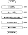
- FIG. It is a flowchart which shows the shutter opening / closing operation
- FIG. 1 is a diagram illustrating an internal configuration example of the banknote handling apparatus 10 according to the first exemplary embodiment.
- the banknote handling apparatus 10 is installed in a financial institution or the like.
- the banknote handling apparatus 10 is a staff operation type terminal that transacts banknotes based on operations by staff such as reception desk staff of financial institutions that are operators of the apparatus.
- the banknote handling apparatus 10 includes a deposit port 12, a first withdrawal port 14, a second withdrawal port 15, a bill recognition unit 20, a temporary storage unit 22, and a transport unit 24. , Banknote cassettes 30A to 30D, banknote cassette 35 with reject box, and display unit 40.
- the deposit port 12 is a slot into which a staff member inserts banknotes.
- the deposit port 12 may be provided with a shutter (not shown) for opening and closing the opening.
- the deposit port 12 has a separating function for separating and feeding out banknotes inserted in a bundle one by one.
- the first withdrawal port 14 and the second withdrawal port 15 are discharge ports from which banknotes received by the staff are discharged (withdrawn).
- the first withdrawal port 14 and the second withdrawal port 15 have a stacking function for stacking the banknotes to be discharged.
- the 1st withdrawal port 14 and the 2nd withdrawal port 15 have the capacity
- two withdrawal openings are provided.
- the present invention is not limited to this. For example, there may be three or more withdrawal openings.
- the first withdrawal port 14 has a first withdrawal port shutter (hereinafter referred to as a first shutter) 16 that opens and closes the opening portion.
- a second outlet shutter hereinafter referred to as a second shutter 17 for opening and closing the opening.
- FIG. 2A and FIG. 2B are schematic diagrams illustrating configuration examples of the first shutter 16 and the second shutter 17.
- 2A shows a state where the first shutter 16 and the second shutter 17 are closed
- FIG. 2B shows a state where the first shutter 16 is opened.
- the first shutter 16 and the second shutter 17 move to close the first withdrawal port 14 and the second withdrawal port 15.
- the 1st shutter 16 is closed
- the 2nd shutter 17 is Closed.
- the planar first shutter 16 and the second shutter 17 are slid and opened, but the curved shutter may be rotated and opened.
- the banknote recognition unit 20 discriminates banknotes passing one by one.
- the traveling direction of the banknotes corresponds to both directions, and the banknote recognition unit 20 can distinguish between banknotes conveyed from the direction of the deposit port 12 and banknotes conveyed from the opposite direction.
- the banknote recognition unit 20 determines the denomination, authenticity (genuine / fake) of banknotes conveyed through the conveyance path, correctness (correction / non-conformity), and running state (normal / abnormal). ) And the like, and a normality judgment or a rejection judgment is performed on the passing banknote.
- a genuine note means one that has been differentiated from a banknote
- a counterfeit note means one that has not been differentiated from a banknote.
- a correct ticket is a banknote identified as a genuine note that is identified as suitable for deposit / withdrawal
- a non-performing note is a banknote identified as a genuine note that is not suitable for deposit / withdrawal. This is what has been identified.
- the rejection determination is performed based on factors such as counterfeit bills, damaged bills (stains, damages, outer shape anomalies, etc.), running abnormalities (skew bills, heavy runs, etc.).
- the reject banknote may include a banknote that cannot be handled as a withdrawal banknote (for example, a 2000 yen bill or a 5000 yen bill) or may include a foreign banknote.
- the temporary storage unit 22 has both functions of separating and accumulating banknotes.
- the temporary storage unit 22 temporarily accumulates the banknotes separated from the deposit port 12 and identified as normal by the banknote recognition unit 20 during the deposit transaction.
- the banknotes accumulated in the temporary storage unit 22 are paid out when a transaction is established, for example, when the account of the deposited banknote is confirmed, etc., and conveyed to the banknote cassettes 30A to 30D through the banknote recognition unit 20.
- the temporary storage unit 22 may be an accumulation type that sequentially stacks and accumulates banknotes, or may be a drum type that sequentially winds and stores banknotes.
- the transport unit 24 includes a transport path, a transport roller that transports banknotes, and a drive mechanism that drives the transport rollers, and transports banknotes one by one.
- the drive mechanism drives the transport roller by rotating a DC servo motor or a pulse motor, for example.
- the transport unit 24 is controlled by a control unit which will be described later, and transports banknotes to a target transport destination (for example, the first withdrawal port 14 or the second withdrawal port 15).
- the banknote cassettes 30A to 30D are banknote storage units that can store banknotes for each denomination and have both functions of stacking and separating banknotes.
- the banknote cassettes 30A to 30D may include a plurality of banknote cassettes for the same denomination.
- the bill cassettes 30A and 30C may be bill cassettes for 10,000 yen bills
- the bill cassettes 30B and 30D may be bill cassettes for thousand yen bills.
- the banknote cassettes 30A to 30D have a structure that can be attached to and detached from the banknote handling apparatus 10, and the banknote cassettes 30A to 30D can be loaded with banknotes by exchanging them individually.
- the banknote cassette 35 with a reject box (hereinafter also referred to as a banknote cassette 35) has a structure that can be attached to and detached from the banknote processing apparatus 10, and can be collected and replenished by individually replacing the banknote cassette 35. Moreover, the banknote cassette 35 is equipped with the banknote storage 36 on the upper side, and the rejection store
- the banknote storage 36 has a stacking function for stacking banknotes and a separating function for feeding one by one.
- the banknote storage 36 can collect banknotes separated from the banknote cassettes 30A to 30D at the time of cassette count collection and collect banknotes. Further, the banknote storage 36 can feed banknotes accumulated in the banknote storage 36 for replenishing the cassette count, and can replenish banknotes 30A to 30D with banknotes.
- the reject box 37 has only a stacking function for stacking banknotes.
- the reject warehouse 37 is a banknote storage unit for stacking banknotes (reject banknotes) that have been identified as abnormal (rejection determination) by the banknote recognition unit 20.
- Display unit 40 displays a menu screen and a processing result screen.
- the display unit 40 is realized by, for example, a CRT (Cathode Ray Tube) display device, a liquid crystal display (LCD) device, or an OLED (Organic Light Emitting Diode) device.
- CTR Cathode Ray Tube
- LCD liquid crystal display
- OLED Organic Light Emitting Diode
- the banknote handling apparatus 10 has an operation unit (not shown) that can be operated by a staff member.
- the banknote processing apparatus 10 performs a depositing process or a withdrawal process corresponding to a transaction of depositing or withdrawing by the staff operating the operation unit.
- the banknote processing apparatus 10 may process based on the operation of the staff in the reception terminal connected to the banknote processing apparatus 10 instead of an operation part.
- the banknote handling apparatus 10 performs, for example, deposit processing, withdrawal processing, replenishment processing, and collection processing as basic processing. Below, it demonstrates for every process, referring FIG.
- the deposit process is a process for accumulating the bills in the deposit port 12 in the bill processing apparatus 10.
- the banknote processing apparatus 10 performs, for example, a normal deposit process in which a deposited banknote is retracted to the temporary storage unit 22 and then accumulated from the temporary storage unit 22 into the banknote cassettes 30 ⁇ / b> A to 30 ⁇ / b> D and a received banknote to the temporary storage unit 22.
- a direct depositing process that directly accumulates in the banknote cassettes 30A to 30D without retreating is performed.
- the banknote handling apparatus 10 can select a normal deposit process or a direct deposit process depending on the setting.
- the normal deposit process will be described.
- banknotes inserted into the deposit port 12 are separated and fed one by one, and the fed banknotes are conveyed to the banknote recognition unit 20 by the conveyance unit 24.
- the banknote recognition unit 20 performs banknote discrimination, and banknotes whose discrimination result is normal are conveyed to the temporary storage unit 22 and accumulated. After that, when the deposit amount is fixed, the process proceeds to accumulation processing.
- the banknote (reject banknote) in which the discrimination result by the banknote recognition unit 20 is abnormal is accumulated in the first withdrawal port 14 or the second withdrawal port 15.
- the banknotes accumulated in the first withdrawal port 14 or the second withdrawal port 15 can be re-differentiated by the banknote recognition unit 20 by being reinserted into the deposit port 12 by the staff.
- the process of discriminating banknotes by the banknote recognition unit 20 and transporting the banknotes to the transport destination based on the discrimination result is also referred to as counting process.
- banknotes are separated one by one from the temporary storage unit 22, and the separated banknotes are conveyed to the banknote recognition unit 20.
- the banknotes for which the discrimination result by the banknote recognition unit 20 is normal are accumulated in the banknote cassettes 30A to 30D corresponding to the denominations.
- banknotes for which the discrimination result by the banknote recognition unit 20 is abnormal such as running abnormal banknotes such as a dirty banknote, a folded banknote, and a skew banknote, are accumulated in the reject box 37 of the banknote cassette 35.
- the process proceeds to the return process.
- banknotes are separated one by one from the temporary holding unit 22, and the separated banknotes are conveyed to the banknote recognition unit 20. And even if the discrimination result by the banknote recognition part 20 is normal / abnormal, all the banknotes are accumulated in the 1st withdrawal port 14 or the 2nd withdrawal port 15.
- the banknote inserted into the deposit port 12 is identified by the banknote recognition unit 20 in the same manner as the normal deposit process.
- the banknotes for which the discrimination result is normal are accumulated in the banknote cassettes 30A to 30D corresponding to the denominations.
- banknotes (reject banknotes) whose discrimination results are abnormal are accumulated in the first withdrawal port 14 or the second withdrawal port 15.
- the banknotes accumulated in the first withdrawal port 14 or the second withdrawal port 15 can be re-differentiated by the banknote recognition unit 20 by being reinserted into the deposit port 12 by the staff.
- the withdrawal process is a process for accumulating the banknotes in the banknote cassettes 30A to 30D at the first withdrawal port 14 or the second withdrawal port 15.
- banknotes are separated and fed out from the banknote cassettes 30A to 30D one by one according to the designated amount, and the fed banknotes are transported to the banknote recognition section 20 by the transport section 24.
- the banknote recognition unit 20 performs banknote discrimination, and banknotes whose discrimination result is normal are accumulated in the first withdrawal port 14 or the second withdrawal port 15. Specifically, for example, depending on the denomination and number of normal banknotes to be withdrawn, the money is selectively accumulated (collected) at the first withdrawal port 14 or the second withdrawal port 15.
- banknotes with an abnormal discrimination result that is, banknotes that cannot be paid to the customer, are accumulated in the reject box 37 of the banknote cassette 35.
- the replenishment process is a process for replenishing the banknote processing apparatus 10 with banknotes.
- the banknote handling apparatus 10 as a specific replenishment method, a deposit port replenishment, a cassette replacement replenishment, and a cassette count replenishment are possible. Hereinafter, each replenishment method will be described.
- Replenishment of the deposit port is the same as the operation in the deposit process described above.
- banknotes fed out from the deposit port 12 and having a normal discrimination result by the banknote recognition unit 20 are evacuated to the temporary storage unit 22 and then accumulated in the banknote cassettes 30A to 30D corresponding to the denominations.
- the banknote whose discrimination result is abnormal is accumulated in the first withdrawal port 14 or the second withdrawal port 15.
- the cassette replacement replenishment utilizes the fact that the bill cassettes 30A to 30D are detachable, and the bill cassette loaded with bills in advance is exchanged with any of the bill cassettes 30A to 30D that have already been installed. To replenish. In cassette replacement replenishment, the operator must manually register the denomination and number of replenished banknotes.
- banknotes are loaded in advance into the banknote storage 36 of the banknote cassette 35 and set in the banknote processing apparatus 10.
- the banknotes fed out from the banknote storage 36 and having a normal discrimination result by the banknote recognition unit 20 are accumulated in the banknote cassettes 30A to 30D corresponding to the denominations.
- banknotes whose discrimination results are abnormal are accumulated in the reject box 37.
- the counting process is executed by the banknote recognition unit 20 in the cassette count replenishment, it is not necessary for the operator to manually register the denomination and the number of the replenished banknotes.
- the collection process is a process for collecting banknotes in the banknote processing apparatus 10.
- the banknote processing apparatus 10 as a specific collection method, withdrawal port collection, cassette exchange collection, and cassette count collection are possible. Hereinafter, each collection method will be described.
- the withdrawal port collection is the same as the operation in the withdrawal process described above.
- banknotes fed out from the banknote cassettes 30 ⁇ / b> A to 30 ⁇ / b> D to be collected and whose discrimination result by the banknote recognition unit 20 is normal are accumulated in the first withdrawal port 14 or the second withdrawal port 15.
- banknotes whose discrimination results are abnormal are accumulated in the reject box 37.
- the staff can collect the banknotes determined to be normal from the first withdrawal port 14 or the second withdrawal port 15. .
- the staff can collect the banknote determined to be abnormal from the reject box 37.
- the cassette exchange collection is performed by removing a predetermined banknote cassette from the banknote processing apparatus 10 among the banknote cassettes 30A to 30D.
- the operator needs to extract the banknotes from the removed banknote cassettes 30A to 30D and manually count the denomination and the number of the collected banknotes.
- the banknotes fed out of the banknote cassettes to be collected out of the banknote cassettes 30A to 30D and whose discrimination result by the banknote recognition unit 20 is normal are accumulated in the banknote storage 36 of the banknote cassette 35.
- banknotes whose discrimination results are abnormal are accumulated in the reject box 37.
- the staff removes only the banknote cassette 35 from the banknote processing apparatus 10, whereby the banknote determined to be normal and the banknote determined to be abnormal can be collected. Further, in the cassette counting and collecting, since the counting process is executed by the bill recognition unit 20, it is not necessary for the operator to manually count the denomination and the number of the collected bills.
- the banknote processing apparatus 10 transports banknotes to the first withdrawal port 14 and the second withdrawal port 15 during counting processing in the withdrawal process, but efficiently handles the banknotes transported to the two withdrawal ports.
- the shutter opening / closing operation of the first shutter 16 and the second shutter 17 is controlled.
- the shutter opening / closing operation according to the comparative example will be described.
- FIG. 3 is a flowchart showing the shutter opening / closing operation during the counting process according to the comparative example.
- the flowchart of FIG. 3 starts when a factor for stopping the counting process during the counting process of the withdrawal banknotes (for example, when the conveyance of all the withdrawal banknotes to the withdrawal port is completed) is detected.
- the stop factor of the counting process is detected, the counting process is stopped (step S802).
- step S804 only one of the first shutter 16 and the second shutter 17 (here, the first shutter 16) is opened (step S804). Thereby, the staff can extract the banknotes accumulated in the first withdrawal port 14. Then, when the withdrawal of the banknote from the first withdrawal port 14 is detected (step S806), the first shutter 16 is closed (step S808). Thereafter, the second shutter 17 of the second withdrawal port 15 is opened (step S810). Thereby, the staff can extract the banknotes accumulated in the second withdrawal port 15.
- the banknote processing apparatus 10 according to the first exemplary embodiment, the details will be described later, but after the banknotes in the first withdrawal port 14 are extracted, the first shutter 16 in the first withdrawal port 14. And the operation of opening the second shutter 17 of the second withdrawal port 15 are performed together.
- the first shutter 16 in the first withdrawal port 14
- the second withdrawal after the banknote from the first withdrawal port 14 is removed.
- the time until the banknote 15 is removed can be shortened.
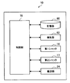
- FIG. 4 is a block diagram illustrating a functional configuration example of the banknote handling apparatus 10.
- the banknote handling apparatus 10 includes a control unit 70, a storage unit 80, and a detection unit 82.
- the control unit 70 controls the overall operation of the banknote handling apparatus 10. Specifically, the control unit 70 controls basic processes such as the above-described deposit process, withdrawal process, replenishment process, and recovery process. For example, the control unit 70 controls the conveyance of banknotes by the conveyance unit 24 and the opening / closing operations of the first shutter 16 and the second shutter 17.
- the 1st shutter 16 and the 2nd shutter 17 are as follows.
- the first shutter 16 corresponds to a first opening / closing member capable of opening / closing the first withdrawal port 14 by moving
- the second withdrawal port 15 can be opened / closed by moving the second shutter 17. It corresponds to a second opening / closing member.
- the control unit 70 When the banknote is transported to the first withdrawal port 14 and the second withdrawal port 15, the control unit 70, when one of the first withdrawal port 14 and the second withdrawal port 15 (here, When the withdrawal of the bill at the first withdrawal port 14 is detected, the operation of closing the first shutter 16 of the first withdrawal port 14 and the second of the other withdrawal port (second withdrawal port 15). 2 The operation of opening the shutter 17 is performed together. By performing both the operation of closing the first shutter 16 and the operation of opening the second shutter 17 in this way, the second shutter 17 is opened without waiting for the first shutter 16 to close. For this reason, it is possible to shorten the time from when the staff member pulls out the banknote in the first withdrawal port 14 to when the banknote in the second withdrawal port 15 is withdrawn.
- control unit 70 starts closing the first shutter 16 at the same time as the opening and closing timing of the first shutter 16 and the second shutter 17 when the withdrawal of the bill from the first withdrawal port 14 is detected. You may start opening 17. Thereby, the staff can extract the banknote of the 2nd withdrawal port 15 immediately after the 1st withdrawal port 14 is extracted. Therefore, it is possible to further shorten the time from when the banknote of the first withdrawal port 14 is extracted until the banknote of the second withdrawal port 15 is extracted.
- the opening / closing timing of the 1st shutter 16 and the 2nd shutter 17 when the extraction of the banknote of the 1st withdrawal port 14 is detected is not limited above.
- the control unit 70 may start opening the second shutter 17 in the middle of closing the first shutter 16 when the withdrawal of the banknote from the first withdrawal port 14 is detected. Even in such a case, the second shutter 17 is opened without waiting for the first shutter 16 to close. Therefore, the banknote in the second withdrawal port 15 after the staff member has taken out the bills in the first withdrawal port 14. Can be shortened. Further, the control unit 70 may start opening the second shutter 17 at the same time as closing the first shutter 16 when the withdrawal of the banknote from the first withdrawal port 14 is detected.
- the control unit 70 completes the conveyance of the banknotes, and then the first shutter 16 and the second shutter 17. Open one of the sides. Thereby, since the staff will withdraw banknotes of different denominations from the withdrawal port at different timings, it is possible to prevent the banknotes of different denominations that have been extracted from being mixed.
- the control part 70 when the banknote of the same denomination is conveyed by the 1st withdrawal port 14 and the 2nd withdrawal port 15, the control part 70 will complete
- the controller 70 opens the first shutter 16 and the second shutter 17 at the same time when the conveyance of banknotes is completed.
- the controller 70 opens the first shutter 16 and the second shutter 17 at the same time when the conveyance of banknotes is completed.
- the banknotes of the same denomination even if the banknotes of the first withdrawal port 14 and the second withdrawal port 15 are mixed, there is no fear that the staff will misidentify.
- the staff can perceive that the conveyance has been completed.
- the storage unit 80 stores a program or the like for operating the banknote processing apparatus 10. Moreover, the memory
- the detection unit 82 includes, for example, an optical sensor and detects various states. For example, the detection unit 82 detects the banknote stacking state (the number of stacked banknotes or whether or not banknotes have been extracted) at the first and second withdrawal ports 14 and 15. Moreover, the detection part 82 can detect the conveyance state of a banknote.
- the banknote stacking state the number of stacked banknotes or whether or not banknotes have been extracted
- control unit 70 and the storage unit 80 described above may be realized by a hardware configuration including a CPU (Central Processing Unit), a ROM (Read Only Memory), a RAM (Random Access Memory), and the like.
- the CPU has a calculation function and a control function, and controls the overall operation of the banknote handling apparatus 10 according to various programs.
- the ROM stores programs used by the CPU, calculation parameters, and the like.
- the RAM temporarily stores programs used in the execution of the CPU, parameters that change as appropriate during the execution, and the like.
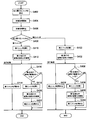
- FIG. 5 is a flowchart illustrating an example of a shutter opening / closing operation during the counting process according to the first exemplary embodiment.
- the flowchart in FIG. 5 is realized, for example, when the CPU of the control unit 70 executes a program stored in the ROM.
- the program to be executed may be stored in a recording medium such as a CD (Compact Disk), a DVD (Digital Versatile Disk), or a memory card, or may be downloaded from a server or the like via the Internet.
- the flowchart in FIG. 5 starts from the time when the withdrawal bill counting process is started.
- the control unit 70 separates the banknotes from the banknote cassettes 30A to 30D, conveys them to the banknote recognition unit 20, and based on the discrimination result of the banknote recognition unit 20, the banknotes are transferred to the first withdrawal port 14 or the second withdrawal port. 15 to transport.
- the control unit 70 conveys the first denomination banknote to the first withdrawal port 14 and conveys the second denomination banknote to the second withdrawal port 15.
- the control unit 70 stops the counting process when detecting a factor for stopping the counting process (for example, when the conveyance of all the dispensing banknotes to the dispensing port is completed) (step S102).
- the control unit 70 determines whether or not the banknotes conveyed to the first withdrawal port 14 and the second withdrawal port 15 are the same denomination (Step S104). If the denomination is different in Step S104 (No), the control unit 70 opens one of the first shutter 16 and the second shutter 17 (here, the first shutter 16) (Step S104). S106). Specifically, when the staff selects the first shutter 16 as the shutter that can be opened by the operation unit, only the first shutter 16 is opened. Thereby, the staff can extract the banknotes accumulated in the first withdrawal port 14.
- step S108 the control unit 70 processes the operations of the first shutter 16 and the second shutter 17 in parallel. That is, the control unit 70 closes the first shutter 16 (step S110). Moreover, the control part 70 determines whether the banknote is accumulate
- the control unit 70 starts opening the second shutter 17 at the same time as the first shutter 16 starts to close. Thereby, the staff can extract the banknote of the second denomination of the second withdrawal port 15 immediately after the banknote of the first denomination of the first withdrawal port 14 is extracted. Then, if it detects that the banknote of the 2nd withdrawal port 15 was extracted (step S116), the control part 70 will close the 2nd shutter 17 (step S118).
- the second shutter 17 starts to open simultaneously with the first shutter 16 starting to close.
- the present invention is not limited to this, and the second shutter 17 may start to open while the first shutter 16 is closing. Alternatively, the second shutter 17 may begin to open simultaneously with the first shutter 16 being closed.
- the control unit 70 operates the first shutter 16 and the second shutter 17. Are processed in parallel. That is, the control unit 70 determines whether or not banknotes are accumulated in the first withdrawal port 14 and the second withdrawal port 15 (steps S130 and S138), and the first withdrawal port 14 and the second withdrawal port 15 are determined.
- the first shutter 16 and the second shutter 17 are opened simultaneously (steps S132 and S140).
- step S134 when the control unit 70 detects that the banknote of the first withdrawal port 14 has been extracted (step S134), the control unit 70 closes the first shutter 16 (step S136). Moreover, if the control part 70 detects that the banknote of the 2nd withdrawal port 15 was extracted (step S142), the 2nd shutter 17 will be closed (step S144).
- the shutter opening / closing operations of the first shutter 16 and the second shutter 17 during counting processing in the dispensing process have been described, but the present invention is not limited to this.
- the above-described shutter opening / closing operation can be applied.
- the second shutter 17 is opened without waiting for the first shutter 16 to close. For this reason, since it is possible to shorten the time from when the staff withdraws the banknotes at the first withdrawal port 14 to when the banknotes at the second withdrawal port 15 are withdrawn, it is conveyed to the first withdrawal port 14 and the second withdrawal port 15. It is possible to efficiently extract the bills that have been made.
- Second Exemplary Embodiment> when the withdrawal of the banknote from the first withdrawal port 14 is detected, the first shutter 16 is closed and the second shutter 17 is opened. In the second exemplary embodiment, The second shutter 17 is opened regardless of the open / close state of the first shutter 16.
- the control unit 70 selects one withdrawal port (here, the first withdrawal port 14 and the second withdrawal port 15). Then, when the withdrawal of the bill at the first withdrawal port 14 is detected, an operation of opening the second shutter 17 of the other withdrawal port (second withdrawal port 15) is performed. Accordingly, the second shutter 17 is opened after the banknote is extracted from the first withdrawal port 14 regardless of the open / close state of the first shutter 16 of the first withdrawal port 14. For this reason, it is possible to shorten the time from when the staff member pulls out the banknote in the first withdrawal port 14 to when the banknote in the second withdrawal port 15 is withdrawn.
- control unit 70 opens the second shutter 17 in a state where the first shutter 16 is opened when the withdrawal of the banknote from the first withdrawal port 14 is detected.
- the 2nd shutter 17 will open immediately after extraction of the banknote of the 1st withdrawal port 14, and until a staff extracts the banknote of the 2nd withdrawal port 15 after extracting the banknote of the 1st withdrawal port 14. This time can be further shortened.
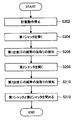
- FIG. 6 is a flowchart illustrating an example of a shutter opening / closing operation during the counting process according to the second exemplary embodiment.
- step S202 banknotes are accumulated in the first withdrawal port 14 and the second withdrawal port 15.
- the control unit 70 opens one of the first shutter 16 and the second shutter 17 (here, the first shutter 16) (step S204). Thereby, the staff can withdraw the banknotes of the first denomination accumulated in the first withdrawal port 14. Then, when it is detected that the banknote has been extracted from the first withdrawal port 14 (step S206), the control unit 70 opens the second shutter 17 without closing the first shutter 16 (step S208). Thereby, the staff can extract the banknotes of the second denomination accumulated in the second withdrawal port 15.
- control unit 70 detects that the banknote of the second withdrawal port 15 has been extracted (step S210)
- the control unit 70 closes the first shutter 16 and the second shutter 17 (step S212).
- the control unit 70 may close the first shutter 16 and the second shutter 17 simultaneously, or may close one of the shutters first and then close the other shutter.
- the staff member can make the first shutter 16.
- the banknotes in the second withdrawal port 15 can be extracted without waiting for the closing.
- the denominations of the bills conveyed to the first withdrawal port 14 and the second withdrawal port 15 are different from each other.
- the present invention is not limited to this, and the first withdrawal port 14 and the second withdrawal port. It is good also as the banknote of the same denomination being conveyed to the opening
- the withdrawal port here, the first withdrawal port
- the first shutter 16 is opened first, and the banknotes are continuously conveyed to another withdrawal port (second withdrawal port 15). Thereafter, when the conveyance of the banknote to the second withdrawal port 15 is completed, the second shutter 17 is opened.
- the staff can immediately extract the banknote of the first withdrawal port 14 for which the conveyance of the banknote has been completed.
- the second shutter 17 opens immediately if the banknotes are removed from the first withdrawal port 14. Fifteen bills can be extracted immediately.
- FIG. 7 is a flowchart illustrating an example of a shutter opening / closing operation during the counting process according to the third exemplary embodiment.
- the flowchart in FIG. 7 also starts when the withdrawal bill counting process is started. And the control part 70 of the payment banknote of the 1st denomination to one withdrawal opening (here 1st withdrawal opening 14) of the 1st withdrawal opening 14 and the 2nd withdrawal opening 15 is carried out. The conveyance is started (step S302).
- the control unit 70 ends the conveyance of the banknote to the first withdrawal port 14 (step S304). Then, the control unit 70 processes the operations of the first shutter 16 and the second shutter 17 in parallel. That is, the control unit 70 opens the first shutter 16 (step S306). Thereby, the staff can extract the banknote of the 1st denomination of the 1st withdrawal port 14. Then, if it detects that the banknote of the 1st payment port 14 was extracted (step S308), the control part 70 will close the 1st shutter 16 (step S310).
- the control unit 70 determines whether or not banknotes (banknotes of the second denomination) to be transported remain in the second withdrawal port 15 (step S312).
- step S312 conveyance of the banknote to the 2nd withdrawal port 15 is started (step S314).
- step S 316 the control unit 70 ends the transport of the banknote to the second withdrawal port 15 (step S 316) and opens the second shutter 17. (Step S318).
- the staff can extract the banknote of the second denomination of the second withdrawal port 15.
- the control part 70 will close the 2nd shutter 17 (step S322).
- the fourth exemplary embodiment it is possible to set a shutter to be opened first of the first shutter 16 and the second shutter 17 in advance. And after conveyance of the banknote to the 1st withdrawal port 14 and the 2nd withdrawal port 15 is completed (for example, stop of counting processing), the set shutter opens first. Thereby, the staff can extract the banknote of the 1st withdrawal port 14 and the 2nd withdrawal port 15 in the order set up beforehand.
- FIG. 8 is a flowchart illustrating an example of a shutter opening / closing operation during the counting process according to the fourth exemplary embodiment.
- the flowchart in FIG. 8 is started when the staff sets a shutter to be opened first of the first shutter 16 and the second shutter 17 (step S402). Thereby, the staff can take out first the banknotes accumulated in the desired withdrawal port of the first withdrawal port 14 and the second withdrawal port 15. And the control part 70 starts a count process (step S404).
- control unit 70 stops the counting process when detecting a factor for stopping the counting process (for example, when the conveyance of all the withdrawal banknotes to the withdrawal port is completed) (step S406).
- control unit 70 determines the shutter set by the staff in step S402 (step S408).
- step S410 the control unit 70 opens the first shutter 16 (step S410). Thereby, the staff can extract the banknotes accumulated in the first withdrawal port 14 first. Thereafter, when it is detected that the banknotes from the first withdrawal port 14 have been extracted (step S412), the control unit 70 processes the operations of the first shutter 16 and the second shutter 17 in parallel.
- step S416 when banknotes are accumulated in the second withdrawal port 15 (step S416: Yes), the control unit 70 starts opening the second shutter 17 at the same time as starting to close the first shutter 16 (step S416). S414, S418). Thereby, the staff can extract the banknote of the second denomination of the second withdrawal port 15 immediately after the banknote of the first denomination of the first withdrawal port 14 is extracted. Then, if it detects that the banknote of the 2nd withdrawal port 15 was extracted (step S420), the control part 70 will close the 2nd shutter 17 (step S422).
- step S408 When the shutter that is opened first in step S408 is the second shutter 17, the control unit 70 opens the second shutter 17 (step S430). Thereby, the staff can extract the banknotes accumulated in the second withdrawal port 15 first. Thereafter, when it is detected that the banknote of the second withdrawal port 15 has been extracted (step S432), the control unit 70 processes the operations of the first shutter 16 and the second shutter 17 in parallel.
- step S436 when banknotes are accumulated in the first withdrawal port 14 (step S436: Yes), the control unit 70 starts opening the first shutter 16 at the same time as starting to close the second shutter 17 (step S436). S434, S438). As a result, the staff can extract the first denomination banknote from the first withdrawal port 14 immediately after the second denomination banknote from the second withdrawal port 15 is extracted. Then, if it detects that the banknote of the 1st payment port 14 was extracted (step S440), the control part 70 will close the 1st shutter 16 (step S442).
- each step in the processing of the banknote processing apparatus 10 described above does not necessarily have to be processed in time series in the order described as a flowchart.
- each step in the processing of the banknote processing apparatus 10 may be processed in an order different from the order described as the flowchart, or may be processed in parallel.
- the banknote handling apparatus 10 is described as being applied to a staff operation type terminal, but the present invention is not limited to this.
- the present invention may be applied to a cash processing unit of an automatic transaction apparatus represented by an ATM (Automated teller machine) that is a customer operation type terminal that recirculates (recycles) banknotes.
- ATM Automated teller machine
- Automatic transaction apparatuses are installed in various places such as banks, station premises, and convenience stores. The customer can perform transactions such as deposit, withdrawal and balance inquiry by performing various operations on the display screen displayed on the automatic transaction apparatus.
Landscapes
- Physics & Mathematics (AREA)
- General Physics & Mathematics (AREA)
- Financial Or Insurance-Related Operations Such As Payment And Settlement (AREA)
Description
本発明は、紙幣処理装置、及び紙幣処理方法に関する。
金融機関の営業店カウンタ等に、窓口用現金処理機に代表される現金処理装置が設置されている。現金処理装置は、紙幣や硬貨の入金取引や出金取引等に利用される。職員は、例えば、現金処理装置の操作部、又は現金処理装置に接続された受付端末から操作を行うことにより、入金取引や出金取引を行うことができる。
下記の特開2001-93022号公報には、紙幣入金口に投入された紙幣を一時保留部に一時保留した後にスタッカに収納する入金処理と、スタッカに収納された紙幣を分離して紙幣出金口に搬送する出金処理とを行う現金処理装置が開示されている。
上記の特開2001-93022号公報の紙幣出金口は、1つであるため、多量の紙幣をまとめて搬送することが困難である。そこで、紙幣出金口を二つ設ける方策が検討されている。
ところで、紙幣出金口には、通常、開閉可能なシャッタが設けられており、紙幣の搬送中はシャッタが閉じている。そして、紙幣出金口の紙幣を抜き取るためには、シャッタを開ける必要がある。このため、紙幣出金口を二つ設けた場合には、各出金口にシャッタを設けることになる。しかし、2つの出金口に紙幣を搬送した場合に、2つの出金口の紙幣を効率的に抜き取るためのシャッタの開閉動作については、検討されていなかった。
本発明は、2つの出金口に搬送された紙幣を効率的に抜き取ることが可能な、新規かつ改良された紙幣処理装置を提供する。
本発明の第1の態様は、紙幣処理装置であって、紙幣が搬送される第1出金口及び第2出金口と、移動することにより前記第1出金口を開閉可能な第1開閉部材と、移動することにより前記第2出金口を開閉可能な第2開閉部材と、前記第1出金口又は前記第2出金口の紙幣の抜き取りを検知する検知部と、前記第1出金口及び前記第2出金口に紙幣が搬送された際に前記第1出金口の紙幣の抜き取りが検知されると、前記第1開閉部材を閉じる動作、及び前記第2開閉部材を開ける動作を共に行う制御部と、を備える。
本発明の第1の態様によれば、制御部は、第1出金口及び第2出金口に紙幣が搬送された際に第1出金口の紙幣の抜き取りが検知されると、第1開閉部材を閉じる動作、及び第2開閉部材を開ける動作を共に行う。これにより、第1開閉部材が閉じるのを待たずに、第2開閉部材は、開くことになる。このため、本発明の第1の態様は、職員が第1出金口の紙幣を抜き取ってから第2出金口の紙幣を抜き取るまでの時間を短縮できるので、第1出金口及び第2出金口に搬送された紙幣を効率的に抜き取ることができる。
また、本発明の第2の態様は、上記態様において、前記制御部は、前記第1出金口の紙幣の抜き取りが検知されると、前記第1開閉部材を閉め始めると同時に、前記第2開閉部材を開け始めることとしても良い。
また、本発明の第3の態様は、上記態様において、前記制御部は、前記第1出金口の紙幣の抜き取りが検知されると、前記第1開閉部材を閉める途中で、前記2開閉部材を開け始めることとしても良い。
また、本発明の第4の態様は、上記態様において、前記制御部は、前記第1出金口の紙幣の抜き取りが検知されると、前記第1開閉部材を閉め終わると同時に、前記第2開閉部材を開け始めることとしても良い。
また、本発明の第5の態様は、上記態様において、前記制御部は、前記第1出金口と前記第2出金口に異なる金種の紙幣が搬送された場合には、前記紙幣の搬送が完了すると、前記第1開閉部材及び前記第2開閉部材の一方を開けることとしても良い。
また、本発明の第6の態様は、上記態様において、前記制御部は、前記第1出金口と前記第2出金口に同じ金種の紙幣が搬送された場合には、前記紙幣の搬送が完了すると、前記第1開閉部材と前記第2開閉部材を共に開けることとしても良い。
また、本発明の第7の態様は、上記態様において、前記制御部は、前記紙幣の搬送が完了すると、前記第1開閉部材と前記第2開閉部材を同時に開けることとしても良い。
また、本発明の第8の態様は、紙幣処理装置であって、紙幣が搬送される第1出金口及び第2出金口と、移動することにより前記第1出金口を開閉可能な第1開閉部材と、移動することにより前記第2出金口を開閉可能な第2開閉部材と、前記第1出金口又は前記第2出金口の紙幣の抜き取りを検知する検知部と、前記第1出金口及び前記第2出金口に紙幣が搬送された際に前記第1出金口の紙幣の抜き取りが検知されると、前記第2開閉部材を開ける動作を行う制御部と、を備える。
また、本発明の第9の態様は、上記態様において、前記制御部は、前記第1出金口の紙幣の抜き取りが検知されると、前記第1開閉部材を開いた状態で、前記第2開閉部材を開けることとしても良い。
また、本発明の第10の態様は、1出金口及び第2出金口への紙幣の搬送と、前記第1出金口を開閉可能な第1開閉部材及び前記第2出金口を開閉可能な第2開閉部材の開閉動作と、を制御する紙幣処理方法であって、前記第1出金口及び前記第2出金口に紙幣を搬送し、前記紙幣の搬送後に前記第1出金口又は前記第2出金口の紙幣の抜き取りを検知部が検知し、前記第1出金口の紙幣の抜き取りが検知されると、前記第1開閉部材を閉じる動作、及び前記第2開閉部材を開ける動作を共に行う、ことを有する。
以上説明したように本発明によれば、2つの出金口に搬送された紙幣を効率的に抜き取ることが可能となる。
以下に添付図面を参照しながら、本発明の好適な実施の形態について詳細に説明する。なお、本明細書及び図面において、実質的に同一の機能構成を有する構成要素については、同一の符号を付することにより重複説明を省略する。
<1.第1の例示的実施形態>
(1-1.紙幣処理装置の内部構成例)
図1を参照しながら、第1の例示的実施形態に係る紙幣処理装置10の内部構成例について説明する。
(1-1.紙幣処理装置の内部構成例)
図1を参照しながら、第1の例示的実施形態に係る紙幣処理装置10の内部構成例について説明する。
図1は、第1の例示的実施形態に係る紙幣処理装置10の内部構成例を示す図である。紙幣処理装置10は、金融機関の営業店等に設置されている。紙幣処置装置10は、装置の操作者である金融機関の受付窓口員等の職員による操作に基づいて、紙幣の取引を行う職員操作型端末である。
紙幣処理装置10は、図1に示すように、入金口12と、第1出金口14と、第2出金口15と、紙幣認識部20と、一時保留部22と、搬送部24と、紙幣カセット30A~30Dと、リジェクト庫付き紙幣カセット35と、表示部40とを有する。
入金口12は、職員が紙幣を投入する投入口である。入金口12には、開口部を開閉するシャッタ(不図示)を設けるようにしてもよい。また、入金口12は、束で投入された紙幣を一枚ずつ分離して繰り出す分離機能を有する。
第1出金口14及び第2出金口15は、職員が受け取る紙幣が排出(出金)される排出口である。第1出金口14及び第2出金口15は、排出する紙幣を集積する集積機能を有する。第1出金口14及び第2出金口15は、一例として、紙幣を100枚(最大集積枚数)集積できる容量を有する。図1に示す例では、出金口が2つ設けられているが、これに限定されず、例えば出金口が3つ以上であってもよい。なお、図2A、図2Bに示すように、第1出金口14には開口部を開閉する第1出金口シャッタ(以下、第1シャッタと呼ぶ)16が、第2出金口15には開口部を開閉する第2出金口シャッタ(以下、第2シャッタと呼ぶ)17が、それぞれ設けられている。
図2A、及び図2Bは、第1シャッタ16及び第2シャッタ17の構成例を示す模式図である。図2Aには、第1シャッタ16及び第2シャッタ17が閉じた状態が示され、図2Bには、第1シャッタ16が開いた状態が示されている。第1シャッタ16及び第2シャッタ17は、移動することにより第1出金口14と第2出金口15を閉じる。なお、第1出金口14に紙幣が搬送されている際には、第1シャッタ16は閉じており、第2出金口15に紙幣が搬送されている際には、第2シャッタ17は閉じている。なお、図2A、及び図2Bでは、平面状の第1シャッタ16及び第2シャッタ17をスライドさせて開閉させているが、曲面状のシャッタを回動させて開閉されても良い。
紙幣認識部20は、1枚ずつ通過していく紙幣の鑑別を行う。紙幣の進行方向は双方向に対応しており、紙幣認識部20は、入金口12側の方向から搬送される紙幣、およびその逆方向から搬送される紙幣の鑑別を行うことができる。具体的には、紙幣認識部20は、搬送路を通って搬送された紙幣の金種、真偽(真券/偽券)、正損(正券/損券)および走行状態(正常/異常)などを鑑別し、通過する紙幣に対して、正常判定またはリジェクト判定を行う。
ここで、本明細書において真券とは紙幣と鑑別されたものをいい、偽券とは紙幣と鑑別されなかったものをいう。また、正券とは真券と鑑別された紙幣のうち入金/出金に適すると鑑別されたものをいい、損券とは真券と鑑別された紙幣のうち入金/出金に適さないと鑑別されたものをいう。また、リジェクト判定は、偽券、損券(汚損、損壊、外形異常等)、走行異常(スキュー紙幣、重走等)といった要因に基づいて行われる。また、リジェクト紙幣には、出金紙幣として取り扱えない紙幣(例えば二千円札や五千円札)を含んでもよいし、外国紙幣を含んでもよい。
一時保留部22は、紙幣の分離と集積の両方の機能を有する。例えば、一時保留部22は、入金取引時に入金口12から分離されて紙幣認識部20により正常と鑑別された紙幣を一時的に集積する。一時保留部22に集積された紙幣は、入金した紙幣の口座計上などが確定したなど、取引が成立した場合に繰り出され、紙幣認識部20を経て紙幣カセット30A~30Dなどに搬送される。なお、一時保留部22は、紙幣を順次重ねて集積する集積式であってもよいし、紙幣を順次巻いて収納するドラム式であってもよい。
搬送部24は、搬送路、紙幣を搬送する搬送ローラ、および搬送ローラを駆動する駆動機構を含み、紙幣を一枚ずつ搬送する。駆動機構は、例えばDCサーボモータまたはパルスモータなどが回転することにより、搬送ローラを駆動する。搬送部24は、後述する制御部により制御され、紙幣を目的の搬送先(例えば、第1出金口14又は第2出金口15)に搬送する。
紙幣カセット30A~30Dは、紙幣を金種毎に収納可能な紙幣収納部であって、紙幣の集積および分離の両方の機能を有する。また、紙幣カセット30A~30Dは、同一金種のための複数の紙幣カセットを含んでもよい。例えば、紙幣カセット30Aおよび30Cが一万円札用の紙幣カセットであり、紙幣カセット30Bおよび30Dが千円札用の紙幣カセットであってもよい。また、紙幣カセット30A~30Dは、紙幣処理装置10に対して着脱可能な構造になっており、個別に交換することで紙幣カセット30A~30Dに紙幣を装填することも可能である。
リジェクト庫付き紙幣カセット35(以下、紙幣カセット35とも称す)は、紙幣処理装置10に対して着脱可能な構造になっており、個別に交換することで、紙幣の回収および補充が可能である。また、紙幣カセット35は、上側に紙幣収納庫36、下側(底部)にリジェクト庫37を備える。
紙幣収納庫36は、紙幣を集積する集積機能および1枚ずつ繰り出す分離機能を有する。また、紙幣収納庫36は、カセット計数回収時に各紙幣カセット30A~30Dから分離された紙幣を集積し、紙幣を回収することができる。また、紙幣収納庫36は、カセット計数補充に、紙幣収納庫36内に集積している紙幣を繰り出し、紙幣カセット30A~30Dに紙幣を補充することができる。
リジェクト庫37は、紙幣を集積する集積機能のみ有する。リジェクト庫37は、紙幣認識部20によって異常と鑑別(リジェクト判定)された紙幣(リジェクト紙幣)を集積するための紙幣収納部である。
表示部40は、メニュー画面や処理結果画面を表示する。表示部40は、例えば、CRT(Cathode Ray Tube)ディスプレイ装置、液晶ディスプレイ(LCD)装置、OLED(Organic Light Emitting Diode)装置により実現される。
また、紙幣処理装置10は、職員が操作可能な操作部(不図示)を有する。紙幣処理装置10は、職員が操作部を操作することにより、入金や出金の取引に対応する入金処理や出金処理等を行う。なお、紙幣処理装置10は、操作部の代わりに、紙幣処理装置10に接続された受付端末における職員の操作に基づいて、処理を行なっても良い。
(1-2.紙幣処理装置の基本処理)
紙幣処置装置10は、基本処理として、例えば入金処理、出金処理、補充処理、回収処理を行う。以下では、図1を参照しながら処理毎に説明する。
紙幣処置装置10は、基本処理として、例えば入金処理、出金処理、補充処理、回収処理を行う。以下では、図1を参照しながら処理毎に説明する。
(入金処理)
入金処理は、入金口12の紙幣を紙幣処理装置10の内部に集積する処理である。紙幣処理装置10は、入金処理として、例えば、入金紙幣を一時保留部22へ退避させた後に一時保留部22から紙幣カセット30A~30Dに集積する通常入金処理と、入金紙幣を一時保留部22へ退避させないで直接紙幣カセット30A~30Dに集積するダイレクト入金処理とを行う。なお、紙幣処理装置10は、設定により通常入金処理又はダイレクト入金処理を選択することができる。
入金処理は、入金口12の紙幣を紙幣処理装置10の内部に集積する処理である。紙幣処理装置10は、入金処理として、例えば、入金紙幣を一時保留部22へ退避させた後に一時保留部22から紙幣カセット30A~30Dに集積する通常入金処理と、入金紙幣を一時保留部22へ退避させないで直接紙幣カセット30A~30Dに集積するダイレクト入金処理とを行う。なお、紙幣処理装置10は、設定により通常入金処理又はダイレクト入金処理を選択することができる。
まず、通常入金処理について説明する。通常入金処理においては、まず、入金口12に投入された紙幣が一枚ずつ分離して繰り出され、繰り出された紙幣は、搬送部24により紙幣認識部20に搬送される。次に、紙幣認識部20が紙幣の鑑別を行い、鑑別結果が正常であった紙幣は、一時保留部22へ搬送されて集積される。その後、入金金額が確定すると、集積処理に移行する。
一方で、紙幣認識部20による鑑別結果が異常であった紙幣(リジェクト紙幣)は、第1出金口14又は第2出金口15に集積される。第1出金口14又は第2出金口15に集積された紙幣は、職員により入金口12に再投入されることで、紙幣認識部20による再鑑別が可能である。なお、以下において、紙幣認識部20により紙幣を鑑別し、鑑別結果に基づき搬送先に紙幣を搬送する処理を計数処理とも呼ぶ。
集積処理においては、まず、一時保留部22から紙幣が1枚ずつ分離され、分離された紙幣が紙幣認識部20に搬送される。次に、紙幣認識部20による鑑別結果が正常であった紙幣は、金種に対応する紙幣カセット30A~30Dに集積される。一方で、汚損券、折れ紙幣、スキュー紙幣などの走行異常紙幣のように、紙幣認識部20による鑑別結果が異常であった紙幣は、紙幣カセット35のリジェクト庫37に集積される。
一方で、入金金額の確定前に入金紙幣の返却(キャンセル)が指示されると、返却処理に移行する。返却処理においては、まず、一時保留部22から紙幣が1枚ずつ分離され、分離された紙幣が紙幣認識部20に搬送される。そして、紙幣認識部20による鑑別結果が正常/異常いずれであっても、全ての紙幣を第1出金口14、又は第2出金口15へ集積する。
次に、ダイレクト入金処理について説明する。入金口12に投入された紙幣は、通常入金処理と同様に、紙幣認識部20により鑑別される。そして、鑑別結果が正常であった紙幣は、金種に対応する紙幣カセット30A~30Dに集積される。一方で、鑑別結果が異常であった紙幣(リジェクト紙幣)は、第1出金口14又は第2出金口15に集積される。第1出金口14又は第2出金口15に集積された紙幣は、職員により入金口12に再投入されることで、紙幣認識部20による再鑑別が可能である。
(出金処理)
出金処理は、紙幣カセット30A~30Dの紙幣を第1出金口14又は第2出金口15に集積する処理である。
出金処理は、紙幣カセット30A~30Dの紙幣を第1出金口14又は第2出金口15に集積する処理である。
出金処理においては、まず、指定された金額に応じて紙幣カセット30A~30Dから紙幣が1枚ずつ分離して繰り出され、繰り出された紙幣は、搬送部24により紙幣認識部20に搬送される。次に、紙幣認識部20が紙幣の鑑別を行い、鑑別結果が正常であった紙幣は、第1出金口14又は第2出金口15に集積される。具体的には、例えば出金する正常紙幣の金種や枚数に応じて、第1出金口14又は第2出金口15に選択的に集積(集金)される。一方で、鑑別結果が異常であった紙幣、すなわち、顧客に支払いできない紙幣は、紙幣カセット35のリジェクト庫37に集積される。
(補充処理)
補充処理は、紙幣処理装置10に紙幣を補充する処理である。紙幣処理装置10においては、具体的な補充方法として、入金口補充、カセット交換補充、およびカセット計数補充が可能である。以下、各補充方法について説明する。
補充処理は、紙幣処理装置10に紙幣を補充する処理である。紙幣処理装置10においては、具体的な補充方法として、入金口補充、カセット交換補充、およびカセット計数補充が可能である。以下、各補充方法について説明する。
入金口補充は、上述した入金処理における動作と同様である。例えば、入金口12から繰り出され、紙幣認識部20による鑑別結果が正常であった紙幣は、一時保留部22に退避された後、金種に対応する紙幣カセット30A~30Dに集積される。一方で、鑑別結果が異常であった紙幣は、第1出金口14又は第2出金口15に集積される。
カセット交換補充は、紙幣カセット30A~30Dが着脱可能であることを利用するものであり、予め紙幣を装填した紙幣カセットを、既に装着された紙幣カセット30A~30Dのいずれかと交換することで、紙幣を補充する。なお、カセット交換補充では、補充した紙幣の金種と枚数をオペレータがマニュアルで登録する必要がある。
カセット計数補充においては、まず、紙幣カセット35の紙幣収納庫36に予め紙幣を装填し、紙幣処理装置10にセットする。次に、紙幣収納庫36から繰り出され、紙幣認識部20による鑑別結果が正常であった紙幣は、金種に対応する紙幣カセット30A~30Dに集積される。一方で、鑑別結果が異常であった紙幣は、リジェクト庫37に集積される。なお、カセット計数補充では、紙幣認識部20により計数処理が実行されるので、補充した紙幣の金種および枚数をオペレータがマニュアルで登録する必要はない。
(回収処理)
回収処理は、紙幣処理装置10内の紙幣を回収する処理である。紙幣処理装置10においては、具体的な回収方法として、出金口回収、カセット交換回収、およびカセット計数回収が可能である。以下、各回収方法について説明する。
回収処理は、紙幣処理装置10内の紙幣を回収する処理である。紙幣処理装置10においては、具体的な回収方法として、出金口回収、カセット交換回収、およびカセット計数回収が可能である。以下、各回収方法について説明する。
出金口回収は、上述した出金処理における動作と同様である。例えば、回収対象の紙幣カセット30A~30Dから繰り出され、紙幣認識部20による鑑別結果が正常であった紙幣は、第1出金口14又は第2出金口15に集積される。一方で、鑑別結果が異常であった紙幣は、リジェクト庫37に集積される。そして、回収対象の紙幣カセット30A~30Dに集積された全紙幣に対して行い、職員は、第1出金口14又は第2出金口15から、正常判定された紙幣を回収することができる。また、職員は、リジェクト庫37から異常判定された紙幣を回収することができる。
カセット交換回収は、紙幣カセット30A~30Dのうちの所定の紙幣カセットを紙幣処理装置10から取り外すことで、紙幣の回収を行う。なお、カセット交換回収では、オペレータが、取り外した紙幣カセット30A~30Dから紙幣を抜き取り、回収した紙幣の金種と枚数をマニュアルで数える必要がある。
カセット計数回収においては、紙幣カセット30A~30Dのうち回収対象の紙幣カセットから繰り出され、紙幣認識部20による鑑別結果が正常であった紙幣は、紙幣カセット35の紙幣収納庫36に集積される。一方で、鑑別結果が異常であった紙幣は、リジェクト庫37に集積される。その後、職員が紙幣カセット35のみを紙幣処理装置10から取り外すことで、正常判定された紙幣および異常判定された紙幣を回収することができる。また、カセット計数回収では、紙幣認識部20により計数処理が実行されるので、回収した紙幣の金種および枚数をオペレータがマニュアルで数える必要はない。
(1-3.計数処理時のシャッタ開閉動作について)
紙幣処理装置10は、出金処理における計数処理等の際に第1出金口14及び第2出金口15に紙幣を搬送するが、2つの出金口に搬送された紙幣を効率的に抜き取るために、第1シャッタ16と第2シャッタ17のシャッタ開閉動作を制御している。ここでは、本例示的実施形態に係るシャッタ開閉動作を説明する前に、比較例に係るシャッタ開閉動作について説明する。
紙幣処理装置10は、出金処理における計数処理等の際に第1出金口14及び第2出金口15に紙幣を搬送するが、2つの出金口に搬送された紙幣を効率的に抜き取るために、第1シャッタ16と第2シャッタ17のシャッタ開閉動作を制御している。ここでは、本例示的実施形態に係るシャッタ開閉動作を説明する前に、比較例に係るシャッタ開閉動作について説明する。
図3を参照しながら、比較例に係る計数処理時の第1シャッタ16及び第2シャッタ17の開閉動作について説明する。図3は、比較例に係る計数処理時におけるシャッタ開閉動作を示すフローチャートである。
図3のフローチャートは、出金紙幣の計数処理中に計数処理を停止する要因(例えば、全ての出金紙幣の出金口への搬送が完了した場合)を検知したところから開始される。計数処理の停止要因を検知すると、計数処理が停止する(ステップS802)。
次に、第1シャッタ16と第2シャッタ17の一方(ここでは、第1シャッタ16とする)のみを開ける(ステップS804)。これにより、職員は、第1出金口14に集積された紙幣を抜き取ることができる。そして、第1出金口14からの紙幣の抜き取りが検知されると(ステップS806)、第1シャッタ16が閉まる(ステップS808)。その後、第2出金口15の第2シャッタ17が開く(ステップS810)。これにより、職員は、第2出金口15に集積された紙幣を抜き取ることができる。
比較例の場合には、2つの出金口14、15の紙幣を順番に抜き取るため、第2出金口15の紙幣を抜き取るためには、第1シャッタ16が閉まるまで待つ必要がある。このため、第2出金口15から紙幣を抜き取るのに時間を要する。
これに対して、第1の例示的実施形態に係る紙幣処理装置10では、詳細は後述するが、第1出金口14の紙幣を抜き取った後に、第1出金口14の第1シャッタ16を閉める動作と、第2出金口15の第2シャッタ17を開く動作とを共に行う。これにより、比較例とは異なり、第2出金口15の紙幣を抜き取るのに第1シャッタ16が閉まるのを待つ必要が無いので、第1出金口14の紙幣を抜き取ってから第2出金口15の紙幣を抜き取るまでの時間を短縮することができる。
(1-4.紙幣処理装置の機能構成例)
図4を参照しながら、紙幣処理装置10の機能構成例について説明する。図4は、紙幣処理装置10の機能構成例を示すブロック図である。図4に示すように、紙幣処理装置10は、制御部70と、記憶部80と、検知部82とを備える。
図4を参照しながら、紙幣処理装置10の機能構成例について説明する。図4は、紙幣処理装置10の機能構成例を示すブロック図である。図4に示すように、紙幣処理装置10は、制御部70と、記憶部80と、検知部82とを備える。
制御部70は、紙幣処理装置10の動作全般を制御する。具体的には、制御部70は、上述した入金処理、出金処理、補充処理、回収処理等の基本処理を制御する。例えば、制御部70は、搬送部24による紙幣の搬送と、第1シャッタ16及び第2シャッタ17の開閉動作とを制御する。
ところで、第1の例示的実施形態において、制御部70は、第1出金口14及び第2出金口15に紙幣を搬送する際に、第1シャッタ16及び第2シャッタ17を以下のように制御する。ここでは、第1シャッタ16が、移動することにより第1出金口14を開閉可能な第1開閉部材に該当し、第2シャッタ17が、移動することにより第2出金口15を開閉可能な第2開閉部材に該当するものとする。
制御部70は、第1出金口14及び第2出金口15に紙幣が搬送された際に、第1出金口14及び第2出金口15の一方の出金口(ここでは、第1出金口14とする)の紙幣の抜き取りが検知されると、第1出金口14の第1シャッタ16を閉じる動作、及び他方の出金口(第2出金口15)の第2シャッタ17を開ける動作を共に行う。このように第1シャッタ16を閉じる動作と第2シャッタ17を開ける動作を共に行うことで、第1シャッタ16が閉じるのを待たずに、第2シャッタ17が開くことになる。このため、職員が第1出金口14の紙幣を抜き取ってから第2出金口15の紙幣を抜き取るまでの時間を短縮できる。
また、制御部70は、第1出金口14の紙幣の抜き取りが検知された際の第1シャッタ16と第2シャッタ17の開閉タイミングとして、第1シャッタ16を閉め始めると同時に、第2シャッタ17を開け始めても良い。これにより、職員は、第1出金口14の抜き取り後に、直ぐに第2出金口15の紙幣を抜き取ることができる。従って、第1出金口14の紙幣を抜き取ってから第2出金口15の紙幣を抜き取るまでの時間を、より短縮できる。
なお、第1出金口14の紙幣の抜き取りが検知された際の第1シャッタ16と第2シャッタ17の開閉タイミングは、上記に限定されない。例えば、制御部70は、第1出金口14の紙幣の抜き取りが検知されると、第1シャッタ16を閉める途中で、第2シャッタ17を開け始めても良い。かかる場合にも、第1シャッタ16が閉じるのを待たずに、第2シャッタ17が開くことになるので、職員が第1出金口14の紙幣を抜き取ってから第2出金口15の紙幣を抜き取るまでの時間を短縮できる。また、制御部70は、第1出金口14の紙幣の抜き取りが検知されると、第1シャッタ16を閉め終わると同時に、第2シャッタ17を開け始めても良い。
また、制御部70は、第1出金口14と第2出金口15に異なる金種の紙幣が搬送された場合には、紙幣の搬送が完了すると、第1シャッタ16及び第2シャッタ17の一方を開ける。これにより、職員は異なる金種の紙幣を異なるタイミングで出金口から抜き取ることになるので、抜き取った異なる金種の紙幣が混在することを防止できる。
また、制御部70は、第1出金口14と第2出金口15に同じ金種の紙幣が搬送された場合には、紙幣の搬送が完了すると、第1シャッタ16と第2シャッタ17を共に開ける。例えば、制御部70は、紙幣の搬送が完了すると、第1シャッタ16と第2シャッタ17を同時に開ける。同じ金種の紙幣の場合には、第1出金口14と第2出金口15の紙幣を混ぜても職員等が誤認する恐れが無い。一方で、2つのシャッタを共に開けることで、搬送が完了したことを職員に知覚させることができる。
記憶部80は、紙幣処理装置10が動作するためのプログラム等を記憶する。また、記憶部80は、紙幣認識部20の鑑別結果を記憶しうる。
検知部82は、例えば光学センサ等を有し、様々な状態を検知する。例えば、検知部82は、第1出金口14や第2出金口15の紙幣の集積状態(集積枚数や、紙幣が抜き取られたか否か)を検知する。また、検知部82は、紙幣の搬送状態を検知しうる。
なお、上述した制御部70、および記憶部80の機能は、CPU(Central Processing Unit)、ROM(Read Only Memory)、およびRAM(Random Access Memory)等から成るハードウェア構成により実現してもよい。CPUは、演算機能および制御機能を有し、各種プログラムに従って紙幣処理装置10の動作全般を制御する。ROMは、CPUが使用するプログラムや演算パラメータ等を記憶する。RAMは、CPUの実行において使用するプログラムや、その実行において適宜変化するパラメータ等を一時記憶する。
(1-5.計数処理例)
図5を参照しながら、第1の例示的実施形態に係る計数処理時の第1シャッタ16及び第2シャッタ17のシャッタ開閉動作例について説明する。図5は、第1の例示的実施形態に係る計数処理時におけるシャッタ開閉動作例を示すフローチャートである。
図5を参照しながら、第1の例示的実施形態に係る計数処理時の第1シャッタ16及び第2シャッタ17のシャッタ開閉動作例について説明する。図5は、第1の例示的実施形態に係る計数処理時におけるシャッタ開閉動作例を示すフローチャートである。
図5のフローチャートは、例えば制御部70のCPUが、ROMに記憶されているプログラムを実行することにより、実現される。なお、実行されるプログラムは、CD(Compact Disk)、DVD(Digital Versatile Disk)、メモリカード等の記録媒体に記憶されても良く、インターネットを介してサーバ等からダウンロードされても良い。
図5のフローチャートは、出金紙幣の計数処理が開始されたところから始まる。例えば、制御部70は、紙幣カセット30A~30Dから紙幣を分離させて紙幣認識部20に搬送し、紙幣認識部20の鑑別結果に基づいて紙幣を第1出金口14又は第2出金口15に搬送する。例えば、制御部70は、第1金種の紙幣を第1出金口14に搬送し、第2金種の紙幣を第2出金口15に搬送する。その後、制御部70は、計数処理を停止させる要因(例えば、全ての出金紙幣の出金口への搬送が完了した場合)を検知すると、計数処理を停止する(ステップS102)。
次に、制御部70は、第1出金口14と第2出金口15に搬送された紙幣が同じ金種であるか否かを判定する(ステップS104)。そして、ステップS104で異なる金種である場合には(No)、制御部70は、第1シャッタ16と第2シャッタ17のうちの一方のシャッタ(ここでは、第1シャッタ16)を開ける(ステップS106)。具体的には、職員が操作部で開けるシャッタとして第1シャッタ16を選択することで、第1シャッタ16のみが開く。これにより、職員は、第1出金口14に集積された紙幣を抜き取ることができる。
その後、第1出金口14の紙幣が抜き取られたことを検知すると(ステップS108)、制御部70は、第1シャッタ16と第2シャッタ17の動作を並行して処理する。すなわち、制御部70は、第1シャッタ16を閉める(ステップS110)。また、制御部70は、第2出金口15に紙幣が集積されているか否かを判定し(ステップS112)、ステップS112で第2出金口15に紙幣が集積されていると(Yes)、第2シャッタ17を開ける(ステップS114)。
ここで、制御部70は、第1シャッタ16が閉め始めると同時に、第2シャッタ17を開け始める。これにより、職員は、第1出金口14の第1金種の紙幣を抜き取った後すぐに、第2出金口15の第2金種の紙幣を抜き取れる。その後、第2出金口15の紙幣が抜き取られたことを検知すると(ステップS116)、制御部70は、第2シャッタ17を閉める(ステップS118)。なお、上記では、第1シャッタ16が閉め始めると同時に第2シャッタ17が開き始めることとしたが、これに限定されず、第1シャッタ16が閉まる途中で第2シャッタ17が開き始めても良く、又は第1シャッタ16が閉め終わると同時に第2シャッタ17が開き始めても良い。
ステップS104で第1出金口14と第2出金口15に搬送された紙幣が同じ金種である場合には(Yes)、制御部70は、第1シャッタ16と第2シャッタ17の動作を並行して処理する。すなわち、制御部70は、第1出金口14と第2出金口15に紙幣が集積されているかを判定し(ステップS130、S138)、第1出金口14と第2出金口15に紙幣が集積されている場合には、第1シャッタ16と第2シャッタ17を同時に開ける(ステップS132、ステップS140)。
このように第1シャッタ16と第2シャッタ17を同時に開けることにより、第2出金口15の紙幣を抜き取る際に第1シャッタが閉まるのを待つ必要がないので、第2出金口15に搬送された紙幣を抜き取るまでの時間を短縮できる。
その後、制御部70は、第1出金口14の紙幣が抜き取られたことを検知すると(ステップS134)、第1シャッタ16を閉める(ステップS136)。また、制御部70は、第2出金口15の紙幣が抜き取られたことを検知すると(ステップS142)、第2シャッタ17を閉める(ステップS144)。
なお、上記では、出金処理における計数処理計時の第1シャッタ16及び第2シャッタ17のシャッタ開閉動作について説明したが、これに限定されない。例えば、回収処理(出金口回収)の際にも第1出金口14及び第2出金口15に紙幣が搬送されるので、上述したシャッタ開閉動作を適用できる。
(1-6.第1の例示的実施形態の有効性)
上述した第1の例示的実施形態によれば、第1出金口14及び第2出金口15に紙幣が搬送された際に、第1出金口14及び第2出金口15の一方の出金口(ここでは、第1出金口14とする)の紙幣の抜き取りが検知されると、第1出金口14の第1シャッタ16を閉じる動作、及び他方の出金口(第2出金口15)の第2シャッタ17を開ける動作を共に行う。
上述した第1の例示的実施形態によれば、第1出金口14及び第2出金口15に紙幣が搬送された際に、第1出金口14及び第2出金口15の一方の出金口(ここでは、第1出金口14とする)の紙幣の抜き取りが検知されると、第1出金口14の第1シャッタ16を閉じる動作、及び他方の出金口(第2出金口15)の第2シャッタ17を開ける動作を共に行う。
このように第1シャッタ16を閉じる動作と第2シャッタ17を開ける動作を共に行うことで、第1シャッタ16が閉じるのを待たずに、第2シャッタ17が開くことになる。このため、職員が第1出金口14の紙幣を抜き取ってから第2出金口15の紙幣を抜き取るまでの時間を短縮できるので、第1出金口14及び第2出金口15に搬送された紙幣を効率的に抜き取ることができる。
<2.第2の例示的実施形態>
第1の例示的実施形態では、第1出金口14の紙幣の抜き取りが検知されると、第1シャッタ16を閉じると共に第2シャッタ17を開けていたが、第2の例示的実施形態では、第1シャッタ16の開閉状態に関わらず第2シャッタ17を開ける。
第1の例示的実施形態では、第1出金口14の紙幣の抜き取りが検知されると、第1シャッタ16を閉じると共に第2シャッタ17を開けていたが、第2の例示的実施形態では、第1シャッタ16の開閉状態に関わらず第2シャッタ17を開ける。
すなわち、制御部70は、第1出金口14及び第2出金口15に紙幣が搬送された際に、第1出金口14及び第2出金口15の一方の出金口(ここでは、第1出金口14とする)の紙幣の抜き取りが検知されると、他方の出金口(第2出金口15)の第2シャッタ17を開ける動作を行う。これにより、第1出金口14の第1シャッタ16の開閉状態に関係無く、第1出金口14からの紙幣の抜き取り後に第2シャッタ17が開くことになる。このため、職員が第1出金口14の紙幣を抜き取ってから第2出金口15の紙幣を抜き取るまでの時間を短縮できる。
より具体的には、制御部70は、第1出金口14の紙幣の抜き取りが検知されると、第1シャッタ16を開いた状態で、第2シャッタ17を開ける。これにより、第1出金口14の紙幣の抜き取り直後に第2シャッタ17が開くことになり、職員が第1出金口14の紙幣を抜き取ってから第2出金口15の紙幣を抜き取るまでの時間を一層短縮できる。
図6を参照しながら、第2の例示的実施形態に係る計数処理時の第1シャッタ16及び第2シャッタ17のシャッタ開閉動作例について説明する。図6は、第2の例示的実施形態に係る計数処理時におけるシャッタ開閉動作例を示すフローチャートである。
図6のフローチャートも、出金紙幣の計数処理中に計数処理を停止する要因(例えば、全ての出金紙幣の出金口への搬送が完了した場合)を検知したところから開始される。計数処理の停止要因を検知すると、制御部70は、計数処理を停止する(ステップS202)。ここで、第1出金口14及び第2出金口15には、紙幣が集積されている。
次に、制御部70は、第1シャッタ16と第2シャッタ17のうちの一方のシャッタ(ここでは、第1シャッタ16)を開ける(ステップS204)。これにより、職員は、第1出金口14に集積された第1金種の紙幣を抜き取ることができる。そして、第1出金口14の紙幣が抜き取られたことを検知すると(ステップS206)、制御部70は、第1シャッタ16を閉めずに、第2シャッタ17を開ける(ステップS208)。これにより、職員は、第2出金口15に集積された第2金種の紙幣を抜き取ることができる。
その後、制御部70は、第2出金口15の紙幣が抜き取られたことを検知すると(ステップS210)、第1シャッタ16と第2シャッタ17を閉める(ステップS212)。ここで、制御部70は、第1シャッタ16及び第2シャッタ17を同時に閉めても良いし、いずれか一方のシャッタを先に閉めた後に、他方のシャッタを後に閉めても良い。
上述した第2の例示的実施形態によれば、第1出金口14の紙幣が抜き取られると、第1シャッタ16が開いた状態で第2シャッタ17が開くので、職員は、第1シャッタ16が閉まるのを待たずに、第2出金口15の紙幣を抜き取ることができる。なお、上記では、第1出金口14と第2出金口15に搬送される紙幣の金種が異なることとしたが、これに限定されず、第1出金口14と第2出金口15に同じ金種の紙幣が搬送されることとしても良い。
<3.第3の例示的実施形態>
第1の例示的実施形態では、第1出金口14及び第2出金口15に紙幣を搬送する際に、2つの出金口への紙幣の搬送が完了した後に、一方のシャッタが開いていた。
第1の例示的実施形態では、第1出金口14及び第2出金口15に紙幣を搬送する際に、2つの出金口への紙幣の搬送が完了した後に、一方のシャッタが開いていた。
これに対して、第3の例示的実施形態では、第1出金口14と第2出金口15のうちの先に紙幣の搬送が完了した出金口(ここでは、第1出金口14とする)の第1シャッタ16を先に開け、他の出金口(第2出金口15)への紙幣の搬送を続ける。その後、第2出金口15への紙幣の搬送が完了すると、第2シャッタ17が開く。
これにより、先に紙幣の搬送が完了した第1出金口14の紙幣を直ぐに職員は抜き取ることができる。また、第2出金口15への紙幣の搬送が完了した際に、第1出金口14の紙幣の抜き取られていた場合には、第2シャッタ17が直ぐに開くので、第2出金口15の紙幣を直ぐに抜き取ることもできる。
図7を参照しながら、第3の例示的実施形態に係る計数処理時の第1シャッタ16及び第2シャッタ17のシャッタ開閉動作例について説明する。図7は、第3の例示的実施形態に係る計数処理時におけるシャッタ開閉動作例を示すフローチャートである。
図7のフローチャートも、出金紙幣の計数処理が開始されたところから始まる。そして、制御部70は、第1出金口14と第2出金口15のうちの一方の出金口(ここでは、第1出金口14)への第1金種の出金紙幣の搬送を開始する(ステップS302)。
その後、第1出金口14に出金すべき紙幣が搬送されると、制御部70は、第1出金口14への紙幣の搬送を終了する(ステップS304)。そして、制御部70は、第1シャッタ16と第2シャッタ17の動作を並行して処理する。すなわち、制御部70は、第1シャッタ16を開ける(ステップS306)。これにより、職員は、第1出金口14の第1金種の紙幣を抜き取ることができる。その後、第1出金口14の紙幣が抜き取られたことを検知すると(ステップS308)、制御部70は、第1シャッタ16を閉める(ステップS310)。
第1シャッタ16の開閉動作の際に、制御部70は、第2出金口15に搬送すべき紙幣(第2金種の紙幣)が残っているか否かを判定し(ステップS312)、ステップS312で搬送すべき紙幣が残っている場合には(Yes)、第2出金口15への紙幣の搬送を開始する(ステップS314)。その後、第2出金口15に出金すべき紙幣が搬送されると、制御部70は、第2出金口15への紙幣の搬送を終了し(ステップS316)、第2シャッタ17を開ける(ステップS318)。これにより、職員は、第2出金口15の第2金種の紙幣を抜き取ることができる。その後、第2出金口15の紙幣が抜き取られたことを検知すると(ステップS320)、制御部70は、第2シャッタ17を閉める(ステップS322)。
<4.第4の例示的実施形態>
第1の例示的実施形態では、第1出金口14と第2出金口15への紙幣の搬送が完了した後で、職員が第1シャッタ16を第2シャッタ17のいずれかを選択して開けて、紙幣を抜き取っている。
第1の例示的実施形態では、第1出金口14と第2出金口15への紙幣の搬送が完了した後で、職員が第1シャッタ16を第2シャッタ17のいずれかを選択して開けて、紙幣を抜き取っている。
これに対して、第4の例示的実施形態では、予め第1シャッタ16と第2シャッタ17のうちの先に開けるシャッタを設定できるようになっている。そして、第1出金口14と第2出金口15への紙幣の搬送が完了(例えば、計数処理の停止)した後に、設定されたシャッタが先に開く。これにより、職員は、予め設定した順番で第1出金口14と第2出金口15の紙幣を抜き取ることができる。
図8を参照しながら、第4の例示的実施形態に係る計数処理時の第1シャッタ16及び第2シャッタ17のシャッタ開閉動作例について説明する。図8は、第4の例示的実施形態に係る計数処理時におけるシャッタ開閉動作例を示すフローチャートである。
図8のフローチャートは、職員が、第1シャッタ16と第2シャッタ17のうち先に開けるシャッタを設定したところから開始される(ステップS402)。これにより、職員は、第1出金口14と第2出金口15のうちの所望の出金口に集積された紙幣を先に取り出すことができる。そして、制御部70は、計数処理を開始する(ステップS404)。
その後、制御部70は、計数処理を停止させる要因(例えば、全ての出金紙幣の出金口への搬送が完了した場合)を検知すると、計数処理を停止する(ステップS406)。次に、制御部70は、ステップS402で職員が設定したシャッタを判定する(ステップS408)。
そして、ステップS408で先に開けるシャッタが第1シャッタ16である場合には、制御部70は、第1シャッタ16を開ける(ステップS410)。これにより、職員は、第1出金口14に集積された紙幣を先に抜き取ることができる。その後、第1出金口14の紙幣が抜き取られたことを検知すると(ステップS412)、制御部70は、第1シャッタ16と第2シャッタ17の動作を並行して処理する。
具体的には、第2出金口15に紙幣が集積されていると(ステップS416:Yes)、制御部70は、第1シャッタ16を閉め始めると同時に、第2シャッタ17を開け始める(ステップS414、S418)。これにより、職員は、第1出金口14の第1金種の紙幣を抜き取った後すぐに、第2出金口15の第2金種の紙幣を抜き取れる。その後、第2出金口15の紙幣が抜き取られたことを検知すると(ステップS420)、制御部70は、第2シャッタ17を閉める(ステップS422)。
ステップS408で先に開けるシャッタが第2シャッタ17である場合には、制御部70は、第2シャッタ17を開ける(ステップS430)。これにより、職員は、第2出金口15に集積された紙幣を先に抜き取ることができる。その後、第2出金口15の紙幣が抜き取られたことを検知すると(ステップS432)、制御部70は、第1シャッタ16と第2シャッタ17の動作を並行して処理する。
具体的には、第1出金口14に紙幣が集積されていると(ステップS436:Yes)、制御部70は、第2シャッタ17を閉め始めると同時に、第1シャッタ16を開け始める(ステップS434、S438)。これにより、職員は、第2出金口15の第2金種の紙幣を抜き取った後すぐに、第1出金口14の第1金種の紙幣を抜き取れる。その後、第1出金口14の紙幣が抜き取られたことを検知すると(ステップS440)、制御部70は、第1シャッタ16を閉める(ステップS442)。
以上、添付図面を参照しながら本発明の好適な例示的実施形態について詳細に説明したが、本発明はかかる例に限定されない。本発明の属する技術の分野における通常の知識を有する者であれば、特許請求の範囲に記載された技術的思想の範疇内において、各種の変更例または修正例に想到し得ることは明らかであり、これらについても、当然に本発明の技術的範囲に属するものと了解される。
また、上述した紙幣処理装置10の処理における各ステップは、必ずしもフローチャートとして記載された順序に沿って時系列に処理する必要はない。例えば、紙幣処理装置10の処理における各ステップは、フローチャートとして記載した順序と異なる順序で処理されても、並列的に処理されてもよい。
また、紙幣処理装置10に内蔵されるCPU、ROMおよびRAMなどのハードウェアを、上述した紙幣処理装置10の各構成と同等の機能を発揮させるためのコンピュータプログラムも作成可能である。
また、上述した例示的実施形態では、紙幣処理装置10を職員操作型端末に適用して説明したが、これに限定されない。例えば、顧客操作型端末であって、紙幣を還流させる(リサイクルさせる)タイプのATM(Automated teller machine)に代表される自動取引装置の現金処理部に適用してもよい。自動取引装置は、銀行、駅構内およびコンビニエンスストアなど、多様な場所に設置されている。顧客は、この自動取引装置に表示される表示画面において各種操作を行うことにより、入金、出金および残高照会などの取引を行うことができる。
日本特許出願2012-166877の開示は、その全体が参照により本明細書に取り込まれる。
本明細書に記載された全ての文献、特許出願、および技術規格は、個々の文献、特許出願、および技術規格が参照により取り込まれることが具体的かつ個々に記された場合と同程度に、本明細書中に参照により取り込まれる。
Claims (10)
- 紙幣が搬送される第1出金口及び第2出金口と、
移動することにより前記第1出金口を開閉可能な第1開閉部材と、
移動することにより前記第2出金口を開閉可能な第2開閉部材と、
前記第1出金口又は前記第2出金口の紙幣の抜き取りを検知する検知部と、
前記第1出金口及び前記第2出金口に紙幣が搬送された際に前記第1出金口の紙幣の抜き取りが検知されると、前記第1開閉部材を閉じる動作、及び前記第2開閉部材を開ける動作を共に行う制御部と、
を備える、紙幣処理装置。 - 請求項1に記載の紙幣処理装置において、
前記制御部は、前記第1出金口の紙幣の抜き取りが検知されると、前記第1開閉部材を閉め始めると同時に、前記第2開閉部材を開け始める、紙幣処理装置。 - 請求項1に記載の紙幣処理装置において、
前記制御部は、前記第1出金口の紙幣の抜き取りが検知されると、前記第1開閉部材を閉める途中で、前記2開閉部材を開け始める、紙幣処理装置。 - 請求項1に記載の紙幣処理装置において、
前記制御部は、前記第1出金口の紙幣の抜き取りが検知されると、前記第1開閉部材を閉め終わると同時に、前記第2開閉部材を開け始める、紙幣処理装置。 - 請求項2~4のいずれか1項に記載の紙幣処理装置において、
前記制御部は、前記第1出金口と前記第2出金口に異なる金種の紙幣が搬送された場合には、前記紙幣の搬送が完了すると、前記第1開閉部材及び前記第2開閉部材の一方を開ける、紙幣処理装置。 - 請求項1に記載の紙幣処理装置において、
前記制御部は、前記第1出金口と前記第2出金口に同じ金種の紙幣が搬送された場合には、前記紙幣の搬送が完了すると、前記第1開閉部材と前記第2開閉部材を共に開ける、
紙幣処理装置。 - 請求項6に記載の紙幣処理装置において、
前記制御部は、前記紙幣の搬送が完了すると、前記第1開閉部材と前記第2開閉部材を同時に開ける、紙幣処理装置。 - 紙幣が搬送される第1出金口及び第2出金口と、
移動することにより前記第1出金口を開閉可能な第1開閉部材と、
移動することにより前記第2出金口を開閉可能な第2開閉部材と、
前記第1出金口又は前記第2出金口の紙幣の抜き取りを検知する検知部と、
前記第1出金口及び前記第2出金口に紙幣が搬送された際に前記第1出金口の紙幣の抜き取りが検知されると、前記第2開閉部材を開ける動作を行う制御部と、
を備える、紙幣処理装置。 - 請求項8に記載の紙幣処理装置において、
前記制御部は、前記第1出金口の紙幣の抜き取りが検知されると、前記第1開閉部材を開いた状態で、前記第2開閉部材を開ける、紙幣処理装置。 - 第1出金口及び第2出金口への紙幣の搬送と、前記第1出金口を開閉可能な第1開閉部材及び前記第2出金口を開閉可能な第2開閉部材の開閉動作と、を制御する紙幣処理方法であって、
前記第1出金口及び前記第2出金口に紙幣を搬送し、
前記紙幣の搬送後に前記第1出金口又は前記第2出金口の紙幣の抜き取りを検知部が検知し、
前記第1出金口の紙幣の抜き取りが検知されると、前記第1開閉部材を閉じる動作、及び前記第2開閉部材を開ける動作を共に行う、
ことを有する紙幣処理方法。
Applications Claiming Priority (2)
| Application Number | Priority Date | Filing Date | Title |
|---|---|---|---|
| JP2012166877A JP5888170B2 (ja) | 2012-07-27 | 2012-07-27 | 紙幣処理装置 |
| JP2012-166877 | 2012-07-27 |
Publications (1)
| Publication Number | Publication Date |
|---|---|
| WO2014017152A1 true WO2014017152A1 (ja) | 2014-01-30 |
Family
ID=49996970
Family Applications (1)
| Application Number | Title | Priority Date | Filing Date |
|---|---|---|---|
| PCT/JP2013/063989 Ceased WO2014017152A1 (ja) | 2012-07-27 | 2013-05-20 | 紙幣処理装置、及び紙幣処理方法 |
Country Status (2)
| Country | Link |
|---|---|
| JP (1) | JP5888170B2 (ja) |
| WO (1) | WO2014017152A1 (ja) |
Families Citing this family (1)
| Publication number | Priority date | Publication date | Assignee | Title |
|---|---|---|---|---|
| JP6587312B2 (ja) * | 2015-01-29 | 2019-10-09 | グローリー株式会社 | 有価媒体処理装置、有価媒体処理システムおよび有価媒体処理方法 |
Citations (3)
| Publication number | Priority date | Publication date | Assignee | Title |
|---|---|---|---|---|
| JPH01312689A (ja) * | 1988-06-13 | 1989-12-18 | Omron Tateisi Electron Co | 硬貨取忘れ防止機能付き貨幣処理装置 |
| JPH0721442A (ja) * | 1993-06-30 | 1995-01-24 | Glory Ltd | 紙幣処理機 |
| JPH1116029A (ja) * | 1997-06-20 | 1999-01-22 | Oki Electric Ind Co Ltd | 現金自動取引装置 |
-
2012
- 2012-07-27 JP JP2012166877A patent/JP5888170B2/ja not_active Expired - Fee Related
-
2013
- 2013-05-20 WO PCT/JP2013/063989 patent/WO2014017152A1/ja not_active Ceased
Patent Citations (3)
| Publication number | Priority date | Publication date | Assignee | Title |
|---|---|---|---|---|
| JPH01312689A (ja) * | 1988-06-13 | 1989-12-18 | Omron Tateisi Electron Co | 硬貨取忘れ防止機能付き貨幣処理装置 |
| JPH0721442A (ja) * | 1993-06-30 | 1995-01-24 | Glory Ltd | 紙幣処理機 |
| JPH1116029A (ja) * | 1997-06-20 | 1999-01-22 | Oki Electric Ind Co Ltd | 現金自動取引装置 |
Also Published As
| Publication number | Publication date |
|---|---|
| JP5888170B2 (ja) | 2016-03-16 |
| JP2014026500A (ja) | 2014-02-06 |
Similar Documents
| Publication | Publication Date | Title |
|---|---|---|
| CN103988236B (zh) | 纸币处理装置 | |
| JP5786694B2 (ja) | 紙幣処理装置 | |
| JP5954037B2 (ja) | 紙幣処理装置、及び紙幣処理方法 | |
| CN103946901B (zh) | 纸币处理装置 | |
| JP5954038B2 (ja) | 紙幣処理装置、及び紙幣処理方法 | |
| CN103620652B (zh) | 纸币处理装置 | |
| WO2012137566A1 (ja) | 紙葉類取扱装置 | |
| WO2015087602A1 (ja) | 現金処理装置及び現金処理方法 | |
| CN102289858B (zh) | 纸币处理装置 | |
| JP5900251B2 (ja) | 紙幣処理装置 | |
| JP5888170B2 (ja) | 紙幣処理装置 | |
| JP6089977B2 (ja) | 現金処理装置 | |
| JP5904048B2 (ja) | 紙幣処理装置、及び紙幣処理方法 | |
| JP6695651B2 (ja) | 現金処理装置 | |
| JP6314685B2 (ja) | 現金処理装置 | |
| WO2014024632A1 (ja) | 紙幣処理装置、及び紙幣処理方法 | |
| WO2018116620A1 (ja) | 紙幣処理装置 |
Legal Events
| Date | Code | Title | Description |
|---|---|---|---|
| 121 | Ep: the epo has been informed by wipo that ep was designated in this application |
Ref document number: 13822532 Country of ref document: EP Kind code of ref document: A1 |
|
| NENP | Non-entry into the national phase |
Ref country code: DE |
|
| 122 | Ep: pct application non-entry in european phase |
Ref document number: 13822532 Country of ref document: EP Kind code of ref document: A1 |