WO2014017131A1 - 成膜装置 - Google Patents
成膜装置 Download PDFInfo
- Publication number
- WO2014017131A1 WO2014017131A1 PCT/JP2013/061226 JP2013061226W WO2014017131A1 WO 2014017131 A1 WO2014017131 A1 WO 2014017131A1 JP 2013061226 W JP2013061226 W JP 2013061226W WO 2014017131 A1 WO2014017131 A1 WO 2014017131A1
- Authority
- WO
- WIPO (PCT)
- Prior art keywords
- vapor deposition
- film forming
- forming apparatus
- processing chamber
- heads
- Prior art date
- Legal status (The legal status is an assumption and is not a legal conclusion. Google has not performed a legal analysis and makes no representation as to the accuracy of the status listed.)
- Ceased
Links
Images





Classifications
-
- C—CHEMISTRY; METALLURGY
- C23—COATING METALLIC MATERIAL; COATING MATERIAL WITH METALLIC MATERIAL; CHEMICAL SURFACE TREATMENT; DIFFUSION TREATMENT OF METALLIC MATERIAL; COATING BY VACUUM EVAPORATION, BY SPUTTERING, BY ION IMPLANTATION OR BY CHEMICAL VAPOUR DEPOSITION, IN GENERAL; INHIBITING CORROSION OF METALLIC MATERIAL OR INCRUSTATION IN GENERAL
- C23C—COATING METALLIC MATERIAL; COATING MATERIAL WITH METALLIC MATERIAL; SURFACE TREATMENT OF METALLIC MATERIAL BY DIFFUSION INTO THE SURFACE, BY CHEMICAL CONVERSION OR SUBSTITUTION; COATING BY VACUUM EVAPORATION, BY SPUTTERING, BY ION IMPLANTATION OR BY CHEMICAL VAPOUR DEPOSITION, IN GENERAL
- C23C14/00—Coating by vacuum evaporation, by sputtering or by ion implantation of the coating forming material
- C23C14/22—Coating by vacuum evaporation, by sputtering or by ion implantation of the coating forming material characterised by the process of coating
- C23C14/24—Vacuum evaporation
-
- C—CHEMISTRY; METALLURGY
- C23—COATING METALLIC MATERIAL; COATING MATERIAL WITH METALLIC MATERIAL; CHEMICAL SURFACE TREATMENT; DIFFUSION TREATMENT OF METALLIC MATERIAL; COATING BY VACUUM EVAPORATION, BY SPUTTERING, BY ION IMPLANTATION OR BY CHEMICAL VAPOUR DEPOSITION, IN GENERAL; INHIBITING CORROSION OF METALLIC MATERIAL OR INCRUSTATION IN GENERAL
- C23C—COATING METALLIC MATERIAL; COATING MATERIAL WITH METALLIC MATERIAL; SURFACE TREATMENT OF METALLIC MATERIAL BY DIFFUSION INTO THE SURFACE, BY CHEMICAL CONVERSION OR SUBSTITUTION; COATING BY VACUUM EVAPORATION, BY SPUTTERING, BY ION IMPLANTATION OR BY CHEMICAL VAPOUR DEPOSITION, IN GENERAL
- C23C14/00—Coating by vacuum evaporation, by sputtering or by ion implantation of the coating forming material
- C23C14/22—Coating by vacuum evaporation, by sputtering or by ion implantation of the coating forming material characterised by the process of coating
- C23C14/56—Apparatus specially adapted for continuous coating; Arrangements for maintaining the vacuum, e.g. vacuum locks
-
- C—CHEMISTRY; METALLURGY
- C23—COATING METALLIC MATERIAL; COATING MATERIAL WITH METALLIC MATERIAL; CHEMICAL SURFACE TREATMENT; DIFFUSION TREATMENT OF METALLIC MATERIAL; COATING BY VACUUM EVAPORATION, BY SPUTTERING, BY ION IMPLANTATION OR BY CHEMICAL VAPOUR DEPOSITION, IN GENERAL; INHIBITING CORROSION OF METALLIC MATERIAL OR INCRUSTATION IN GENERAL
- C23C—COATING METALLIC MATERIAL; COATING MATERIAL WITH METALLIC MATERIAL; SURFACE TREATMENT OF METALLIC MATERIAL BY DIFFUSION INTO THE SURFACE, BY CHEMICAL CONVERSION OR SUBSTITUTION; COATING BY VACUUM EVAPORATION, BY SPUTTERING, BY ION IMPLANTATION OR BY CHEMICAL VAPOUR DEPOSITION, IN GENERAL
- C23C14/00—Coating by vacuum evaporation, by sputtering or by ion implantation of the coating forming material
- C23C14/22—Coating by vacuum evaporation, by sputtering or by ion implantation of the coating forming material characterised by the process of coating
- C23C14/56—Apparatus specially adapted for continuous coating; Arrangements for maintaining the vacuum, e.g. vacuum locks
- C23C14/568—Transferring the substrates through a series of coating stations
-
- H—ELECTRICITY
- H05—ELECTRIC TECHNIQUES NOT OTHERWISE PROVIDED FOR
- H05B—ELECTRIC HEATING; ELECTRIC LIGHT SOURCES NOT OTHERWISE PROVIDED FOR; CIRCUIT ARRANGEMENTS FOR ELECTRIC LIGHT SOURCES, IN GENERAL
- H05B33/00—Electroluminescent light sources
- H05B33/10—Apparatus or processes specially adapted to the manufacture of electroluminescent light sources
-
- H—ELECTRICITY
- H10—SEMICONDUCTOR DEVICES; ELECTRIC SOLID-STATE DEVICES NOT OTHERWISE PROVIDED FOR
- H10K—ORGANIC ELECTRIC SOLID-STATE DEVICES
- H10K71/00—Manufacture or treatment specially adapted for the organic devices covered by this subclass
- H10K71/10—Deposition of organic active material
- H10K71/16—Deposition of organic active material using physical vapour deposition [PVD], e.g. vacuum deposition or sputtering
- H10K71/164—Deposition of organic active material using physical vapour deposition [PVD], e.g. vacuum deposition or sputtering using vacuum deposition
Definitions
- One aspect and embodiment of the present invention relates to a film forming apparatus.
- Patent Document 1 an apparatus for forming a film by supplying vapor of a vaporized material to a substrate is known (see, for example, Patent Document 1).
- the apparatus described in Patent Document 1 includes a processing container that defines a processing chamber for processing a substrate.
- the substrate surface is supported with the substrate surface facing downward, and a transport mechanism for transporting the processing chamber in the horizontal direction and a substrate transport direction are disposed along the substrate transport direction, and film formation is performed on the substrate surface.
- a plurality of vapor deposition heads for sequentially supplying the material vapor are disposed.
- Each vapor deposition head is connected to a vapor generation chamber (gas supply source) for supplying vapor containing a film forming material.
- the processing chamber and the steam generation chamber described above are decompressed to a predetermined pressure by a vacuum pump connected to each other without communicating with each other.
- a vapor partition wall is provided between the vapor deposition heads.
- Various materials are vapor-deposited from each vapor deposition head on the substrate conveyed by the conveyance mechanism while passing over each vapor deposition head. Thereby, a laminated body is formed on the substrate.
- both vapors may be mixed between adjacent vapor deposition heads.
- the vapor partition walls arranged between the respective vapor deposition heads are effective for preventing such vapor mixture, physical shielding alone may not be sufficient depending on the film forming conditions. For this reason, in this technical field, the film-forming apparatus which can prevent mixing of the vapor
- a film forming apparatus includes a processing container, a plurality of vapor deposition heads, a transport unit, and a first exhaust mechanism.
- the processing container defines a processing chamber.
- the plurality of vapor deposition heads are arranged side by side in the processing chamber and inject a gas containing vapor of a vapor deposition material.
- a conveyance part conveys a board
- the first exhaust mechanism is connected to the processing chamber via a first exhaust port.
- the transfer path includes a processing section in which the film formation surface faces a plurality of vapor deposition heads, and the first exhaust port is a processing chamber in which the first exhaust port is located at a position overlapping the processing section when viewed from the film formation surface in the direction of the arrangement position of the vapor deposition head. It is provided on the inner wall.
- the processing chamber is depressurized through a first exhaust port formed in the inner wall of the processing chamber at a position overlapping with a processing section where vapor deposition is performed.
- a second exhaust mechanism that is connected to the processing chamber via the second exhaust port and depressurizes the processing chamber may be provided.
- the second exhaust port may be provided on the inner wall of the processing chamber at a position that does not overlap with the processing section when viewed from the film formation surface in the direction of the position of the deposition head.
- an exhaust mechanism for controlling the pressure of the entire processing chamber may be provided.
- the first exhaust port may be formed between a plurality of vapor deposition heads.
- each deposition head is accommodated in a box-shaped accommodation chamber having an opening in the ejection direction, each accommodation chamber communicates with the processing chamber via the opening, and the first exhaust mechanism is connected to the accommodation chamber.
- the opening of the storage chamber to which the first exhaust mechanism is connected may be the first exhaust port.
- the first exhaust mechanism may be connected to a plurality of storage chambers. By comprising in this way, an apparatus can be reduced in size compared with the case where each storage chamber is equipped with an exhaust mechanism.
- the size of the gap formed between the inner wall of the storage chamber and the vapor deposition head in the parallel direction of the plurality of vapor deposition heads is parallel to the film formation surface and the parallel direction of the multiple vapor deposition heads It may be smaller than the size of the gap formed between the inner wall of the storage chamber and the vapor deposition head in the direction perpendicular to.
- each vapor deposition head may be provided with a drive mechanism that changes the distance from the film formation surface.
- the drive mechanism changes the distance from the film deposition surface of the second vapor deposition head based on the difference between the film thickness formed by the first vapor deposition head and the film thickness to be deposited by the second vapor deposition head. You may let them. With such a configuration, it is possible to more appropriately prevent the material from becoming conspicuous when performing film formation with greatly different thicknesses.
- FIG. 1st Embodiment It is a figure which shows typically the film-forming apparatus which concerns on 1st Embodiment. It is a perspective view which shows the vapor deposition head shown in FIG. It is a figure which shows an example of the completion state of the organic EL element which can be manufactured using the film-forming apparatus which concerns on 1st Embodiment. It is a figure which shows typically the film-forming apparatus which concerns on 2nd Embodiment. It is a perspective view which shows the vapor deposition head and storage chamber shown in FIG. It is a figure which shows typically the film-forming apparatus which concerns on 3rd Embodiment. It is a graph of a film-forming simulation result. It is a graph of the simulation result of a vapor deposition rate.
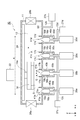
- FIG. 1 is a diagram schematically illustrating a film forming apparatus according to an embodiment.
- FIG. 1 shows an XYZ orthogonal coordinate system.
- a film forming apparatus 10 shown in FIG. 1 includes a processing container 11 that defines a processing chamber 12 that accommodates a substrate S, and a stage 14 that supports the substrate S.
- One surface (film formation surface) of the substrate S faces downward in the vertical direction (Z direction), for example. That is, the film forming apparatus 10 is a face-down type film forming apparatus.
- the stage 14 may incorporate an electrostatic chuck that attracts the substrate S.
- the film forming apparatus may be a type in which a gas containing vapor of a deposition material is blown onto the film forming surface facing upward, that is, a face-up type film forming apparatus.
- a vacuum pump 27b (second exhaust mechanism) is connected to the processing container 11 via an exhaust port 60 (second exhaust port) and a pipe 12b formed in the inner wall of the processing chamber 12, and the vacuum pump 27b The inside of the processing chamber 12 can be depressurized. Details of the formation position of the exhaust port 60 will be described later.
- the film forming apparatus 10 includes a vapor deposition head 16b having a nozzle 18b for spraying a gas G containing vapor of a vapor deposition material onto the substrate S.
- the film forming apparatus 10 may further include vapor deposition heads 16a, 16c, and 16d each having nozzles 18a, 18c, and 18d having the same structure as the nozzle 18b. From the nozzles 18a, 18c, and 18d, vapor deposition materials different from the vapor deposition material ejected from the nozzle 18b and different from each other may be ejected. Thereby, a plurality of types of films can be continuously deposited on the substrate S.
- the vapor deposition heads 16a to 16d are arranged in the X direction in the processing chamber 12. That is, the X direction is the direction in which the vapor deposition heads 16a to 16d are arranged side by side.
- the vapor deposition heads 16a to 16d are accommodated in box-shaped accommodation chambers 40a to 40d having openings 41a to 41d in the ejection direction, respectively.
- Each of the storage chambers 40a to 40d communicates with the processing chamber 12 through the openings 41a to 41d.
- steam partition walls 17a to 17d are erected so as to surround the openings 41a to 41d.
- the vapor deposition heads 16a to 16d are connected to gas supply sources 20a to 20d for supplying a gas containing vapor of the vapor deposition material, respectively.
- the gas G is supplied from the gas supply source 20b to the vapor deposition head 16b.
- circular injection ports are formed at the tips of the nozzles 18a to 18d. A gas containing a vapor deposition material is injected from the injection port.
- the gas supply sources 20a to 20d may be accommodated in the box-shaped accommodation chambers 40a to 40d, respectively.
- the film forming apparatus 10 includes a driving device (conveying unit) 22 that drives the stage 14 in the X direction that intersects the Y direction.
- the film forming apparatus 10 may further include a rail 24.
- the rail 24 is attached to the inner wall of the processing container 11.
- the stage 14 is connected to the rail 24 by, for example, a support portion 14a.
- the stage 14 and the support portion 14 a are moved by the drive device 22 so as to slide on the rail 24.
- the substrate S moves in the X direction relative to the nozzles 18a to 18d. That is, the transport path of the substrate S extends along the X direction (the direction in which the vapor deposition heads 16a to 16d are arranged side by side).
- the processing container 11 of the film forming apparatus 10 includes gate valves 26a and 26b.
- the substrate S can be introduced into the processing chamber 12 through the gate valve 26 a formed in the processing container 11, and can be carried out of the processing chamber 12 through the gate valve 26 b formed in the processing container 11.
- the film forming apparatus 10 includes a vacuum pump 27a (first exhaust mechanism) in addition to the vacuum pump 27b that decompresses the inside of the processing chamber 12.
- the vacuum pump 27a is connected to the processing chamber 12 via an exhaust port 50 (first exhaust port).
- the exhaust port 50 is an inner wall of the processing chamber 12 and is formed so as to be exposed to a space (deposition space) between the deposition surface of the substrate S and the deposition heads 16a to 16d.
- the transport path of the substrate S includes the processing section K in which the film formation surface of the substrate S faces the vapor deposition heads 16a to 16d, and the exhaust port 50 extends from the film formation surface to the arrangement position direction of the vapor deposition heads 16a to 16d.
- the exhaust port 50 is formed between the vapor deposition heads 16a to 16d.
- the exhaust port 50 may be provided at the center of the processing chamber 12. The pressure is likely to increase in the central portion of the processing chamber 12. For this reason, by providing the exhaust port 50 in the central portion of the processing chamber 12, the pressure can be efficiently reduced.
- the exhaust port 60 is provided on the inner wall of the processing chamber 12 at a position that does not overlap the processing section K when viewed from the film formation surface in the arrangement position direction (-Z direction) of the vapor deposition heads 16a to 16d.
- the vacuum pump 27 b may not be directly connected to the processing chamber 12. That is, a pump chamber or the like may be provided between the exhaust port 60 and the pipe 12b.
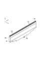
- FIG. 2 is a perspective view showing a vapor deposition head according to an embodiment.
- the vapor deposition head 16 b may have a plurality of injection ports 14 b in one embodiment. From the plurality of injection ports 14b, the gas supplied by the gas supply source 20b is injected to the center of the axis in the Z direction. These injection ports 14b can be arranged in a direction (Y direction) intersecting the moving direction (X direction) of the stage 14.
- the heater 15 may be incorporated in the vapor deposition head 16b. In one embodiment, the heater 15 heats the vapor deposition head 16b to a temperature at which the vapor deposition material supplied as vapor to the vapor deposition head 16b does not precipitate.
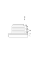
- FIG. 3 is a diagram illustrating an example of a completed state of an organic EL element that can be manufactured using the film forming apparatus according to an embodiment.
- the organic EL element D shown in FIG. 3 may include a substrate S, a first layer D1, a second layer D2, a third layer D3, a fourth layer D4, a fifth layer D5, and a sixth layer D6.
- the substrate S is an optically transparent substrate such as a glass substrate.
- a first layer D1 is provided on one main surface of the substrate S.
- the first layer D1 can be used as an anode layer.
- the first layer D1 is an optically transparent electrode layer, and may be formed of a conductive material such as ITO (Indium Tin Oxide).
- the first layer D1 is formed by, for example, a sputtering method.
- the second layer D2, the third layer D3, the fourth layer D4, and the fifth layer D5 are sequentially stacked on the first layer D1.
- the second layer D2, the third layer D3, the fourth layer D4, and the fifth layer D5 are organic layers.
- the second layer D2 can be a hole injection layer.
- the third layer D3 can include, for example, a non-light emitting layer D3a and a non-light emitting layer D3b.
- the fourth layer D4 can be a light emitting layer.
- the fifth layer D5 may be an electron transport layer.
- the second layer D2, the third layer D3, the fourth layer D4, and the fifth layer D5, which are organic layers, can be formed using the film forming apparatus 10.
- the sixth layer D6 is provided on the fifth layer D5.
- the sixth layer D6 is a cathode layer and can be made of, for example, Ag, Al, or the like.
- the sixth layer D6 can be formed by a sputtering method or the like.
- the element D having such a configuration can be further sealed with an insulating sealing film made of a material such as SiN formed by microwave plasma CVD or the like.
- the processing chamber 12 is depressurized through the exhaust port 50 formed in the inner wall of the processing chamber 12 at a position overlapping the processing section K in which vapor deposition is performed. .
- this configuration it is possible to efficiently suppress an increase in the pressure in the space between the vapor deposition heads 16a to 16d and the substrate S due to the gas ejected from the vapor deposition heads 16a to 16d.
- By sufficiently reducing the pressure in the vicinity of the vapor deposition heads 16a to 16d it becomes possible to reduce the diffusion and wraparound of material molecules between adjacent vapor deposition heads. Therefore, mixing of vapor
- the exhaust port 50 is formed so as to be exposed in the space between the film forming surface of the substrate S and the vapor deposition heads 16a to 16d, and the vacuum pump 27a is directly connected. Therefore, the pressure in the space can be efficiently reduced, and the diffusion and wraparound of material molecules between adjacent vapor deposition heads can be efficiently reduced.
- the film forming apparatus 10 according to the second embodiment is configured in substantially the same manner as the film forming apparatus 10 according to the first embodiment, and is different in that a vacuum pump 27c and a vacuum pump 27d are provided instead of the vacuum pump 27a.
- a vacuum pump 27c and a vacuum pump 27d are provided instead of the vacuum pump 27a.
- FIG. 4 is a diagram schematically showing a film forming apparatus according to an embodiment.
- FIG. 4 shows an XYZ orthogonal coordinate system.
- the film forming apparatus 10 shown in FIG. 4 includes a vacuum pump 27c (first exhaust mechanism) and a vacuum pump 27d (first exhaust mechanism) in addition to the vacuum pump 27b that decompresses the inside of the processing chamber 12.
- the vacuum pump 27c is connected to the storage chambers 40a to 40c for storing the vapor deposition heads 16a to 16c via the pipe 12c. That is, the vacuum pump 27c can be connected to a plurality of storage chambers.
- An opening 50a is formed at the bottom of the storage chamber 40a, and a tube 12c is connected to the storage chamber 40a.
- openings 50b and 50c are formed at the bottoms of the storage chambers 40b and 40c, and the pipe 12c is connected thereto. That is, the vacuum pump 27c is configured to depressurize each of the storage chambers 40a to 40c.
- the vacuum pump 27d is connected to a storage chamber 40d that stores the vapor deposition head 16d via a pipe 12d. That is, the vacuum pump 27d can be connected to a single storage chamber.
- An opening 50d is formed at the bottom of the storage chamber 40d, and the tube 12d is connected to the opening. That is, the vacuum pump 27d is configured to depressurize each storage chamber 40d.
- Each of the storage chambers 40a to 40d communicates with the processing chamber 12 through the openings 41a to 41d. That is, the vacuum pump 27c communicates with the processing chamber 12 through the opening 41a (first exhaust port), the opening 41b (first exhaust port), and the opening 41c (first exhaust port).
- the vacuum pump 27d communicates with the processing chamber 12 through an opening 41d (first exhaust port).
- the openings 41a to 41d are inner walls of the processing chamber 12 and are formed so as to be exposed to spaces (vapor deposition spaces) between the film formation surface of the substrate S and the vapor deposition heads 16a to 16d.
- the exhaust ports 50a to 50d are provided on the inner wall of the processing chamber 12 at a position overlapping the processing section K when viewed from the film formation surface in the direction of arrangement position of the vapor deposition heads 16a to 16d ( ⁇ Z direction).
- the gas supply sources 20a to 20d may be accommodated in box-shaped accommodation chambers 40a to 40d, respectively.
- FIG. 5 is a perspective view showing a vapor deposition head and a storage chamber according to an embodiment.
- the upper part of the storage chamber 40b is opened (opening 41b), and the vapor deposition head 16b is accommodated in the storage chamber 40b in a state where the ejection of the vapor deposition head 16b is not blocked.
- the size of the gap formed between the inner wall of the storage chamber 40b and the vapor deposition head 16b is defined as the width P1 of the storage chamber 40b and the width P3 of the vapor deposition head 16b. (P1-P3).
- the size of the gap formed between the inner wall of the storage chamber 40b and the vapor deposition head 16b in the direction parallel to the film formation surface and perpendicular to the X direction can be indicated by P2 as shown.
- P2> (P1-P3) the exhaust flow can be more easily generated in the direction along the Y direction than the exhaust flow is generated in the direction along the X direction.
- the processing chamber 12 is depressurized through the openings 41a to 41d formed in the inner wall of the processing chamber 12 at a position overlapping the processing section K in which vapor deposition is performed.
- the With this configuration it is possible to efficiently suppress an increase in the pressure in the space between the vapor deposition heads 16a to 16d and the substrate S due to the gas ejected from the vapor deposition heads 16a to 16d.
- By sufficiently reducing the pressure in the vicinity of the vapor deposition heads 16a to 16d it becomes possible to reduce the diffusion and wraparound of material molecules between adjacent vapor deposition heads. Therefore, mixing of vapor
- the vacuum pumps 27 c and 27 d are connected to the storage chambers 40 a to 40 d of the vapor deposition heads 16 a to 16 d communicating with the processing chamber 12, so that the substrate position It is possible to make the pressure and film formation distribution in the vicinity of the vapor deposition head constant without being affected by the above. Furthermore, since the vacuum pump 27c exhausts the plurality of storage chambers, it is possible to reduce the size of the entire apparatus as compared with the case where the vacuum pumps are arranged in all of the storage chambers.
- the film forming apparatus 10 according to the third embodiment is configured in substantially the same manner as the film forming apparatus 10 according to the first embodiment, and is different in that it includes elevating mechanisms (drive mechanisms) for the vapor deposition heads 16a to 16d. Below, it demonstrates centering around difference with 1st Embodiment, and the overlapping description is abbreviate
- FIG. 6 is a diagram schematically showing a film forming apparatus according to an embodiment.
- FIG. 6 shows an XYZ orthogonal coordinate system.
- the film forming apparatus 10 shown in FIG. 6 includes an elevating mechanism that changes the distance from the film forming surface by moving the vapor deposition heads 16a to 16d up and down in the Z direction.
- the elevating mechanism includes, for example, a drive unit that forms a connecting pipe between the vapor deposition heads 16a to 16d and the gas supply sources 20a to 20d with elastic members 42a to 42d such as bellows and generates a force in the vertical direction by a motor or the like.
- 43a to 43d are connected to the bottoms of the vapor deposition heads 16a to 16d.
- the diffusion distribution of vapor deposition can be controlled. For example, the shorter the distance between the film formation surface and the vapor deposition heads 16a to 16d by the lifting mechanism, the shorter the material diffusion distance.
- the concentration of the thin film layer may be extremely reduced. For this reason, for example, the operation timing and the operation amount of the lifting mechanism may be determined based on the difference in film thickness.
- the same effect as the effect according to the first embodiment can be obtained, and the material can reach the substrate before the jet spreads. It is possible to reduce diffusion and wraparound of material molecules between the vapor deposition heads. In addition, it is possible to more appropriately prevent a material mixture that becomes conspicuous when continuously forming films having greatly different thicknesses.
- Each embodiment described above shows an example of the film forming apparatus according to the present invention.
- the film forming apparatus according to the present invention is not limited to the film forming apparatus according to each embodiment, and the film forming apparatus according to each embodiment may be modified or applied to other devices.
- a shutter capable of blocking the vapor deposition material may be disposed at a position (opposite position) facing the nozzles 18a to 18d. Further, for example, the shutter may be rotated about the rotation axis along the Y direction, and may be disposed on the ejection ports of the nozzles 18a to 18d or may be retracted from the ejection ports as necessary.
- a plurality of exhaust ports 50 may be formed.
- a vacuum pump may be attached to each of the storage chambers 40a to 40d.
- ⁇ depends on the distance between the vapor deposition head and the substrate
- n depends on the pressure.
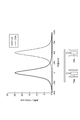
- a graph was created based on the above formula and experimental results. The results are shown in FIG. As shown in FIG. 7, it can be seen that the material is mixed at a position of 250 mm, which is an intermediate position between the vapor deposition head 16a and the vapor deposition head 16b. Therefore, it was confirmed that when no measures were taken, a mixed layer was formed between the second layer D2 and the third layer D3a.
- FIG. 8A shows a film forming profile with a chamber pressure of 0.03 Pa
- FIG. 8B shows an enlarged view of FIG. 8A
- FIG. 8C shows a chamber pressure of 0.
- the film formation profile is 01 Pa.
- 9A is a graph of the thickness dependency of the concentration calculated from FIG. 8B
- FIG. 9B is the thickness dependency of the concentration calculated from FIG. 8C. It is a graph. As shown in (B) and (C) of FIG.
- the second layer D2 since the film thickness difference is large between the second layer D2 and the third layer D3a, and between the third layer D3a and the third layer D3b, the second layer D2 The density was 98.5%, and the density of the third layer D3b was 99.1%, which was a low value.
- a graph of the thickness dependence of concentration was simulated with the film thickness and substrate distance shown in FIG. The results are shown in FIG. 10 (B) and FIG. 11 (B). As shown in FIG. 10B, it was confirmed that the concentration of the second layer D2 was improved to 99.9% and the concentration of the third layer D3b was improved to 99.9%. Therefore, it was confirmed that the mixing amount can be reduced by the elevating mechanism shown in the embodiment.
Landscapes
- Chemical & Material Sciences (AREA)
- Engineering & Computer Science (AREA)
- Chemical Kinetics & Catalysis (AREA)
- Materials Engineering (AREA)
- Mechanical Engineering (AREA)
- Metallurgy (AREA)
- Organic Chemistry (AREA)
- Manufacturing & Machinery (AREA)
- Physical Vapour Deposition (AREA)
- Electroluminescent Light Sources (AREA)
Abstract
成膜装置は、処理容器、複数の蒸着ヘッド、搬送部、第1排気機構を備えている。処理容器は、処理室を画成する。複数の蒸着ヘッドは、処理室内に並べて配置され、蒸着材料の蒸気を含むガスを噴射する。搬送部は、複数の蒸着ヘッドの並設方向に沿った搬送経路で、基板の成膜面を複数の蒸着ヘッドと対向させて基板を搬送する。第1排気機構は、処理室に第1排気口を介して接続される。ここで、搬送経路は、成膜面が複数の蒸着ヘッドと対向する処理区間を含み、第1排気口は、成膜面から蒸着ヘッドの配置位置方向にみて処理区間と重なる位置となる処理室の内壁に設けられている。
Description
本発明の一側面及び実施形態は、成膜装置に関するものである。
従来、気化された材料の蒸気を基板へ供給して成膜する装置が知られている(例えば特許文献1参照。)。特許文献1記載の装置は、基板を処理する処理室を画成する処理容器を備える。該処理容器内には、基板表面を下向きに向けた状態で基板を支持し、処理室内を水平方向に搬送する搬送機構、及び、基板搬送方向に沿って配置され、基板表面に対して成膜材料の蒸気を順に供給する複数の蒸着ヘッドが配置されている。各蒸着ヘッドには、成膜材料を含む蒸気を供給する蒸気発生室(ガス供給源)が接続されている。上述した処理室及び蒸気発生室は、互いに連通することなく、それぞれに接続された真空ポンプによって所定の圧力に減圧される。そして、各蒸着ヘッド間には、蒸気仕切り壁が設けられている。搬送機構によって搬送される基板には、各蒸着ヘッドの上方を通過中に各蒸着ヘッドから種々の材料が蒸着される。これにより基板上に積層体が形成される。
特許文献1記載の成膜装置のように、複数の蒸着ヘッドを並べて積層体を形成する場合には、隣接する蒸着ヘッド間において両者の蒸気の混入が発生するおそれがある。各蒸着ヘッド間に配置された蒸気仕切り壁は、このような蒸気の混入を防ぐために有効であるが、成膜条件によっては物理的な遮蔽のみでは十分でない場合がある。このため、本技術分野においては、隣接する蒸着ヘッド間における蒸気の混入をより適切に防ぐことができる成膜装置が望まれている。
本発明の一側面に係る成膜装置は、処理容器、複数の蒸着ヘッド、搬送部、第1排気機構を備えている。処理容器は、処理室を画成する。複数の蒸着ヘッドは、処理室内に並べて配置され、蒸着材料の蒸気を含むガスを噴射する。搬送部は、複数の蒸着ヘッドの並設方向に沿った搬送経路で、基板の成膜面を複数の蒸着ヘッドと対向させて基板を搬送する。第1排気機構は、処理室に第1排気口を介して接続される。ここで、搬送経路は、成膜面が複数の蒸着ヘッドと対向する処理区間を含み、第1排気口は、成膜面から蒸着ヘッドの配置位置方向にみて処理区間と重なる位置となる処理室の内壁に設けられている。
この成膜装置では、蒸着を行う処理区間と重なる位置であって処理室の内壁に形成された第1排気口を介して処理室が減圧される。このように構成することで、蒸着ヘッドから噴射されたガスによって蒸着ヘッドと基板との間の空間の圧力が上昇することを効率良く抑制することができる。蒸着ヘッド近傍の圧力を十分に下げることで、隣接する蒸着ヘッド間において材料分子の拡散や回り込みを低減することが可能となる。よって、隣接する蒸着ヘッド間における蒸気の混入をより適切に防ぐことができる。
一実施形態では、処理室に第2排気口を介して接続され、処理室を減圧する第2排気機構を備えてもよい。第2排気口は、成膜面から蒸着ヘッドの配置位置方向にみて処理区間と重ならない位置となる処理室の内壁に設けられていてもよい。このように、処理室全体の圧力を制御する排気機構を設けてもよい。
一実施形態では、第1排気口は、複数の蒸着ヘッドの間に形成されてもよい。処理室に直接的に排気機構を接続する構成とすることで、隣接する蒸着ヘッド間において材料分子の拡散や回り込みを効率的に低減することができる。
一実施形態では、各蒸着ヘッドは、噴射方向に開口を有する箱状の収容室に収容され、各収容室は、開口を介して処理室に連通され、第1排気機構が収容室に接続され、第1排気機構が接続された収容室の開口が第1排気口となってもよい。処理室に連通する蒸着ヘッドの収容室に排気機構を接続する構成とすることで、基板位置に影響を与えられることなく、蒸着ヘッド近傍の圧力及び成膜分布を一定にすることができる。
一実施形態では、第1排気機構が複数の収容室に接続されてもよい。このように構成することで、各収容室に排気機構を備える場合に比べて装置を小型化することができる。
一実施形態では、複数の蒸着ヘッドの並設方向における、収容室の内壁と蒸着ヘッドとの間に形成された間隙の大きさは、成膜面と平行でかつ複数の蒸着ヘッドの並設方向に直交する方向における、収容室の内壁と蒸着ヘッドとの間に形成された間隙の大きさよりも小さくてもよい。このように構成することで、蒸着ヘッドから噴射された材料が、蒸着ヘッドの並設方向よりも成膜面と平行でかつ複数の蒸着ヘッドの並設方向に直交する方向へ排気されるため、隣接する蒸着ヘッド間において材料分子の拡散や回り込みを低減することが可能となる。
一実施形態では、各蒸着ヘッドには、成膜面との距離を変更させる駆動機構が設けられていてもよい。このように構成することで、噴射が広がる前に基板へ材料を到達させることができるため、隣接する蒸着ヘッド間において材料分子の拡散や回り込みを低減することが可能となる。
一実施形態では、駆動機構は、第1蒸着ヘッドによって成膜した膜厚と第2蒸着ヘッドによって成膜すべき膜厚との差に基づいて第2蒸着ヘッドの成膜面との距離を変更させてもよい。このように構成することで、厚さが大きく異なる成膜を行う場合に顕著となる材料の混入をより適切に防ぐことができる。
以上説明したように、本発明の一側面及び実施形態によれば、隣接する蒸着ヘッド間における蒸気の混入をより適切に防ぐことができる。
以下、図面を参照して種々の実施形態について詳細に説明する。なお、各図面において同一又は相当の部分に対しては同一の符号を附すこととする。
(第1実施形態)
図1は、一実施形態に係る成膜装置を模式的に示す図である。図1には、XYZ直交座標系が示されている。図1に示す成膜装置10は、基板Sを収容する処理室12を画成する処理容器11と、基板Sを支持するステージ14とを備える。基板Sの一方の面(成膜面)は例えば鉛直方向(Z方向)において下を向いている。即ち、成膜装置10はフェースダウン型の成膜装置である。ステージ14は、基板Sを吸着する静電チャックを内蔵してもよい。なお、別の実施形態においては、成膜装置は、上に向いた成膜面に蒸着材料の蒸気を含むガスを吹き付ける型、即ち、フェースアップ型の成膜装置であってもよい。処理容器11には、処理室12の内壁に形成された排気口60(第2排気口)及び管12bを介して真空ポンプ27b(第2排気機構)が接続されており、当該真空ポンプ27bにより、処理室12内を減圧することができる。排気口60の形成位置の詳細については後述する。
図1は、一実施形態に係る成膜装置を模式的に示す図である。図1には、XYZ直交座標系が示されている。図1に示す成膜装置10は、基板Sを収容する処理室12を画成する処理容器11と、基板Sを支持するステージ14とを備える。基板Sの一方の面(成膜面)は例えば鉛直方向(Z方向)において下を向いている。即ち、成膜装置10はフェースダウン型の成膜装置である。ステージ14は、基板Sを吸着する静電チャックを内蔵してもよい。なお、別の実施形態においては、成膜装置は、上に向いた成膜面に蒸着材料の蒸気を含むガスを吹き付ける型、即ち、フェースアップ型の成膜装置であってもよい。処理容器11には、処理室12の内壁に形成された排気口60(第2排気口)及び管12bを介して真空ポンプ27b(第2排気機構)が接続されており、当該真空ポンプ27bにより、処理室12内を減圧することができる。排気口60の形成位置の詳細については後述する。
成膜装置10は、蒸着材料の蒸気を含むガスGを基板Sに噴き付けるノズル18bを有する蒸着ヘッド16bを備える。成膜装置10は、更に、ノズル18bと同様の構造を有するノズル18a,18c,18dをそれぞれ有する蒸着ヘッド16a,16c,16dを備えてもよい。ノズル18a,18c,18dからは、ノズル18bから噴き出される蒸着材料とは別の蒸着材料であって、かつ、互いに異なる蒸着材料を噴き出してもよい。これにより、基板S上に複数種類の膜を連続的に蒸着させることができる。蒸着ヘッド16a~16dは、処理室12内にX方向に並べて配置されている。すなわちX方向が蒸着ヘッド16a~16dの並設方向となる。
各蒸着ヘッド16a~16dは、噴射方向に開口41a~41dを有する箱状の収容室40a~40dにそれぞれ収容されている。各収容室40a~40dは、開口41a~41dを介して処理室12と連通されている。また、開口41a~41dを囲むように、蒸気仕切り壁17a~17dが立設されている。
蒸着ヘッド16a~16dには、蒸着材料の蒸気を含むガスを供給するガス供給源20a~20dがそれぞれ接続されている。例えば、ガス供給源20bからは、ガスGが蒸着ヘッド16bに供給される。ノズル18a~18dの先端には例えば円形の噴射口が形成されている。当該噴射口から蒸着材料を含むガスが噴射される。ここで、ガス供給源20a~20dが、それぞれ箱状の収容室40a~40dにそれぞれ収容されていても良い。
成膜装置10は、Y方向と交差するX方向にステージ14を駆動する駆動装置(搬送部)22を備える。また、成膜装置10は、レール24を更に備え得る。レール24は処理容器11の内壁に取り付けられている。ステージ14は、例えば支持部14aによってレール24に接続されている。ステージ14及び支持部14aは、駆動装置22によってレール24上をスライドするように移動する。これにより、ノズル18a~18dに対して相対的に基板SがX方向に移動する。すなわち基板Sの搬送経路は、X方向(蒸着ヘッド16a~16dの並設方向)に沿って延びている。基板Sは、X方向に移動することによって、ノズル18a~18dの開口に順番に対面配置されることとなる。図1における矢印Aはステージ14の移動方向を示している。また、成膜装置10の処理容器11は、ゲートバルブ26a及び26bを有している。基板Sは、処理容器11に形成されたゲートバルブ26aを通って処理室12内に導入可能であり、処理容器11に形成されたゲートバルブ26bを通って処理室12外に搬出可能である。
成膜装置10は、処理室12内を減圧する真空ポンプ27bの他に、真空ポンプ27a(第1排気機構)を備える。真空ポンプ27aは、処理室12に排気口50(第1排気口)を介して接続されている。排気口50は、処理室12の内壁であって、基板Sの成膜面と、蒸着ヘッド16a~16dとの間の空間(蒸着空間)に露出するように形成されている。すなわち、基板Sの搬送経路は、基板Sの成膜面が蒸着ヘッド16a~16dと対向する処理区間Kを含んでおり、排気口50は、成膜面から蒸着ヘッド16a~16dの配置位置方向(-Z方向)にみて処理区間Kと重なる位置となる処理室12の内壁に設けられている。さらに、排気口50は、蒸着ヘッド16a~16d間に形成されている。排気口50は、処理室12の中央部に設けられてもよい。処理室12の中央部は圧力が上昇しやすい。このため、排気口50を処理室12の中央部に設けることで、効率良く圧力を低下させることができる。
一方、排気口60は、成膜面から蒸着ヘッド16a~16dの配置位置方向(-Z方向)にみて処理区間Kと重ならない位置となる処理室12の内壁に設けられている。なお、真空ポンプ27bは、直接的に処理室12に接続されていなくてもよい。すなわち、排気口60と管12bとの間にポンプ室等を設けてもよい。
図2は、一実施形態に係る蒸着ヘッドを示す斜視図である。図2に示すように、蒸着ヘッド16bは、一実施形態においては、複数の噴射口14bを有し得る。複数の噴射口14bからは、ガス供給源20bによって供給されたガスがZ方向の軸線中心に噴射される。これら噴射口14bは、ステージ14の移動方向(X方向)に交差する方向(Y方向)に配列され得る。
また、蒸着ヘッド16bには、ヒータ15が内蔵され得る。一実施形態においては、ヒータ15は、蒸着ヘッド16bに蒸気として供給された蒸着材料が析出することがない温度まで、蒸着ヘッド16bを加熱する。
図3は、一実施形態に係る成膜装置を用いて製造され得る有機EL素子の完成状態の一例を示す図である。図3に示す有機EL素子Dは、基板S、第1層D1、第2層D2、第3層D3、第4層D4、第5層D5、及び第6層D6を備え得る。基板Sは、ガラス基板のような光学的に透明な基板である。
基板Sの一主面上には、第1層D1が設けられている。第1層D1は、陽極層として用いられ得る。この第1層D1は、光学的に透明な電極層であり、例えば、ITO(Indium Tin Oxide)のような導電性材料により構成され得る。第1層D1は、例えば、スパッタリング法により形成される。
第1層D1上には、第2層D2、第3層D3、第4層D4及び第5層D5が順に積層されている。第2層D2、第3層D3、第4層D4及び第5層D5は、有機層である。第2層D2は、ホール注入層で有り得る。第3層D3は、例えば、非発光層D3a、非発光層D3bを含み得る。また、第4層D4は、発光層であり得る。第5層D5は、電子輸送層であり得る。有機層である第2層D2、第3層D3、第4層D4及び第5層D5を、成膜装置10を用いて形成し得る。
第5層D5上には、第6層D6が設けられている。第6層D6は、陰極層であり、例えば、Ag、Al等により構成され得る。第6層D6は、スパッタリング法等により形成され得る。このような構成の素子Dは、更に、マイクロ波プラズマCVD等により形成されるSiNといった材料の絶縁性の封止膜によって封止され得る。
以上、第1実施形態に係る成膜装置10によれば、蒸着を行う処理区間Kと重なる位置であって処理室12の内壁に形成された排気口50を介して処理室12が減圧される。このように構成することで、蒸着ヘッド16a~16dから噴射されたガスによって蒸着ヘッド16a~16dと基板Sとの間の空間の圧力が上昇することを効率良く抑制することができる。蒸着ヘッド16a~16d近傍の圧力を十分に下げることで、隣接する蒸着ヘッド間において材料分子の拡散や回り込みを低減することが可能となる。よって、隣接する蒸着ヘッド間における蒸気の混入をより適切に防ぐことができる。
また、第1実施形態に係る成膜装置10によれば、排気口50が基板Sの成膜面と蒸着ヘッド16a~16dとの間の空間に露出するように形成され、真空ポンプ27aが直接的に処理室12に接続されているため、該空間の圧力を効率的に低下させ、隣接する蒸着ヘッド間において材料分子の拡散や回り込みを効率的に低減することができる。
(第2実施形態)
第2実施形態に係る成膜装置10は、第1実施形態に係る成膜装置10とほぼ同様に構成され、真空ポンプ27aに替えて真空ポンプ27c及び真空ポンプ27dを備える点が相違する。以下では、第1実施形態との相違点を中心に説明し、重複する説明は省略する。
第2実施形態に係る成膜装置10は、第1実施形態に係る成膜装置10とほぼ同様に構成され、真空ポンプ27aに替えて真空ポンプ27c及び真空ポンプ27dを備える点が相違する。以下では、第1実施形態との相違点を中心に説明し、重複する説明は省略する。
図4は、一実施形態に係る成膜装置を模式的に示す図である。図4には、XYZ直交座標系が示されている。図4に示す成膜装置10は、処理室12内を減圧する真空ポンプ27bの他に、真空ポンプ27c(第1排気機構)及び真空ポンプ27d(第1排気機構)を備える。真空ポンプ27cは、蒸着ヘッド16a~16cを収容する収容室40a~40cに管12cを介して接続されている。すなわち真空ポンプ27cは、複数の収容室に接続され得る。収容室40aの底部には、開口50aが形成されており、管12cが接続されている。同様に、収容室40b,40cの底部には、開口50b,50cが形成されており、管12cが接続されている。すなわち、真空ポンプ27cは、各収容室40a~40cを減圧する構成となっている。真空ポンプ27dは、蒸着ヘッド16dを収容する収容室40dに管12dを介して接続されている。すなわち真空ポンプ27dは、単一の収容室に接続され得る。収容室40dの底部には、開口50dが形成されており、管12dが接続されている。すなわち、真空ポンプ27dは、各収容室40dを減圧する構成となっている。
各収容室40a~40dは、開口41a~41dを介して処理室12と連通されている。すなわち、真空ポンプ27cは、開口41a(第1排気口)、開口41b(第1排気口)、開口41c(第1排気口)を介して処理室12と連通されている。真空ポンプ27dは、開口41d(第1排気口)を介して処理室12と連通されている。開口41a~41dは、処理室12の内壁であって、基板Sの成膜面と、蒸着ヘッド16a~16dとの間の空間(蒸着空間)に露出するように形成されている。排気口50a~50dは、成膜面から蒸着ヘッド16a~16dの配置位置方向(-Z方向)にみて処理区間Kと重なる位置となる処理室12の内壁に設けられている。ここで、ガス供給源20a~20dは、それぞれ箱状の収容室40a~40dにそれぞれ収容されていても良い。
図5は、一実施形態に係る蒸着ヘッド及び収容室を示す斜視図である。図5に示すように、収容室40bの上方は開口されており(開口41b)、蒸着ヘッド16bの噴射を遮らない状態で、収容室40bに蒸着ヘッド16bが収容されている。複数の蒸着ヘッドの並設方向であるX方向において、収容室40bの内壁と蒸着ヘッド16bとの間に形成された間隙の大きさは、収容室40bの幅P1と蒸着ヘッド16bの幅P3との差分(P1-P3)で算出される。一方、成膜面と平行でかつX方向に直交する方向において、収容室40bの内壁と蒸着ヘッド16bとの間に形成された間隙の大きさは、図示のとおりP2で示すことができる。ここで、P2>(P1-P3)とすることで、X方向に沿った方向へ排気流が生成されるよりも、Y方向に沿った方向へ排気流が生成されやすくすることができる。
以上、第2実施形態に係る成膜装置10によれば、蒸着を行う処理区間Kと重なる位置であって処理室12の内壁に形成された開口41a~41dを介して処理室12が減圧される。このように構成することで、蒸着ヘッド16a~16dから噴射されたガスによって蒸着ヘッド16a~16dと基板Sとの間の空間の圧力が上昇することを効率良く抑制することができる。蒸着ヘッド16a~16d近傍の圧力を十分に下げることで、隣接する蒸着ヘッド間において材料分子の拡散や回り込みを低減することが可能となる。よって、隣接する蒸着ヘッド間における蒸気の混入をより適切に防ぐことができる。
また、第2実施形態に係る成膜装置10によれば、処理室12に連通する蒸着ヘッド16a~16dの収容室40a~40dに真空ポンプ27c、27dを接続する構成とすることで、基板位置に影響を与えられることなく、蒸着ヘッド近傍の圧力及び成膜分布を一定にすることができる。さらに、真空ポンプ27cが複数の収容室を排気することで、収容室の全てに真空ポンプを配置する場合に比べて、装置全体の小型化を図ることが可能となる。
(第3実施形態)
第3実施形態に係る成膜装置10は、第1実施形態に係る成膜装置10とほぼ同様に構成され、蒸着ヘッド16a~16dの昇降機構(駆動機構)を備える点が相違する。以下では、第1実施形態との相違点を中心に説明し、重複する説明は省略する。
第3実施形態に係る成膜装置10は、第1実施形態に係る成膜装置10とほぼ同様に構成され、蒸着ヘッド16a~16dの昇降機構(駆動機構)を備える点が相違する。以下では、第1実施形態との相違点を中心に説明し、重複する説明は省略する。
図6は、一実施形態に係る成膜装置を模式的に示す図である。図6には、XYZ直交座標系が示されている。図6に示す成膜装置10は、蒸着ヘッド16a~16dをZ方向に上下動させることにより、成膜面との距離を変更させる昇降機構を備えている。昇降機構は、例えば、蒸着ヘッド16a~16dとガス供給源20a~20dとの接続管をベローズ等の伸縮自在な部材42a~42dで形成するとともに、モータ等により上下方向に力を発生させる駆動部43a~43dを蒸着ヘッド16a~16dの底部に接続することで構成される。
昇降機構によって成膜面と蒸着ヘッド16a~16dとの距離を制御することで、蒸着の拡散分布を制御することができる。例えば、昇降機構によって成膜面と蒸着ヘッド16a~16dとの距離を短く設定するほど、材料の拡散距離を短くすることができる。また、膜厚が薄い層と膜厚が厚い層とを連続的に成膜する場合には、膜厚が薄い層の濃度等が極端に低下するおそれがある。このため、例えば、膜厚さの差分に基づいて昇降機構の作動タイミングや作動量を決定してもよい。
以上、第3実施形態に係る成膜装置10によれば、第1実施形態に係る作用効果と同様の作用効果を奏するとともに、噴射が広がる前に基板へ材料を到達させることができるため、隣接する蒸着ヘッド間において材料分子の拡散や回り込みを低減することが可能となる。また、厚さが大きく異なる成膜を連続して行う場合に顕著となる材料の混入をより適切に防ぐことができる。
なお、上述した各実施形態は、本発明に係る成膜装置の一例を示すものである。本発明に係る成膜装置は、各実施形態に係る成膜装置に限られるものではなく、各実施形態に係る成膜装置を変形し、又は他のものに適用したものであってもよい。
例えば、ノズル18a~18dの噴射口との対面位置(対向位置)には、蒸着材料を遮断可能なシャッターがそれぞれ配置されてもよい。また、例えばY方向に沿った回転軸を中心にシャッターを回転させて、必要に応じてノズル18a~18dの噴射口上に配置したり当該噴射口上から退避させたりしてもよい。
また、第1実施形態において、排気口50は複数形成されてもよい。また、第2実施形態において、収容室40a~40dごとに真空ポンプを取り付けてもよい。
以下、上記効果を説明すべく本発明者が実施した実施例及び比較例について述べる。
(蒸着ヘッド間の材料混入確認)
蒸着ヘッド16aと蒸着ヘッド16bとの間の位置と、蒸着レート(成膜プロファイル)との関係をシミュレーションした。ここでは、蒸着ヘッド16aと蒸着ヘッド16bとの間が500mm離れているとした。また、蒸着ヘッド16aが図3の第2層D2を蒸着しているものとし、蒸着ヘッド16bが図3の第3層D3aを蒸着しているものとした。成膜プロファイルZ(X)は、Z0cosnθで表現される。Z0はX=0の場合のZ(X)の値を示す。θは、蒸着ヘッドと基板との距離に依存し、nは圧力に依存する。シミュレーションでは、上記式及び実験結果に基づいてグラフを作成した。結果を図7に示す。図7に示すように、蒸着ヘッド16aと蒸着ヘッド16bとの中間である250mmの位置で材料が混在していることがわかる。従って、何ら対策を取らない場合には、第2層D2と第3層D3aとの間で両者が混ざった層が形成されることが確認された。
蒸着ヘッド16aと蒸着ヘッド16bとの間の位置と、蒸着レート(成膜プロファイル)との関係をシミュレーションした。ここでは、蒸着ヘッド16aと蒸着ヘッド16bとの間が500mm離れているとした。また、蒸着ヘッド16aが図3の第2層D2を蒸着しているものとし、蒸着ヘッド16bが図3の第3層D3aを蒸着しているものとした。成膜プロファイルZ(X)は、Z0cosnθで表現される。Z0はX=0の場合のZ(X)の値を示す。θは、蒸着ヘッドと基板との距離に依存し、nは圧力に依存する。シミュレーションでは、上記式及び実験結果に基づいてグラフを作成した。結果を図7に示す。図7に示すように、蒸着ヘッド16aと蒸着ヘッド16bとの中間である250mmの位置で材料が混在していることがわかる。従って、何ら対策を取らない場合には、第2層D2と第3層D3aとの間で両者が混ざった層が形成されることが確認された。
(圧力調整による混入量の低減確認)
上記の蒸着ヘッド間の材料混入確認と同様の手法でシミュレーションした。ここではチャンバ圧力(成膜面と蒸着ヘッドとの間の圧力)を0.03Paと0.01Paとに調整して比較した。結果を図8に示す。図8の(A)は、チャンバ圧力が0.03Paの成膜プロファイル、図8の(B)は、図8の(A)の拡大図、図8の(C)は、チャンバ圧力が0.01Paの成膜プロファイルである。図9の(A)は、図8の(B)から算出した濃度の厚さ依存性のグラフ、図9の(B)は、図8の(C)から算出した濃度の厚さ依存性のグラフである。図8の(B),(C)、又は図9の(A),(B)に示すように、圧力を下げることによって材料の混入量が低減されることが確認された。また、図9の(A)に示すように、チャンバ圧力が0.03Paの場合、第2層D2の濃度の最大値は96.8%であった。一方、図9の(B)に示すように、チャンバ圧力が0.01Paの場合、第2層D2の濃度の最大値は99.3%となった。従って、実施形態に示す排気機構の位置、すなわちチャンバ圧力を下げやすい位置に排気機構を備えることが混入量の低減に有効であることが確認された。
上記の蒸着ヘッド間の材料混入確認と同様の手法でシミュレーションした。ここではチャンバ圧力(成膜面と蒸着ヘッドとの間の圧力)を0.03Paと0.01Paとに調整して比較した。結果を図8に示す。図8の(A)は、チャンバ圧力が0.03Paの成膜プロファイル、図8の(B)は、図8の(A)の拡大図、図8の(C)は、チャンバ圧力が0.01Paの成膜プロファイルである。図9の(A)は、図8の(B)から算出した濃度の厚さ依存性のグラフ、図9の(B)は、図8の(C)から算出した濃度の厚さ依存性のグラフである。図8の(B),(C)、又は図9の(A),(B)に示すように、圧力を下げることによって材料の混入量が低減されることが確認された。また、図9の(A)に示すように、チャンバ圧力が0.03Paの場合、第2層D2の濃度の最大値は96.8%であった。一方、図9の(B)に示すように、チャンバ圧力が0.01Paの場合、第2層D2の濃度の最大値は99.3%となった。従って、実施形態に示す排気機構の位置、すなわちチャンバ圧力を下げやすい位置に排気機構を備えることが混入量の低減に有効であることが確認された。
(蒸着ヘッド位置の制御による混入量の低減確認)
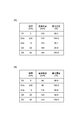
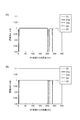
図3に示す有機EL素子Dの第2層D2、第3層D3a、第3層D3b、第4層D4、及び、第5層D5を積層するシミュレーションを行った。まず、比較例として、図10の(A)に示す膜厚、基板距離で濃度の厚さ依存性のグラフをシミュレーションした。結果を図10の(A)及び図11の(A)に示す。図10の(A)に示すように、第2層D2と第3層D3aとの間、第3層D3aと第3層D3bとの間で膜厚差が大きいために、第2層D2の濃度が98.5%、第3層D3bの濃度が99.1%と低い値となった。次に、実施例として、図10の(B)に示す膜厚、基板距離で濃度の厚さ依存性のグラフをシミュレーションした。結果を図10の(B)及び図11の(B)に示す。図10の(B)に示すように、第2層D2の濃度が99.9%、第3層D3bの濃度が99.9%と改善されることが確認された。従って、実施形態に示す昇降機構によって混入量の低減できることが確認された。
図3に示す有機EL素子Dの第2層D2、第3層D3a、第3層D3b、第4層D4、及び、第5層D5を積層するシミュレーションを行った。まず、比較例として、図10の(A)に示す膜厚、基板距離で濃度の厚さ依存性のグラフをシミュレーションした。結果を図10の(A)及び図11の(A)に示す。図10の(A)に示すように、第2層D2と第3層D3aとの間、第3層D3aと第3層D3bとの間で膜厚差が大きいために、第2層D2の濃度が98.5%、第3層D3bの濃度が99.1%と低い値となった。次に、実施例として、図10の(B)に示す膜厚、基板距離で濃度の厚さ依存性のグラフをシミュレーションした。結果を図10の(B)及び図11の(B)に示す。図10の(B)に示すように、第2層D2の濃度が99.9%、第3層D3bの濃度が99.9%と改善されることが確認された。従って、実施形態に示す昇降機構によって混入量の低減できることが確認された。
10…成膜装置、11…処理容器、12…処理室、16a~16d…蒸着ヘッド、20a~20d…ガス供給源、22…駆動装置(搬送部)、27a、27c、27d…真空ポンプ(第1排気機構)、27b…真空ポンプ(第2排気機構)、K…処理区間、S…基板。
Claims (8)
- 処理室を画成する処理容器と、
前記処理室内に並べて配置され、蒸着材料の蒸気を含むガスを噴射する複数の蒸着ヘッドと、
前記複数の蒸着ヘッドの並設方向に沿った搬送経路で、基板の成膜面を前記複数の蒸着ヘッドと対向させて前記基板を搬送する搬送部と、
前記処理室に第1排気口を介して接続された第1排気機構と、
を備え、
前記搬送経路は、前記成膜面が前記複数の蒸着ヘッドと対向する処理区間を含み、
前記第1排気口は、前記成膜面から蒸着ヘッドの配置位置方向にみて前記処理区間と重なる位置となる前記処理室の内壁に設けられている成膜装置。 - 前記処理室に第2排気口を介して接続され、前記処理室を減圧する第2排気機構を備え、
前記第2排気口は、前記成膜面から蒸着ヘッドの配置位置方向にみて前記処理区間と重ならない位置となる前記処理室の内壁に設けられている請求項1に記載の成膜装置。 - 前記第1排気口は、前記複数の蒸着ヘッドの間に形成される請求項1又は2に記載の成膜装置。
- 各蒸着ヘッドは、噴射方向に開口を有する箱状の収容室に収容され、
各収容室は、前記開口を介して前記処理室に連通され、前記第1排気機構が前記収容室に接続され、
前記第1排気機構が接続された前記収容室の開口が前記第1排気口となる請求項1又は2に記載の成膜装置。 - 前記第1排気機構が複数の収容室に接続される請求項4に記載の成膜装置。
- 前記複数の蒸着ヘッドの並設方向における、前記収容室の内壁と前記蒸着ヘッドとの間に形成された間隙の大きさは、前記成膜面と平行でかつ前記複数の蒸着ヘッドの並設方向に直交する方向における、前記収容室の内壁と前記蒸着ヘッドとの間に形成された間隙の大きさよりも小さい請求項4又は5に記載の成膜装置。
- 各蒸着ヘッドには、前記成膜面との距離を変更させる駆動機構が設けられている請求項1~6の何れか一項に記載の成膜装置。
- 前記駆動機構は、第1蒸着ヘッドによって成膜した膜厚と第2蒸着ヘッドによって成膜すべき膜厚との差に基づいて前記第2蒸着ヘッドの前記成膜面との距離を変更させる請求項7に記載の成膜装置。
Applications Claiming Priority (2)
| Application Number | Priority Date | Filing Date | Title |
|---|---|---|---|
| JP2012162838A JP2014019942A (ja) | 2012-07-23 | 2012-07-23 | 成膜装置 |
| JP2012-162838 | 2012-07-23 |
Publications (1)
| Publication Number | Publication Date |
|---|---|
| WO2014017131A1 true WO2014017131A1 (ja) | 2014-01-30 |
Family
ID=49996950
Family Applications (1)
| Application Number | Title | Priority Date | Filing Date |
|---|---|---|---|
| PCT/JP2013/061226 Ceased WO2014017131A1 (ja) | 2012-07-23 | 2013-04-15 | 成膜装置 |
Country Status (3)
| Country | Link |
|---|---|
| JP (1) | JP2014019942A (ja) |
| TW (1) | TW201420790A (ja) |
| WO (1) | WO2014017131A1 (ja) |
Families Citing this family (1)
| Publication number | Priority date | Publication date | Assignee | Title |
|---|---|---|---|---|
| JP6087267B2 (ja) * | 2013-12-06 | 2017-03-01 | シャープ株式会社 | 蒸着装置、蒸着方法、及び、有機エレクトロルミネッセンス素子の製造方法 |
Citations (4)
| Publication number | Priority date | Publication date | Assignee | Title |
|---|---|---|---|---|
| JPH06340965A (ja) * | 1992-09-30 | 1994-12-13 | Sony Corp | 電子ビーム蒸着装置及び減圧方法、真空装置 |
| WO2007029671A1 (ja) * | 2005-09-06 | 2007-03-15 | Tohoku University | 成膜装置、成膜装置系、成膜方法、及び電子装置または有機エレクトロルミネッセンス素子の製造方法 |
| JP2008140669A (ja) * | 2006-12-04 | 2008-06-19 | Canon Inc | 真空蒸着装置および真空蒸着方法 |
| JP2010242171A (ja) * | 2009-04-07 | 2010-10-28 | Seiko Epson Corp | 蒸着装置 |
-
2012
- 2012-07-23 JP JP2012162838A patent/JP2014019942A/ja active Pending
-
2013
- 2013-04-15 WO PCT/JP2013/061226 patent/WO2014017131A1/ja not_active Ceased
- 2013-07-22 TW TW102126044A patent/TW201420790A/zh unknown
Patent Citations (4)
| Publication number | Priority date | Publication date | Assignee | Title |
|---|---|---|---|---|
| JPH06340965A (ja) * | 1992-09-30 | 1994-12-13 | Sony Corp | 電子ビーム蒸着装置及び減圧方法、真空装置 |
| WO2007029671A1 (ja) * | 2005-09-06 | 2007-03-15 | Tohoku University | 成膜装置、成膜装置系、成膜方法、及び電子装置または有機エレクトロルミネッセンス素子の製造方法 |
| JP2008140669A (ja) * | 2006-12-04 | 2008-06-19 | Canon Inc | 真空蒸着装置および真空蒸着方法 |
| JP2010242171A (ja) * | 2009-04-07 | 2010-10-28 | Seiko Epson Corp | 蒸着装置 |
Also Published As
| Publication number | Publication date |
|---|---|
| JP2014019942A (ja) | 2014-02-03 |
| TW201420790A (zh) | 2014-06-01 |
Similar Documents
| Publication | Publication Date | Title |
|---|---|---|
| JP6429491B2 (ja) | 蒸着装置用マスク、蒸着装置、蒸着方法、及び、有機エレクトロルミネッセンス素子の製造方法 | |
| CN102202992A (zh) | 基板处理系统 | |
| WO2012118199A1 (ja) | 蒸着装置、蒸着方法、有機elディスプレイ、及び照明装置 | |
| KR102595355B1 (ko) | 증착 장치 및 그것을 이용한 증착 방법 | |
| KR101006583B1 (ko) | 수평 배치형 원자층 증착 장치 | |
| KR20140060236A (ko) | 성막 장치 | |
| JP2013206820A (ja) | 有機elデバイス製造装置及び有機elデバイス製造方法 | |
| JP2013206820A6 (ja) | 有機elデバイス製造装置及び有機elデバイス製造方法 | |
| JP2008088483A (ja) | 蒸着装置およびその運転方法 | |
| WO2014017131A1 (ja) | 成膜装置 | |
| KR101754260B1 (ko) | 건조 장치 및 건조 처리 방법 | |
| US10944082B2 (en) | Vapor deposition apparatus | |
| JP2008088489A (ja) | 蒸着装置 | |
| KR20110104219A (ko) | 가스분사 유닛 및 이를 구비하는 직립방식 증착장치 | |
| KR101088828B1 (ko) | 유기 el의 성막 장치 및 증착 장치 | |
| WO2012127982A1 (ja) | 成膜装置、成膜方法、有機発光素子の製造方法、及び有機発光素子 | |
| KR101213965B1 (ko) | 스핀노즐 방식의 가스분사 유닛 및 이를 구비하는 직립방식 증착장치 | |
| KR101129058B1 (ko) | 분사홀이 나선형으로 배치된 스핀노즐 유닛 및 이를 구비하는 직립방식 증착장치 | |
| KR20130068926A (ko) | 증발원 및 이를 구비한 진공 증착 장치 | |
| KR102374023B1 (ko) | 기판처리장치 | |
| KR20120046864A (ko) | 타원형 유로를 갖는 가스분사 모듈 및 직립방식 증착장치 | |
| WO2014034499A1 (ja) | 蒸着装置、蒸着方法、有機elディスプレイ、および有機el照明装置 | |
| KR101687303B1 (ko) | 기판 증착시스템 | |
| KR20140140524A (ko) | 박막증착장치 | |
| KR20120066852A (ko) | 박막 증착장치 |
Legal Events
| Date | Code | Title | Description |
|---|---|---|---|
| 121 | Ep: the epo has been informed by wipo that ep was designated in this application |
Ref document number: 13823029 Country of ref document: EP Kind code of ref document: A1 |
|
| NENP | Non-entry into the national phase |
Ref country code: DE |
|
| 122 | Ep: pct application non-entry in european phase |
Ref document number: 13823029 Country of ref document: EP Kind code of ref document: A1 |