WO2014016952A1 - プローブ顕微鏡用ホルダ、プローブ顕微鏡および試料計測方法 - Google Patents
プローブ顕微鏡用ホルダ、プローブ顕微鏡および試料計測方法 Download PDFInfo
- Publication number
- WO2014016952A1 WO2014016952A1 PCT/JP2012/069079 JP2012069079W WO2014016952A1 WO 2014016952 A1 WO2014016952 A1 WO 2014016952A1 JP 2012069079 W JP2012069079 W JP 2012069079W WO 2014016952 A1 WO2014016952 A1 WO 2014016952A1
- Authority
- WO
- WIPO (PCT)
- Prior art keywords
- holder
- measurement
- probe
- sample
- container
- Prior art date
- Legal status (The legal status is an assumption and is not a legal conclusion. Google has not performed a legal analysis and makes no representation as to the accuracy of the status listed.)
- Ceased
Links
Images






Classifications
-
- G—PHYSICS
- G01—MEASURING; TESTING
- G01Q—SCANNING-PROBE TECHNIQUES OR APPARATUS; APPLICATIONS OF SCANNING-PROBE TECHNIQUES, e.g. SCANNING PROBE MICROSCOPY [SPM]
- G01Q30/00—Auxiliary means serving to assist or improve the scanning probe techniques or apparatus, e.g. display or data processing devices
- G01Q30/20—Sample handling devices or methods
-
- G—PHYSICS
- G01—MEASURING; TESTING
- G01Q—SCANNING-PROBE TECHNIQUES OR APPARATUS; APPLICATIONS OF SCANNING-PROBE TECHNIQUES, e.g. SCANNING PROBE MICROSCOPY [SPM]
- G01Q30/00—Auxiliary means serving to assist or improve the scanning probe techniques or apparatus, e.g. display or data processing devices
- G01Q30/02—Non-SPM analysing devices, e.g. SEM [Scanning Electron Microscope], spectrometer or optical microscope
-
- G—PHYSICS
- G01—MEASURING; TESTING
- G01Q—SCANNING-PROBE TECHNIQUES OR APPARATUS; APPLICATIONS OF SCANNING-PROBE TECHNIQUES, e.g. SCANNING PROBE MICROSCOPY [SPM]
- G01Q30/00—Auxiliary means serving to assist or improve the scanning probe techniques or apparatus, e.g. display or data processing devices
- G01Q30/08—Means for establishing or regulating a desired environmental condition within a sample chamber
- G01Q30/10—Thermal environment
-
- G—PHYSICS
- G01—MEASURING; TESTING
- G01Q—SCANNING-PROBE TECHNIQUES OR APPARATUS; APPLICATIONS OF SCANNING-PROBE TECHNIQUES, e.g. SCANNING PROBE MICROSCOPY [SPM]
- G01Q30/00—Auxiliary means serving to assist or improve the scanning probe techniques or apparatus, e.g. display or data processing devices
- G01Q30/08—Means for establishing or regulating a desired environmental condition within a sample chamber
- G01Q30/12—Fluid environment
- G01Q30/14—Liquid environment
-
- G—PHYSICS
- G01—MEASURING; TESTING
- G01Q—SCANNING-PROBE TECHNIQUES OR APPARATUS; APPLICATIONS OF SCANNING-PROBE TECHNIQUES, e.g. SCANNING PROBE MICROSCOPY [SPM]
- G01Q60/00—Particular types of SPM [Scanning Probe Microscopy] or microscopes; Essential components thereof
- G01Q60/24—AFM [Atomic Force Microscopy] or apparatus therefor, e.g. AFM probes
Definitions
- the present invention relates to a holder for arranging a sample, a probe microscope using the holder, and a sample measurement method using the microscope in a microscope for measuring a living tissue or the like with high spatial resolution.
- Hydration phenomena such as biomolecules, biological tissues, and biological substrate materials are important when measuring, evaluating, and controlling biological reactions such as cell adhesion to the biological substrate material in the culture medium and subsequent extension / differentiation.
- the hydration structure is formed from the interaction between the sample surface and water molecules and the interaction including hydrogen bonds between the water molecules at the sample-culture solution interface in the culture solution containing water as a main component. 3D structure is shown (Non-Patent Document 1). So-called biocompatibility represented by adhesion between the inner wall of an artificial blood vessel and erythrocytes is considered to be closely related to this hydration structure.
- unevenness of the sample surface in the culture medium, potential distribution, composition distribution and arrangement structure of molecules and proteins, etc. are particularly important for biological reactions such as biomolecules, biological tissues, and biological substrate materials in the culture medium. It is a characteristic.
- optical microscope, Raman spectroscopy, second harmonic method, sum frequency spectroscopy are methods for observing and measuring the sample-culture solution interface such as biomolecules, biological tissues, and biological substrate materials in the culture solution.
- Nonlinear optical microscopes such as are used.
- sum frequency spectroscopy can measure the arrangement of water molecules related to the hydration structure at the sample-culture liquid interface.
- a non-linear optical microscope for example, in Patent Document 1, the interaction between a probe and a target is expressed by surface selectivity by water molecules, solvent molecules near the interface, or second harmonic light or sum frequency light by a labeling substance.
- Non-linear optical methods are disclosed.
- the scanning probe microscope is based on an atomic force microscope (AFM: Atomic Force Microscope).
- the scanning Kelvin probe microscope which is an example of a scanning probe microscope, scans the probe surface on the sample surface while detecting the electrostatic field force acting between the cantilever with the conductive probe and the sample as the deflection of the cantilever. This is a technique for mapping the electrostatic field force distribution.
- the probe also includes interatomic forces and the like, and the electrostatic field forces need to be separated from other interactions. For this purpose, first, the cantilever is vibrated, and the distance between the probe and the sample is adjusted so as to keep the vibration amplitude reduced by the atomic force acting when the probe and the sample are in contact with each other.
- Sum-Frequency Microscope which is a typical nonlinear optical microscope, uses a laser-based sum-frequency microscope (Sum-Frequency-Microscope). Used to explore. However, the spatial resolution is about 1 ⁇ m, and a fine structure cannot be observed.
- the scanning probe microscope can be operated in a culture solution, and a high resolution of about 10 nm can be obtained by a relatively simple operation.
- the probe in order to detect the position of the sample surface, the probe must be brought into contact with the sample surface. If the tip of the probe is destroyed or the sample surface adheres during measurement, the detected signal is not good. There was a problem of becoming stable.
- a container that accommodates a measurement object such as a cell, a first lid that covers at least a part of the measurement object and has an opening for inserting a measurement probe, It was made into the shape used as the measurement holder which has the 2nd cover part which connects with 1 cover part, covers the said container, and has the opening part for measurement probe insertion.
- the present invention it is possible to maintain a good state of the sample without evaporating the culture solution or the like, so that the biomolecule / biological tissue / biological substrate material is maintained in the culture solution while maintaining the cell survival conditions. It is possible to measure the degree of orientation of water molecules at the interface of water and the like with high spatial resolution, and it is possible to identify the aggregation position and function of a specific element in a cell or cell mass.
- Holder structure disclosed in the present invention (1) Example of probe microscope configuration diagram Holder structure disclosed in the present invention (2) Holder structure disclosed in the present invention (3) Holder structure disclosed in the present invention (4) Changes in heart rate of cultured cardiomyocytes over time Holder structure disclosed in the present invention (5) Holder structure disclosed in the present invention (6) Holder structure disclosed in the present invention (7) Holder structure disclosed in the present invention (8) Holder structure disclosed in the present invention (9) Holder structure disclosed in the present invention (10)
- the present invention discloses a structure of a sample holder for measuring a biological sample / water sample typified by cells and water in a probe microscope.
- a scanning probe microscope scanning Kelvin probe microscope
- a probe-enhanced scanning sum-frequency microscope as one form of a scanning probe microscope is disclosed.
- the probe 1 is installed on the vibrator 2, and the relative position to the sample 3 is controlled by the vibrator 2.
- the probe 1 is selected from a material that amplifies and concentrates near-field light intensity near the tip when placed in incident light.
- Raman scattering such as Raman spectroscopy or sum frequency spectroscopy
- metals such as gold, silver, copper, and aluminum, and compounds thereof, which can effectively use surface-enhanced Raman scattering, are used.
- a probe obtained by depositing a gold thin film with a thickness of 1 to 20 nm on a silicon probe is used as an effective probe candidate.
- the vibrator 2 vibrates mainly in the vertical direction of the sample 3, the distance between the probe 1 and the sample 3 is controlled to 300 nm or less, and the natural frequency of the vibrator 2 is 200 kHz to 2 MHz is used.
- a quartz crystal vibrator that expands and contracts in the longitudinal direction is used as the vibrator 2.
- a tuning fork type crystal vibrator that is generally used in a scanning probe microscope such as an atomic force microscope, or vibration caused by a piezo element.
- a vibrator in which a piezo element is arranged on a child or a cantilever can be used.
- the probe 1 is vibrated in a direction perpendicular to the surface of the sample 3 by the vibrator 2 at a frequency near the natural frequency of the vibrator 2 (within about ⁇ 1% of the natural frequency). Due to the interaction (force) between the probe 1 and the sample 3, there is a phase difference between the voltage applied to the vibrator 2 and the actual vibration amplitude of the vibrator 2.
- the phase difference in this embodiment From the phase difference between the AC voltage applied to the vibrator 2 and the current flowing into the vibrator 2, the interaction (force) between the probe and the sample is known, and the distance between the probe and the sample is known.
- the scanning mechanism 4 scans the relative position between the sample 3 and the probe 1 in the direction perpendicular to the sample and in the plane direction of the sample.
- a force microscope A force microscope
- the distance between the probe 1 and the sample 3 is generally close to a distance of 0 nm (contact) to 100 nm at the closest position, but the probe 1 can be embedded into the sample 3.
- the probe 2 scans the relative position between the sample 3 and the probe 1 in the vertical direction and the plane direction of the sample by the scanning mechanism while reducing the vibration amplitude of the vibrator 2 by a certain amount.
- the distance between 1 and the sample 3 can be set to 0 nm at the closest position (tapping mode AFM).
- the sample holder 5 can hold and exchange the culture solution 6.
- water or a solvent can be used in place of the culture solution 6.
- a pulsed laser beam or a plurality of pulsed laser beams that are input in synchronism are input in the vicinity of the region of the sample 3 where the probe 1 is close, and the intensity of the output beam 8 is measured by the detector with filter 7.
- a first pulse laser beam 9 that is a green pulse laser beam having a wavelength of 532 nm
- a second pulse laser beam 10 that is a variable infrared pulse laser beam having a wavelength of 2.3 to 10 microns are included.
- Input synchronously.
- the output light 8 is input to the detector with filter 7 and the intensity of the sum of the frequency of the first pulse laser light 9 and the frequency of the second pulse laser light 10 (sum frequency) is measured.
- sum frequency spectroscopy can be performed.
- the peak of the wave number 3200 Kaiser and the peak of the wave number 3400 Kaiser are compared, and the ratio of the orientation of the water molecules asymmetrically bonded to the tetrahedrally coordinated water molecules at the interface between the polycarbonate and the culture solution 14 is calculated. Can be identified.
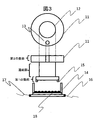
- FIG. 1 The structure of the sample holder necessary for this realization is shown in FIG.
- a cylindrical hole is provided inside the holder.
- a cover 11 has a cylindrical hole 12 at the center thereof.
- Reference numeral 13 denotes an inlet for a culture solution, which is used to maintain the temperature of the holder during measurement (about 37 ° C. is preferable, but not limited to this temperature). It is provided to replenish water. Moreover, when a liquid (culture solution) deteriorates, it can utilize also for discharging
- FIG. 14 is a holder body (container), which is fixed by a cylindrical hole 12 and a spacer 15.
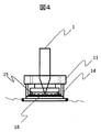
- FIG. 3 is a side view of FIG.
- a holder cover 11, a cylindrical hole 12, and a culture solution inlet 13 are provided concentrically, and a spacer 15 is provided at the lower part of the cylindrical hole.
- the 1st cover part which covers a part of sample 18 the 2nd cover part (holder cover) 11 which covers the holder main body 14, and the connection which connects a 1st cover part and a 2nd cover part It is the shape which provided the part.
- the first lid portion is provided with a hole 26 through which the probe 1 is passed, and the second lid portion (holder cover) 11 is also provided with a hole 12 through which the probe 1 is passed.
- the connecting part is hollow.
- first lid portion, connecting portion, and second lid portion are connected to the holder body 14.
- the spacer 15 is provided as a clog corresponding to the height of the sample 18, but when the sample is flat or the like, the spacer 26 is not necessarily required because of the hole 26. 1 and 3, the shape like the spacer 15 is illustrated. However, since it is a clog, it may be any shape.
- the hole 12 may have any other shape as long as the probe passes therethrough.
- the shape of the culture medium inlet 13 does not have to be circular, and may be any shape.
- the holder main body 14 has a cylindrical shape
- the holder cover also has a cylindrical shape.
- the holder main body only needs to hold the sample 18, and thus the holder main body 14 is not limited to the cylindrical shape, and may have any shape. Accordingly, the holder cover 11 is also connected to the holder 14 in an arbitrary shape.
- a heater for heating is not essential.
- a heater 16 is connected to the holder body 14 to maintain the temperature of the sample holder.
- a temperature sensor 17 composed of a Peltier element or the like is connected.
- a sample 18 typified by cells and water can be disposed on the holder body.
- the heater structure 16 can be repeatedly used even if the holder main body is discarded as a consumable item, which is advantageous in terms of cost. There is.
- FIG. 4 is an actual holder mounting diagram.
- the holder cover 11 and the holder main body 14 are in close contact with each other, and the spacer 15 is held in a state where it is in light contact with the sample 18.
- the probe 1 passing through the cylindrical hole 12 can approach the sample through the holder or spacer.
- FIG. 5 shows the actual usage of the holder shown up to FIG.
- Reference numeral 19 denotes a control device for the probe microscope, which processes the position of the probe 1 and the amount of light that has reached the detector with filter 7.
- 20 is a heater control device
- 21 is a temperature sensor detection device.
- the heater control device shown in 20 and the temperature sensor detection device shown in 21 are connected to each other, and can be set to a predetermined desired temperature by controlling the temperature by a feedback system.
- the information of the set temperature and the detected temperature, and the control device 19 of the probe microscope are also connected to each other, and the computer 22 is a hub for transmitting these information.
- the heart rate of the cultured myocardium of the rat was image-measured.
- the heater 16 was heated as advance preparation.
- the sample kit 18 was placed in the holder 14 and immersed in the culture solution, and then the holder cover 11 was set via the spacer 15. Then, the surface shape and the state of the cells were observed for less than 1 hour using the vibrator 2, the probe 1, and the pulse irradiation light while the temperature of the holder was kept substantially constant by the heater 16 and the sensor 17. Occasionally, the medium was replenished through the hole 13. The result is shown in FIG.
- the set temperature was 39 ° C., but the temperature on the holder surface was 37 ° C.
- FIG. 1 a modification of the holder will be shown.
- water or a culture solution is put from above the holder cover.
- the culture solution may be deteriorated, and it is necessary to provide a structure that avoids interference with the probe of the probe microscope.
- FIGS. 1 a method for more easily realizing the injection and recovery of water / culture solution is disclosed in FIGS.
- FIG. 7 discloses a holder characterized by including a culture solution discharge port 23 in addition to the culture solution intake port 13.
- the discharge port 23 is provided on the side surface of the holder. This is because, as described above, it is possible to easily discharge the deteriorated liquid inside the holder without hindering the approach of the probe approaching from above.
- FIG. 8 discloses a structure characterized in that a culture medium inlet 13 is also provided on the side of the holder.
- a culture medium inlet 13 is also provided on the side of the holder.
- supplementing and collecting the culture solution has the effect of allowing the measurement to be performed while maintaining the survival state even when the measurement requires a longer time.
- a modified example related to the temperature measurement execution method will be shown for the holder.
- the heater is installed in the lower part of the sample holder, and the heater and the temperature sensor are integrated.
- an invention relating to the arrangement position of the sensor is disclosed.
- FIG. 9 includes a structure for inserting the temperature sensor 17 into the holder body. This makes it possible to measure the temperature of the sample 3 in a form that correctly reflects the heat conduction characteristics of the holder made of a plastic material or the like.
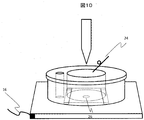
- FIG. 10 discloses a sample holder that is characterized by measuring the temperature of the surface of the sample 3 using the optical fiber sensor 24. With this method, it is not necessary to attach the temperature sensor 17 to the sample holder 5, and a simpler sample holder can be realized.
- FIG. 11 discloses a structure of the sample holder 5 in which the sample holder 5 is heated by irradiation of an electromagnetic wave typified by laser or light using an optical fiber 25 as an alternative to the heater 16.
- the wavelength of the laser used for actual irradiation is preferably an infrared wavelength band or an absorption wavelength body possessed by the material of the sample holder.
- the holder mounting / removal structure is shown in FIG.
- the holder cover 11 detachable from the holder main body 14 and the spacer 15
- the top and bottom of FIG. 12 can be washed and used repeatedly.
- cells can respire, and measurement can be performed for a long time while maintaining a high survival condition.
Landscapes
- Physics & Mathematics (AREA)
- Health & Medical Sciences (AREA)
- General Health & Medical Sciences (AREA)
- General Physics & Mathematics (AREA)
- Nuclear Medicine, Radiotherapy & Molecular Imaging (AREA)
- Radiology & Medical Imaging (AREA)
- Apparatus Associated With Microorganisms And Enzymes (AREA)
Description
2 振動子
3 試料
4 走査機構
5 試料ホルダ
6 培養液
7 フィルター付検出器
8 出力光
9 第一のパルスレーザ光
10 第二のパルスレーザ光
11 ホルダカバー
12 円筒状の穴
13 培養液の取り入れ口
14 ホルダ本体
15 スペーサー
16 ヒータ
17 温度センサー
18 試料
19 プローブ顕微鏡の制御装置
20 ヒータの制御装置
21 温度センサーの検出装置
22 電子計算機
23 培養液の排出口
24 光ファイバセンサ
25 電磁波照射用光ファイバ
26 穴
Claims (13)
- 計測対象物を内部に収容する容器と、
前記計測対象物の少なくとも一部を覆い、かつ計測用プローブ挿入用の開口部を有する第1の蓋部と、
前記第1の蓋部と連結し、前記容器を覆い、かつ、計測用プローブ挿入用の開口部を有する第2の蓋部とを有することを特徴とする計測用ホルダ。 - 前記第1の蓋部には、前記容器側に、前記容器から所定の高さを保つためのスペーサーが形成されていることを特徴とする請求項1記載の計測用ホルダ。
- 前記第2の蓋部には、液体注入及び/または液体排出用の穴が形成されていることを特徴とする請求項1記載の計測用ホルダ。
- 前記穴の配置位置は、前記第2の蓋部の上部であることを特徴とする請求項3記載の計測用ホルダ。
- 前記穴の配置位置は、前記容器の側部であることを特徴とする請求項3記載の計測用ホルダ。
- さらに、前記容器を加熱するための加熱用素子が設けられていることを特徴とする請求項1記載の計測用ホルダ。
- さらに、前記容器の温度を計測するための温度計測用センサーを具備することを特徴とする請求項6記載の計測用ホルダ。
- 前記加熱用素子及び/または前記温度計測用センサーは、前記容器からの着脱式であることを特徴とする請求項7記載の計測用ホルダ。
- 前記加熱用素子は、前記容器に設けられていることを特徴とする請求項6記載の計測用ホルダ。
- 前記加熱用素子は光ファイバであることを特徴とする請求項6記載の計測用ホルダ。
- 前記温度計測用センサーは光ファイバであることを特徴とする請求項7記載の計測用ホルダ。
- 振動子と、
前記振動子先端に設けられた探針と、
前記探針が、計測対象物の表面を走査することによって、前記計測対象物表面を計測する手段と、
前記計測対象物を内部に収容する容器と、前記計測対象物の少なくとも一部を覆い、かつ前記探針の挿入用の開口部を有する第1の蓋部と、前記第1の蓋部と連結し、前記容器を覆い、かつ、前記探針の挿入用の開口部を有する第2の蓋部とを有する計測用ホルダとを有することを特徴とするプローブ顕微鏡。 - 計測対象物を内部に収容する容器と、前記計測対象物の少なくとも一部を覆い、かつ計測用プローブ挿入用の開口部を有する第1の蓋部と、前記第1の蓋部と連結し、前記容器を覆い、かつ、計測用プローブ挿入用の開口部を有する第2の蓋部と、を有する計測用ホルダを用い、
前記計測用ホルダの前記容器内に、前記計測対象物を液体とともに収容するステップと、
前記計測対象物の温度を計測する温度計測用センサーにて検知された温度に従って、前記計測対象物を加熱するための加熱用素子の加熱温度を調整しながら、前記計測用プローブが、前記計測用ホルダを介して、前記計測対象物の表面を走査することによって、前記計測対象物の表面を計測するステップと、を有することを特徴とする試料計測方法。
Priority Applications (3)
| Application Number | Priority Date | Filing Date | Title |
|---|---|---|---|
| JP2014526683A JPWO2014016952A1 (ja) | 2012-07-27 | 2012-07-27 | プローブ顕微鏡用ホルダ、プローブ顕微鏡および試料計測方法 |
| US14/417,407 US20150192604A1 (en) | 2012-07-27 | 2012-07-27 | Holder for probe microscope, probe microscope and specimen measurement method |
| PCT/JP2012/069079 WO2014016952A1 (ja) | 2012-07-27 | 2012-07-27 | プローブ顕微鏡用ホルダ、プローブ顕微鏡および試料計測方法 |
Applications Claiming Priority (1)
| Application Number | Priority Date | Filing Date | Title |
|---|---|---|---|
| PCT/JP2012/069079 WO2014016952A1 (ja) | 2012-07-27 | 2012-07-27 | プローブ顕微鏡用ホルダ、プローブ顕微鏡および試料計測方法 |
Publications (1)
| Publication Number | Publication Date |
|---|---|
| WO2014016952A1 true WO2014016952A1 (ja) | 2014-01-30 |
Family
ID=49996785
Family Applications (1)
| Application Number | Title | Priority Date | Filing Date |
|---|---|---|---|
| PCT/JP2012/069079 Ceased WO2014016952A1 (ja) | 2012-07-27 | 2012-07-27 | プローブ顕微鏡用ホルダ、プローブ顕微鏡および試料計測方法 |
Country Status (3)
| Country | Link |
|---|---|
| US (1) | US20150192604A1 (ja) |
| JP (1) | JPWO2014016952A1 (ja) |
| WO (1) | WO2014016952A1 (ja) |
Cited By (6)
| Publication number | Priority date | Publication date | Assignee | Title |
|---|---|---|---|---|
| WO2015133284A1 (ja) * | 2014-03-07 | 2015-09-11 | 一般財団法人生産技術研究奨励会 | 試料台及び走査型プローブ顕微鏡 |
| JP2017044664A (ja) * | 2015-08-28 | 2017-03-02 | 国立大学法人金沢大学 | 液中原子間力顕微鏡 |
| JP2018091666A (ja) * | 2016-11-30 | 2018-06-14 | 国立大学法人金沢大学 | 昇温ホルダおよびプローブ顕微鏡 |
| US10073116B2 (en) | 2014-12-24 | 2018-09-11 | Hitachi, Ltd. | Scanning probe microscope and its sample holder |
| JP2018194371A (ja) * | 2017-05-15 | 2018-12-06 | 株式会社島津製作所 | 試料保持具、固定部材及び試料固定方法 |
| WO2025013582A1 (ja) * | 2023-07-12 | 2025-01-16 | 株式会社島津製作所 | 走査型プローブ顕微鏡 |
Families Citing this family (2)
| Publication number | Priority date | Publication date | Assignee | Title |
|---|---|---|---|---|
| EP3325982B1 (en) * | 2015-07-22 | 2020-09-02 | Universität Basel | Top-cover for a controlled environmental system, top-cover-set and controlled environ-mental system compatible with probe based techniques and procedure to control the en-vironment for a sample |
| JP2019200179A (ja) * | 2018-05-18 | 2019-11-21 | 株式会社島津製作所 | 試料容器用装着部材及び試料容器の密閉方法 |
Citations (4)
| Publication number | Priority date | Publication date | Assignee | Title |
|---|---|---|---|---|
| JPH0954098A (ja) * | 1995-08-14 | 1997-02-25 | Nikon Corp | 走査型プローブ顕微鏡 |
| JPH10239325A (ja) * | 1997-02-26 | 1998-09-11 | Seiko Instr Inc | 液中試料観察用試料容器 |
| JPH11237392A (ja) * | 1998-02-20 | 1999-08-31 | Olympus Optical Co Ltd | 液体の振動抑止板 |
| JP2006030583A (ja) * | 2004-07-15 | 2006-02-02 | Olympus Corp | ペトリディッシュ、チャンバー装置、光学顕微鏡観察方法及び試料分析方法 |
Family Cites Families (4)
| Publication number | Priority date | Publication date | Assignee | Title |
|---|---|---|---|---|
| FR2685127B1 (fr) * | 1991-12-13 | 1994-02-04 | Christian Licoppe | Photonanographe a gaz pour la fabrication et l'analyse optique de motifs a l'echelle nanometrique. |
| US5226107A (en) * | 1992-06-22 | 1993-07-06 | General Dynamics Corporation, Space Systems Division | Apparatus and method of using fiber-optic light guide for heating enclosed test articles |
| US6437328B1 (en) * | 1998-08-03 | 2002-08-20 | The Regents Of The University Of California | Hyperbaric hydrothermal atomic force microscope |
| US8037945B2 (en) * | 2007-04-13 | 2011-10-18 | Savannah River Nuclear Solutions, Llc | Atomic force microscope with combined FTIR-Raman spectroscopy having a micro thermal analyzer |
-
2012
- 2012-07-27 US US14/417,407 patent/US20150192604A1/en not_active Abandoned
- 2012-07-27 JP JP2014526683A patent/JPWO2014016952A1/ja active Pending
- 2012-07-27 WO PCT/JP2012/069079 patent/WO2014016952A1/ja not_active Ceased
Patent Citations (4)
| Publication number | Priority date | Publication date | Assignee | Title |
|---|---|---|---|---|
| JPH0954098A (ja) * | 1995-08-14 | 1997-02-25 | Nikon Corp | 走査型プローブ顕微鏡 |
| JPH10239325A (ja) * | 1997-02-26 | 1998-09-11 | Seiko Instr Inc | 液中試料観察用試料容器 |
| JPH11237392A (ja) * | 1998-02-20 | 1999-08-31 | Olympus Optical Co Ltd | 液体の振動抑止板 |
| JP2006030583A (ja) * | 2004-07-15 | 2006-02-02 | Olympus Corp | ペトリディッシュ、チャンバー装置、光学顕微鏡観察方法及び試料分析方法 |
Cited By (9)
| Publication number | Priority date | Publication date | Assignee | Title |
|---|---|---|---|---|
| WO2015133284A1 (ja) * | 2014-03-07 | 2015-09-11 | 一般財団法人生産技術研究奨励会 | 試料台及び走査型プローブ顕微鏡 |
| JP2015169549A (ja) * | 2014-03-07 | 2015-09-28 | 国立大学法人 東京大学 | 試料台及び走査型プローブ顕微鏡 |
| US9746494B2 (en) | 2014-03-07 | 2017-08-29 | The Foundation For The Promotion Of Industrial Science | Specimen support and scanning probe microscope |
| EP3115790A4 (en) * | 2014-03-07 | 2017-10-11 | The Foundation for the Promotion of Industrial Science | Specimen support and scanning probe microscope |
| US10073116B2 (en) | 2014-12-24 | 2018-09-11 | Hitachi, Ltd. | Scanning probe microscope and its sample holder |
| JP2017044664A (ja) * | 2015-08-28 | 2017-03-02 | 国立大学法人金沢大学 | 液中原子間力顕微鏡 |
| JP2018091666A (ja) * | 2016-11-30 | 2018-06-14 | 国立大学法人金沢大学 | 昇温ホルダおよびプローブ顕微鏡 |
| JP2018194371A (ja) * | 2017-05-15 | 2018-12-06 | 株式会社島津製作所 | 試料保持具、固定部材及び試料固定方法 |
| WO2025013582A1 (ja) * | 2023-07-12 | 2025-01-16 | 株式会社島津製作所 | 走査型プローブ顕微鏡 |
Also Published As
| Publication number | Publication date |
|---|---|
| JPWO2014016952A1 (ja) | 2016-07-07 |
| US20150192604A1 (en) | 2015-07-09 |
Similar Documents
| Publication | Publication Date | Title |
|---|---|---|
| WO2014016952A1 (ja) | プローブ顕微鏡用ホルダ、プローブ顕微鏡および試料計測方法 | |
| US10564182B2 (en) | Measuring device and method for determining mass and/or mechanical properties of a biological system | |
| Grobelny et al. | Size measurement of nanoparticles using atomic force microscopy | |
| JP5922240B2 (ja) | 走査プローブ顕微鏡およびそれを用いた計測方法 | |
| US8418538B2 (en) | High frequency deflection measurement of IR absorption | |
| JP2936311B2 (ja) | 液中観察機能付き走査型近視野原子間力顕微鏡 | |
| Burgin et al. | Time-resolved investigation of the acoustic vibration of a single gold nanoprism pair | |
| JP2014518395A (ja) | ラマン共鳴の機械的検出 | |
| JP5091065B2 (ja) | 走査プローブ顕微鏡 | |
| JP6322295B2 (ja) | 走査プローブ顕微鏡及びその試料ホルダ | |
| Meyer et al. | Latest instrumental developments and bioanalytical applications in tip-enhanced Raman spectroscopy | |
| WO2006106818A1 (ja) | 走査型プローブ顕微鏡用カンチレバー及びそれを具備する走査型プローブ顕微鏡 | |
| JP5820886B2 (ja) | 走査プローブ顕微鏡 | |
| Höppener et al. | Imaging of membrane proteins using antenna-based optical microscopy | |
| Li | Combining atomic force microscopy with complementary techniques for multidimensional single‐cell analysis | |
| Michaelis et al. | Studying cell–surface interactions in vitro: a survey of experimental approaches and techniques | |
| Du et al. | Mid‐Infrared Photoacoustic Stimulation of Neurons through Vibrational Excitation in Polydimethylsiloxane | |
| JP6263887B2 (ja) | 表面プラズモン増強蛍光測定方法および表面プラズモン増強蛍光測定装置 | |
| Huang et al. | ZnO/glass-based SAW tweezer for dexterous particle patterning and patterned cell culturing | |
| JP2021525893A (ja) | サンプルに対する光誘起力を改善するためにセンサ分子を用いるスキャニングプローブ顕微鏡 | |
| JP5598929B2 (ja) | 光学顕微鏡 | |
| Mora et al. | Unfolding and refolding proteins using single-molecule AFM | |
| Park et al. | Near-field imaging of cell membranes in liquid enabled by active scanning probe mechanical resonance control | |
| WO2022215638A1 (ja) | 顕微鏡、観察方法 | |
| Bergert et al. | Atomic Force Microscopy-Based Force Spectroscopy |
Legal Events
| Date | Code | Title | Description |
|---|---|---|---|
| 121 | Ep: the epo has been informed by wipo that ep was designated in this application |
Ref document number: 12881903 Country of ref document: EP Kind code of ref document: A1 |
|
| ENP | Entry into the national phase |
Ref document number: 2014526683 Country of ref document: JP Kind code of ref document: A |
|
| WWE | Wipo information: entry into national phase |
Ref document number: 14417407 Country of ref document: US |
|
| NENP | Non-entry into the national phase |
Ref country code: DE |
|
| 122 | Ep: pct application non-entry in european phase |
Ref document number: 12881903 Country of ref document: EP Kind code of ref document: A1 |