WO2014013786A1 - 無段変速機 - Google Patents
無段変速機 Download PDFInfo
- Publication number
- WO2014013786A1 WO2014013786A1 PCT/JP2013/063785 JP2013063785W WO2014013786A1 WO 2014013786 A1 WO2014013786 A1 WO 2014013786A1 JP 2013063785 W JP2013063785 W JP 2013063785W WO 2014013786 A1 WO2014013786 A1 WO 2014013786A1
- Authority
- WO
- WIPO (PCT)
- Prior art keywords
- gear
- clutch
- continuously variable
- variable transmission
- intermediate shaft
- Prior art date
- Legal status (The legal status is an assumption and is not a legal conclusion. Google has not performed a legal analysis and makes no representation as to the accuracy of the status listed.)
- Ceased
Links
Images




Classifications
-
- F—MECHANICAL ENGINEERING; LIGHTING; HEATING; WEAPONS; BLASTING
- F16—ENGINEERING ELEMENTS AND UNITS; GENERAL MEASURES FOR PRODUCING AND MAINTAINING EFFECTIVE FUNCTIONING OF MACHINES OR INSTALLATIONS; THERMAL INSULATION IN GENERAL
- F16H—GEARING
- F16H37/00—Combinations of mechanical gearings, not provided for in groups F16H1/00 - F16H35/00
- F16H37/02—Combinations of mechanical gearings, not provided for in groups F16H1/00 - F16H35/00 comprising essentially only toothed or friction gearings
- F16H37/021—Combinations of mechanical gearings, not provided for in groups F16H1/00 - F16H35/00 comprising essentially only toothed or friction gearings toothed gearing combined with continuously variable friction gearing
- F16H37/022—Combinations of mechanical gearings, not provided for in groups F16H1/00 - F16H35/00 comprising essentially only toothed or friction gearings toothed gearing combined with continuously variable friction gearing the toothed gearing having orbital motion
-
- F—MECHANICAL ENGINEERING; LIGHTING; HEATING; WEAPONS; BLASTING
- F16—ENGINEERING ELEMENTS AND UNITS; GENERAL MEASURES FOR PRODUCING AND MAINTAINING EFFECTIVE FUNCTIONING OF MACHINES OR INSTALLATIONS; THERMAL INSULATION IN GENERAL
- F16H—GEARING
- F16H37/00—Combinations of mechanical gearings, not provided for in groups F16H1/00 - F16H35/00
- F16H37/02—Combinations of mechanical gearings, not provided for in groups F16H1/00 - F16H35/00 comprising essentially only toothed or friction gearings
- F16H37/021—Combinations of mechanical gearings, not provided for in groups F16H1/00 - F16H35/00 comprising essentially only toothed or friction gearings toothed gearing combined with continuously variable friction gearing
- F16H2037/023—Combinations of mechanical gearings, not provided for in groups F16H1/00 - F16H35/00 comprising essentially only toothed or friction gearings toothed gearing combined with continuously variable friction gearing the combined gearing being provided with at least two forward and one reverse ratio in a serially arranged sub-transmission
Definitions
- the present invention relates to a continuously variable transmission.
- an input shaft to which power of a driving source is transmitted an intermediate shaft arranged in parallel with the input shaft, a toroidal continuously variable transmission mechanism provided on the input shaft, and a planetary gear provided on the intermediate shaft
- a continuously variable transmission including a mechanism, first and second gear trains capable of transmitting power from the input shaft side to the intermediate shaft side, a low speed side clutch, and a high speed side clutch is known (for example, , See Patent Document 1).
- the toroidal-type continuously variable transmission mechanism of Patent Literature 1 is rotatably disposed on an input shaft so as to face each input-side disk between a pair of input-side disks fixed to the input shaft and between the pair of input disks.
- a pair of output side disks and a power roller for transmitting power between the input side disk and the output side disk are provided.
- the power roller is provided so that the inclination angle can be changed.
- the toroidal type continuously variable transmission mechanism can change speed by changing the inclination angle of the power roller.
- the first gear train includes a first drive gear fixed to the input shaft, and a first driven gear that meshes with the first drive gear and is rotatably supported by the intermediate shaft.
- the second gear train is disposed concentrically with the input shaft, and is connected to the output side disk of the toroidal transmission mechanism, a second driven gear rotatably supported by the intermediate shaft, An intermediate gear that meshes with the drive gear and the second driven gear.
- the planetary gear mechanism of Patent Document 1 is configured as a single pinion type including a sun gear, a ring gear, and a carrier that rotatably and revolves a pinion that meshes with the sun gear and the ring gear.
- the sun gear is connected to the second driven gear, and the carrier is connected to the first driven gear.
- the low speed clutch is configured to be switchable between a connected state in which the ring gear and the intermediate shaft are connected and an open state in which the connection is broken.
- the clutch hub of the low speed side clutch is connected to the intermediate shaft, and the clutch drum of the low speed side clutch is rotatably provided on the intermediate shaft.
- the high speed side clutch is configured to be switchable between a connected state in which the second driven gear and the intermediate shaft are connected, and an open state in which the connection is broken.
- An output gear is provided on the intermediate shaft, and the output gear meshes with the differential gear.
- the vehicle In the low speed mode where the low speed side clutch of the continuously variable transmission is connected, the vehicle may travel with the maximum transmission torque. Therefore, the capacity of the low speed side clutch becomes relatively large.
- An object of the present invention is to provide a continuously variable transmission capable of reducing the capacity of a low-speed side clutch as compared with the prior art.
- the present invention provides an input shaft to which power of a drive source is transmitted, an intermediate shaft disposed in parallel to the input shaft, and a reversing gear disposed concentrically with the intermediate shaft.
- a first drive gear that rotates integrally with the input shaft, a first gear train that is arranged concentrically with the intermediate shaft and that has a first driven gear to which the power of the first drive gear is transmitted,
- a second drive gear disposed concentrically with the input shaft;
- a toroidal-type continuously variable transmission mechanism a control unit for controlling the low-speed side clutch and the high-speed side clutch, the to
- the continuously variable transmission of the present invention changes the gear ratio by changing the inclination angle of the power roller by the angle adjusting mechanism, and the second drive gear rotates integrally with the output side disk.
- the planetary gear mechanism includes three elements including a sun gear, a carrier, and a ring gear, and the three elements of the planetary gear mechanism have a gear ratio in a collinear diagram in which a relative rotational speed ratio can be represented by a straight line.
- the second element and the first driven gear are coupled so as to rotate integrally, and the third element
- the reversing gear is connected so as to rotate integrally
- the low-speed side clutch is connected to connect the first element and the second driven gear so as to rotate integrally, and to an open state that disconnects the connection.
- the high-speed side clutch is configured to be switchable between a connected state in which the second driven gear and the reversing gear are connected so as to rotate integrally and an open state in which the connection is cut off, and the control unit
- the low speed clutch is engaged, the high speed clutch is disengaged to execute the low speed mode, the low speed clutch is disengaged, and the high speed clutch is engaged, the high speed mode is It is characterized by performing.
- the low-speed side clutch is configured to be switchable between a connected state in which the sun gear as the first element and the second driven gear are connected to rotate integrally, and an open state in which the connection is broken.
- the capacity of the low-speed side clutch can be set to a capacity sufficient for connecting the sun gear and the second driven gear as the first element having the smallest passing torque among the three elements. Therefore, as compared with the conventional configuration in which the low-speed side clutch is configured such that the third element and the intermediate shaft can be freely connected, the capacity of the low-speed side clutch can be reduced, and the size of the continuously variable transmission can be reduced. Weight reduction can be achieved.
- the low speed clutch includes a clutch hub, a clutch drum, a piston, and a hydraulic chamber defined by the clutch drum and the piston, and the clutch drum of the low speed clutch is in the middle. It is preferable to fix to the shaft and connect the clutch hub of the low speed side clutch to the sun gear as the first element.
- the clutch drum of the low speed clutch is fixed to the intermediate shaft connected to the second driven gear, compared to the case where the clutch drum and the intermediate shaft are provided to be relatively rotatable, Centering of the clutch drum of the low speed side clutch can be performed with high accuracy. Therefore, the accuracy of the hydraulic chamber defined between the clutch drum and the piston can be improved, and the accuracy of the low speed side clutch can be increased.
- the intermediate shaft and the clutch drum are provided so that the oil passage provided in the intermediate shaft is supplied with hydraulic oil and the oil passage communicates with the hydraulic chamber of the low-speed side clutch.
- a seal member for preventing leakage of hydraulic oil supplied from the oil hole to the hydraulic chamber between the intermediate shaft and the clutch hub.
- the clutch drum of the low-speed side clutch is fixed to the intermediate shaft, no differential rotation occurs between the clutch drum and the intermediate shaft. Therefore, friction due to the seal member provided between the intermediate shaft and the clutch drum of the low speed side clutch is not generated, and transmission efficiency is improved as compared with the case where differential rotation occurs between the clutch drum and the intermediate shaft. Can be improved.
- a rubber ring having a higher sealing property than a metal ring or a resin ring can be provided as a sealing member. Accordingly, accurate hydraulic control is possible even in the geared neutral where the gear ratio is infinite and in the vicinity of the region where precise control is necessary.
- the second drive gear is provided on the outer periphery of the output side disk, and the intermediate gear is engaged with the first drive gear and the first driven gear.
- a drive gear having a relatively large diameter that does not mesh with the intermediate gear that is, a second drive gear
- a compact and lightweight continuously variable transmission can be configured without using a large-diameter gear as the first drive gear, as compared with the case where the intermediate gear is engaged with the second drive gear and the second driven gear.
- a continuously variable transmission 1 according to an embodiment of the present invention will be described with reference to FIGS.
- the continuously variable transmission 1 of the present embodiment is arranged in parallel with an input shaft 2 to which power of an internal combustion engine (engine or the like, not shown) as a drive source is transmitted via a flywheel 11 and the input shaft 2.
- An output shaft 3 serving as an output member, an input shaft 2 and an intermediate shaft 4 arranged in parallel with the output shaft 3, a toroidal-type continuously variable transmission mechanism 5, a first gear train 6, and a planetary gear mechanism 7 are provided. .
- the toroidal-type continuously variable transmission mechanism 5 is concentric with the input shaft 2 and is rotated concentrically with a pair of input-side disks 51 that rotate integrally with the input shaft 2 and between the input-side disks 51.
- An output disk 52 that is freely arranged, and a power roller 53 that is disposed between the input disk 51 and the output disk 52 and transmits power between the input disk 51 and the output disk 52 are provided. .
- the power roller 53 includes a rotation shaft 53a so that the power roller 53 can be rotated to transmit power between the input-side disc 51 and the output-side disc 52, and a swing shaft 53b (which extends perpendicular to the rotation shaft 53a and perpendicular to the paper surface).
- the gear ratio of the toroidal-type continuously variable transmission mechanism 5 can be changed by changing the inclination angle by swinging the power roller 53 around the swing shaft 53b. It is configured.
- the swing shaft 53b (trunnion) corresponds to an angle adjustment mechanism that can adjust the inclination angle of the power roller of the present invention.
- a second drive gear 52 a is provided on the outer periphery of the output side disk 52.
- a second driven gear 81 fixed so as to rotate integrally with the intermediate shaft 4 meshes with the second drive gear 52a.
- the second driven gear 81 and the second drive gear 52a constitute the second gear train of the present embodiment.
- the planetary gear mechanism 7 includes a sun gear 71 rotatably supported by the intermediate shaft 4, a ring gear 72, and a carrier 74 that rotatably and reciprocally supports the sun gear 71 and the pinion 73 meshing with the ring gear 72. It has three elements. These three elements are the first element, the second element, and the third element from the sun gear 71 side in the collinear chart in which the ratio of the relative rotational speed of each element can be expressed by a straight line. Is a sun gear 71, the second element is a carrier 74, and the third element is a ring gear 72.
- the gear ratio of the planetary gear mechanism 7 (the number of teeth of the ring gear 72 / the number of teeth of the sun gear 71) is i
- the ratio of the distance between the carrier 74 and the ring gear 72 is set to i: 1.
- the collinear diagram is a diagram in which the ratio of the relative rotational speeds of the sun gear 71, the carrier 74, and the ring gear 72 can be represented by a straight line as shown in the central part of FIGS. "Shows the rotational speed of the output side disk 52 in the case of the maximum gear ratio i of the toroidal type continuously variable transmission mechanism 5.
- the first gear train 6 includes a first drive gear 61 fixed to the input shaft 2, a first driven gear 62 concentric with the intermediate shaft 4 and connected to a carrier 74 (second element), and a first drive.
- the intermediate gear 63 is meshed with the gear 61 and the first driven gear 62 and is rotatably supported by a transmission case (not shown).
- the gear ratio of the first gear train 6 is set to be the same as the gear ratio of the maximum gear ratio i of the toroidal type continuously variable transmission mechanism 5. Therefore, as shown in FIGS. 4 and 6, the rotation speed of the carrier 74 (second element) is set to “1”.
- the gear ratio of the first gear train 6 is different from the gear ratio of the maximum gear ratio i of the toroidal-type continuously variable transmission mechanism 5 in consideration of the change of the gear ratio due to the torque shift characteristic of the toroidal-type continuously variable transmission mechanism 5.
- the gear ratio of the first gear train 6 is set to be larger than the gear ratio of the maximum gear ratio i of the toroidal-type continuously variable transmission mechanism 5 by the variation due to the torque shift characteristics. Also good.
- the reversing gear 82 is rotatably supported on the intermediate shaft 4. Further, the continuously variable transmission 1 is provided with a high speed side clutch 91 and a low speed side clutch 92.
- the high speed side clutch 91 is configured to be switchable between a connected state in which the reverse gear 82 and the second driven gear 81 are connected and an open state in which the connection is broken.
- the low speed side clutch 92 is configured to be switchable between a connected state in which the sun gear 71 (first element) and the intermediate shaft 4 are connected and an open state in which the connection is broken.
- the high speed side clutch 91 and the low speed side clutch 92 are constituted by wet multi-plate clutches.
- the low speed side clutch 92 includes a clutch hub C1 connected to the sun gear 71 (first element), a clutch drum C2 connected to the intermediate shaft 4 by spline coupling, and an inner periphery of the clutch drum C2.
- a piston C3 capable of pressing the outer plate C2a in the axial direction, and a hydraulic chamber C3a defined between the piston C3 and the clutch drum C2.
- an oil passage 4 a that extends in the axial direction and is supplied with hydraulic oil.
- the intermediate shaft 4 and the clutch drum C2 are provided with oil holes C4a and C4b for supplying hydraulic oil to the hydraulic chamber C3a.
- a rubber O-ring C5 is provided between the intermediate shaft 4 and the clutch drum C2 in order to prevent leakage of hydraulic fluid supplied from the oil holes C4a and C4b to the hydraulic chamber C3a.
- the reverse gear 82 meshes with a transmission gear 83 fixed to the output shaft 3.
- An output gear 3 a that meshes with the differential gear 13 is fixed to the output shaft 3.
- a parking gear 3 b is fixed to the output shaft 3 so as to be positioned between the output gear 3 a and the transmission gear 83.
- the continuously variable transmission 1 of the present embodiment includes a low speed mode for low speed travel and a reverse speed shown in FIGS. 3 and 4 and a high speed mode for high speed travel shown in FIGS. 5 and 6.
- the low speed mode is a state in which the speed ratio of the toroidal type continuously variable transmission mechanism 5 and the speed ratio of the continuously variable transmission 1 are in an inversely proportional relationship.
- the high speed mode is a state in which the speed ratio of the toroidal type continuously variable transmission mechanism 5 and the speed ratio of the continuously variable transmission 1 are in a proportional relationship.
- the low speed mode and the high speed mode are switched by the high speed side clutch 91 and the low speed side clutch 92.
- the low speed mode is established by putting the high speed side clutch 91 in the released state and putting the low speed side clutch 92 in the connected state.
- the high speed mode is established by putting the high speed side clutch 91 in the engaged state and putting the low speed side clutch 92 in the released state.
- the carrier 74 rotates at the rotation speed “1” via the first gear train 6.
- the low speed side clutch 92 since the low speed side clutch 92 is in the released state, the sun gear 71 (first element) is idled, and no power is transmitted to the planetary gear mechanism 7.
- the control unit 14 of the continuously variable transmission 1 is an electronic unit (ECU) configured by a CPU, a memory, and the like, and is based on predetermined vehicle information such as the current mode, the engine speed, and the vehicle traveling speed.
- the continuously variable transmission mechanism 5, the high speed side clutch 91 and the low speed side clutch 92 are controlled.
- the low-speed clutch 92 connects the sun gear 71, which is the first element, and the second driven gear 81 so as to integrally rotate via the intermediate shaft 4, and It is configured to be switchable to an open state in which this connection is broken.
- the capacity of the low speed side clutch 92 is set to the first element having the smallest passing torque among the three elements of the sun gear 71 (first element), the carrier 74 (second element), and the ring gear 72 (third element).
- the capacity necessary and sufficient for the connection between the sun gear 71 and the second driven gear 81 can be set. Therefore, the capacity of the low speed side clutch 92 can be reduced as compared with the conventional structure in which the low speed side clutch is configured such that the ring gear as the third element and the intermediate shaft can be connected to each other. 1 can be reduced in size and weight.
- the clutch drum C2 of the low speed side clutch 92 is fixed to the intermediate shaft 4 connected to the second driven gear 81, the clutch drum C2 and the intermediate shaft 4 are provided so as to be relatively rotatable as in the prior art. Compared to the case, the centering of the clutch drum C2 of the low-speed side clutch 92 can be performed with high accuracy. Accordingly, the accuracy of the hydraulic chamber C3a defined between the clutch drum C2 and the piston C3 can be improved, and the accuracy of the low speed side clutch 92 can be increased.
- the second drive gear 52 a is configured on the outer periphery of the output side disk 52 by effectively utilizing the output side disk 52 having a relatively large diameter. Therefore, compared with the conventional case where the intermediate gear is meshed with the second drive gear and the second driven gear, the compact and lightweight continuously variable transmission 1 can be obtained without increasing the diameter of the first drive gear 61. Can be configured.
- the internal combustion engine has been described as the drive source.
- the drive source of the present invention is not limited to this, and an electric motor such as a motor / generator may be used.
- Planetary gear mechanism 71 ... Sun gear (1st element), 72 ... Ring gear (3rd element), 73 ... pinion, 74 ... carrier (second element), 81 ... second driven gear, 82 ... reverse gear, 83 ... transmission gear, 91 ... high speed clutch, 92 ... low speed clutch, C1 ... clutch hub, C1a ... inside Plate, C2 ... Tchidoramu, C2a ... outer plate, C3 ... piston, C3a ... hydraulic chamber, C4a, C4b ... oil holes, C5 ... rubber O-ring (rubber ring, the sealing member).
Landscapes
- Engineering & Computer Science (AREA)
- General Engineering & Computer Science (AREA)
- Mechanical Engineering (AREA)
- Transmission Devices (AREA)
Description
本発明は、無段変速機に関する。
従来、駆動源の動力が伝達される入力軸と、入力軸と平行に配置された中間軸と、入力軸上に設けられたトロイダル型無段変速機構と、中間軸上に設けられた遊星歯車機構と、入力軸側から中間軸側に動力を伝達可能な第1と第2の2つのギア列と、低速側クラッチと、高速側クラッチとを備える無段変速機が知られている(例えば、特許文献1参照)。
特許文献1のトロイダル型無段変速機構は、入力軸に固定された一対の入力側ディスクと、一対の入力ディスクの間に各入力側ディスクと対向するように入力軸に回転自在に配置された一対の出力側ディスクと、入力側ディスクと出力側ディスクとの間で動力を伝達させるパワーローラとを備える。パワーローラは傾斜角度を変更自在に設けられている。そして、トロイダル型無段変速機構は、パワーローラの傾斜角度を変更することにより、変速することができる。
第1ギア列は、入力軸に固定される第1駆動ギアと、この第1駆動ギアに噛合し、中間軸に回転自在に軸支される第1従動ギアとで構成される。第2ギア列は、入力軸と同心に配置され、トロイダル型変速機構の出力側ディスクに連結される第2駆動ギアと、中間軸に回転自在に軸支される第2従動ギアと、第2駆動ギア及び第2従動ギアに噛合する中間ギアとで構成される。
特許文献1の遊星歯車機構は、サンギアと、リングギアと、サンギア及びリングギアに噛合するピニオンを自転及び公転自在に軸支するキャリアとからなるシングルピニオン型で構成される。サンギアは第2従動ギアに連結され、キャリアは、第1従動ギアに連結されている。
低速側クラッチは、リングギアと中間軸とを連結する連結状態と、この連結を断つ開放状態とに切換自在に構成されている。低速側クラッチのクラッチハブは、中間軸に連結され、低速側クラッチのクラッチドラムは、中間軸に回転自在に設けられている。高速側クラッチは、第2従動ギアと中間軸とを連結する連結状態と、この連結を断つ開放状態とに切換自在に構成されている。中間軸には、出力ギアが設けられ、出力ギアはデファレンシャルギアに噛合している。
無段変速機の低速側クラッチを連結状態として走行する低速モードのときは、伝達トルクが最も大きくなる状態で走行する場合がある。従って、低速側クラッチの容量は比較的大きくなってしまう。
本発明は、従来よりも低速側クラッチの容量を小さくすることができる無段変速機を提供することを目的とする。
[1]上記目的を達成するため、本発明は、駆動源の動力が伝達される入力軸と、前記入力軸と平行に配置された中間軸と、該中間軸と同心に配置された反転ギアと、前記入力軸と一体に回転する第1駆動ギア、及び、前記中間軸と同心に配置され、前記第1駆動ギアの動力が伝達される第1従動ギアを有する第1ギア列と、前記入力軸と同心に配置される第2駆動ギア、及び、前記中間軸と同心に配置され、前記第2駆動ギアの動力が伝達される第2従動ギアを有する第2ギア列と、前記第1ギア列と前記第2ギア列の一方の駆動ギア及び従動ギアに噛合する中間ギアと、前記入力軸上に設けられたトロイダル型無段変速機構と、前記中間軸上に設けられた遊星歯車機構と、前記中間軸上に設けられた低速側クラッチと、高速側クラッチと、前記トロイダル型無段変速機構、前記低速側クラッチ及び前記高速側クラッチを制御する制御部とを備え、前記トロイダル型無段変速機構は、前記入力軸と一体に回転する入力側ディスクと、該入力側ディスクに対向して配置され、前記入力軸に対して相対回転自在な出力側ディスクと、前記入力側ディスクと前記出力側ディスクとの間で動力伝達可能に配置されたパワーローラと、該パワーローラの傾斜角度を調節自在な角度調整機構とを備える無段変速機を以下の如く改良している。
即ち、本発明の無段変速機は、該角度調整機構で前記パワーローラの傾斜角度を変更させて変速比を変更するものであり、前記第2駆動ギアは、前記出力側ディスクと一体に回転し、前記遊星歯車機構は、サンギア、キャリア及びリングギアからなる3つの要素を備え、前記遊星歯車機構の3つの要素を、相対回転速度比を直線で表すことができる共線図におけるギア比に対応する間隔での並び順に前記サンギア側から夫々第1要素、第2要素及び第3要素として、前記第2要素と前記第1従動ギアとが一体回転するように連結され、前記第3要素と前記反転ギアとが一体回転するように連結され、前記低速側クラッチは、前記第1要素と前記第2従動ギアとを一体回転するように連結する連結状態と、この連結を断つ開放状態とに切換自在に構成され、前記高速側クラッチは、前記第2従動ギアと前記反転ギアとを一体回転するように連結する連結状態と、この連結を断つ開放状態とに切換自在に構成され、前記制御部は、前記低速側クラッチを連結状態とし、前記高速側クラッチを開放状態とすることで低速モードを実行し、前記低速側クラッチを開放状態とし、前記高速側クラッチを連結状態とすることで高速モードを実行することを特徴とする。
本発明によれば、低速側クラッチが、第1要素たるサンギアと第2従動ギアとを一体回転するように連結する連結状態と、この連結を断つ開放状態とに切換自在に構成されているため、低速側クラッチの容量を、3つの要素のうちで通過トルクが最も小さい第1要素たるサンギアと第2従動ギアとの連結に必要十分な容量に設定することができる。従って、従来のように、低速側クラッチを第3要素と中間軸とを連結自在に構成するものと比較して、低速側クラッチの容量を小さくすることができ、無段変速機の小型化及び軽量化を図ることができる。
[2]また、本発明においては、低速側クラッチは、クラッチハブと、クラッチドラムと、ピストンと、クラッチドラムとピストンとで画成される油圧室とを備え、低速側クラッチのクラッチドラムを中間軸に固定し、低速側クラッチのクラッチハブを第1要素たるサンギアに連結することが好ましい。
本発明によれば、第2従動ギアと連結する中間軸に低速側クラッチのクラッチドラムが固定されているため、クラッチドラムと中間軸とが相対回転自在に設けられている場合と比較して、低速側クラッチのクラッチドラムのセンタリングを高精度で行うことができる。従って、クラッチドラムとピストンとの間で画成される油圧室の精度を向上させて、低速側クラッチの高精度化を図ることができる。
[3]また、本発明の無段変速機は、中間軸内に設けられた作動油が供給される油路と、油路と低速側クラッチの油圧室とを連通させるべく中間軸とクラッチドラムとに穿設された油孔と、中間軸とクラッチハブとの間で油孔から前記油圧室に供給される作動油の漏れを防ぐシール部材とを備えるものにも用いることができる。
本発明によれば、低速側クラッチのクラッチドラムが中間軸に固定されているため、クラッチドラムと中間軸との間で差回転が発生しない。従って、中間軸と低速側クラッチのクラッチドラムとの間に設けられたシール部材によるフリクションは発生せず、クラッチドラムと中間軸との間で差回転が発生するものと比較して、伝達効率を向上させることができる。
[4]また、本発明においては、シール部材としてゴムリングを用いることが好ましい。
本発明によれば、低速側クラッチのクラッチドラムと中間軸との間で差回転が生じないため、シール部材として、金属リングや樹脂リングと比較してシール性の高いゴムリングを設けることができる。従って、変速比が無限大となるギアードニュートラル及びその近傍の精密な制御が必要な領域においても、正確な油圧制御が可能となる。
[5]また、本発明においては、第2駆動ギアを出力側ディスクの外周に設け、中間ギアを第1駆動ギアと第1従動ギアとに噛合させることが好ましい。
本発明によれば、もともと比較的大径の出力側ディスクを有効活用して、中間ギアと噛合しない比較的大径となる駆動ギア、即ち、第2駆動ギアを構成することができる。従って、中間ギアを第2駆動ギアと第2従動ギアとに噛合させる場合に比し、第1駆動ギアとして大径ギアを用いることなく、コンパクトで軽量な無段変速機を構成することができる。
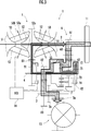
図1から図6を参照して、本発明の実施形態の無段変速機1を説明する。本実施形態の無段変速機1は、駆動源たる内燃機関(エンジン等。図示省略。)の動力がフライホイール11を介して伝達される入力軸2と、入力軸2と平行に配置された出力部材たる出力軸3と、入力軸2と出力軸3に平行に配置された中間軸4と、トロイダル型無段変速機構5と、第1ギア列6と、遊星歯車機構7と、を備える。
トロイダル型無段変速機構5は、入力軸2と同心であって一体に回転する一対の入力側ディスク51と、入力側ディスク51の間であって入力軸2に対して対向させると共に同心且つ回転自在に配置された出力側ディスク52と、入力側ディスク51と出力側ディスク52との間に配置され、入力側ディスク51と出力側ディスク52との間で動力を伝達させるパワーローラ53とを備える。
パワーローラ53は、入力側ディスク51と出力側ディスク52との間で動力を伝達させるべく回転できるように回転軸53aを備えると共に、回転軸53aと直交し紙面垂直方向に延びる揺動軸53b(トラニオン)に対して揺動自在となっており、パワーローラ53を揺動軸53b周りで揺動させて傾斜角度を変化させることで、トロイダル型無段変速機構5の変速比を変化できるように構成されている。本実施形態においては、揺動軸53b(トラニオン)が本発明のパワーローラの傾斜角度を調節自在な角度調整機構に相当する。
出力側ディスク52の外周には、第2駆動ギア52aが設けられている。この第2駆動ギア52aには、中間軸4に一体回転するように固定された第2従動ギア81が噛合している。本実施形態においては、この第2従動ギア81と第2駆動ギア52aとで本実施形態の第2ギア列を構成する。
遊星歯車機構7は、中間軸4に回転自在に軸支されたサンギア71と、リングギア72と、サンギア71及びリングギア72に噛合するピニオン73を自転及び公転自在に軸支するキャリア74との3つの要素を備える。この3つの要素は、各要素の相対回転速度の比を直線で表すことができる共線図において、サンギア71側から、夫々、第1要素、第2要素、第3要素とすると、第1要素はサンギア71、第2要素はキャリア74、第3要素はリングギア72となる。
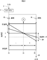
遊星歯車機構7のギア比(リングギア72の歯数/サンギア71の歯数)をiとすると、共線図(図4及び図6参照)において、サンギア71とキャリア74との間の間隔と、キャリア74とリングギア72との間の間隔との比は、i:1に設定される。なお、共線図とは、図4及び図6の中央部分に示すように、サンギア71とキャリア74とリングギア72との相対回転速度の比を直線で表すことができる図であり、「1」はトロイダル型無段変速機構5の最大変速比iの場合における出力側ディスク52の回転速度を示している。
第1ギア列6は、入力軸2に固定された第1駆動ギア61と、中間軸4と同心であってキャリア74(第2要素)に連結された第1従動ギア62と、第1駆動ギア61と第1従動ギア62とに噛合し、図示省略した変速機ケースに回転自在に軸支された中間ギア63とで構成される。第1ギア列6のギア比は、トロイダル型無段変速機構5の最大変速比iのギア比と同一に設定している。従って、図4及び図6に示すように、キャリア74(第2要素)の回転速度は「1」に設定される。
なお、第1ギア列6のギア比は、トロイダル型無段変速機構5のトルクシフト特性による変速比の変動を考慮して、トロイダル型無段変速機構5の最大変速比iのギア比と異ならせて設定してもよく、例えば、第1ギア列6のギア比をトロイダル型無段変速機構5の最大変速比iのギア比よりもトルクシフト特性による変動分だけ大きくなるように設定してもよい。
中間軸4には、反転ギア82が回転自在に軸支されている。また、無段変速機1には、高速側クラッチ91と、低速側クラッチ92とが設けられている。高速側クラッチ91は、反転ギア82と第2従動ギア81とを連結する連結状態と、この連結を断つ開放状態とに切換自在に構成されている。
低速側クラッチ92は、サンギア71(第1要素)と中間軸4とを連結する連結状態と、この連結を断つ開放状態とに切換自在に構成されている。高速側クラッチ91及び低速側クラッチ92は湿式多板クラッチで構成されている。
図2に示すように、低速側クラッチ92は、サンギア71(第1要素)と連結されるクラッチハブC1と、中間軸4とスプライン結合により連結されるクラッチドラムC2と、クラッチドラムC2の内周面にスプライン結合し軸方向に摺動自在な複数の外側プレートC2aと、この外側プレートC2aの間に配置され、クラッチハブC1の外周面にスプライン結合し軸方向に摺動自在な内側プレートC1aと、外側プレートC2aを軸方向に押圧可能なピストンC3と、ピストンC3とクラッチドラムC2との間で画成される油圧室C3aとを備える。
中間軸4内には、軸方向に延び、作動油が供給される油路4aが設けられている。また、中間軸4及びクラッチドラムC2には、油圧室C3aに作動油を供給するための油孔C4a,C4bが穿設されている。中間軸4とクラッチドラムC2との間には、油孔C4a,C4bから油圧室C3aに供給される作動油の漏れを防止すべくゴム製OリングC5が設けられている。
反転ギア82は、出力軸3に固定された伝達ギア83と噛合している。出力軸3には、デファレンシャルギア13と噛合する出力ギア3aが固定されている。また、出力ギア3aと伝達ギア83との間に位置させてパーキングギア3bが出力軸3に固定されている。
本実施形態の無段変速機1は、図3及び図4に示す低速走行用及び後進用の低速モードと、図5及び図6に示す高速走行用の高速モードとを備える。図3及び図4を参照して、低速モードは、トロイダル型無段変速機構5の速度比と無段変速機1の速度比が反比例の関係となる状態である。また、図3に示すように、低速モードにおいては、駆動力の一部がトロイダル型無段変速機構5を介して戻されて動力が循環する状態となる。図5及び図6を参照して、高速モードは、トロイダル型無段変速機構5の速度比と無段変速機1の速度比とが比例の関係となる状態である。
低速モードと高速モードとは、高速側クラッチ91及び低速側クラッチ92で切り換えられる。低速モードは、高速側クラッチ91を開放状態とし、低速側クラッチ92を連結状態とすることにより確立される。高速モードは、高速側クラッチ91を連結状態とし、低速側クラッチ92を開放状態とすることにより確立される。
図6に示すように、高速モードでも、キャリア74は第1ギア列6を介して回転速度「1」で回転する。しかしながら、高速モードでは、低速側クラッチ92が開放状態となるため、サンギア71(第1要素)が空転する状態となり、遊星歯車機構7には動力が伝達されない。
無段変速機1の制御部14は、CPU、メモリ等により構成された電子ユニット(ECU)であり、現在のモードやエンジン回転数、車両の走行速度等の所定の車両情報に基づき、トロイダル型無段変速機構5、高速側クラッチ91及び低速側クラッチ92を制御する。
本実施形態の無段変速機1によれば、低速側クラッチ92が、第1要素たるサンギア71と第2従動ギア81とを中間軸4を介して一体回転するように連結する連結状態と、この連結を断つ開放状態とに切換自在に構成されている。このため、低速側クラッチ92の容量を、サンギア71(第1要素)、キャリア74(第2要素)及びリングギア72(第3要素)の3つの要素のうちで通過トルクが最も小さい第1要素たるサンギア71と第2従動ギア81との連結に必要十分な容量に設定することができる。従って、従来のように、低速側クラッチを第3要素たるリングギアと中間軸とを連結自在に構成するものと比較して、低速側クラッチ92の容量を小さくすることができ、無段変速機1の小型化及び軽量化を図ることができる。
また、第2従動ギア81と連結する中間軸4に低速側クラッチ92のクラッチドラムC2が固定されているため、従来のようにクラッチドラムC2と中間軸4とが相対回転自在に設けられている場合と比較して、低速側クラッチ92のクラッチドラムC2のセンタリングを高精度で行うことができる。従って、クラッチドラムC2とピストンC3との間で画成される油圧室C3aの精度を向上させて、低速側クラッチ92の高精度化を図ることができる。
また、低速側クラッチ92のクラッチドラムC2が中間軸4に固定されているため、クラッチドラムC2と中間軸4との間で差回転が発生しない。従って、中間軸4と低速側クラッチ92のクラッチドラムC2との間に設けられたシール部材(ゴムリング)としてのゴム製OリングC5によるフリクションは発生せず、従来のようにクラッチドラムC2と中間軸4との間で差回転が発生するものと比較して、無段変速機1の伝達効率を向上させることができる。
また、低速側クラッチ92のクラッチドラムC2と中間軸4との間で差回転が生じないため、本実施形態のシール部材として、金属リングや樹脂リングと比較してシール性の高いゴム製OリングC5を設けることができる。従って、変速比が無限大となるギアードニュートラル及びその近傍などの精密な制御が必要な領域においても、低速側クラッチ92の正確な油圧制御が可能となる。
また、もともと比較的大径の出力側ディスク52を有効活用して、出力側ディスク52の外周に第2駆動ギア52aを構成している。従って、従来のように中間ギアを第2駆動ギアと第2従動ギアとに噛合させる場合に比し、第1駆動ギア61を大径とすることなく、コンパクトで軽量な無段変速機1を構成することができる。
なお、本実施形態では、駆動源として内燃機関を説明したが、本発明の駆動源はこれに限らず、例えば、モータ・ジェネレータ等の電動機を用いてもよい。
1…無段変速機、11…フライホイール、13…デファレンシャルギア、14…制御部、2…入力軸、3…出力軸、3a…出力ギア、3b…パーキングギア、4…中間軸、4a…油路、5…トロイダル型無段変速機構、51…入力側ディスク、52…出力側ディスク、52a…第2駆動ギア、53…パワーローラ、53a…回転軸、53b…揺動軸(トラニオン)、6…第1ギア列、61…第1駆動ギア、62…第1従動ギア、63…中間ギア、7…遊星歯車機構、71…サンギア(第1要素)、72…リングギア(第3要素)、73…ピニオン、74…キャリア(第2要素)、81…第2従動ギア、82…反転ギア、83…伝達ギア、91…高速側クラッチ、92…低速側クラッチ、C1…クラッチハブ、C1a…内側プレート、C2…クラッチドラム、C2a…外側プレート、C3…ピストン、C3a…油圧室、C4a,C4b…油孔、C5…ゴム製Oリング(ゴムリング、シール部材)。
Claims (6)
- 駆動源の動力が伝達される入力軸と、
前記入力軸と平行に配置された中間軸と、
該中間軸と同心に配置された反転ギアと、
前記入力軸と一体に回転する第1駆動ギア、及び、前記中間軸と同心に配置され、前記第1駆動ギアの動力が伝達される第1従動ギアを有する第1ギア列と、
前記入力軸と同心に配置される第2駆動ギア、及び、前記中間軸と同心に配置され、前記第2駆動ギアの動力が伝達される第2従動ギアを有する第2ギア列と、
前記第1ギア列と前記第2ギア列の一方の駆動ギア及び従動ギアに噛合する中間ギアと、
前記入力軸上に設けられたトロイダル型無段変速機構と、
前記中間軸上に設けられた遊星歯車機構と、
前記中間軸上に設けられた低速側クラッチと、高速側クラッチと、
前記トロイダル型無段変速機構、前記低速側クラッチ及び前記高速側クラッチを制御する制御部とを備え、
前記トロイダル型無段変速機構は、前記入力軸と一体に回転する入力側ディスクと、該入力側ディスクに対向して配置され、前記入力軸に対して相対回転自在な出力側ディスクと、前記入力側ディスクと前記出力側ディスクとの間で動力伝達可能に配置されたパワーローラと、該パワーローラの傾斜角度を調節自在な角度調整機構とを備え、該角度調整機構で前記パワーローラの傾斜角度を変更させて変速比を変更するものであり、
前記第2駆動ギアは、前記出力側ディスクと一体に回転し、
前記遊星歯車機構は、サンギア、キャリア及びリングギアからなる3つの要素を備え、
前記遊星歯車機構の3つの要素を、相対回転速度比を直線で表すことができる共線図におけるギア比に対応する間隔での並び順に前記サンギア側から夫々第1要素、第2要素及び第3要素として、
前記第2要素と前記第1従動ギアとが一体回転するように連結され、
前記第3要素と前記反転ギアとが一体回転するように連結され、
前記低速側クラッチは、前記第1要素と前記第2従動ギアとを一体回転するように連結する連結状態と、この連結を断つ開放状態とに切換自在に構成され、
前記高速側クラッチは、前記第2従動ギアと前記反転ギアとを一体回転するように連結する連結状態と、この連結を断つ開放状態とに切換自在に構成され、
前記制御部は、
前記低速側クラッチを連結状態とし、前記高速側クラッチを開放状態とすることで低速モードを実行し、
前記低速側クラッチを開放状態とし、前記高速側クラッチを連結状態とすることで高速モードを実行することを特徴とする無段変速機。 - 請求項1記載の無段変速機であって、
前記低速側クラッチは、クラッチハブと、クラッチドラムと、ピストンと、前記クラッチドラムと前記ピストンとで画成される油圧室とを備え、
前記低速側クラッチのクラッチドラムは前記中間軸に固定され、前記低速側クラッチのクラッチハブは前記第1要素に連結されることを特徴とする無段変速機。 - 請求項2記載の無段変速機であって、
前記中間軸内に設けられた作動油が供給される油路と、
前記油路と前記低速側クラッチの油圧室とを連通させるべく前記中間軸と前記クラッチドラムとに穿設された油孔と、
前記中間軸と前記クラッチハブとの間で前記油孔から前記油圧室に供給される作動油の漏れを防ぐシール部材とを備えることを特徴とする無段変速機。 - 請求項3記載の無段変速機であって、
前記シール部材はゴムリングであることを特徴とする無段変速機。 - 請求項4に記載の無段変速機であって、
前記第2駆動ギアは、前記出力側ディスクの外周に設けられ、
前記中間ギアは、前記第1駆動ギアと前記第1従動ギアとに噛合することを特徴とする無段変速機。 - 請求項1に記載の無段変速機であって、
前記第2駆動ギアは、前記出力側ディスクの外周に設けられ、
前記中間ギアは、前記第1駆動ギアと前記第1従動ギアとに噛合することを特徴とする無段変速機。
Applications Claiming Priority (2)
| Application Number | Priority Date | Filing Date | Title |
|---|---|---|---|
| JP2012-158991 | 2012-07-17 | ||
| JP2012158991 | 2012-07-17 |
Publications (1)
| Publication Number | Publication Date |
|---|---|
| WO2014013786A1 true WO2014013786A1 (ja) | 2014-01-23 |
Family
ID=49948622
Family Applications (1)
| Application Number | Title | Priority Date | Filing Date |
|---|---|---|---|
| PCT/JP2013/063785 Ceased WO2014013786A1 (ja) | 2012-07-17 | 2013-05-17 | 無段変速機 |
Country Status (1)
| Country | Link |
|---|---|
| WO (1) | WO2014013786A1 (ja) |
Cited By (2)
| Publication number | Priority date | Publication date | Assignee | Title |
|---|---|---|---|---|
| JP2016028205A (ja) * | 2014-07-08 | 2016-02-25 | 本田技研工業株式会社 | 車両用無段変速機 |
| CN107013636A (zh) * | 2016-01-28 | 2017-08-04 | 铃木株式会社 | 无级变速装置 |
Citations (4)
| Publication number | Priority date | Publication date | Assignee | Title |
|---|---|---|---|---|
| JPH04219557A (ja) * | 1990-12-18 | 1992-08-10 | Mazda Motor Corp | 無段変速機 |
| JP2000120833A (ja) * | 1998-10-16 | 2000-04-28 | Nissan Motor Co Ltd | 変速比無限大無段変速機 |
| JP2000193077A (ja) * | 1998-12-25 | 2000-07-14 | Nissan Motor Co Ltd | 変速比無限大無段変速機の変速制御装置 |
| JP2001263449A (ja) * | 2000-03-23 | 2001-09-26 | Mazda Motor Corp | トロイダル型無段変速機構造 |
-
2013
- 2013-05-17 WO PCT/JP2013/063785 patent/WO2014013786A1/ja not_active Ceased
Patent Citations (4)
| Publication number | Priority date | Publication date | Assignee | Title |
|---|---|---|---|---|
| JPH04219557A (ja) * | 1990-12-18 | 1992-08-10 | Mazda Motor Corp | 無段変速機 |
| JP2000120833A (ja) * | 1998-10-16 | 2000-04-28 | Nissan Motor Co Ltd | 変速比無限大無段変速機 |
| JP2000193077A (ja) * | 1998-12-25 | 2000-07-14 | Nissan Motor Co Ltd | 変速比無限大無段変速機の変速制御装置 |
| JP2001263449A (ja) * | 2000-03-23 | 2001-09-26 | Mazda Motor Corp | トロイダル型無段変速機構造 |
Cited By (2)
| Publication number | Priority date | Publication date | Assignee | Title |
|---|---|---|---|---|
| JP2016028205A (ja) * | 2014-07-08 | 2016-02-25 | 本田技研工業株式会社 | 車両用無段変速機 |
| CN107013636A (zh) * | 2016-01-28 | 2017-08-04 | 铃木株式会社 | 无级变速装置 |
Similar Documents
| Publication | Publication Date | Title |
|---|---|---|
| JP3896958B2 (ja) | 無段変速装置 | |
| CN102575753B (zh) | 连续可变比变速器 | |
| AU2011329525B2 (en) | Input clutch assembly for infinitely variable transmission | |
| JP5800088B2 (ja) | 車両用動力伝達装置 | |
| CN101818796A (zh) | 带有偏移输出轴的无级变速传动装置 | |
| JP2004176832A (ja) | 無段変速装置 | |
| WO2021073184A1 (zh) | 无动力中断的两挡变速电桥驱动系统 | |
| CN103133613A (zh) | 双模式无级变速器 | |
| WO2018163948A1 (ja) | ハイブリッド車両用トランスミッション | |
| JP2004232776A (ja) | トロイダル無段変速機 | |
| JP4151300B2 (ja) | 無段変速装置 | |
| WO2019129208A1 (zh) | 变速器、动力驱动系统及车辆 | |
| JP2015017664A (ja) | 電気自動車用駆動装置 | |
| WO2014013786A1 (ja) | 無段変速機 | |
| US7232396B2 (en) | Cone ring transmission | |
| JP6053820B2 (ja) | 無段変速機 | |
| JP5061647B2 (ja) | 無段変速装置 | |
| JP2006308039A (ja) | 無段変速装置 | |
| WO2019129202A1 (zh) | 变速器、动力驱动系统及车辆 | |
| WO2013046362A1 (ja) | 無段変速機 | |
| CN114635949A (zh) | 换挡结构及汽车 | |
| JP6296937B2 (ja) | 動力分割式無段変速機 | |
| JP5963227B2 (ja) | 無段変速機 | |
| JP2003314661A (ja) | 無段変速装置 | |
| CN110949105A (zh) | 两挡变速的电桥驱动系统和车辆 |
Legal Events
| Date | Code | Title | Description |
|---|---|---|---|
| 121 | Ep: the epo has been informed by wipo that ep was designated in this application |
Ref document number: 13820541 Country of ref document: EP Kind code of ref document: A1 |
|
| NENP | Non-entry into the national phase |
Ref country code: DE |
|
| 122 | Ep: pct application non-entry in european phase |
Ref document number: 13820541 Country of ref document: EP Kind code of ref document: A1 |
|
| NENP | Non-entry into the national phase |
Ref country code: JP |