WO2014013735A1 - 超音波探触子 - Google Patents
超音波探触子 Download PDFInfo
- Publication number
- WO2014013735A1 WO2014013735A1 PCT/JP2013/004374 JP2013004374W WO2014013735A1 WO 2014013735 A1 WO2014013735 A1 WO 2014013735A1 JP 2013004374 W JP2013004374 W JP 2013004374W WO 2014013735 A1 WO2014013735 A1 WO 2014013735A1
- Authority
- WO
- WIPO (PCT)
- Prior art keywords
- layer
- acoustic matching
- acoustic
- ultrasonic probe
- layers
- Prior art date
- Legal status (The legal status is an assumption and is not a legal conclusion. Google has not performed a legal analysis and makes no representation as to the accuracy of the status listed.)
- Ceased
Links
Images





Classifications
-
- B—PERFORMING OPERATIONS; TRANSPORTING
- B06—GENERATING OR TRANSMITTING MECHANICAL VIBRATIONS IN GENERAL
- B06B—METHODS OR APPARATUS FOR GENERATING OR TRANSMITTING MECHANICAL VIBRATIONS OF INFRASONIC, SONIC, OR ULTRASONIC FREQUENCY, e.g. FOR PERFORMING MECHANICAL WORK IN GENERAL
- B06B1/00—Methods or apparatus for generating mechanical vibrations of infrasonic, sonic, or ultrasonic frequency
- B06B1/02—Methods or apparatus for generating mechanical vibrations of infrasonic, sonic, or ultrasonic frequency making use of electrical energy
- B06B1/06—Methods or apparatus for generating mechanical vibrations of infrasonic, sonic, or ultrasonic frequency making use of electrical energy operating with piezoelectric effect or with electrostriction
- B06B1/0644—Methods or apparatus for generating mechanical vibrations of infrasonic, sonic, or ultrasonic frequency making use of electrical energy operating with piezoelectric effect or with electrostriction using a single piezoelectric element
- B06B1/0662—Methods or apparatus for generating mechanical vibrations of infrasonic, sonic, or ultrasonic frequency making use of electrical energy operating with piezoelectric effect or with electrostriction using a single piezoelectric element with an electrode on the sensitive surface
- B06B1/067—Methods or apparatus for generating mechanical vibrations of infrasonic, sonic, or ultrasonic frequency making use of electrical energy operating with piezoelectric effect or with electrostriction using a single piezoelectric element with an electrode on the sensitive surface which is used as, or combined with, an impedance matching layer
-
- A—HUMAN NECESSITIES
- A61—MEDICAL OR VETERINARY SCIENCE; HYGIENE
- A61B—DIAGNOSIS; SURGERY; IDENTIFICATION
- A61B8/00—Diagnosis using ultrasonic, sonic or infrasonic waves
- A61B8/44—Constructional features of the ultrasonic, sonic or infrasonic diagnostic device
- A61B8/4483—Constructional features of the ultrasonic, sonic or infrasonic diagnostic device characterised by features of the ultrasound transducer
- A61B8/4494—Constructional features of the ultrasonic, sonic or infrasonic diagnostic device characterised by features of the ultrasound transducer characterised by the arrangement of the transducer elements
-
- G—PHYSICS
- G10—MUSICAL INSTRUMENTS; ACOUSTICS
- G10K—SOUND-PRODUCING DEVICES; METHODS OR DEVICES FOR PROTECTING AGAINST, OR FOR DAMPING, NOISE OR OTHER ACOUSTIC WAVES IN GENERAL; ACOUSTICS NOT OTHERWISE PROVIDED FOR
- G10K11/00—Methods or devices for transmitting, conducting or directing sound in general; Methods or devices for protecting against, or for damping, noise or other acoustic waves in general
- G10K11/02—Mechanical acoustic impedances; Impedance matching, e.g. by horns; Acoustic resonators
Definitions
- the present invention relates to an ultrasonic probe used for obtaining an ultrasonic image of a subject by applying ultrasonic waves to a subject such as a living body.
- the ultrasonic diagnostic apparatus applies information to a living subject such as a human being or an animal, and displays a tomographic image of the in vivo tissue based on the reflected signal on the monitor, thereby providing information necessary for the diagnosis of the subject. I will provide a.
- the user of the ultrasonic diagnostic apparatus uses an ultrasonic probe including a sensor that transmits an ultrasonic signal to the subject and receives an ultrasonic signal that is a reflected signal in the subject.
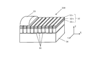
- FIG. 10 is a schematic perspective view showing an example of an ultrasonic probe.
- An ultrasonic probe 100 shown in FIG. 10 includes a plurality of piezoelectric elements 11 arranged to transmit and receive ultrasonic signals to and from a subject (not shown), and a front surface of the piezoelectric elements 11 on the subject side.
- the lens 13 and the back surface load material 14 provided in the back surface on the opposite side to the acoustic matching layer 12 of the piezoelectric element 11 are provided.
- Electrodes (not shown) are arranged on the front and back surfaces of the piezoelectric element 11, respectively.
- An ultrasonic wave is generated by applying a voltage to the electrode and vibrating the piezoelectric element 11.
- the piezoelectric element 11 is formed of a piezoelectric ceramic such as a PZT system, a single crystal such as PMN-PT, a composite piezoelectric material in which the material is combined with a polymer, a polymer piezoelectric material represented by PVDF, or the like. .
- the piezoelectric element 11 converts the voltage into an ultrasonic wave and transmits it to the subject, receives the ultrasonic wave reflected in the subject and converts it into an electrical signal.
- a plurality of piezoelectric elements 11 are arranged in the X-axis direction.
- Such a plurality of arrangements of the piezoelectric elements 11 is a so-called “electronic scanning type” in which ultrasonic waves are electronically scanned.
- This type of ultrasonic probe can deflect or focus an ultrasonic beam by phase control, and further electronically sequentially switch and scan a plurality of piezoelectric elements 11 to image an ultrasonic tomography in real time. To do.
- an ultrasonic probe of a type in which a single piezoelectric element is mechanically scanned to image an ultrasonic tomography with almost no time difference.
- the acoustic lens 13 plays a role of narrowing the ultrasonic beam in order to increase the resolution of the diagnostic image.
- the acoustic lens 13 extends along the Y direction (direction orthogonal to the arrangement direction X of the piezoelectric elements 11) shown in FIG. 10 and is formed in a smooth convex shape in the Z direction.
- the sound beam can be narrowed in the Y direction.
- the acoustic lens 13 is an optional element and is provided as necessary.
- the back load material 14 is coupled to and holds the piezoelectric element 11 and further attenuates unnecessary ultrasonic waves.
- the back load material 14 is also an optional element and is provided as necessary.
- the acoustic matching layer 12 is provided to prevent a reduction in sensitivity and resolution caused by the mismatch because the difference in acoustic impedance between the piezoelectric element 11 and the subject is large. In recent years, in order to achieve further higher resolution, studies have been made to increase the frequency bandwidth. As one of the methods, it can be considered that the acoustic matching layer provided on the subject side of the piezoelectric element is multi-layered into three or more layers (for example, refer to Patent Documents 1 and 2).
- the material of the layer on the subject side of the multilayered acoustic matching layer is a thermosetting material produced by bridging polystyrene with divinylbenzene having an acoustic impedance of 2.44 megarails as shown in Patent Document 1.
- LDPE low density polyethylene
- the X-axis direction shown in FIG. 10 is the “(piezoelectric element) arrangement direction”
- the Y-axis direction is the “(piezoelectric element) width direction”
- the Z-axis direction is “(piezoelectric element)”. ) "Thickness direction”.
- the acoustic matching layer has a multi-layered structure, not only the frequency characteristics are broadened, but also the frequency characteristics vary greatly depending on how the acoustic impedance value of the acoustic matching layer provided on the subject side is selected. Since the frequency characteristic greatly affects the resolution of the ultrasonic image, it is important how to select the acoustic impedance value of each layer of the acoustic matching layer and use a material that matches the selected value.
- thermosetting material generated by cross-linked polystyrene with divinylbenzene is used as the material of the object side layer of the multilayered acoustic matching layer. Since the acoustic impedance of the layer provided on the subject side is large, the low frequency range is high, the frequency characteristics are rippled, and the pulse length is long. For this reason, even if the bandwidth can be increased, the resolution is remarkably reduced from a shallow region to a subject having frequency-dependent attenuation. Furthermore, the resolution decreases as the depth increases, making it difficult to obtain a high-resolution image.
- An object of the present invention is to provide a high-quality ultrasonic probe capable of obtaining a high-resolution ultrasonic image.
- the present invention includes a piezoelectric element having a first surface and a second surface, a first electrode connected to the first surface, a second electrode connected to the second surface, And an acoustic probe having a configuration in which a mixture of a resin and an elastomer is used for at least a part of the acoustic matching layer.
- the acoustic matching layer may be composed of a plurality of layers, and at least a part of the acoustic matching layer may be a layer that is present at a position farthest from the piezoelectric element among the plurality of layers. Good.
- the present invention may be characterized in that only a layer that is present at a position farthest from the piezoelectric element among the plurality of layers is a layer in which a mixture is used.
- the present invention may be characterized in that the resin is styrene or a styrene-methyl methacrylate copolymer.
- the present invention may be characterized in that the elastomer is synthetic rubber or natural rubber.
- the present invention may be characterized in that the synthetic rubber is butadiene.
- the present invention may be characterized in that the acoustic matching layer is composed of a plurality of layers, and each acoustic impedance of the plurality of layers gradually decreases from a layer closer to the piezoelectric element to a layer farther away.
- the present invention may be characterized in that the acoustic matching layer is composed of three layers.
- At least a part of the acoustic matching layer is a layer that is present at a position farthest from the piezoelectric element among the three layers, and the acoustic impedance of at least a part of the acoustic matching layer is 1.9 to The value may be in the range of 2.3 megarails.
- the acoustic matching layer is a layer that is present at a position farthest from the piezoelectric element among the three layers, the resin is styrene, the elastomer is butadiene, and is mixed with styrene.
- the blending weight ratio of butadiene may be in the range of 3 to 29%.
- the present invention may be characterized in that the acoustic matching layer is composed of four layers.
- At least a part of the acoustic matching layers is a layer that is present at a position farthest from the piezoelectric element among the four layers, and an acoustic impedance of at least a part of the acoustic matching layers is 1.8 to The value may be in the range of 2.28 megarails.
- the acoustic matching layer is a layer that is present at a position farthest from the piezoelectric element among the four layers, the resin is styrene, the elastomer is butadiene, and is mixed with styrene.
- the blending weight ratio of butadiene may be in the range of 4 to 40%.
- the present invention may be characterized in that the acoustic matching layer is composed of five layers.
- At least a part of the acoustic matching layers is a layer that is present at a position farthest from the piezoelectric element among the five layers, and an acoustic impedance of at least a part of the acoustic matching layers is 1.6 to The value may be in the range of 1.8 megarails.
- the acoustic matching layer is a layer that is present at a position farthest from the piezoelectric element among the five layers, the resin is styrene, the elastomer is butadiene, and is mixed with styrene.
- the blending weight ratio of butadiene may be in the range of 40 to 68%.
- the present invention may be characterized in that the conductive foil electrically connected to the first electrode is formed between the piezoelectric element and the acoustic matching layer.
- the frequency characteristics and pulse having a wide band and a smooth shape are used.
- a characteristic having a short length can be obtained.
- 1 is a schematic sectional view showing an ultrasonic probe according to a first embodiment of the present invention.
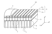
- 1 is a schematic perspective view showing an ultrasonic probe according to a first embodiment of the present invention.
- the figure which shows the relationship between the acoustic impedance of a 3rd acoustic matching layer, a frequency ratio band, and a pulse length.
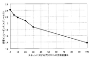
- Diagram showing the relationship between the weight ratio of butadiene to styrene and acoustic impedance
- Schematic perspective view showing an ultrasonic probe according to a second embodiment of the present invention The figure which shows the relationship between the acoustic impedance of a 4th acoustic matching layer, a frequency ratio band, and a pulse length.
- FIG. 1 Schematic perspective view showing an ultrasonic probe according to a third embodiment of the present invention.
- FIG. 1 is a schematic cross-sectional view showing the ultrasonic probe of the first embodiment.
- FIG. 2 is a schematic perspective view showing the ultrasonic probe of the first embodiment.
- the ultrasonic probe can be used by being electrically connected to the main body of the ultrasonic diagnostic apparatus via a cable when configuring the ultrasonic diagnostic apparatus.
- the ultrasonic probe transmits and receives ultrasonic waves, converts the received waves into electric signals, and transmits them to the main body of the ultrasonic diagnostic apparatus.
- An image is generated by the signal processing unit in the ultrasonic diagnostic apparatus, and the image is displayed on the display unit.
- An ultrasonic probe 10 shown in FIG. 1 includes a piezoelectric element 1, a ground electrode 5, a signal electrode 6, a signal electrical terminal 7, a back load material 3, an acoustic matching layer 2, and an acoustic lens 4. Is provided.
- the piezoelectric element 1 is formed of a piezoelectric ceramic such as a PZT system, a piezoelectric single crystal such as a PZN-PT or PMN-PT system, or a composite piezoelectric body in which the material is combined with a polymer, and transmits / receives ultrasonic waves.
- the ground electrode 5 is provided on one surface of the piezoelectric element 1 by evaporating or sputtering gold or silver, or by baking silver. The ground electrode 5 is electrically connected to the one surface of the piezoelectric element 1.
- the signal electrode 6 is opposite to the one surface of the piezoelectric element 1 provided with the ground electrode 5 by vapor deposition or sputtering of gold or silver, or by baking of silver. Provided on one side.
- the signal electrode 6 is electrically connected to the other surface of the piezoelectric element 1.
- the signal electrical terminal 7 is electrically connected to the signal electrode 6.
- the back load material 3 physically holds the piezoelectric element 1 and attenuates unnecessary ultrasonic signals as necessary.
- the acoustic matching layer 2 is provided on the ground electrode 5 of the piezoelectric element 1.
- the acoustic matching layer 2 is composed of three layers (in FIG. 1, 2a, 2b, and 2c from the piezoelectric element 1 side, respectively).
- each layer constituting the acoustic matching layer 2 is referred to as an “acoustic matching divided layer”.
- the first acoustic matching division layer 2a, the second acoustic matching division layer 2b, and the third acoustic matching division layer 2c are laminated in this order from the piezoelectric element 1 side to the subject side. Yes.
- the acoustic lens 4 is an optional element and is disposed on the acoustic matching layer 2. Further, in the example shown in FIG. 1, the piezoelectric element 1 and the acoustic matching layer 2 are individually divided, and the divided groove portions are made of silicone rubber or urethane rubber having a small acoustic coupling. The material is filled.
- the piezoelectric element 1 When a voltage is applied to the ground electrode 5 and the signal electrode 6 from the main body of an ultrasonic diagnostic apparatus (not shown) to which the ultrasonic probe 10 is connected, the piezoelectric element 1 mechanically vibrates and generates ultrasonic waves. .
- the ultrasonic waves generated by the piezoelectric element 1 propagate through the acoustic matching layer 2 and are transmitted to the subject.
- the piezoelectric element 1 receives a reflected wave from the subject.
- An ultrasound probe of an ultrasound diagnostic apparatus that uses a living body as a subject is a reflection that is directly contacted with the living body or indirectly through an ultrasound propagation medium, and transmits ultrasonic waves to the living body and is reflected from the living body. It is a so-called sensor that receives waves again.
- the signal received by the ultrasonic probe is processed by the main body of the ultrasonic diagnostic apparatus, and the image displayed on the monitor is used for diagnosis and the like.
- a material having an acoustic impedance in the range of 8 to 20 megarails is used.
- the material include glass such as silicon, quartz, and fused quartz, free-cutting ceramics, or graphite filled with metal powder.
- a material having an acoustic impedance in the range of 3 to 8 megarails is used for the second acoustic matching division layer 2b.
- the material is, for example, graphite or an epoxy resin in which an epoxy resin is filled with a filler such as a metal or an oxide.
- the third acoustic matching divided layer 2c provided at the position farthest from the piezoelectric element 1 in the acoustic matching layer 2 is a mixture of at least two kinds of materials including an elastomer material, for example, an elastomer material mixed with a resin material.
- an elastomer material for example, an elastomer material mixed with a resin material.
- the material is used and the acoustic impedance has a value in the range of 1.9 to 2.3 megarails.
- a mixture in which an elastomer material is mixed with a resin material includes a copolymer of the resin material and the elastomer.
- the acoustic impedance of each acoustic matching divided layer decreases in order from the layer close to the piezoelectric element 1 toward the layer close to the subject.
- the third acoustic matching division layer 2c is made of a mixture containing an elastomer material, it has high adhesiveness. Moreover, since the material of the 3rd acoustic matching division
- FIG. 3 is a diagram illustrating the relationship between the acoustic impedance of the third acoustic matching division layer 2c, the pulse length, and the frequency ratio band.
- the horizontal axis of the graph shown in FIG. 3 indicates the acoustic impedance (unit: megarails) of the third acoustic matching division layer 2c.
- the vertical axis on the left side of the graph represents the pulse length (unit: ⁇ s), and the vertical axis on the right side represents the frequency ratio band (bandwidth / center frequency) (unit: percent).
- the center frequency of the ultrasonic wave is set to 7.5 MHz
- the acoustic impedance of the back load material 3 is 7 megarails
- the piezoelectric element 1 is equivalent to PZT-5H with PZT-based piezoelectric ceramics.
- the first acoustic matching divided layer 2a is made of a free-cutting ceramic having an acoustic impedance of 13 megarails
- the second acoustic matching divided layer 2b is made of an epoxy resin filled with metal powder having an acoustic impedance of 4 megarails.
- the frequency ratio band and the pulse length were calculated in a configuration in which the acoustic impedance of the third acoustic matching divided layer 2c located closest to the subject was varied in the range of 1.6 to 2.6 megarails.
- Each thickness of the first to third acoustic matching division layers 2a, 2b, and 2c was set to 0.25 wavelength.
- the frequency ratio band is indicated by a solid line with a value of ⁇ 6 dB
- the pulse length is indicated with a broken line at values of ⁇ 6 dB, ⁇ 20 dB, and ⁇ 40 dB.
- the pulse length value is relatively large when the acoustic impedance is less than 1.9 megarails and greater than 2.3 megarails.
- the pulse length value becomes relatively large when the acoustic impedance becomes a value smaller than 1.7 megarails. The smaller the pulse length, the higher the resolution and the better. Therefore, it is important to reduce the pulse length to improve the resolution.
- the frequency ratio band is desirably 90% or more.
- the frequency ratio band is 90% or more when the acoustic impedance of the third acoustic matching division layer 2c is 1.75 megarails or more and 2.4 megarails or less.
- the frequency ratio band is large and the pulse length is short. This indicates that the shape of the frequency characteristic of the ultrasonic wave is smooth and close to the shape of a normal distribution.
- the acoustic impedance of the third acoustic matching division layer 2c is preferably in the range of 1.9 megarails or more and 2.3 megarails or less. .
- FIG. 4 is a graph showing the relationship between the weight ratio of butadiene to styrene and acoustic impedance.
- the horizontal axis of the graph shown in FIG. 4 shows the value of the mixed filling weight ratio (unit: percent) in which butadiene is blended with styrene. That is, a value of 0 on the horizontal axis indicates 100% styrene, and a value of 100 indicates 100% butadiene.
- shaft of the same graph shows acoustic impedance (a unit is Megarails).
- the acoustic impedance of 100% styrene (value of 0 on the horizontal axis) is 2.42 megarails
- the acoustic impedance of 100% butadiene (value of 100 on the horizontal axis) is 1.37. Megarails.
- the acoustic impedance of the mixture is 2.25 (sound speed is 2165 m / sec.) And 2.17 (sound speed is 2107 m / sec.), Respectively. ), 2.07 (sound speed is 2028 m / sec.), 1.87 (sound speed is 1853 m / sec.) Megarails.
- acoustic impedance shows the value computed from the density x sound speed by measuring the density and sound speed of the produced material at 25 degreeC.
- Weight of butadiene mixed with styrene when used for the third acoustic matching divided layer 2c which is in the range of 1.9 to 2.3 megarails, which is a preferable range of the acoustic impedance of the third acoustic matching divided layer 2c. Since the ratio is in the range of 3 to 29%, it is preferable to mix butadiene with styrene at a filling weight ratio in this range.
- a mixture of styrene and butadiene has the advantage that it can be easily formed into a film of any thickness in the same way as a method of forming a resin material into a film, and can be manufactured with extremely large amounts with high accuracy. Can be lowered. Moreover, since butadiene is mixed, the adhesiveness is better than that of styrene alone, and a high-quality ultrasonic probe can be obtained.
- the acoustic matching layer 2 having a three-layer structure as a material for the third acoustic matching divided layer 2c provided on the subject side, a mixture of styrene and butadiene mixed at an arbitrary filling weight ratio is used.
- a characteristic in which the frequency bandwidth is wide and the pulse length is short that is, the frequency characteristic of the ultrasonic wave is close to a normal distribution. For this reason, an ultrasonic probe capable of obtaining a high-resolution ultrasonic image can be realized.
- the case where the acoustic impedances of the first and second acoustic matching divided layers 2a and 2b are 13 megarails and 4 megarails, respectively.
- the acoustic impedance of the first acoustic matching division layer 2a varies in the range of 8 to 20 megarails
- the acoustic impedance of the second acoustic matching division layer 2b varies in the range of 3 to 8 megarails
- the respective combinations As for the acoustic impedance of the third acoustic matching division layer 2c an optimum value is calculated.
- the preferred acoustic impedance value of the third acoustic matching division layer 2c does not deviate significantly from the range of 1.9 to 2.3 megarails.
- the configuration shown in FIG. 2 in which the piezoelectric elements 1 are arranged one-dimensionally has been described.
- the present embodiment is applied to a two-dimensional array-type electronic scanning ultrasonic probe in which a plurality of the configurations are arranged.
- the same effect can be obtained.
- the three acoustic matching layers 2 corresponding to the piezoelectric element 1 are also divided into a plurality of pieces in the X-axis direction
- the first and second acoustic matching divided layers 2a and 2b are divided into the third
- the acoustic matching division layer 2c may be produced without being divided. Further, the same effect can be obtained even when applied to an ultrasonic probe of a single piezoelectric element.
- the resin material is preferably a synthetic resin. Synthetic resins can be broadly classified into thermoplastic resins and thermosetting resins. As the thermosetting resin material, for example, phenol resin, epoxy resin, or urethane resin can be used.
- the resin material is not limited to these resin materials as long as it is a material that can be mixed with the elastomer material in addition to the resin materials described above, but it is particularly preferable to use a thermoplastic material.
- the thermoplastic resin material When producing a mixture of a resin material and an elastomer, the thermoplastic resin material can be made into a mixture in which an elastomer or the like is uniformly dispersed by a uniaxial or biaxial kneading extruder, and this mixture is extruded. Can be molded. For this reason, the material of the uniform acoustic characteristic with few dispersion
- the present invention is not limited to this as long as it is an elastomer material that can create a mixture of a natural rubber or a synthetic rubber material with a resin material. . Note that it is more preferable to select an elastomer material having a small ultrasonic attenuation, such as butadiene. This is because the ultrasonic attenuation of the material when the mixture is made can be reduced.
- the acoustic matching layer is preferably made of a material having a small ultrasonic attenuation.
- the acoustic matching layer 2 having a three-layer structure has been described.
- the acoustic impedance of the piezoelectric element 1 is made of a material having a low acoustic impedance, for example, a composite piezoelectric body of PZT piezoelectric ceramic and epoxy resin, and the acoustic impedance is about 15 megarails or less.
- the acoustic matching layer 2 can be constituted by one layer or two layers, and a wide band can be realized.
- a layer made of a mixture of a resin material and an elastomer material may be used for one or two acoustic matching layers.
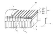
- FIG. 5 is a schematic perspective view showing the ultrasonic probe of the second embodiment.
- the ultrasonic probe 20 of the second embodiment shown in FIG. 5 has the same configuration except for the configuration of the acoustic matching layer 2 provided in the ultrasonic probe 10 of the first embodiment shown in FIG. 1 and FIG.
- Have The same components as those included in the ultrasound probe 10 of the first embodiment are denoted by the same reference numerals, and description thereof is omitted.
- the ultrasonic probe 20 includes the piezoelectric element 1, the ground electrode 5, the signal electrode 6, the signal electrical terminal 7, the back load material 3 and the acoustic lens 4, and the acoustic matching layer 202, similar to the first embodiment. .
- the piezoelectric element 1 and the acoustic matching layer 202 are individually divided, and a material such as silicone rubber or urethane rubber having a small acoustic coupling is formed in the divided groove portions. Filled.
- the acoustic matching layer 202 is provided on the ground electrode 5 of the piezoelectric element 1.
- the acoustic matching layer 202 is composed of four layers (202a, 202b, 202c, and 202d from the piezoelectric element 1 side in FIG. 5).
- Each layer constituting the acoustic matching layer 202 is referred to as an “acoustic matching division layer”.
- the first acoustic matching divided layer 202a, the second acoustic matching divided layer 202b, the third acoustic matching divided layer 202c, and the fourth acoustic matching are performed from the piezoelectric element 1 side to the subject side.
- the divided layers 202d are stacked in this order.
- a material having an acoustic impedance in the range of 15 to 25 megarails is used for the first acoustic matching division layer 202a.
- the material is, for example, silicon single crystal, quartz, glass such as fused quartz, or free-cutting ceramics.
- a material having an acoustic impedance in the range of 6 to 12 megarails is used for the second acoustic matching division layer 202b.
- the material is, for example, graphite or an epoxy resin in which an epoxy resin is filled with a filler such as a metal or an oxide.
- a material having an acoustic impedance in the range of 3 to 5 megarails is used for the third acoustic matching division layer 202c.
- the material is, for example, graphite, a resin material, or an epoxy resin in which an epoxy resin is filled with a filler such as a metal or an oxide.
- the fourth acoustic matching division layer 202d provided at the position farthest from the piezoelectric element 1 in the acoustic matching layer 202 is a mixture of at least two kinds of materials including an elastomer material, for example, an elastomer material mixed with a resin material.
- the material is used and the acoustic impedance has a value in the range of 1.8-2.28 megarails.
- a mixture in which an elastomer material is mixed with a resin material includes a copolymer of the resin material and the elastomer.
- the acoustic impedance of each acoustic matching divided layer decreases in order from the layer close to the piezoelectric element 1 toward the layer close to the subject.
- the fourth acoustic matching divided layer 202d is made of a mixture containing an elastomer material, and thus has high adhesiveness. Moreover, since the material of the 4th acoustic matching division
- FIG. 6 is a diagram illustrating the relationship between the acoustic impedance of the fourth acoustic matching division layer 202d, the pulse length, and the frequency ratio band.
- the horizontal axis of the graph shown in FIG. 6 indicates the acoustic impedance (unit: megarails) of the fourth acoustic matching division layer 202d.
- the vertical axis on the left side of the graph represents the pulse length (unit: ⁇ s), and the vertical axis on the right side represents the frequency ratio band (bandwidth / center frequency) (unit: percent).
- the center frequency of the ultrasonic wave is set to 7.5 MHz
- the acoustic impedance of the back load material 3 is 7 megarails
- the piezoelectric element 1 is PZT-based piezoelectric ceramics corresponding to PZT-5H.
- the first acoustic matching division layer 202a is made of a free-cutting ceramic having an acoustic impedance of 17 megarails
- the second acoustic matching division layer 202b is made of an epoxy resin filled with metal powder having an acoustic impedance of 8 megarails.
- the third acoustic matching divided layer 202c is made of epoxy resin filled with metal powder having an acoustic impedance of 3.8 megarails, and the acoustic impedance of the fourth acoustic matching divided layer 202d located closest to the subject is 1.
- Luth length was calculated.
- the thickness of the first acoustic matching division layer 202a was 0.27 wavelength
- the thickness of each of the second to fourth acoustic matching division layers 202b, 202c, 202d was 0.25 wavelength.
- the value of the frequency ratio band at ⁇ 6 dB is indicated by a solid line
- the pulse length is indicated by a broken line at values of ⁇ 6 dB, ⁇ 20 dB, and ⁇ 40 dB.
- the frequency ratio band is desirably 90% or more.
- the frequency ratio band is 90% or more when the acoustic impedance of the fourth acoustic matching division layer 202d is 1.6 megarails or more and 2.28 megarails or less.
- the frequency ratio band is more preferably 95% or more, and the acoustic impedance of the fourth acoustic matching division layer 202d in this case is 1.65 megarails or more and 2.07 megarails or less.
- the frequency ratio band is large and the pulse length is short. This indicates that the shape of the frequency characteristic of the ultrasonic wave is smooth and close to the shape of a normal distribution.
- the acoustic impedance of the fourth acoustic matching divided layer 202d is preferably in the range of 1.8 megarails to 2.28 megarails. Furthermore, the acoustic impedance of the fourth acoustic matching division layer 202d is more preferably in the range of 1.8 megarails to 2.07 megarails.
- the mixing ratio when a mixture of styrene which is a resin material and butadiene which is one of synthetic rubber materials is used as the material of the fourth acoustic matching divided layer 202d will be described with reference to FIG.
- Load weight of butadiene mixed with styrene when used for the fourth acoustic matching divided layer 202d which is in the range of 1.8 to 2.28 megarails, which is a preferable range of acoustic impedance of the fourth acoustic matching divided layer 202d. Since the ratio is in the range of 4 to 40%, it is preferable to mix butadiene with styrene at a filling weight ratio in this range. Further, it is more preferable if the filling weight ratio is in the range of 5 to 40%.
- a mixture of styrene and butadiene has the advantage that it can be easily formed into a film of any thickness in the same way as a method of forming a resin material into a film, and can be manufactured with extremely large amounts with high accuracy. Can be lowered. Moreover, since butadiene is mixed, the adhesiveness is better than that of styrene alone, and a high-quality ultrasonic probe can be obtained.
- the frequency of the four-layer structure shown in FIG. There is also a region where the ratio band is large and the frequency ratio band is 100% or more.
- the frequency bandwidth As described above, as the number of layers constituting the acoustic matching layer increases, it is possible to increase the frequency bandwidth, which tends to be a desirable characteristic for realizing high resolution.
- the acoustic matching layer 202 having a four-layer structure as a material of the fourth acoustic matching divided layer 202d provided on the subject side, a mixture of styrene and butadiene mixed at an arbitrary filling weight ratio is used.
- a characteristic in which the frequency bandwidth is wide and the pulse length is short that is, the frequency characteristic of the ultrasonic wave is close to a normal distribution. For this reason, an ultrasonic probe capable of obtaining a high-resolution ultrasonic image can be realized.
- the acoustic impedances of the first acoustic matching divided layer 202a, the second acoustic matching divided layer 202b, and the third acoustic matching divided layer 202c are 17 megarails, 8 megarails, and 3.8 megarails, respectively.
- the acoustic impedances of the first acoustic matching divided layer 202a, the second acoustic matching divided layer 202b, and the third acoustic matching divided layer 202c are 17 megarails, 8 megarails, and 3.8 megarails, respectively.
- the acoustic impedance of the first acoustic matching division layer 202a varies in the range of 15 to 25 megarails
- the acoustic impedance of the second acoustic matching division layer 202b varies in the range of 6 to 12 megarails
- the third acoustic matching division When the acoustic impedance of the layer 202c fluctuates in the range of 3 to 5 megarails, the optimum value of the acoustic impedance of the fourth acoustic matching division layer 202d is calculated for each combination.
- the preferred acoustic impedance value of the fourth acoustic matching splitting layer 202d does not deviate significantly from the range of 1.8-2.28 megarails.
- the configuration shown in FIG. 5 in which the piezoelectric elements 1 are arranged one-dimensionally has been described.
- the present embodiment is applied to a two-dimensional array-type electronic scanning ultrasonic probe in which a plurality of the configurations are arranged.
- the same effect can be obtained.
- the four acoustic matching layers 202 corresponding to the piezoelectric element 1 are also divided into a plurality of pieces in the X-axis direction, the first, second, and third acoustic matching divided layers 202a, 202b, and 202c are divided.
- the fourth acoustic matching divided layer 202d may be manufactured without being divided. Further, the same effect can be obtained even when applied to an ultrasonic probe of a single piezoelectric element.
- the resin material is preferably a synthetic resin. Synthetic resins can be broadly classified into thermoplastic resins and thermosetting resins. As the thermosetting resin material, for example, phenol resin, epoxy resin, or urethane resin can be used.
- the resin material is not limited to these resin materials as long as it is a material that can be mixed with the elastomer material in addition to the resin materials described above, but it is particularly preferable to use a thermoplastic material.
- the thermoplastic resin material When producing a mixture of a resin material and an elastomer, the thermoplastic resin material can be made into a mixture in which an elastomer or the like is uniformly dispersed by a uniaxial or biaxial kneading extruder, and this mixture is extruded. Can be molded. For this reason, the material of the uniform acoustic characteristic with few dispersion
- the present invention is not limited to this as long as it is an elastomer material that can create a mixture of a natural rubber or a synthetic rubber material with a resin material. . Note that it is more preferable to select an elastomer material having a small ultrasonic attenuation, such as butadiene. This is because the ultrasonic attenuation of the material when the mixture is made can be reduced.
- the acoustic matching layer is preferably made of a material having a small ultrasonic attenuation.
- the material of the fourth acoustic matching divided layer 202d it has been described that two kinds of mixtures of styrene and butadiene are used as the material of the fourth acoustic matching divided layer 202d.
- other materials such as fibrous materials when strength needs to be increased, and powders such as oxides are added when hardness is increased.
- the same effect can be obtained if the acoustic impedance in the above range can be obtained.
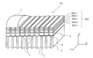
- FIG. 7 is a schematic perspective view showing the ultrasonic probe of the second embodiment.
- the ultrasonic probe 30 of the third embodiment shown in FIG. 7 has the same configuration except for the configuration of the acoustic matching layer 2 provided in the ultrasonic probe 10 of the first embodiment shown in FIG. 1 and FIG.
- Have The same components as those included in the ultrasound probe 10 of the first embodiment are denoted by the same reference numerals, and description thereof is omitted.
- the ultrasonic probe 30 includes the piezoelectric element 1, the ground electrode 5, the signal electrode 6, the signal electrical terminal 7, the back load material 3 and the acoustic lens 4, and the acoustic matching layer 302, similar to the first embodiment. .
- the piezoelectric element 1 and the acoustic matching layer 302 are divided individually, and a material such as silicone rubber or urethane rubber having a small acoustic coupling is formed in the divided groove portions. Filled.
- the acoustic matching layer 302 is provided on the ground electrode 5 of the piezoelectric element 1.
- the acoustic matching layer 302 includes five layers (302a, 302b, 302c, 302d, and 302e from the piezoelectric element 1 side in FIG. 7).
- Each layer constituting the acoustic matching layer 302 is referred to as an “acoustic matching division layer”.
- the first acoustic matching divided layer 302a, the second acoustic matching divided layer 302b, the third acoustic matching divided layer 302c, and the fourth acoustic matching are performed from the piezoelectric element 1 side to the subject side.
- the division layer 302d and the fifth acoustic matching division layer 302e are stacked in this order.
- a material having an acoustic impedance in the range of 15 to 25 megarails is used for the first acoustic matching division layer 302a.
- the material is, for example, silicon single crystal, quartz, glass such as fused quartz, or free-cutting ceramics.
- the second acoustic matching division layer 302b is made of a material having an acoustic impedance in the range of 8 to 14 megarails.
- the material is, for example, graphite filled with metal or oxide, or epoxy resin filled with a filler such as metal or oxide in an epoxy resin.
- the third acoustic matching division layer 302c is made of a material having an acoustic impedance in the range of 3 to 6 megarails.
- the material is, for example, graphite, a resin material, or an epoxy resin in which an epoxy resin is filled with a filler such as a metal or an oxide.
- the fourth acoustic matching division layer 302d is made of a material having an acoustic impedance in the range of 2 to 3 megarails.
- the material is, for example, a resin material or a material obtained by mixing an elastomer material with a resin material.
- the fifth acoustic matching divided layer 302e provided at the position farthest from the piezoelectric element 1 in the acoustic matching layer 302 is a mixture of at least two kinds of materials including an elastomer material, for example, a resin material mixed with an elastomer material.
- the material is used and the acoustic impedance has a value in the range of 1.6 to 1.8 megarails.
- a mixture in which an elastomer material is mixed with a resin material includes a copolymer of the resin material and the elastomer.
- the acoustic impedance of each acoustic matching divided layer decreases in order from the layer close to the piezoelectric element 1 toward the layer close to the subject.
- the fifth acoustic matching division layer 302e is made of a mixture containing an elastomer material, it has high adhesiveness. Moreover, since the material of the 5th acoustic matching division
- FIG. 8 is a diagram illustrating the relationship between the acoustic impedance of the fifth acoustic matching division layer 302e, the pulse length, and the frequency ratio band.
- the horizontal axis of the graph shown in FIG. 8 indicates the acoustic impedance (unit: megarails) of the fifth acoustic matching division layer 302e.
- the vertical axis on the left side of the graph represents the pulse length (unit: ⁇ s), and the vertical axis on the right side represents the frequency ratio band (bandwidth / center frequency) (unit: percent).
- the center frequency of the ultrasonic wave is set to 7.5 MHz
- the acoustic impedance of the back load material 3 is 7 megarails
- the piezoelectric element 1 is PZT-based piezoelectric ceramics corresponding to PZT-5H.
- the first acoustic matching divided layer 302a is made of a free-cutting ceramic having an acoustic impedance of 23 megarails
- the second acoustic matching divided layer 302b is made of an epoxy resin filled with metal powder having an acoustic impedance of 10 megarails.
- the third acoustic matching divided layer 302c is made of an epoxy resin filled with metal powder having an acoustic impedance of 4.4 megarails
- the fourth acoustic matching divided layer 302d is made of a resin material having an acoustic impedance of 2.3 megarails as an elastomer.
- the fifth located closest to the subject side The frequency ratio band and the pulse length were calculated in a configuration in which the acoustic impedance of the acoustic matching division layer 302e was varied in the range of 1.5 to 2.3 megarails.
- the thickness of the first acoustic matching division layer 302a was 0.28 wavelength, and the thickness of each of the second to fifth acoustic matching division layers 302b, 302c, 302d, and 302e was 0.25 wavelength.
- the frequency ratio band is indicated by a solid line with a value of ⁇ 6 dB, and the pulse length is indicated with a broken line at values of ⁇ 6 dB, ⁇ 20 dB, and ⁇ 40 dB.
- the pulse length value is relatively large when the acoustic impedance is greater than 1.8 megarails.
- the value of the pulse length becomes relatively large when the acoustic impedance becomes a value smaller than 1.6 megarails and when the acoustic impedance becomes larger than 1.9 megarails. The smaller the pulse length, the higher the resolution and the better. Therefore, it is important to reduce the pulse length to improve the resolution.
- the frequency ratio band is preferably 100% or more.
- the frequency ratio band is 100% or more when the acoustic impedance of the fifth acoustic matching division layer 302e is 2.07 megarails or less.
- the frequency ratio band is large and the pulse length is short. This indicates that the shape of the frequency characteristic of the ultrasonic wave is smooth and close to the shape of a normal distribution.
- the acoustic impedance of the fifth acoustic matching divided layer 302e is preferably in the range of 1.6 megarails to 1.8 megarails. Furthermore, the acoustic impedance of the fifth acoustic matching division layer 302e is more preferably in the range of 1.7 megarails to 1.8 megarails.
- the mixing ratio when a mixture of styrene which is a resin material and butadiene which is one of synthetic rubber materials is used as the material of the fifth acoustic matching divided layer 302e will be described with reference to FIG.
- Weight of butadiene mixed with styrene when used for the fifth acoustic matching divided layer 302e which is in the range of 1.6 to 1.8 megarails, which is a preferable range of acoustic impedance of the fifth acoustic matching divided layer 302e. Since the ratio is in the range of 40 to 68%, it is preferable to mix butadiene with styrene at a filling weight ratio in this range. Further, it is more preferable that the filling weight ratio is in the range of 40 to 55%.
- a mixture of styrene and butadiene has the advantage that it can be easily formed into a film of any thickness in the same way as a method of forming a resin material into a film, and can be manufactured with extremely large amounts with high accuracy. Can be lowered. Moreover, since butadiene is mixed, the adhesiveness is better than that of styrene alone, and a high-quality ultrasonic probe can be obtained.
- the frequency of the five-layer structure shown in FIG. A region with a large specific band and a frequency specific band of 100% or more can be obtained over a wide range.
- the frequency bandwidth As described above, as the number of layers constituting the acoustic matching layer increases, it is possible to increase the frequency bandwidth, which tends to be a desirable characteristic for realizing high resolution.
- the acoustic matching layer 302 having a five-layer structure as a material for the fifth acoustic matching division layer 302e provided on the subject side, a mixture of styrene and butadiene mixed at an arbitrary filling weight ratio is used.
- a characteristic in which the frequency bandwidth is wide and the pulse length is short that is, the frequency characteristic of the ultrasonic wave is close to a normal distribution. For this reason, an ultrasonic probe capable of obtaining a high-resolution ultrasonic image can be realized.
- the acoustic impedances of the first acoustic matching divided layer 302a, the second acoustic matching divided layer 302b, the third acoustic matching divided layer 302c, and the fourth acoustic matching divided layer 302d are 23 megarails, respectively.
- the case of 10 megarails, 4.4 megarails, and 2.3 megarails is described.
- the acoustic impedance of the first acoustic matching division layer 302a varies in the range of 15 to 25 megarails
- the acoustic impedance of the second acoustic matching division layer 302b varies in the range of 8 to 14 megarails
- the third acoustic matching division When the acoustic impedance of the layer 302c varies from 3 to 6 megarails and the acoustic impedance of the fourth acoustic matching division layer 302d varies in the range of 2 to 3 megarails, An optimum value is calculated for the acoustic impedance of the acoustic matching division layer 302e.
- the preferred acoustic impedance value of the fifth acoustic matching division layer 302e does not deviate significantly from the range of 1.6 to 1.8 megarails.
- the configuration shown in FIG. 7 in which the piezoelectric elements 1 are arranged one-dimensionally has been described.
- the present embodiment is applied to a two-dimensional array-type electronic scanning ultrasonic probe in which a plurality of the configurations are arranged.
- the same effect can be obtained.
- the five acoustic matching layers 302 corresponding to the piezoelectric element 1 are also divided into a plurality of pieces in the X-axis direction, the first, second, third, and fourth acoustic matching divided layers are divided.
- the fifth acoustic matching divided layer 302e may be produced without being divided. Further, the same effect can be obtained even when applied to an ultrasonic probe of a single piezoelectric element.
- the resin material is preferably a synthetic resin. Synthetic resins can be broadly classified into thermoplastic resins and thermosetting resins. As the thermosetting resin material, for example, phenol resin, epoxy resin, or urethane resin can be used.
- the resin material is not limited to these resin materials as long as it is a material that can be mixed with the elastomer material in addition to the resin materials described above, but it is particularly preferable to use a thermoplastic material.
- the thermoplastic resin material When producing a mixture of a resin material and an elastomer, the thermoplastic resin material can be made into a mixture in which an elastomer or the like is uniformly dispersed by a uniaxial or biaxial kneading extruder or the like. Can be molded. For this reason, the material of the uniform acoustic characteristic with few dispersion
- the present invention is not limited to this as long as it is an elastomer material that can create a mixture of a natural rubber or a synthetic rubber material with a resin material. . Note that it is more preferable to select an elastomer material having a small ultrasonic attenuation, such as butadiene. This is because the ultrasonic attenuation of the material when the mixture is made can be reduced.
- the acoustic matching layer is preferably made of a material having a small ultrasonic attenuation.
- the material of the fifth acoustic matching divided layer 302e it has been described that two kinds of mixtures of styrene and butadiene are used as the material of the fifth acoustic matching divided layer 302e.
- other materials such as fibrous materials when strength needs to be increased, and powders such as oxides are added when hardness is increased.
- the same effect can be obtained if the acoustic impedance in the above range can be obtained.
- the acoustic impedance of the acoustic matching division layer provided closest to the subject side is increased as the number of layers constituting the acoustic matching layer increases. It can be seen that the acoustic impedance of the subject is approaching the value of 1.54 megarail.
- FIG. 9 is a schematic perspective view showing the ultrasonic probe of the fourth embodiment.
- the ultrasonic probe 40 according to the fourth embodiment shown in FIG. 9 further includes a conductor foil 8 in addition to the components included in the ultrasonic probe 20 according to the second embodiment shown in FIG.
- the same components as those included in the ultrasonic probe 20 of the second embodiment are denoted by the same reference numerals, and description thereof is omitted.
- a conductor foil 8 is formed on the surface of the ground electrode 5 provided on one surface of the piezoelectric element 1, and these are electrically connected. Furthermore, an acoustic matching layer 202 (acoustic matching division layers 202a, 202b, 202c, 202d from the piezoelectric element 1 side) is provided on the surface of the conductor foil 8.
- the signal electrical terminal 7, the piezoelectric element 1, the conductor foil 8, and the acoustic matching layer 202 (acoustic matching division layers 202 a, 202 b, 202 c, and 202 d) provided on the surface of the back load material 3 are joined together with an adhesive such as an epoxy resin. You may adhere and laminate.
- a part of the back load material 3, the signal electrical terminal 7, the piezoelectric element 1, the conductor foil 8, and the acoustic matching layer 202 are divided into a plurality of pieces by a dicing saw or the like. Then, as shown in FIG.
- the divided grooves may be filled with silicone rubber or urethane resin, and the acoustic lens 4 may be provided thereon as necessary.
- the conductor foil 8 is preferably a metal such as a copper foil or an aluminum foil, but may be a conductor and is not limited to these materials.
- the acoustic impedance of copper is about 44.6 megarails, which is larger than the acoustic impedance of the piezoelectric element 1 and the first acoustic matching divided layer 202a, and therefore acoustically mismatched. Affects frequency characteristics and sensitivity. For this reason, it is desirable that the thickness of the copper foil be as thin as possible, and if the thickness is about 1/40 wavelength or less, the influence is small and preferable.
- the acoustic impedance of aluminum is about 17 megarails, which is a value close to the first acoustic matching division layer 202a. Therefore, the aluminum foil is one of the first acoustic matching division layers. It can function as a part. However, in order to use the aluminum foil itself as the first acoustic matching division layer 202a, it is difficult to perform division with a dicing saw or the like. For this reason, it is desirable to use the aluminum foil as the conductor foil 8 with a thickness that is less than or equal to the level at which it can be processed and divided.
- the conductor foil 8 can be easily wired by soldering or the like by extending the conductor foil 8 in a shape larger than that of the piezoelectric element 1 and the acoustic matching layer 202.
- the signal electrical terminal 7 is provided.
- the piezoelectric element 1 can transmit and receive ultrasonic waves by applying a voltage to the conductor foil 8.
- the acoustic matching layer does not need to consider electrical connection at all. Therefore, there is a great advantage that a material suitable for each layer can be freely selected from an acoustic viewpoint.
- the material of the acoustic matching layer 202 can be any material of a conductor, a semiconductor, and an insulator, so that the selection range is widened.
- the first acoustic matching division layer 202a is made of a material having an acoustic impedance in the range of 15 to 25 megarails.
- the material is, for example, silicon single crystal, quartz, glass such as fused quartz, or free-cutting ceramics.
- the second acoustic matching division layer 202b a material having an acoustic impedance in the range of 6 to 12 megarails is used.
- the material is, for example, graphite or an epoxy resin in which an epoxy resin is filled with a filler such as a metal or an oxide.
- a material having an acoustic impedance in the range of 3 to 5 megarails is used.
- the material is, for example, graphite, a resin material, or an epoxy resin in which an epoxy resin is filled with a filler such as a metal or an oxide.
- the fourth acoustic matching divided layer 202d provided on the most object side uses a mixture of at least two kinds of materials including an elastomer material, for example, a material in which an elastomer material is mixed with a resin material, and has an acoustic impedance of 1. It preferably has a value in the range of 8 to 2.28 megarails.
- the acoustic matching layer having a four-layer structure has been described as an example, but the same effect can be obtained in the case of an acoustic matching layer having a three-layer structure or five or more layers.
- the ultrasonic probe according to the present invention can be used in various medical fields for performing ultrasonic diagnosis of a subject such as a human body, and in industrial fields for the purpose of internal flaw detection of materials and structures.
Landscapes
- Health & Medical Sciences (AREA)
- Engineering & Computer Science (AREA)
- Life Sciences & Earth Sciences (AREA)
- Physics & Mathematics (AREA)
- Heart & Thoracic Surgery (AREA)
- Surgery (AREA)
- Pathology (AREA)
- Radiology & Medical Imaging (AREA)
- Biophysics (AREA)
- Biomedical Technology (AREA)
- Gynecology & Obstetrics (AREA)
- Medical Informatics (AREA)
- Molecular Biology (AREA)
- Nuclear Medicine, Radiotherapy & Molecular Imaging (AREA)
- Animal Behavior & Ethology (AREA)
- General Health & Medical Sciences (AREA)
- Public Health (AREA)
- Veterinary Medicine (AREA)
- Mechanical Engineering (AREA)
- Acoustics & Sound (AREA)
- Multimedia (AREA)
- Ultra Sonic Daignosis Equipment (AREA)
- Transducers For Ultrasonic Waves (AREA)
Abstract
超音波探触子では、圧電素子の一方の面に設けられた音響マッチング層を構成する複数の層の少なくとも1層に、樹脂とエラストマーの混合物が用いられたことで、広帯域でスムースな形の周波数特性とパルス長が短い特性が得られる。その結果、高分解能の超音波画像を得ることができる。
Description
本発明は、生体等の被検体に超音波を当てて被検体の超音波画像を得るために使用される超音波探触子に関する。
超音波診断装置は、超音波を人間や動物等の生体の被検体に当てて、その反射信号に基づく生体内組織の断層像等をモニタに表示することで、被検体の診断に必要な情報を提供する。この際、超音波診断装置のユーザは、被検体へ超音波信号を送信し、被検体内における反射信号である超音波信号を受信するセンサを備えた超音波探触子を利用する。
図10は、超音波探触子の一例を示す概略斜視図である。図10に示す超音波探触子100は、被検体(図示せず)との間で超音波信号を送受信するべく配列された複数個の圧電素子11と、圧電素子11の被検体側の前面(図10に示すZ方向)に設けられる1層以上(図10では3層)の音響マッチング層12(12a、12b、12c)と、音響マッチング層12の被検体側の表面に設けられた音響レンズ13と、圧電素子11の音響マッチング層12とは反対側である背面に設けられる背面負荷材14とを備える。
圧電素子11の前面と背面には、それぞれ図示しない電極が配置される。この電極に電圧を印加して圧電素子11が振動することで超音波が発生する。
圧電素子11は、PZT系等の圧電セラミック、PMN-PTなどの単結晶、若しくは当該材料と高分子を複合した複合圧電体、又はPVDF等に代表される高分子の圧電体等によって形成される。圧電素子11は、電圧を超音波に変換して被検体に送信し、被検体内で反射した超音波を受信して電気信号に変換する。図10に示した例では、X軸方向に複数の圧電素子11が配列されている。このような圧電素子11の複数個の配列は、電子的に超音波を走査する所謂「電子走査型」といわれるタイプである。このタイプの超音波探触子は、位相制御により超音波ビームを偏向又は集束することができ、更に電子的に複数の圧電素子11を順次切換えて走査して実時間で超音波断層を画像化する。このほか、単一の圧電素子を機械的に走査させて、ほぼ時間差なく超音波断層を画像化するタイプの超音波探触子もある。
音響レンズ13は、診断画像の分解能を高めるために、超音波ビームを絞る役割を果たす。図10に示した例では、音響レンズ13は、図10に示すY方向(圧電素子11の配列方向Xに直交する方向)に沿って延びると共に、Z方向になめらかな凸状に形成され、超音波ビームをY方向に絞ることができる。なお、音響レンズ13はオプション要素であり、必要に応じて設けられる。
背面負荷材14は、圧電素子11に結合されてこれを保持し、さらに不要な超音波を減衰させる役割を果たす。背面負荷材14もオプション要素であり、必要に応じて設けられる。
音響マッチング層12は、圧電素子11と被検体の音響インピーダンスの差が大きいため、その不整合により生じる感度と分解能の低下を防止するために設けられている。近年、更なる高分解能化を実現するために、周波数の広帯域化の検討が進められている。その方法の一つとして、圧電素子の被検体側に設ける音響マッチング層を3層以上に多層化することが考えられる(例えば、特許文献1、2参照)。
多層化された音響マッチング層の被検体側の層の材料は、特許文献1に示されるように音響インピーダンスが2.44メガレールスの値を有するジビニルベンゼンとの橋架けポリスチレンによって生成される熱硬化性材料を用いているものや、特許文献2に示されるように音響インピーダンスが約1.97メガレールスである低密度ポリエチレン(LDPE)のを用いたものがある。
なお、本明細書では、例えば図10に示したX軸方向を「(圧電素子の)配列方向」、Y軸方向を「(圧電素子の)幅方向」、Z軸方向を「(圧電素子の)厚さ方向」とも呼ぶ。
音響マッチング層を多層の構成にすると、被検体側に設ける音響マッチング層の音響インピーダンスの値をどのように選択するかにより、周波数特性の広帯域化だけではなく、周波数特性も大きく変わる。周波数特性は超音波画像の分解能に大きく影響してくるため、音響マッチング層の各層の音響インピーダンスの値をどのように選択し、その選択した値に適合する材料を用いるかが重要である。
前述の特許文献1で説明されているように、多層化された音響マッチング層の被検体側の層の材料として、ジビニルベンゼンとの橋架けポリスチレンによって生成される熱硬化性材料を用いた場合、被検体側に設ける層の音響インピーダンスが大きいため、低周波数域がもちあがり、かつリップルのある周波数特性となり、またパルス長も長くなる。このため、広帯域化ができたとしても、周波数依存減衰のある被検体に対しては、深さが浅い領域から分解能の低下が著しくなる。更に、深さが深くなるにつれて分解能が低下し、高分解能の画像を得ることが難しくなる。
また、前述の特許文献2で説明されているように、多層化された音響マッチング層の被検体側の層の材料として、低密度ポリエチレン(LDPE)を用いた場合、ジビニルベンゼンとの橋架けポリスチレンによって生成される熱硬化性材料よりも生体に近い音響インピーダンスが得られる反面、この材料は接着性が弱いため、超音波探触子を使用する環境又は運搬若しくは保存する環境の温度変化により剥れやすいといった課題がある。こういった接着性の課題は超音波探触子の品質を左右する。
本発明の目的は、高分解能の超音波画像を得ることができる高品質の超音波探触子を提供することである。
本発明は、第1の面と第2の面とを有する圧電素子と、第1の面に接続された第1の電極と、第2の面に接続された第2の電極と、第1の面上に設けられた音響マッチング層と、を備え、音響マッチング層の少なくとも一部には、樹脂とエラストマーの混合物が用いられた構成の超音波探触子である。
また、本発明は、音響マッチング層は複数の層で構成され、少なくとも一部の音響マッチング層が、複数の層のうち、圧電素子から最も離間した位置に存在する層であることを特徴としてもよい。
また、本発明は、複数の層のうち圧電素子から最も離間した位置に存在する層のみが、混合物が用いられた層であることを特徴としてもよい。
また、本発明は、樹脂が、スチレン又はスチレン-メチルメタクリレート共重合体であることを特徴としてもよい。
また、本発明は、エラストマーが、合成ゴム又は天然ゴムであることを特徴としてもよい。
また、本発明は、合成ゴムが、ブタジエンであることを特徴としてもよい。
また、本発明は、音響マッチング層は複数の層で構成され、複数の層の各音響インピーダンスが、圧電素子に近い層から遠い層にむかって順次小さくなることを特徴としてもよい。
また、本発明は、音響マッチング層が3層で構成されたことを特徴としてもよい。
また、本発明は、少なくとも一部の音響マッチング層が、3層のうち、圧電素子から最も離間した位置に存在する層であり、少なくとも一部の音響マッチング層の音響インピーダンスは、1.9~2.3メガレールスの範囲の値であることを特徴としてもよい。
また、本発明は、少なくとも一部の音響マッチング層が、3層のうち、圧電素子から最も離間した位置に存在する層であり、樹脂はスチレンであり、エラストマーはブタジエンであり、スチレンに混合するブタジエンの配合重量比が3~29%の範囲であることを特徴としてもよい。
また、本発明は、音響マッチング層が4層で構成されたことを特徴としてもよい。
また、本発明は、少なくとも一部の音響マッチング層が、4層のうち、圧電素子から最も離間した位置に存在する層であり、少なくとも一部の音響マッチング層の音響インピーダンスは、1.8~2.28メガレールスの範囲の値であることを特徴としてもよい。
また、本発明は、少なくとも一部の音響マッチング層が、4層のうち、圧電素子から最も離間した位置に存在する層であり、樹脂はスチレンであり、エラストマーはブタジエンであり、スチレンに混合するブタジエンの配合重量比が4~40%の範囲であることを特徴としてもよい。
また、本発明は、音響マッチング層は5層で構成されたことを特徴としてもよい。
また、本発明は、少なくとも一部の音響マッチング層が、5層のうち、圧電素子から最も離間した位置に存在する層であり、少なくとも一部の音響マッチング層の音響インピーダンスは、1.6~1.8メガレールスの範囲の値であることを特徴としてもよい。
また、本発明は、少なくとも一部の音響マッチング層が、5層のうち、圧電素子から最も離間した位置に存在する層であり、樹脂はスチレンであり、エラストマーはブタジエンであり、スチレンに混合するブタジエンの配合重量比が40~68%の範囲であることを特徴としてもよい。
また、本発明は、第1の電極と電気的に接続される導体箔が、圧電素子と音響マッチング層の間に形成されていることを特徴としてもよい。
本発明によれば、圧電素子の一方の面に設けられた音響マッチング層を構成する複数の層の少なくとも一層に、樹脂とエラストマーの混合物が用いられるため、広帯域でスムースな形の周波数特性とパルス長が短い特性を得ることができる。その結果、高分解能な超音波画像が得られ、且つ、接着性も良好な高品質の超音波探触子を提供できる。
(第1実施形態)
図1は、第1実施形態の超音波探触子を示す概略断面図である。図2は、第1実施形態の超音波探触子を示す概略斜視図である。
図1は、第1実施形態の超音波探触子を示す概略断面図である。図2は、第1実施形態の超音波探触子を示す概略斜視図である。
超音波探触子は、超音波診断装置を構成する際に、ケーブルを介して超音波診断装置の本体と電気的に接続されて使用され得る。超音波探触子は、超音波を送受信し、その受信波を電気信号に変換して超音波診断装置の本体に送信する。超音波診断装置内の信号処理部によって画像が生成され、表示部にその画像が表示される。
図1に示す超音波探触子10は、圧電素子1と、接地電極5と、信号電極6と、信号用電気端子7と、背面負荷材3と、音響マッチング層2と、音響レンズ4とを備える。
圧電素子1は、PZT系などの圧電セラミック、PZN-PT若しくはPMN-PT系のような圧電単結晶、又は当該材料と高分子を複合した複合圧電体等によって形成され、超音波を送受信する。接地電極5は、金や銀を蒸着若しくはスパッタリングすることによって、又は銀の焼き付け等によって、圧電素子1の一方の面に設けられる。接地電極5は、圧電素子1の当該一方の面と電気的に接続されている。
信号電極6は、接地電極5と同じように、金や銀を蒸着若しくはスパッタリングすることによって、又は銀の焼き付け等によって、接地電極5が設けられた圧電素子1の前記一方の面と対向するもう一方の面に設けられる。信号電極6は、圧電素子1の当該もう一方の面と電気的に接続されている。信号用電気端子7は、信号電極6と電気的に導通する。背面負荷材3は、圧電素子1を物理的に保持し、且つ、必要に応じて不要な超音波信号を減衰させる。
音響マッチング層2は、圧電素子1の接地電極5上に設けられる。音響マッチング層2は、3層(図1では、それぞれ圧電素子1側から2a、2b、2c)で構成されている。以下、音響マッチング層2を構成する各層を「音響マッチング分割層」という。図1に示した例では、圧電素子1側から被検体側へ、第1の音響マッチング分割層2a、第2の音響マッチング分割層2b、第3の音響マッチング分割層2cの順にそれぞれ積層されている。
音響レンズ4は、オプション要素であり、音響マッチング層2上に配置される。また、図1に示した例では、圧電素子1と音響マッチング層2は個々に分割されており、これら分割された溝の部分には音響的な結合が小さいシリコーンゴム又はウレタンゴム等のような材料が充填されている。
超音波探触子10が接続されている図示しない超音波診断装置の本体から接地電極5と信号電極6に電圧が印加されると、圧電素子1が機械的に振動して超音波が発生する。圧電素子1で発生した超音波は音響マッチング層2を伝播して被検体に送信される。また、圧電素子1は、被検体からの反射波を受信する。生体を被検体とする超音波診断装置の超音波探触子は、生体に直接接触または超音波伝播媒体を介して間接的に接触して、生体に超音波を送信し生体から反射してきた反射波を再び受信するいわゆるセンサである。超音波探触子が受信した信号は超音波診断装置の本体で処理され、モニタに表示される画像は診断等のために用いられる。
音響マッチング層2を構成する第1の音響マッチング分割層2aには、音響インピーダンスが8~20メガレールスの範囲の値を有する材料が用いられる。当該材料は、例えばシリコン、水晶、溶融石英などのガラス、快削性セラミックス、または金属粉を充填したグラファイトなどである。また、第2の音響マッチング分割層2bには、音響インピーダンスが3~8メガレールスの範囲の値を有する材料が用いられる。当該材料は、例えばグラファイト、またはエポキシ樹脂に金属若しくは酸化物などのフィラーを充填したエポキシ樹脂である。また、音響マッチング層2のうち最も圧電素子1から離間した位置に設けられる第3の音響マッチング分割層2cは、エラストマー材料を含む少なくとも2種類の材料の混合物、例えば、樹脂材料にエラストマー材料を混合した材料が用いられ、音響インピーダンスが1.9~2.3メガレールスの範囲の値を有することが好ましい。樹脂材料にエラストマー材料を混合した混合物は、樹脂材料とエラストマーの共重合体からなる。
それぞれの音響マッチング分割層の音響インピーダンスは、圧電素子1に近い層から被検体に近い層に向かって順に小さくなる。
第3の音響マッチング分割層2cは、エラストマー材料を含む混合物からなるため、接着性が高い。また、第3の音響マッチング分割層2cの材料は少なくとも2種類の混合物であるため、その配合比率によって音響インピーダンスを適宜調整することができる。
以下、図3を用いて、第3の音響マッチング分割層2cの音響インピーダンスが1.9~2.3メガレールスであることが好適である理由について説明する。図3は、第3の音響マッチング分割層2cの音響インピーダンスと、パルス長及び周波数比帯域との関係を示す図である。図3に示すグラフの横軸は、第3の音響マッチング分割層2cの音響インピーダンス(単位はメガレールス)を示す。また、同グラフの左側の縦軸はパルス長(単位はμs)を示し、右側の縦軸は周波数比帯域(帯域幅/中心周波数)(単位はパーセント)を表す。
なお、図3に示した例では、超音波の中心周波数を7.5MHzに設定して、背面負荷材3の音響インピーダンスが7メガレールス、圧電素子1にPZT系の圧電セラミックスでPZT-5H相当の材料を用い、第1の音響マッチング分割層2aは音響インピーダンスが13メガレールスの快削性セラミックスを用い、第2の音響マッチング分割層2bは音響インピーダンスが4メガレールスの金属粉を充填したエポキシ樹脂を用いて、最も被検体側に位置する第3の音響マッチング分割層2cの音響インピーダンスを1.6~2.6メガレールスの範囲で変動させた構成において、周波数比帯域及びパルス長を計算した。第1~第3の音響マッチング分割層2a、2b、2cの各厚みは0.25波長とした。図3では、周波数比帯域は-6dBでの値が実線で示され、パルス長は-6dB、-20dB、-40dBの各レベルでの値がそれぞれ破線で示されている。
図3に示す例では、パルス長は、-6dBのレベルでは第3の音響マッチング分割層2cの音響インピーダンスが変化してもほとんど大きな数値変動がない。しかし、-20dBのレベルでは、音響インピーダンスが1.9メガレールスより小さい値になったとき及び2.3メガレールスより大きい値になったときにパルス長の値が比較的大きくなる。また、-40dBのレベルでは、音響インピーダンスが1.7メガレールスより小さい値になったときにパルス長の値が比較的大きくなる。パルス長が小さい値であるほど分解能が高くなり良好であるので、パルス長を小さい値にすることが分解能を向上させるためには重要である。
一方、周波数比帯域の値が大きいほど分解能が高くなり、被検深度が深くなる。音響マッチング層が3層で構成されている場合、周波数比帯域は90パーセント以上であることが望ましい。図3に示す例において周波数比帯域が90パーセント以上となるのは、第3の音響マッチング分割層2cの音響インピーダンスが1.75メガレールス以上2.4メガレールス以下である。
このように、高分解能のためには、周波数比帯域は大きく、且つ、パルス長が短いことが望ましい。これは即ち、超音波の周波数特性の形がスムースになり正規分布の形に近くなることを示している。図3に示したパルス長および周波数比帯域の両特性の結果に基づけば、第3の音響マッチング分割層2cの音響インピーダンスは1.9メガレールス以上かつ2.3メガレールス以下の範囲が望ましいことがわかる。
次に、第3の音響マッチング分割層2cの材料として、樹脂材料であるスチレンと合成ゴム材料の一つであるブタジエンの混合物を用いた場合のその混合比について、図4を用いて説明する。図4は、スチレンに対するブタジエンの充填重量比と音響インピーダンスの関係を示す図である。図4に示すグラフの横軸は、スチレンに対してブタジエンを配合した混合充填重量比(単位はパーセント)の値を示す。つまり、横軸の0の値はスチレン100%を示し、100の値はブタジエン100%を示す。また、同グラフの縦軸は、音響インピーダンス(単位はメガレールス)を示す。
図4に示されているように、スチレン100%(横軸が0の値)の音響インピーダンスは2.42メガレールスであり、ブタジエン100%(横軸が100の値)の音響インピーダンスは1.37メガレールスである。スチレンに対してブタジエンの混合比を変えることにより、スチレン単体とブタジエン単体の各音響インピーダンスの間で任意の値を得ることができる。ブタジエンの混合比を例えば5%、10%、20%、30%にしたときの混合物の音響インピーダンスは、それぞれ2.25(音速は2165m/sec.)、2.17(音速は2107m/sec.)、2.07(音速は2028m/sec.)、1.87(音速は1853m/sec.)メガレールスである。なお、音響インピーダンスは、作成した材料の密度と音速を25℃で測定して、密度×音速から算出した値を示す。
第3の音響マッチング分割層2cの音響インピーダンスの好ましい範囲である1.9~2.3メガレールスの範囲となる、第3の音響マッチング分割層2cに使用する場合のスチレンに混合するブタジエンの充填重量比は3~29%の範囲であるため、この範囲の充填重量比でスチレンにブタジエンを混合することが好ましい。
スチレンとブタジエンの混合物は、樹脂材料をフィルム化する方法と同じような方法で、任意の厚みのフィルム化が容易にでき、極めて大量に精度良く作製することができるという利点があるため、コストも下げることができる。また、ブタジエンが混合されていることで、スチレン単体に比べて接着性もよく、高品質の超音波探触子とすることができる。
以上説明したように、3層構造の音響マッチング層2において、被検体側に設ける第3の音響マッチング分割層2cの材料として、スチレンにブタジエンを任意の充填重量比で混合した混合物を用いることで、周波数の広帯域化とパルス長の短い特性、つまり、超音波の周波数特性の形が正規分布に近い特性を得ることができる。このため、高分解能の超音波画像を得ることができる超音波探触子が実現可能である。
なお、本実施形態では、第1、第2の音響マッチング分割層2a、2bの各音響インピーダンスがそれぞれ13メガレールス、4メガレールスの場合について説明している。第1の音響マッチング分割層2aの音響インピーダンスが8~20メガレールスの範囲で変動し、第2の音響マッチング分割層2bの音響インピーダンスが3~8メガレールスの範囲で変動した場合には、それぞれの組合せにおいて、第3の音響マッチング分割層2cの音響インピーダンスは最適な値が算出される。しかし、基本的には、第3の音響マッチング分割層2cの好ましい音響インピーダンスの値は、1.9~2.3メガレールスの範囲から大きく逸脱することはない。
また、本実施形態では、圧電素子1を1次元に配列した図2に示す構成について説明したが、当該構成を複数個配列した2次元アレイ状の電子走査型の超音波探触子に適用しても同様の効果が得られる。このとき、圧電素子1と対応させて3層の音響マッチング層2もX軸方向に複数個に分割しても、第1、第2の音響マッチング分割層2a、2bは分割して第3の音響マッチング分割層2cは分割しないで作製しても良い。また、単一の圧電素子の超音波探触子に適用しても同様の効果が得られる。
なお、本実施形態では、樹脂材料として熱可塑性材料のスチレンを用いた場合について説明したが、このほか熱可塑性材料の樹脂材料として、例えばスチレン-メチルメタクリレート共重合体を用いても同様の効果が得られる。樹脂材料は合成樹脂であることが好ましい。合成樹脂は、熱可塑性樹脂と熱硬化性樹脂に大別できる。熱硬化性樹脂材料としては、例えばフェノール樹脂、エポキシ樹脂又はウレタン樹脂などを用いることができる。樹脂材料は、前述した樹脂材料のほかに、エラストマー材料と混合できる材料であれば、これらの樹脂材料に限定するものではないが、特に熱可塑性材料を用いることが好ましい。熱可塑性樹脂材料は、樹脂材料とエラストマーの混合物を作製する際に、一軸又は二軸混練押出機などでエラストマーなどを均一に分散させた混合物にすることが可能であり、この混合物を押出し成形機で成形できる。このため、音響マッチング層としてばらつきの少ない均一な音響特性の材料を得ることができる。更に、熱可塑性樹脂材料を用いた混合物は、押出し成形機などを用いて均一で高精度に所望の厚みにフィルム化して量産することができるというコスト的なメリットもある。
また、本実施形態では、エラストマー材料としてブタジエンを用いた場合について説明したが、このほか天然ゴムや合成ゴム材料でも樹脂材料との混合物を作成できるエラストマー材料であれば、これらに限定するものではない。なお、エラストマー材料は、ブタジエンのように超音波減衰の小さいエラストマー材料を選択するとなお好ましい。なぜなら、混合物にしたときの材料の超音波減衰も小さくできるためである。音響マッチング層の超音波減衰が超音波探触子の感度に影響し、感度の高いことが望まれる超音波探触子では、音響マッチング層の材料の減衰も考慮する必要がある。特に高周波数領域で使用する超音波探触子の場合には影響が大きくなるため、音響マッチング層は、超音波減衰の小さな材料であることが好ましい。
本実施形態では、第3の音響マッチング分割層2cの材料として、スチレンとブタジエンの2種類の混合物を用いると説明した。このほか、スチレンとブタジエンを基本にして、そこに他の材料、例えば強度を高める必要がある場合には繊維状の材料を、硬さを高める場合には酸化物などの粉体などを配合しても、前記の範囲の音響インピーダンスが得られることができれば同様の効果が得られる。
また、本実施形態では、3層構造の音響マッチング層2について説明したが、圧電素子1の音響インピーダンスが小さい材料、例えばPZTの圧電セラミックスとエポキシ樹脂の複合圧電体で音響インピーダンスを約15メガレールス以下の値にしたものを用いる場合、音響マッチング層2は1層や2層からなる構成にすることができ、且つ広帯域化が可能となる。このように、1層又は2層の音響マッチング層に対して、樹脂材料とエラストマー材料の混合物からなる層を用いてもよい。
(第2実施形態)
本発明に係る第2実施形態の超音波探触子について、図面を参照して説明する。第2実施形態では、第1実施形態で説明した3層構造の音響マッチング層2の代わりに、4層構造の音響マッチング層が設けられる。図5は、第2実施形態の超音波探触子を示す概略斜視図である。図5に示した第2実施形態の超音波探触子20は、図1及び図2に示した第1実施形態の超音波探触子10が備える音響マッチング層2の構成以外は同様の構成を有する。第1実施形態の超音波探触子10が備える構成要素と同一の構成要素には同一の符号を付して説明を省略する。
本発明に係る第2実施形態の超音波探触子について、図面を参照して説明する。第2実施形態では、第1実施形態で説明した3層構造の音響マッチング層2の代わりに、4層構造の音響マッチング層が設けられる。図5は、第2実施形態の超音波探触子を示す概略斜視図である。図5に示した第2実施形態の超音波探触子20は、図1及び図2に示した第1実施形態の超音波探触子10が備える音響マッチング層2の構成以外は同様の構成を有する。第1実施形態の超音波探触子10が備える構成要素と同一の構成要素には同一の符号を付して説明を省略する。
超音波探触子20は、第1実施形態と同様の圧電素子1、接地電極5、信号電極6、信号用電気端子7、背面負荷材3及び音響レンズ4、並びに、音響マッチング層202を備える。
図5に示した例では、圧電素子1と音響マッチング層202は個々に分割されており、これら分割された溝の部分には音響的な結合が小さいシリコーンゴム又はウレタンゴム等のような材料が充填されている。
音響マッチング層202は、圧電素子1の接地電極5上に設けられる。音響マッチング層202は、4層(図5では、それぞれ圧電素子1側から202a、202b、202c、202d)で構成されている。音響マッチング層202を構成する各層を「音響マッチング分割層」という。図5に示した例では、圧電素子1側から被検体側へ、第1の音響マッチング分割層202a、第2の音響マッチング分割層202b、第3の音響マッチング分割層202c、第4の音響マッチング分割層202dの順にそれぞれ積層されている。
第1の音響マッチング分割層202aには、音響インピーダンスが15~25メガレールスの範囲の値を有する材料が用いられる。当該材料は、例えばシリコン単結晶、水晶、溶融石英などのガラス、または快削性セラミックスなどである。また、第2の音響マッチング分割層202bには、音響インピーダンスが6~12メガレールスの範囲の値を有する材料が用いられる。当該材料は、例えばグラファイト、またはエポキシ樹脂に金属若しくは酸化物などのフィラーを充填したエポキシ樹脂などである。また、第3の音響マッチング分割層202cには、音響インピーダンスが3~5メガレールスの範囲の値を有する材料が用いられる。当該材料は、例えばグラファイト、樹脂材料、またはエポキシ樹脂に金属若しくは酸化物などのフィラーを充填したエポキシ樹脂などである。また、音響マッチング層202のうち最も圧電素子1から離間した位置に設けられる第4の音響マッチング分割層202dは、エラストマー材料を含む少なくとも2種類の材料の混合物、例えば、樹脂材料にエラストマー材料を混合した材料が用いられ、音響インピーダンスが1.8~2.28メガレールスの範囲の値を有することが好ましい。樹脂材料にエラストマー材料を混合した混合物は、樹脂材料とエラストマーの共重合体からなる。
それぞれの音響マッチング分割層の音響インピーダンスは、圧電素子1に近い層から被検体に近い層に向かって順に小さくなる。
第4の音響マッチング分割層202dは、エラストマー材料を含む混合物からなるため、接着性が高い。また、第4の音響マッチング分割層202dの材料は少なくとも2種類の混合物であるため、その配合比率によって音響インピーダンスを適宜調整することができる。
以下、図6を用いて、第4の音響マッチング分割層202dの音響インピーダンスが1.8~2.28メガレールスであることが好適である理由について説明する。図6は、第4の音響マッチング分割層202dの音響インピーダンスと、パルス長及び周波数比帯域との関係を示す図である。図6に示すグラフの横軸は、第4の音響マッチング分割層202dの音響インピーダンス(単位はメガレールス)を示す。また、同グラフの左側の縦軸はパルス長(単位はμs)を示し、右側の縦軸は周波数比帯域(帯域幅/中心周波数)(単位はパーセント)を表す。
なお、図6に示した例では、超音波の中心周波数を7.5MHzに設定して、背面負荷材3の音響インピーダンスが7メガレールス、圧電素子1にPZT系の圧電セラミックスでPZT-5H相当の材料を用い、第1の音響マッチング分割層202aは音響インピーダンスが17メガレールスの快削性セラミックスを用い、第2の音響マッチング分割層202bは音響インピーダンスが8メガレールスの金属粉を充填したエポキシ樹脂を用い、第3の音響マッチング分割層202cは音響インピーダンスが3.8メガレールスの金属粉を充填したエポキシ樹脂を用いて、最も被検体側に位置する第4の音響マッチング分割層202dの音響インピーダンスを1.6~2.6メガレールスの範囲で変動させた構成において、周波数比帯域及びパルス長を計算した。第1の音響マッチング分割層202aの厚みは0.27波長とし、第2~第4の音響マッチング分割層202b、202c、202dの各厚みは0.25波長とした。図6では、周波数比帯域は-6dBでの値が実線で示され、パルス長は-6dB、-20dB、-40dBの各レベルでの値がそれぞれ破線で示されている。
図6に示す例では、パルス長は、-6dBのレベルでは第4の音響マッチング分割層202dの音響インピーダンスが変化してもほとんど大きな数値変動がない。しかし、-20dBのレベルでは、音響インピーダンスが1.8メガレールスより小さい値になったとき及び2.3メガレールスより大きい値になったときにパルス長の値が比較的大きくなる。また、-40dBのレベルでは、音響インピーダンスが1.8メガレールスより小さい値になったときにパルス長の値が比較的大きくなる。パルス長が小さい値であるほど分解能が高くなり良好であるので、パルス長を小さい値にすることが分解能を向上させるためには重要である。
一方、周波数比帯域の値が大きいほど分解能が高くなり、被検深度が深くなる。音響マッチング層が4層で構成されている場合、周波数比帯域は90パーセント以上であることが望ましい。図6に示す例において周波数比帯域が90パーセント以上となるのは、第4の音響マッチング分割層202dの音響インピーダンスが1.6メガレールス以上2.28メガレールス以下である。なお、周波数比帯域は95パーセント以上であるとより好ましく、この場合の第4の音響マッチング分割層202dの音響インピーダンスは1.65メガレールス以上2.07メガレールス以下である。
このように、高分解能のためには、周波数比帯域は大きく、且つ、パルス長が短いことが望ましい。これは即ち、超音波の周波数特性の形がスムースになり正規分布の形に近くなることを示している。図6に示したパルス長および周波数比帯域の両特性の結果に基づけば、第4の音響マッチング分割層202dの音響インピーダンスは1.8メガレールス以上2.28メガレールス以下の範囲が望ましいことがわかる。更に、第4の音響マッチング分割層202dの音響インピーダンスは、1.8メガレールス以上2.07メガレールス以下の範囲であるとより好ましい。
次に、第4の音響マッチング分割層202dの材料として、樹脂材料であるスチレンと合成ゴム材料の一つであるブタジエンの混合物を用いた場合のその混合比について、図4を用いて説明する。第4の音響マッチング分割層202dの音響インピーダンスの好ましい範囲である1.8~2.28メガレールスの範囲となる、第4の音響マッチング分割層202dに使用する場合のスチレンに混合するブタジエンの充填重量比は4~40%の範囲であるため、この範囲の充填重量比でスチレンにブタジエンを混合することが好ましい。更に、同充填重量比が5~40%の範囲であればより好ましい。
スチレンとブタジエンの混合物は、樹脂材料をフィルム化する方法と同じような方法で、任意の厚みのフィルム化が容易にでき、極めて大量に精度良く作製することができるという利点があるため、コストも下げることができる。また、ブタジエンが混合されていることで、スチレン単体に比べて接着性もよく、高品質の超音波探触子とすることができる。
図3のグラフと図6のグラフを対比するとわかるように、3層構造の音響マッチング層の場合と4層構造の音響マッチング層の場合を比較すると、図6に示す4層構造のほうが、周波数比帯域が大きく、周波数比帯域が100%以上の領域もある。このように、音響マッチング層を構成する層数が多くなるに従い、周波数の広帯域化を図ることができ、高分解能の実現には望ましい特性になる傾向がある。
以上説明したように、4層構造の音響マッチング層202において、被検体側に設ける第4の音響マッチング分割層202dの材料として、スチレンにブタジエンを任意の充填重量比で混合した混合物を用いることで、周波数の広帯域化とパルス長の短い特性、つまり、超音波の周波数特性の形が正規分布に近い特性を得ることができる。このため、高分解能の超音波画像を得ることができる超音波探触子が実現可能である。
なお、本実施形態では、第1の音響マッチング分割層202a、第2の音響マッチング分割層202b、第3の音響マッチング分割層202cの各音響インピーダンスがそれぞれ17メガレールス、8メガレールス、3.8メガレールスの場合について説明している。第1の音響マッチング分割層202aの音響インピーダンスが15~25メガレールスの範囲で変動し、第2の音響マッチング分割層202bの音響インピーダンスが6~12メガレールスの範囲で変動し、第3の音響マッチング分割層202cの音響インピーダンスが3~5メガレールスの範囲で変動した場合には、それぞれの組合せにおいて、第4の音響マッチング分割層202dの音響インピーダンスは最適な値が算出される。しかし、基本的には、第4の音響マッチング分割層202dの好ましい音響インピーダンスの値は、1.8~2.28メガレールスの範囲から大きく逸脱することはない。
なお、本実施形態では、圧電素子1を1次元に配列した図5に示す構成について説明したが、当該構成を複数個配列した2次元アレイ状の電子走査型の超音波探触子に適用しても同様の効果が得られる。このとき、圧電素子1と対応させて4層の音響マッチング層202もX軸方向に複数個に分割しても、第1、第2、第3の音響マッチング分割層202a、202b、202cは分割して第4の音響マッチング分割層202dは分割しないで作製しても良い。また、単一の圧電素子の超音波探触子に適用しても同様の効果が得られる。
なお、本実施形態では、樹脂材料として熱可塑性材料のスチレンを用いた場合について説明したが、このほか熱可塑性材料の樹脂材料として、例えばスチレン-メチルメタクリレート共重合体を用いても同様の効果が得られる。樹脂材料は合成樹脂であることが好ましい。合成樹脂は、熱可塑性樹脂と熱硬化性樹脂に大別できる。熱硬化性樹脂材料としては、例えばフェノール樹脂、エポキシ樹脂又はウレタン樹脂などを用いることができる。樹脂材料は、前述した樹脂材料のほかに、エラストマー材料と混合できる材料であれば、これらの樹脂材料に限定するものではないが、特に熱可塑性材料を用いることが好ましい。熱可塑性樹脂材料は、樹脂材料とエラストマーの混合物を作製する際に、一軸又は二軸混練押出機などでエラストマーなどを均一に分散させた混合物にすることが可能であり、この混合物を押出し成形機で成形できる。このため、音響マッチング層としてばらつきの少ない均一な音響特性の材料を得ることができる。更に、熱可塑性樹脂材料を用いた混合物は、押出し成形機などを用いて均一で高精度に所望の厚みにフィルム化して量産することができるというコスト的なメリットもある。
また、本実施形態では、エラストマー材料としてブタジエンを用いた場合について説明したが、このほか天然ゴムや合成ゴム材料でも樹脂材料との混合物を作成できるエラストマー材料であれば、これらに限定するものではない。なお、エラストマー材料は、ブタジエンのように超音波減衰の小さいエラストマー材料を選択するとなお好ましい。なぜなら、混合物にしたときの材料の超音波減衰も小さくできるためである。音響マッチング層の超音波減衰が超音波探触子の感度に影響し、感度の高いことが望まれる超音波探触子では、音響マッチング層の材料の減衰も考慮する必要がある。特に高周波数領域で使用する超音波探触子の場合には影響が大きくなるため、音響マッチング層は、超音波減衰の小さな材料であることが好ましい。
本実施形態では、第4の音響マッチング分割層202dの材料として、スチレンとブタジエンの2種類の混合物を用いると説明した。このほか、スチレンとブタジエンを基本にして、そこに他の材料、例えば強度を高める必要がある場合には繊維状の材料を、硬さを高める場合には酸化物などの粉体などを配合しても、前記の範囲の音響インピーダンスが得られることができれば同様の効果が得られる。
(第3実施形態)
本発明に係る第3実施形態の超音波探触子について、図面を参照して説明する。第3実施形態では、第1実施形態で説明した3層構造の音響マッチング層2の代わりに、5層構造の音響マッチング層が設けられる。図7は、第2実施形態の超音波探触子を示す概略斜視図である。図7に示した第3実施形態の超音波探触子30は、図1及び図2に示した第1実施形態の超音波探触子10が備える音響マッチング層2の構成以外は同様の構成を有する。第1実施形態の超音波探触子10が備える構成要素と同一の構成要素には同一の符号を付して説明を省略する。
本発明に係る第3実施形態の超音波探触子について、図面を参照して説明する。第3実施形態では、第1実施形態で説明した3層構造の音響マッチング層2の代わりに、5層構造の音響マッチング層が設けられる。図7は、第2実施形態の超音波探触子を示す概略斜視図である。図7に示した第3実施形態の超音波探触子30は、図1及び図2に示した第1実施形態の超音波探触子10が備える音響マッチング層2の構成以外は同様の構成を有する。第1実施形態の超音波探触子10が備える構成要素と同一の構成要素には同一の符号を付して説明を省略する。
超音波探触子30は、第1実施形態と同様の圧電素子1、接地電極5、信号電極6、信号用電気端子7、背面負荷材3及び音響レンズ4、並びに、音響マッチング層302を備える。
図7に示した例では、圧電素子1と音響マッチング層302は個々に分割されており、これら分割された溝の部分には音響的な結合が小さいシリコーンゴム又はウレタンゴム等のような材料が充填されている。
音響マッチング層302は、圧電素子1の接地電極5上に設けられる。音響マッチング層302は、5層(図7では、それぞれ圧電素子1側から302a、302b、302c、302d、302e)で構成されている。音響マッチング層302を構成する各層を「音響マッチング分割層」という。図7に示した例では、圧電素子1側から被検体側へ、第1の音響マッチング分割層302a、第2の音響マッチング分割層302b、第3の音響マッチング分割層302c、第4の音響マッチング分割層302d、第5の音響マッチング分割層302eの順にそれぞれ積層されている。
第1の音響マッチング分割層302aには、音響インピーダンスが15~25メガレールスの範囲の値を有する材料が用いられる。当該材料は、例えばシリコン単結晶、水晶、溶融石英などのガラス、または快削性セラミックスなどである。また、第2の音響マッチング分割層302bには、音響インピーダンスが8~14メガレールスの範囲の値を有する材料が用いられる。当該材料は、例えば金属や酸化物などを充填したグラファイト、またはエポキシ樹脂に金属若しくは酸化物などのフィラーを充填したエポキシ樹脂などである。また、第3の音響マッチング分割層302cには、音響インピーダンスが3~6メガレールスの範囲の値を有する材料が用いられる。当該材料は、例えばグラファイト、樹脂材料、またはエポキシ樹脂に金属若しくは酸化物などのフィラーを充填したエポキシ樹脂などである。また、第4の音響マッチング分割層302dには、音響インピーダンスが2~3メガレールスの範囲の値を有する材料が用いられる。当該材料は、例えば樹脂材料や樹脂材料にエラストマー材料を混合した材料である。また、音響マッチング層302のうち最も圧電素子1から離間した位置に設けられる第5の音響マッチング分割層302eは、エラストマー材料を含む少なくとも2種類の材料の混合物、例えば、樹脂材料にエラストマー材料を混合した材料が用いられ、音響インピーダンスが1.6~1.8メガレールスの範囲の値を有することが好ましい。樹脂材料にエラストマー材料を混合した混合物は、樹脂材料とエラストマーの共重合体からなる。
それぞれの音響マッチング分割層の音響インピーダンスは、圧電素子1に近い層から被検体に近い層に向かって順に小さくなる。
第5の音響マッチング分割層302eは、エラストマー材料を含む混合物からなるため、接着性が高い。また、第5の音響マッチング分割層302eの材料は少なくとも2種類の混合物であるため、その配合比率によって音響インピーダンスを適宜調整することができる。
以下、図8を用いて、第5の音響マッチング分割層302eの音響インピーダンスが1.6~1.8メガレールスであることが好適である理由について説明する。図8は、第5の音響マッチング分割層302eの音響インピーダンスと、パルス長及び周波数比帯域との関係を示す図である。図8に示すグラフの横軸は、第5の音響マッチング分割層302eの音響インピーダンス(単位はメガレールス)を示す。また、同グラフの左側の縦軸はパルス長(単位はμs)を示し、右側の縦軸は周波数比帯域(帯域幅/中心周波数)(単位はパーセント)を表す。
なお、図8に示した例では、超音波の中心周波数を7.5MHzに設定して、背面負荷材3の音響インピーダンスが7メガレールス、圧電素子1にPZT系の圧電セラミックスでPZT-5H相当の材料を用い、第1の音響マッチング分割層302aは音響インピーダンスが23メガレールスの快削性セラミックスを用い、第2の音響マッチング分割層302bは音響インピーダンスが10メガレールスの金属粉を充填したエポキシ樹脂を用い、第3の音響マッチング分割層302cは音響インピーダンスが4.4メガレールスの金属粉を充填したエポキシ樹脂を用いて、第4の音響マッチング分割層302dは音響インピーダンスが2.3メガレールスの樹脂材料にエラストマー材料を混合した材料を用いて、最も被検体側に位置する第5の音響マッチング分割層302eの音響インピーダンスを1.5~2.3メガレールスの範囲で変動させた構成において、周波数比帯域及びパルス長を計算した。第1の音響マッチング分割層302aの厚みは0.28波長とし、第2~第5の音響マッチング分割層302b、302c、302d、302eの各厚みは0.25波長とした。図8では、周波数比帯域は-6dBでの値が実線で示され、パルス長は-6dB、-20dB、-40dBの各レベルでの値がそれぞれ破線で示されている。
図8に示す例では、パルス長は、-6dBのレベルでは第5の音響マッチング分割層302eの音響インピーダンスが変化してもほとんど大きな数値変動がない。しかし、-20dBのレベルでは、音響インピーダンスが1.8メガレールスより大きい値になったときにパルス長の値が比較的大きくなる。また、-40dBのレベルでは、音響インピーダンスが1.6メガレールスより小さい値になったとき及び1.9メガレールスより大きい値になったときにパルス長の値が比較的大きくなる。パルス長が小さい値であるほど分解能が高くなり良好であるので、パルス長を小さい値にすることが分解能を向上ためには重要である。
一方、周波数比帯域の値が大きいほど分解能が高くなり、被検深度が深くなる。音響マッチング層が5層で構成されている場合、周波数比帯域は100パーセント以上であることが望ましい。図8に示す例において周波数比帯域が100パーセント以上となるのは、第5の音響マッチング分割層302eの音響インピーダンスが2.07メガレールス以下である。
このように、高分解能のためには、周波数比帯域は大きく、且つ、パルス長が短いことが望ましい。これは即ち、超音波の周波数特性の形がスムースになり正規分布の形に近くなることを示している。図8に示したパルス長および周波数比帯域の両特性の結果に基づけば、第5の音響マッチング分割層302eの音響インピーダンスは1.6メガレールス以上1.8メガレールス以下の範囲が望ましいことがわかる。更に、第5の音響マッチング分割層302eの音響インピーダンスは、1.7メガレールス以上1.8メガレールス以下の範囲であるとより好ましい。
次に、第5の音響マッチング分割層302eの材料として、樹脂材料であるスチレンと合成ゴム材料の一つであるブタジエンの混合物を用いた場合のその混合比について、図4を用いて説明する。第5の音響マッチング分割層302eの音響インピーダンスの好ましい範囲である1.6~1.8メガレールスの範囲となる、第5の音響マッチング分割層302eに使用する場合のスチレンに混合するブタジエンの充填重量比は40~68%の範囲であるため、この範囲の充填重量比でスチレンにブタジエンを混合することが好ましい。更に、同充填重量比が40~55%の範囲であればより好ましい。
スチレンとブタジエンの混合物は、樹脂材料をフィルム化する方法と同じような方法で、任意の厚みのフィルム化が容易にでき、極めて大量に精度良く作製することができるという利点があるため、コストも下げることができる。また、ブタジエンが混合されていることで、スチレン単体に比べて接着性もよく、高品質の超音波探触子とすることができる。
図6のグラフと図8のグラフを対比するとわかるように、4層構造の音響マッチング層の場合と5層構造の音響マッチング層の場合を比較すると、図8に示す5層構造のほうが、周波数比帯域が大きく、周波数比帯域が100%以上の領域を広範囲で得ることができる。このように、音響マッチング層を構成する層数が多くなるに従い、周波数の広帯域化を図ることができ、高分解能の実現には望ましい特性になる傾向がある。
以上説明したように、5層構造の音響マッチング層302において、被検体側に設ける第5の音響マッチング分割層302eの材料として、スチレンにブタジエンを任意の充填重量比で混合した混合物を用いることで、周波数の広帯域化とパルス長の短い特性、つまり、超音波の周波数特性の形が正規分布に近い特性を得ることができる。このため、高分解能の超音波画像を得ることができる超音波探触子が実現可能である。
なお、本実施形態では、第1の音響マッチング分割層302a、第2の音響マッチング分割層302b、第3の音響マッチング分割層302c、第4の音響マッチング分割層302dの各音響インピーダンスがそれぞれ23メガレールス、10メガレールス、4.4メガレールス、2.3メガレールスの場合について説明している。第1の音響マッチング分割層302aの音響インピーダンスが15~25メガレールスの範囲で変動し、第2の音響マッチング分割層302bの音響インピーダンスが8~14メガレールスの範囲で変動し、第3の音響マッチング分割層302cの音響インピーダンスが3~6メガレールスの葉にで変動し、第4の音響マッチング分割層302dの音響インピーダンスが2~3メガレールスの範囲で変動した場合には、それぞれの組合せにおいて、第5の音響マッチング分割層302eの音響インピーダンスは最適な値が算出される。しかし、基本的には、第5の音響マッチング分割層302eの好ましい音響インピーダンスの値は、1.6~1.8メガレールスの範囲から大きく逸脱することはない。
なお、本実施形態では、圧電素子1を1次元に配列した図7に示す構成について説明したが、当該構成を複数個配列した2次元アレイ状の電子走査型の超音波探触子に適用しても同様の効果が得られる。このとき、圧電素子1と対応させて5層の音響マッチング層302もX軸方向に複数個に分割しても、第1、第2、第3、第4の音響マッチング分割層は分割して第5の音響マッチング分割層302eは分割しないで作製しても良い。また、単一の圧電素子の超音波探触子に適用しても同様の効果が得られる。
なお、本実施形態では、樹脂材料として熱可塑性材料のスチレンを用いた場合について説明したが、このほか熱可塑性材料の樹脂材料として、例えばスチレン-メチルメタクリレート共重合体を用いても同様の効果が得られる。樹脂材料は合成樹脂であることが好ましい。合成樹脂は、熱可塑性樹脂と熱硬化性樹脂に大別できる。熱硬化性樹脂材料としては、例えばフェノール樹脂、エポキシ樹脂又はウレタン樹脂などを用いることができる。樹脂材料は、前述した樹脂材料のほかに、エラストマー材料と混合できる材料であれば、これらの樹脂材料に限定するものではないが、特に熱可塑性材料を用いることが好ましい。熱可塑性樹脂材料は、樹脂材料とエラストマーの混合物を作製する際に、一軸又は二軸混練押出機などでエラストマーなどを均一に分散させた混合物にすることが可能であり、この混合物を押出し成形機で成形できる。このため、音響マッチング層としてばらつきの少ない均一な音響特性の材料を得ることができる。更に、熱可塑性樹脂材料を用いた混合物は、押出し成形機などを用いて均一で高精度に所望の厚みにフィルム化して量産することができるというコスト的なメリットもある。
また、本実施形態では、エラストマー材料としてブタジエンを用いた場合について説明したが、このほか天然ゴムや合成ゴム材料でも樹脂材料との混合物を作成できるエラストマー材料であれば、これらに限定するものではない。なお、エラストマー材料は、ブタジエンのように超音波減衰の小さいエラストマー材料を選択するとなお好ましい。なぜなら、混合物にしたときの材料の超音波減衰も小さくできるためである。音響マッチング層の超音波減衰が超音波探触子の感度に影響し、感度の高いことが望まれる超音波探触子では、音響マッチング層の材料の減衰も考慮する必要がある。特に高周波数領域で使用する超音波探触子の場合には影響が大きくなるため、音響マッチング層は、超音波減衰の小さな材料であることが好ましい。
本実施形態では、第5の音響マッチング分割層302eの材料として、スチレンとブタジエンの2種類の混合物を用いると説明した。このほか、スチレンとブタジエンを基本にして、そこに他の材料、例えば強度を高める必要がある場合には繊維状の材料を、硬さを高める場合には酸化物などの粉体などを配合しても、前記の範囲の音響インピーダンスが得られることができれば同様の効果が得られる。
また、第1実施形態、第2実施形態及び第3実施形態を全体として参照すると、音響マッチング層を構成する層数が増加するに従って、最も被検体側に設けられる音響マッチング分割層の音響インピーダンスは、被検体の音響インピーダンスの1.54メガレールの値に近づいていることがわかる。
(第4実施形態)
本発明に係る第4実施形態の超音波探触子について、図面を参照して説明する。図9は、第4実施形態の超音波探触子を示す概略斜視図である。図9に示した第4実施形態の超音波探触子40は、図5に示した第2実施形態の超音波探触子20が備える構成要素に加え、さらに導体箔8を備える。第2実施形態の超音波探触子20が備える構成要素と同一の構成要素には同一の符号を付して説明を省略する。
本発明に係る第4実施形態の超音波探触子について、図面を参照して説明する。図9は、第4実施形態の超音波探触子を示す概略斜視図である。図9に示した第4実施形態の超音波探触子40は、図5に示した第2実施形態の超音波探触子20が備える構成要素に加え、さらに導体箔8を備える。第2実施形態の超音波探触子20が備える構成要素と同一の構成要素には同一の符号を付して説明を省略する。
圧電素子1の一方の面上に設けた接地電極5の面上には、導体箔8が形成され、これらは電気的に接続させている。更に、導体箔8の面上には4層構造の音響マッチング層202(圧電素子1側から音響マッチング分割層202a、202b、202c、202d)が設けられる。背面負荷材3の面上に設ける信号用電気端子7、圧電素子1、導体箔8及び音響マッチング層202(音響マッチング分割層202a、202b、202c、202d)はエポキシ樹脂などの接着剤で一緒に接着して積層させてもよい。
背面負荷材3の一部と信号用電気端子7、圧電素子1、導体箔8及び音響マッチング層202(音響マッチング分割層202a、202b、202c、202d)とをダイシングソーなどで複数個に分割して、図9に示すようにアレイ状に形成する。分割した溝にはシリコーンゴムやウレタン樹脂などを充填し、その上に音響レンズ4を必要に応じて設けてもよい。
導体箔8としては銅箔又はアルミ箔などの金属を用いることが好ましいが、導体であればよく、これらの材料に限定されない。導体箔8として銅箔を用いる場合、銅の音響インピーダンスは圧電素子1と第1の音響マッチング分割層202aの音響インピーダンスより大きい値の約44.6メガレールスであるため、音響的には不整合となり、周波数特性と感度に影響するの。このため、銅箔の厚みは可能な限り薄いことが望ましく、約40分の1波長以下の厚みであれば影響が少く好ましい。また、導体箔8としてアルミ箔を用いる場合、アルミの音響インピーダンスは約17メガレールスであり、第1の音響マッチング分割層202aに近い値であるため、アルミ箔を第1の音響マッチング分割層の一部として機能させることができる。但し、アルミ箔そのものを第1の音響マッチング分割層202a単体として使用するにはダインシングソーなどで加工分割することが難しくなる。このため、アルミ箔を加工分割できるレベルの厚み以下にして導体箔8として使用することが望ましい。
また、導体箔8は、圧電素子1及び音響マッチング層202より大きな形状にして延伸させることにより、半田付けなどにより容易に配線することができる。
このように、音響マッチング層を介さずに圧電素子1の上面に導体箔8を設け、全ての音響マッチング層が導体箔8よりも上に積層された構成にすることで、信号用電気端子7と導体箔8に電圧を印加することにより圧電素子1は超音波の送受信できる。当該構成では、音響マッチング層は電気的な接続を全く考慮する必要がなくなるため、音響的な観点に特化して、それぞれの層に適合した材料を自由に選択できるという大きな利点がある。つまり、音響マッチング層202(音響マッチング分割層202a、202b、202c、202d)の材料は、導体、半導体及び絶縁体のどの材料であっても構わないのでため選択の範囲が広くなる。
すなわち、本実施形態によれば、第2実施形態で説明した音響インピーダンスを満たす各音響マッチング分割層の材料を選択する際、その材料の導電性には留意する必要がなくなる。なお、第1の音響マッチング分割層202aには、音響インピーダンスが15~25メガレールスの範囲の値を有する材料が用いられる。当該材料は、例えばシリコン単結晶、水晶、溶融石英などのガラス、または快削性セラミックスなどである。また、第2の音響マッチング分割層202bには、音響インピーダンスが6~12メガレールスの範囲の値を有する材料が用いられる。当該材料は、例えばグラファイト、またはエポキシ樹脂に金属若しくは酸化物などのフィラーを充填したエポキシ樹脂などである。また、第3の音響マッチング分割層202cには、音響インピーダンスが3~5メガレールスの範囲の値を有する材料が用いられる。当該材料は、例えばグラファイト、樹脂材料、またはエポキシ樹脂に金属若しくは酸化物などのフィラーを充填したエポキシ樹脂などである。また、最も被検体側に設ける第4の音響マッチング分割層202dは、エラストマー材料を含む少なくとも2種類の材料の混合物、例えば、樹脂材料にエラストマー材料を混合した材料が用いられ、音響インピーダンスが1.8~2.28メガレールスの範囲の値を有することが好ましい。
なお、本実施形態では、4層構造の音響マッチング層を例に説明したが、このほか3層構造又は5層以上の構造の音響マッチング層の場合にも同様の効果が得られる。
本発明を詳細にまた特定の実施態様を参照して説明したが、本発明の精神と範囲を逸脱することなく様々な変更や修正を加えることができることは当業者にとって明らかである。
本出願は、2012年7月17日出願の日本特許出願(特願2012-158347)に基づくものであり、その内容はここに参照として取り込まれる。
本発明に係る超音波探触子は、人体等の被検体の超音波診断を行う各種医療分野、さらには材料や構造物の内部探傷を目的とした工業分野において利用が可能である。
1 圧電素子
2 音響マッチング層
2a 第1の音響マッチング分割層
2b 第2の音響マッチング分割層
2c 第3の音響マッチング分割層
3 背面負荷材
4 音響レンズ
5 接地電極
6 信号電極
7 信号用電気端子
8 導体箔
10 超音波探触子
11 圧電素子
12 音響マッチング層
13 音響レンズ
14 背面負荷材
20 超音波探触子
30 超音波探触子
40 超音波探触子
100 超音波探触子
202 音響マッチング層
202a 第1の音響マッチング分割層
202b 第2の音響マッチング分割層
202c 第3の音響マッチング分割層
202d 第4の音響マッチング分割層
302a 第1の音響マッチング分割層
302b 第2の音響マッチング分割層
302c 第3の音響マッチング分割層
302d 第4の音響マッチング分割層
302e 第5の音響マッチング分割層
2 音響マッチング層
2a 第1の音響マッチング分割層
2b 第2の音響マッチング分割層
2c 第3の音響マッチング分割層
3 背面負荷材
4 音響レンズ
5 接地電極
6 信号電極
7 信号用電気端子
8 導体箔
10 超音波探触子
11 圧電素子
12 音響マッチング層
13 音響レンズ
14 背面負荷材
20 超音波探触子
30 超音波探触子
40 超音波探触子
100 超音波探触子
202 音響マッチング層
202a 第1の音響マッチング分割層
202b 第2の音響マッチング分割層
202c 第3の音響マッチング分割層
202d 第4の音響マッチング分割層
302a 第1の音響マッチング分割層
302b 第2の音響マッチング分割層
302c 第3の音響マッチング分割層
302d 第4の音響マッチング分割層
302e 第5の音響マッチング分割層
Claims (17)
- 第1の面と第2の面とを有する圧電素子と、
前記第1の面に接続された第1の電極と、
前記第2の面に接続された第2の電極と、
前記第1の面上に設けられた音響マッチング層と、を備え、
前記音響マッチング層の少なくとも一部には、樹脂とエラストマーの混合物が用いられたことを特徴とする超音波探触子。 - 前記音響マッチング層は複数の層で構成され、
前記少なくとも一部の音響マッチング層は、前記複数の層のうち、前記圧電素子から最も離間した位置に存在する層であることを特徴とする請求項1に記載の超音波探触子。 - 前記複数の層のうち前記圧電素子から最も離間した位置に存在する層のみが、前記混合物が用いられた層であることを特徴とする請求項2に記載の超音波探触子。
- 前記樹脂は、スチレン又はスチレン-メチルメタクリレート共重合体であることを特徴とする請求項1~3のいずれか1項に記載の超音波探触子。
- 前記エラストマーは、合成ゴム又は天然ゴムであることを特徴とする請求項1~4のいずれか1項に記載の超音波探触子。
- 前記合成ゴムは、ブタジエンであることを特徴とする請求項5に記載の超音波探触子。
- 前記音響マッチング層は複数の層で構成され、
前記複数の層の各音響インピーダンスは、前記圧電素子に近い層から遠い層にむかって順次小さくなることを特徴とする請求項1~6のいずれか1項に記載の超音波探触子。 - 前記音響マッチング層は3層で構成されたことを特徴とする請求項1~7のいずれか1項に記載の超音波探触子。
- 前記少なくとも一部の音響マッチング層は、前記3層のうち、前記圧電素子から最も離間した位置に存在する層であり、
前記少なくとも一部の音響マッチング層の音響インピーダンスは、1.9~2.3メガレールスの範囲の値であることを特徴とする請求項8に記載の超音波探触子。 - 前記少なくとも一部の音響マッチング層は、前記3層のうち、前記圧電素子から最も離間した位置に存在する層であり、
前記樹脂はスチレンであり、
前記エラストマーはブタジエンであり、
前記スチレンに混合する前記ブタジエンの配合重量比が3~29%の範囲であることを特徴とする請求項8又は9に記載の超音波探触子。 - 前記音響マッチング層は4層で構成されたことを特徴とする請求項1~7のいずれか1項に記載の超音波探触子。
- 前記少なくとも一部の音響マッチング層は、前記4層のうち、前記圧電素子から最も離間した位置に存在する層であり、
前記少なくとも一部の音響マッチング層の音響インピーダンスは、1.8~2.28メガレールスの範囲の値であることを特徴とする請求項11に記載の超音波探触子。 - 前記少なくとも一部の音響マッチング層は、前記4層のうち、前記圧電素子から最も離間した位置に存在する層であり、
前記樹脂はスチレンであり、
前記エラストマーはブタジエンであり、
前記スチレンに混合する前記ブタジエンの配合重量比が4~40%の範囲であることを特徴とする請求項11又は12に記載の超音波探触子。 - 前記音響マッチング層は5層で構成されたことを特徴とする請求項1~7のいずれか1項に記載の超音波探触子。
- 前記少なくとも一部の音響マッチング層は、前記5層のうち、前記圧電素子から最も離間した位置に存在する層であり、
前記少なくとも一部の音響マッチング層の音響インピーダンスは、1.6~1.8メガレールスの範囲の値であることを特徴とする請求項14に記載の超音波探触子。 - 前記少なくとも一部の音響マッチング層は、前記5層のうち、前記圧電素子から最も離間した位置に存在する層であり、
前記樹脂はスチレンであり、
前記エラストマーはブタジエンであり、
前記スチレンに混合する前記ブタジエンの配合重量比が40~68%の範囲であることを特徴とする請求項14又は15に記載の超音波探触子。 - 前記第1の電極と電気的に接続される導体箔が、前記圧電素子と前記音響マッチング層の間に形成されていることを特徴とする請求項1~16のいずれか1項に記載の超音波探触子。
Applications Claiming Priority (2)
| Application Number | Priority Date | Filing Date | Title |
|---|---|---|---|
| JP2012158347A JP2015188121A (ja) | 2012-07-17 | 2012-07-17 | 超音波探触子 |
| JP2012-158347 | 2012-07-17 |
Publications (1)
| Publication Number | Publication Date |
|---|---|
| WO2014013735A1 true WO2014013735A1 (ja) | 2014-01-23 |
Family
ID=49948574
Family Applications (1)
| Application Number | Title | Priority Date | Filing Date |
|---|---|---|---|
| PCT/JP2013/004374 Ceased WO2014013735A1 (ja) | 2012-07-17 | 2013-07-17 | 超音波探触子 |
Country Status (2)
| Country | Link |
|---|---|
| JP (1) | JP2015188121A (ja) |
| WO (1) | WO2014013735A1 (ja) |
Cited By (3)
| Publication number | Priority date | Publication date | Assignee | Title |
|---|---|---|---|---|
| US20190133553A1 (en) * | 2016-04-26 | 2019-05-09 | Koninklijke Philips N.V. | Ultrasound device contacting |
| US10736606B2 (en) | 2015-11-10 | 2020-08-11 | Koninklijke Philips N.V. | Acoustic window layer for an ultrasound array |
| CN118142830A (zh) * | 2023-10-07 | 2024-06-07 | 深圳华声医疗技术股份有限公司 | 震动单元、压电结构、超声换能器及制作方法 |
Families Citing this family (1)
| Publication number | Priority date | Publication date | Assignee | Title |
|---|---|---|---|---|
| JP6961709B2 (ja) * | 2017-11-01 | 2021-11-05 | 富士フイルム株式会社 | 音響整合層用樹脂組成物、硬化物、音響整合シート、音響波プローブ、音響波測定装置、音響波プローブの製造方法、及び音響整合層用材料セット |
Citations (3)
| Publication number | Priority date | Publication date | Assignee | Title |
|---|---|---|---|---|
| JP2004056504A (ja) * | 2002-07-19 | 2004-02-19 | Aloka Co Ltd | 超音波探触子及びその製造方法 |
| JP2006174991A (ja) * | 2004-12-22 | 2006-07-06 | Matsushita Electric Ind Co Ltd | 超音波探触子 |
| WO2007088772A1 (ja) * | 2006-01-31 | 2007-08-09 | Matsushita Electric Industrial Co., Ltd. | 超音波探触子 |
-
2012
- 2012-07-17 JP JP2012158347A patent/JP2015188121A/ja active Pending
-
2013
- 2013-07-17 WO PCT/JP2013/004374 patent/WO2014013735A1/ja not_active Ceased
Patent Citations (3)
| Publication number | Priority date | Publication date | Assignee | Title |
|---|---|---|---|---|
| JP2004056504A (ja) * | 2002-07-19 | 2004-02-19 | Aloka Co Ltd | 超音波探触子及びその製造方法 |
| JP2006174991A (ja) * | 2004-12-22 | 2006-07-06 | Matsushita Electric Ind Co Ltd | 超音波探触子 |
| WO2007088772A1 (ja) * | 2006-01-31 | 2007-08-09 | Matsushita Electric Industrial Co., Ltd. | 超音波探触子 |
Cited By (4)
| Publication number | Priority date | Publication date | Assignee | Title |
|---|---|---|---|---|
| US10736606B2 (en) | 2015-11-10 | 2020-08-11 | Koninklijke Philips N.V. | Acoustic window layer for an ultrasound array |
| US20190133553A1 (en) * | 2016-04-26 | 2019-05-09 | Koninklijke Philips N.V. | Ultrasound device contacting |
| US11529120B2 (en) * | 2016-04-26 | 2022-12-20 | Koninklijke Philips N.V. | Ultrasound device contacting |
| CN118142830A (zh) * | 2023-10-07 | 2024-06-07 | 深圳华声医疗技术股份有限公司 | 震动单元、压电结构、超声换能器及制作方法 |
Also Published As
| Publication number | Publication date |
|---|---|
| JP2015188121A (ja) | 2015-10-29 |
Similar Documents
| Publication | Publication Date | Title |
|---|---|---|
| RU2419388C2 (ru) | Ультразвуковой зонд | |
| EP2295154B1 (en) | Ultrasonic transducer, ultrasonic probe and producing method | |
| JP5331483B2 (ja) | 超音波探触子 | |
| US7859170B2 (en) | Wide-bandwidth matrix transducer with polyethylene third matching layer | |
| CN100479760C (zh) | 超声波探头和超声波诊断装置 | |
| EP2637166B1 (en) | Ultrasound backing element, transducer and ultrasound probe including the same | |
| JP6102622B2 (ja) | 超音波探触子 | |
| US7679270B2 (en) | Ultrasonic probe | |
| JP4933392B2 (ja) | 超音波探触子及びその製造方法 | |
| KR102044705B1 (ko) | 복합 구조의 정합층을 가진 초음파 트랜스듀서 및 그 제조방법 | |
| US20080238259A1 (en) | Ultrasonic probe and production method thereof | |
| WO2007126069A1 (ja) | 超音波探触子 | |
| CN104720848B (zh) | 超声诊断设备及其制造方法 | |
| EP1915753B1 (en) | Wide-bandwidth matrix transducer with polyethylene third matching layer | |
| WO2014013735A1 (ja) | 超音波探触子 | |
| CN109069107B (zh) | 超声设备接触 | |
| JP2011067485A (ja) | 超音波トランスデューサ及び超音波プローブ | |
| KR101625657B1 (ko) | 초음파 프로브 | |
| EP2549273B1 (en) | Ultrasonic probe using rear-side acoustic matching layer | |
| JP2006320415A (ja) | 超音波プローブ及び超音波診断装置 | |
| JP2007142555A (ja) | 超音波プローブ及び超音波診断装置 | |
| KR20150073056A (ko) | 초음파 진단장치 및 초음파 진단장치의 제조방법 | |
| JP2003230194A (ja) | 超音波探触子 | |
| JP2011062224A (ja) | 超音波トランスデューサ及び超音波プローブ | |
| JP2563650B2 (ja) | 複合圧電体及び超音波探触子 |
Legal Events
| Date | Code | Title | Description |
|---|---|---|---|
| 121 | Ep: the epo has been informed by wipo that ep was designated in this application |
Ref document number: 13820256 Country of ref document: EP Kind code of ref document: A1 |
|
| NENP | Non-entry into the national phase |
Ref country code: DE |
|
| 122 | Ep: pct application non-entry in european phase |
Ref document number: 13820256 Country of ref document: EP Kind code of ref document: A1 |
|
| NENP | Non-entry into the national phase |
Ref country code: JP |