WO2014013719A1 - 光ピックアップ装置 - Google Patents
光ピックアップ装置 Download PDFInfo
- Publication number
- WO2014013719A1 WO2014013719A1 PCT/JP2013/004337 JP2013004337W WO2014013719A1 WO 2014013719 A1 WO2014013719 A1 WO 2014013719A1 JP 2013004337 W JP2013004337 W JP 2013004337W WO 2014013719 A1 WO2014013719 A1 WO 2014013719A1
- Authority
- WO
- WIPO (PCT)
- Prior art keywords
- light
- order diffracted
- laser
- diffraction grating
- diffracted light
- Prior art date
- Legal status (The legal status is an assumption and is not a legal conclusion. Google has not performed a legal analysis and makes no representation as to the accuracy of the status listed.)
- Ceased
Links
Images




Classifications
-
- G—PHYSICS
- G11—INFORMATION STORAGE
- G11B—INFORMATION STORAGE BASED ON RELATIVE MOVEMENT BETWEEN RECORD CARRIER AND TRANSDUCER
- G11B7/00—Recording or reproducing by optical means, e.g. recording using a thermal beam of optical radiation by modifying optical properties or the physical structure, reproducing using an optical beam at lower power by sensing optical properties; Record carriers therefor
- G11B7/12—Heads, e.g. forming of the optical beam spot or modulation of the optical beam
- G11B7/13—Optical detectors therefor
- G11B7/131—Arrangement of detectors in a multiple array
-
- G—PHYSICS
- G11—INFORMATION STORAGE
- G11B—INFORMATION STORAGE BASED ON RELATIVE MOVEMENT BETWEEN RECORD CARRIER AND TRANSDUCER
- G11B7/00—Recording or reproducing by optical means, e.g. recording using a thermal beam of optical radiation by modifying optical properties or the physical structure, reproducing using an optical beam at lower power by sensing optical properties; Record carriers therefor
- G11B7/12—Heads, e.g. forming of the optical beam spot or modulation of the optical beam
- G11B7/135—Means for guiding the beam from the source to the record carrier or from the record carrier to the detector
- G11B7/1353—Diffractive elements, e.g. holograms or gratings
-
- G—PHYSICS
- G11—INFORMATION STORAGE
- G11B—INFORMATION STORAGE BASED ON RELATIVE MOVEMENT BETWEEN RECORD CARRIER AND TRANSDUCER
- G11B7/00—Recording or reproducing by optical means, e.g. recording using a thermal beam of optical radiation by modifying optical properties or the physical structure, reproducing using an optical beam at lower power by sensing optical properties; Record carriers therefor
- G11B2007/0003—Recording, reproducing or erasing systems characterised by the structure or type of the carrier
- G11B2007/0006—Recording, reproducing or erasing systems characterised by the structure or type of the carrier adapted for scanning different types of carrier, e.g. CD & DVD
-
- G—PHYSICS
- G11—INFORMATION STORAGE
- G11B—INFORMATION STORAGE BASED ON RELATIVE MOVEMENT BETWEEN RECORD CARRIER AND TRANSDUCER
- G11B7/00—Recording or reproducing by optical means, e.g. recording using a thermal beam of optical radiation by modifying optical properties or the physical structure, reproducing using an optical beam at lower power by sensing optical properties; Record carriers therefor
- G11B7/12—Heads, e.g. forming of the optical beam spot or modulation of the optical beam
- G11B7/125—Optical beam sources therefor, e.g. laser control circuitry specially adapted for optical storage devices; Modulators, e.g. means for controlling the size or intensity of optical spots or optical traces
- G11B7/127—Lasers; Multiple laser arrays
- G11B7/1275—Two or more lasers having different wavelengths
Definitions
- the present invention relates to an optical pickup device, and is particularly suitable for use in an optical pickup device that irradiates an optical disc with laser light having a plurality of wavelengths.
- a semiconductor laser that emits laser beams having different wavelengths By using a semiconductor laser that emits laser beams having different wavelengths in this way, the number of parts can be reduced. Furthermore, by aligning the optical axes of laser beams having different wavelengths on the photodetector, the sensor layout of the photodetector can be simplified.
- a diffractive optical element is used as an optical element for matching the optical axes of the two laser beams (for example, Patent Document 2).
- the diffractive optical element is usually designed to bend the optical axis of one of the three laser beams.
- a so-called blazed diffractive optical element is used to increase the diffraction efficiency of each laser beam.
- the blazed diffractive optical element is expensive because the structure of the diffractive groove is complicated, and this increases the cost of the optical pickup device.
- a so-called two-step type diffraction grating used to split a laser beam into a main beam and two sub beams is a diffraction groove formed by a rectangular groove having one bottom surface. Therefore, the structure of the diffraction groove is simple, and it is considerably cheaper than a blazed diffractive optical element.
- the present invention has been made in order to solve the above-described problems. It is possible to match the optical axes of two of the three laser beams with an inexpensive diffraction grating while achieving a desired diffraction efficiency. An object is to provide a possible optical pickup device.
- An optical pickup device includes a first light emitting unit that emits a first laser beam having a first wavelength, and a second laser beam that has a second wavelength longer than the first wavelength.
- the second light emitting unit that emits light and the third light emitting unit that emits third laser light having a third wavelength longer than the second wavelength are arranged on one package so that they are arranged in a straight line.
- the first, second, and third laser beams that are converged on the first, second, and third disks and reflected from the first, second, and third disks, respectively, are transmitted to the photodetector.
- the optical system includes a diffraction grating on which the first, second, and third laser beams incident on the photodetector are incident, and the diffraction grating has a rectangular diffraction pattern having one bottom surface. Grooves are formed.
- the diffraction grating is arranged so that the diffraction direction of the diffraction grating is parallel to the alignment direction of the optical axes of the first, second and third laser beams.
- the photodetector is arranged at a position where the first laser light not diffracted by the diffraction grating and one of the second and third laser lights diffracted by the diffraction grating overlap each other.
- a quadrant sensor, and a second quadrant sensor disposed at a position where the third laser beam diffracted by the diffraction grating is irradiated.
- the diffraction grating has a zero-order diffraction efficiency of the first laser light higher than that of the other orders of the first laser light, and the first-order diffraction efficiency of the second and third laser lights.
- the depth of the diffraction groove is set so as to be higher than the diffraction efficiency of the other orders of the second and third laser beams.
- the optical pick-up apparatus which can make the optical axis of two laser beams match among three laser beams with an inexpensive diffraction grating can be provided, achieving desired diffraction efficiency.
- FIG. 1 It is a figure which shows the optical system of the optical pick-up apparatus which concerns on embodiment. It is a figure explaining the irradiation position of the laser beam on the light-receiving surface which concerns on a comparative example, and a figure which shows the 4-part dividing sensor distribute
- the present invention is applied to an optical pickup device that irradiates a BD [Blu-ray (registered trademark) Disc], DVD (Digital Versatile Disc), and CD (Compact Disc) with laser light.
- BD Blu-ray (registered trademark) Disc
- DVD Digital Versatile Disc
- CD Compact Disc
- the light emitting units 101a, 101b, and 101c each correspond to “first, second, and third light emitting units” recited in the claims, and the semiconductor laser 101 includes the claims. This corresponds to the “laser light source”.
- the diffraction grating 102 to the astigmatism plate 109 and the diffraction grating 200 correspond to the “optical system” recited in the claims.
- Each of the four-divided sensor S1 and the four-divided sensor S2 corresponds to “first and second four-divided sensors” recited in the claims.
- the configuration described in the embodiment exemplifies the configuration of the scope of claims, and does not limit the scope of claims.
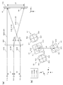
- FIGS. 1A and 1B are diagrams showing an optical system of an optical pickup device 1 according to an embodiment.
- 1A is a plan view of the optical system as viewed from the front side of the optical pickup device 1 (in the positive y-axis direction), and
- FIG. 1B is an internal perspective view of the peripheral portion of the objective lens actuator 122 as viewed from the side.
- FIG. 1C is a diagram showing an arrangement state of the light emitting units in the semiconductor laser 101. In FIGS. 1A to 1C, three-dimensional coordinate axes orthogonal to each other are added.
- the x-axis is parallel to the emission direction of the laser light source 101
- the y-axis is parallel to the optical axis of the objective lens 108
- the z-axis is parallel to the optical axis of the collimator lens 105.
- an optical pickup device 1 includes a semiconductor laser 101, a diffraction grating 102, a PBS mirror 103, a quarter wavelength plate 104, a collimator lens 105, and a lens actuator 106.
- a raising mirror 107, an objective lens 108, a diffraction grating 200, an astigmatism plate 109, and a photodetector 110 are provided.
- the semiconductor laser 101 includes a laser beam with a wavelength of about 400 nm (hereinafter referred to as “BD light”), a laser beam with a wavelength of about 650 nm (hereinafter referred to as “DVD light”), and a laser beam with a wavelength of about 780 nm (hereinafter referred to as “CD light”). Light)) in the same direction.
- BD light laser beam with a wavelength of about 400 nm
- DVD light laser beam with a wavelength of about 650 nm
- CD light laser beam with a wavelength of about 780 nm
- the semiconductor laser 101 includes light emitting units 101a, 101b, and 101c that emit BD light, DVD light, and CD light, respectively, in one package.
- the light emitting units 101b and 101c are integrally formed on the substrate 101e so that the interval is w2.
- the substrates 101d and 101e are installed on the submount 101f.
- the light emitting portions 101a to 101c are formed so as to be aligned on a straight line.
- the optical system after the semiconductor laser 101 is adjusted so that its optical axis is aligned with the optical axis of the DVD light.
- both w1 and w2 are designed to be 90 ⁇ m.
- the light emitting unit 101a and the light emitting units 101b and 101c are formed on the substrates 101d and 101e, respectively, by a semiconductor manufacturing process. For this reason, the positional accuracy of the light emitting unit 101a on the substrate 101d and the positional accuracy of the light emitting units 101b and 101c on the substrate 101e are sufficiently enhanced.
- the substrates 101d and 101e on which the light emitting portions are formed are bonded onto the submount 101f via electrodes, bonding layers, and the like. For this reason, the positional accuracy of the substrates 101d and 101e in the submount 101f is lowered.
- w2 includes only an error of about ⁇ 1 to +1 ⁇ m, but w1 has an error of about ⁇ 10 to +10 ⁇ m.
- the diffraction grating 102 mainly divides BD light out of BD light, DVD light, and CD light emitted from the semiconductor laser 101 into a main beam and two sub beams.
- diffraction grating 102 diffraction grooves are formed so that the three beams of BD light follow the track of the disk.
- DVD light and CD light are also diffracted by the diffraction grating 102, but the intensity of the sub-beams of these lights is extremely small.
- the diffraction grating 102 is a composite element of a half-wave plate and a diffraction grating.
- the PBS mirror 103 reflects the laser beam incident from the diffraction grating 102 side.
- the PBS mirror 103 is a thin parallel plate having a square outline on the entrance surface and the exit surface, and a polarizing film is formed on the entrance surface.
- the diffraction grating 102 is arranged so that the polarization directions of the BD light, DVD light, and CD light are S-polarized with respect to the PBS mirror 103.
- the quarter-wave plate 104 converts the laser light reflected by the PBS mirror 103 into circularly polarized light, and converts the reflected light from the disk into linearly polarized light that is orthogonal to the polarization direction toward the disk. As a result, the laser light reflected by the disk passes through the PBS mirror 103 and is guided to the photodetector 110.
- the collimator lens 105 converts the laser light reflected by the PBS mirror 103 into parallel light.
- the lens actuator 106 drives the quarter wavelength plate 104 and the collimator lens 105 in the optical axis direction of the collimator lens 105. By moving the collimator lens 105, the aberration generated in the laser light is corrected.
- the rising mirror 107 reflects the laser beam incident from the collimator lens 105 side in the direction toward the objective lens 108 (negative y-axis direction).
- the objective lens 108 is held by a holder 121, and the holder 121 is driven by an objective lens actuator 122 in a focus direction (y-axis direction) and a tracking direction (radial direction of the disc). By driving the holder 121 in this way, the objective lens 108 is driven in the focus direction and the tracking direction.
- the optical axis of the laser beam incident on the rising mirror 107 from the collimator lens 105 side is inclined by 67.5 degrees with respect to the tangential direction of the disk. Further, the alignment direction of the main beam and the two sub beams of the BD light traveling from the rising mirror 107 toward the disk coincides with the tangential direction of the disk.
- the reflected light from the disk is converted into linearly polarized light that becomes P-polarized light with respect to the PBS mirror 103 by the quarter-wave plate 104. Thereby, the reflected light from the disk passes through the PBS mirror 103.
- the diffraction grating 200 has a so-called two-step type diffraction groove. That is, the diffraction groove formed in the diffraction grating 200 is a rectangular groove having one bottom surface. The depth of the diffraction groove of the diffraction grating 200 is designed so that the zero-order diffraction efficiency is high for BD light and the first-order diffraction efficiency is high for CD light and DVD light.
- the diffraction grating 200 is arranged so that the diffraction direction is parallel to the x-axis direction. The configuration of the diffraction grating 200 will be described in detail later with reference to FIG.
- DVD light When DVD light enters the diffraction grating 200, it is diffracted in the first-order diffracted light diffracted in the direction approaching the optical axis of the BD light (x-axis negative direction) and in the direction away from the optical axis of the BD light (x-axis positive direction). 1st order diffracted light is generated.
- the first-order diffracted light diffracted in the direction approaching the optical axis of the BD light (x-axis negative direction) and the direction away from the optical axis of the BD light (x-axis positive direction).
- First-order diffracted light is diffracted into
- the first-order diffracted light diffracted in the direction approaching the optical axis of the BD light is referred to as “+ 1st-order diffracted light” and is diffracted in the direction away from the optical axis of the BD light (x-axis positive direction).
- the first-order diffracted light is expressed as “ ⁇ 1st-order diffracted light”.
- the astigmatism plate 109 is a parallel plate and is arranged to be inclined by 45 degrees with respect to the optical axes of BD light, DVD light, and CD light. As a result, astigmatism is introduced to the BD light, DVD light, and CD light incident on the astigmatism plate 109 in a converged state. Since the PBS mirror 103 is a parallel plate and is inclined with respect to the optical axes of the BD light, DVD light, and CD light, the astigmatism is also caused by the PBS mirror 103 in each light. be introduced.
- the astigmatism plate 109 has a thickness, a refractive index, and an inclination direction so that an appropriate astigmatism is introduced into each light by the astigmatism introduced by itself and the astigmatism introduced by the PBS mirror 103. It has been adjusted.
- the light receiving surface of the photodetector 110 is parallel to the xy plane, and a four-divided sensor is disposed on the light receiving surface at a position where BD light, DVD light, and CD light are irradiated.
- the sensor layout of the photodetector 110 will be described later with reference to FIG.
- DOE 300 Prior to describing the configuration of the diffraction grating 200 and the photodetector 110 described above, first, the configuration of the diffractive optical element (DOE) 300 according to the comparative example and the sensor layout of the photodetector 110 when the DOE 300 is used. Will be described with reference to FIGS. 2 (a) and 2 (b). In this comparative example, the DOE 300 is used in place of the diffraction grating 200.
- DOE 300 is used in place of the diffraction grating 200.
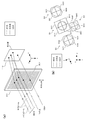
- FIG. 2A is a diagram for explaining the diffraction action by the DOE 300.
- the astigmatism plate 109 disposed between the DOE 300 and the light receiving surface of the photodetector 110 is not shown for convenience.
- the BD light, the DVD light, and the CD light are incident on the DOE 300 in this order in the positive x-axis direction.
- the BD light incident on the DOE 300 is divided into a main beam and a sub beam by a diffraction grating 102 disposed immediately after the semiconductor laser 101.
- the alignment direction of these three beams is a direction corresponding to the tangential direction of the disk, and is slightly inclined with respect to the direction perpendicular to the diffraction direction (the positive x-axis direction) of the DOE 300.
- the three beams of BD light incident on the DOE 300 are bent in the positive x-axis direction by the diffraction action of the DOE 300, and ⁇ 1st order diffracted light is generated.
- the diffracted light other than the ⁇ 1st order of the BD light and the diffracted light other than the 0th order of the DVD light and the CD light are not shown for convenience.
- the ⁇ 1st order diffracted light of the main beam diffracted by the DOE 300 overlaps the 0th order diffracted light of the DVD light on the light receiving surface of the photodetector 110.
- the optical axis of the main beam of BD light and the optical axis of DVD light coincide on the light receiving surface.
- FIG. 2 (b) is a diagram showing four-divided sensors S1 to S4 arranged on the light receiving surface of the photodetector 110.
- FIG. FIG. 2B shows the four-divided sensors S1 to S4 when the photodetector 110 is viewed from the back surface (in the negative z-axis direction).
- the 4-split sensor S1 receives the -1st-order diffracted light of the main beam of BD light and the 0th-order diffracted light of the DVD light, and the 4-split sensors S2 and S3 receive the -1st-order diffracted light of the two sub-beams of BD light.
- the quadrant sensor S4 receives the 0th order diffracted light of the CD light.
- the four-divided sensors S1 to S3 are arranged so as to be inclined so that the arrangement direction of the three four-divided sensors matches the arrangement direction of the three beams of BD light shown in FIG.
- the quadrant sensor S4 is disposed adjacent to the quadrant sensor S1 in the same direction (x-axis direction) as the arrangement direction of the light emitting units 101a to 101c.
- the quadrant sensors S1 to S4 are composed of sensors S11 to S14, sensors S21 to S24, sensors S31 to S34, and sensors S41 to S44, respectively.
- the arrangement direction of the four-divided sensors S1 to S3 is the Y-axis direction
- the direction perpendicular to the Y-axis direction is the X-axis direction
- the X-axis direction and the Y-axis direction are respectively the radial direction of the disc.
- the direction corresponds to the direction and the tangential direction.
- the dividing lines of the four-divided sensors S1 to S4 are configured to coincide with the X-axis direction and the Y-axis direction.
- a reproduction RF signal, a focus error signal, and a tracking error signal are generated by outputs from the respective sensors constituting the four-divided sensors S1 to S4.
- the distance between the optical axis of the 0th-order diffracted light of the DVD light and the optical axis of the 0th-order diffracted light of the CD light is equal to the distance w2 between the light emitting units 101b and 101c shown in FIG. For this reason, the interval between the center of the four-divided sensor S1 and the center of the four-divided sensor S4 is also w2.
- the outlines of the quadrant sensors S1 and S4 are square, and the shapes of the sensors S11 to S14 and S41 to S44 constituting the quadrant sensors S1 and S4 are also square.
- the outlines of the quadrant sensors S2 and S3 have a shape in which square corners are dropped.
- Each of the four-divided sensors S1 and S4 is larger than the diameter of the spot (minimum circle of confusion) of the received laser beam.
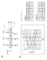
- FIG. 3A is a diagram schematically showing a cross-sectional view when the DOE 300 shown in FIG. 2A is cut along a plane parallel to the xz plane.
- the DOE 300 includes a blazed diffraction structure. That is, a plurality of diffraction grooves 301 extending linearly in the y-axis direction are formed on the incident surface of the DOE 300 at a constant pitch.
- the cross-sectional shape of each diffraction groove 301 is a triangle. Due to the diffraction groove 301, a sawtooth blaze is formed on the incident surface of the DOE 300. Strictly speaking, the slope of each diffraction groove 301 is formed in a stepped shape of 8 steps.
- the DOE 300 is made of a glass material.
- FIG. 3B is a diagram showing the diffraction efficiency of the DOE 300 when the depth of the diffraction groove 301 is changed.
- the pitch of the diffraction grooves 301 is 21.2 ⁇ m and the refractive index of the DOE 300 for each light (the refractive index of the glass) is set as shown in the table on the right side of FIG.
- the simulation results are shown.
- the wavelengths of BD light, DVD light, and CD light are set to 405 nm, 660 nm, and 785 nm, respectively.
- the emission power of BD light is weaker than that of DVD light and CD light.
- the DOE 300 is set so that the ⁇ 1st-order diffraction efficiency of BD light is higher than the 0th-order diffraction efficiency of DVD light and CD light.
- the diffraction efficiency for BD light is about 90%.
- the ⁇ 1st-order diffraction efficiency of the BD light is 88%.
- the zero-order diffraction efficiencies of DVD light and CD light can be set to 33% and 47%, respectively. Thereby, a desired diffraction efficiency can be achieved for each light.
- corresponds to the structure of Claim 2, 4, and 5.
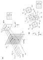
- FIG. 4A is a diagram for explaining the diffraction action by the DOE 300.
- the astigmatism plate 109 disposed between the diffraction grating 200 and the light receiving surface of the photodetector 110 is not shown for convenience.
- the alignment direction of the main beam and the sub beam of the BD light is a direction corresponding to the tangential direction of the disk, and the diffraction direction of the diffraction grating 20000 (x-axis positive direction). It is slightly inclined with respect to the direction perpendicular to
- the three beams of BD light incident on the diffraction grating 200 are not substantially diffracted by the diffraction grating 200 but pass through the diffraction grating 200 as they are.
- DVD light and CD light are bent in the negative x-axis direction by the diffraction action of the diffraction grating 200.
- the diffracted light other than the 0th order of the BD light and the diffracted light other than the + 1st order of the DVD light and the CD light are not shown for convenience.
- the + 1st order diffracted light of the DVD light diffracted by the DOE 300 overlaps with the 0th order diffracted light of the main beam of the BD light on the light receiving surface of the photodetector 110.
- the optical axis of the main beam of BD light and the optical axis of DVD light coincide on the light receiving surface.
- FIG. 4B is a diagram showing the four-divided sensors S1 to S4 arranged on the light receiving surface of the photodetector 110.
- FIG. 4B shows the four-divided sensors S1 to S4 when the photodetector 110 is viewed from the back surface (in the negative z-axis direction).
- the light received by the four-divided sensors S1 to S4 is the same as in the comparative example.
- the quadrant sensors S2 and S3 are configured in the same manner as in the comparative example.
- the four-divided sensors S1 and S4 have a reduced width in the X-axis direction compared to the comparative example.
- the distance between the optical axis of the 0th-order diffracted light of the DVD light and the optical axis of the 0th-order diffracted light of the CD light is the distance between the light emitting units 101b and 101c shown in FIG. Gradually smaller from w2. For this reason, the space
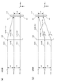
- FIGS. 5A and 5B are diagrams showing diffraction states of BD light, DVD light, and CD light in the comparative example and the example, respectively.
- the DVD light and the CD light travel straight without being diffracted by the DOE 300. Therefore, as described above, the interval w3 between the optical axis of the DVD light and the optical axis of the CD light on the light receiving surface of the photodetector 110 is the same as the interval w2 between the light emitting units 101b and 101c of the semiconductor laser 101. .
- the DVD light and the CD light are each diffracted by the diffraction grating 200, and the + 1st order diffracted light enters the photodetector 110.
- the diffraction angle ⁇ by the diffraction grating 200 is obtained by the following equation.
- the diffraction angle ⁇ c of the + 1st order diffracted light of the CD light is larger than the diffraction angle ⁇ d of the + 1st order diffracted light of the DVD light. For this reason, the distance between the optical axis of the 0th-order diffracted light of the DVD light and the optical axis of the 0th-order diffracted light of the CD light gradually decreases as it advances from the diffraction grating 200 in the positive z-axis direction.
- the interval w3 between the optical axis of the DVD light and the optical axis of the CD light on the light receiving surface of the photodetector 110 is smaller than the interval w2 between the light emitting portions 101b and 101c of the semiconductor laser 101.
- the interval w3 is smaller than the interval w3 in the comparative example, so that the width in the X-axis direction of the four-divided sensors S1, S4 is reduced so that the four-divided sensors S1, S4 do not overlap.
- the outlines of the four-divided sensors S1 and S4 are rectangles that are long in the Y-axis direction.
- the four-divided sensors S1 and S4 are reduced only in the width in the X-axis direction and not reduced in the width in the Y-axis direction. This is for suppressing the influence of the lens shift of the objective lens 108. That is, during actual operation, when the objective lens 108 is displaced in the tracking direction (the radial direction of the disk), the beam spot of each light is displaced in the Y-axis direction in FIG. 4B on the photodetector 110. Thus, even when the beam spot is displaced, the width in the Y-axis direction of the four-divided sensors S1 and S4 is maintained at the same width as in the comparative example so that each beam spot can be properly covered.
- FIG. 6A is a diagram schematically showing a cross-sectional view when the diffraction grating 200 shown in FIG. 4A is cut along a plane parallel to the xz plane.
- the diffraction grating 200 includes a rectangular diffraction groove 201 having one bottom surface. That is, the diffraction grating 200 is a two-step type diffraction grating similar to the diffraction grating 102 shown in FIG.
- a plurality of diffraction grooves 201 extending linearly in the y-axis direction are formed on the incident surface of the diffraction grating 200 at a constant pitch.
- the diffraction groove 201 is formed by forming a protrusion 203 made of SiO 2 on the upper surface of the glass substrate 202.
- the protrusion 203 is formed by forming an SiO 2 layer on the upper surface of the glass substrate 202 and then etching the SiO 2 layer. This configuration is generally used for a two-step type diffraction grating at present.
- FIG. 6B shows the diffraction efficiency of the diffraction grating 200 when the depth of the diffraction groove 201 is changed.
- the pitch of the diffraction grooves 201 is set to 34 ⁇ m
- the refractive index of the projection 203 (the refractive index of SiO 2 ) for each light is set as shown in the table on the right side of FIG. 6B.
- the refractive index of the glass substrate 202 is the same as the refractive index in the table on the right side of FIG.
- the wavelengths of BD light, DVD light, and CD light are set to 405 nm, 660 nm, and 785 nm, respectively.
- the width of the protrusion 203 in the x-axis direction and the width of the diffraction groove 201 in the x-axis direction are set to be equal.
- the emission power of BD light is weaker than that of DVD light and CD light.
- the diffraction grating 200 is set so that the zero-order diffraction efficiency of the BD light is higher than the + 1st-order diffraction efficiency of the DVD light and the CD light.
- the diffraction efficiency for BD light is about 90%.
- the zero-order diffraction efficiency of the BD light is set to 97 as shown in the table on the right side of FIG. %,
- the + 1st order diffraction efficiency of DVD light and CD light can be set to 35% and 40%, respectively.
- the distance in the x-axis direction between the center of the four-divided sensor S1 and the center of the four-divided sensor S4 is a design value (90 ⁇ m in this case) shown in FIG. ) Is set equal to the interval w3.
- Is set equal to the interval w3.
- an error of about ⁇ 10 ⁇ m may occur in the interval w1, and the position of the diffraction grating 200 in the z-axis direction needs to be adjusted according to this error.
- FIG. 7A to 7D are diagrams illustrating a method for adjusting the position of the diffraction grating 200.
- the diffraction grating 200 is positioned at the design position (design position).
- the diffraction grating 200 is moved in the negative z-axis direction from the design position, and the spot of the DVD light and the spot of the CD light are moved in the negative x-axis direction.
- the spot of the DVD light and the spot of the CD light are positioned at the centers of the four-divided sensors S1 and S4, respectively.
- the case where the interval between the light emitting unit 101a and the light emitting unit 101b is larger than the design value w1 has been described.
- the interval between the light emitting unit 101a and the light emitting unit 101b is smaller than the design value w1, diffraction is performed.
- the grating 200 may be moved from the design position in the positive z-axis direction. Thereby, the spot of DVD light and the spot of CD light are positioned at the centers of the four-divided sensors S1 and S4, respectively.
- FIGS. 8A and 8B are diagrams showing the state of the beam spot of each light when the sensor layout according to the comparative example is used, and FIGS. 8C and 8D are the sensors according to the example. It is a figure which shows the state of the beam spot of each light at the time of using a layout.
- the beam spot of these lights is divided into four.
- the size of the four-divided sensors S1 and S4 and the size of the beam spot of each light are adjusted so as to be within the sensors S1 and S4.
- the size of the beam spot is adjusted by changing the magnification of the return path of the optical system shown in FIG. 1A and the magnitude of the astigmatism action by the astigmatism plate 109.
- the main beam of BD light, the DVD light, and the CD light are minimally confused.
- the beam spots of these lights fall within the four-divided sensors S1 and S4.
- the sensor layout of the embodiment since the width in the X-axis direction of the four-divided sensors S1 and S4 is shortened as described above, the main beam of the BD light, the DVD light, and the CD light are converged to the focal line state. In this case, as shown in FIG.
- the beam spot of the main beam of BD light and the beam spot of DVD light and CD light protrude from the four-divided sensors S1 and S4. For this reason, in the sensor layout of the embodiment, there is a concern about deterioration of the focus error signal.
- FIGS. 9A to 9D are diagrams for explaining simulation conditions.
- FIGS. 9A and 9B are diagrams showing the dimensions of the sensor layouts according to the comparative example and the example, respectively. In FIG.
- D1 and D2 are the widths in the Y-axis direction and the X-axis direction of the quadrant sensor S1
- D3 and D4 are the widths in the Y-axis direction and the X-axis direction of the quadrant sensor S4, and D5 is This is the distance between the center of the quadrant sensor S1 and the quadrant sensor S4 in the X-axis direction.
- D11 and D12 are the widths in the Y-axis direction and the X-axis direction of the quadrant sensor S1
- D13 and D14 are the widths in the Y-axis direction and the X-axis direction of the quadrant sensor S4, and D15. Is the distance between the center of the quadrant sensor S1 and the quadrant sensor S4 in the X-axis direction.
- FIG. 9C is a diagram showing a state where the main beam and the sub beam of the BD light are the minimum circle of confusion.
- Db is the diameter of the minimum circle of confusion of BD light.
- FIG. 9D is a diagram illustrating a state when the DVD light and the CD light are each in a minimum circle of confusion.
- Dd and Dc are the diameters of the minimum circle of confusion of DVD light and CD light, respectively.
- D1 to D5 are set as follows.
- D1 90 ⁇ m
- D2 90 ⁇ m
- D3 60 ⁇ m
- D4 60 ⁇ m
- D5 88 ⁇ m
- D11 to D15 are set as follows.
- Db, Dd, and Dc are set as follows.
- Db, Dd, and Dc are set to the same value in both the comparative example and the example.
- the length of the beam when the main beam of the BD light is in the focal line state is equal to the length of the diagonal line of the quadrant sensor S1 in the comparative example, and when the CD light is in the focal line state.
- the length of the beam is equal to the length of the diagonal line of the quadrant sensor S4 in the comparative example.
- 10 (a) to 10 (f) are diagrams showing simulation results of the focus error signal when BD light is used.
- 10A to 10C are diagrams showing simulation results according to the comparative example
- FIGS. 10D to 10F are diagrams showing simulation results according to the example. In this simulation, it is assumed that a focus search is performed on a BD having two recording layers.
- FIG. 10A shows the waveform of the focus error signal (main FE) generated based on the output from the quadrant sensor S1 that receives the main beam of BD light.
- FIG. 10B shows the waveform of the BD light.
- FIG. 10C shows the waveform of the focus error signal (sub FE) generated based on the outputs from the four-divided sensors S2 and S3 that receive the sub beam.
- FIG. 10C shows a focus error signal (main FE and sub FE added) ( The waveform of the FE signal) is shown.
- FIGS. 10D, 10E, and 10F show main FE, sub FE, and FE signals according to the embodiment.
- SL1 and SL2 are Peak-to-Peak values of S-shaped curves for the first recording layer and the second recording layer, respectively.
- the S-shaped level SL1 in the example (the peak-to-peak value of the S-shaped curve for the first recording layer) is 97 of the S-shaped level SL1 in the comparative example. %Met. Therefore, it can be seen that the same focus error signal as in the comparative example can be obtained even if the width in the X-axis direction of the four-divided sensors S1 and S4 is reduced as in the embodiment.
- S-shaped signals also appear in the areas A1 and A2.
- the Fake signal is generated when stray light from the recording layer leaks into the 4-minute sensors S1 to S4. If the amplitude of the Fake signal is large, the Fake signal may be erroneously detected as an S-shaped signal for the second recording layer during focus search. Therefore, the amplitude of the Fake signal needs to be sufficiently smaller than the S-shaped level SL2 for the second recording layer.
- the ratio of the Fake signal to the S-shaped level SL2 was 36%, and in the example, the ratio of the Fake signal to the S-shaped level SL2 was 34%. Therefore, it can be seen that the Fake signal is suppressed as compared with the comparative example by reducing the width in the X-axis direction of the four-divided sensors S1 and S4 as in the embodiment.
- FIGS. 11 (a) and 11 (b) are diagrams showing simulation results of a focus error signal when DVD light is used. In this simulation, it is assumed that a focus search is performed on a DVD having two recording layers.
- FIGS. 11C and 11D are diagrams showing simulation results of the focus error signal when CD light is used. In this simulation, it is assumed that a focus search is performed on a CD having one recording layer.
- 11A and 11C are diagrams illustrating simulation results according to the comparative example
- FIGS. 11B and 11D are diagrams illustrating simulation results according to the example.
- the S-shaped level of the embodiment is slightly lower than the S-shaped level of the comparative example, a focus error signal substantially equivalent to that of the comparative example is obtained. . Therefore, it can be seen that the same focus error signal as in the comparative example can be obtained even if the width in the X-axis direction of the four-divided sensors S1 and S4 is reduced as in the embodiment.
- the diffraction grating 200 Since the diffraction grating 200 has a simple structure in which a rectangular diffraction groove 201 having a single bottom surface is formed, it can be generated at a lower cost than the DOE 300 in the comparative example. Further, by diffracting DVD light and CD light without diffracting BD light, as shown in FIG. 6B, the diffraction efficiency for BD light, DVD light and CD light can be increased to the same level as the comparative example. A solution for the groove depth can be obtained. Furthermore, even if DVD light and CD light are diffracted in this way, as verified with reference to FIGS. 10 and 11, the quality of the focus error signal substantially equivalent to that of the comparative example can be obtained. Therefore, according to the present embodiment, the optical pickup device 1 capable of matching the optical axes of two of the three laser beams with an inexpensive diffraction grating 200 while achieving a desired diffraction efficiency. Can be realized.
- the width of the quadrant sensor S1, S4 in the X-axis direction is reduced, so that the sensor layout can be made compact.
- the quality of the focus error signal substantially equivalent to that of the comparative example can be obtained.
- the width in the X-axis direction of the four-divided sensors S1 and S4 is not reduced, even if a lens shift occurs in the objective lens 108 as described above, the sensor output is deteriorated. It does not occur.
- the objective lens is configured by configuring the four-divided sensors S1, S4 so that the width in the arrangement direction of the four-divided sensors S1, S4 is smaller than the width in the direction perpendicular to the arrangement direction.
- the sensor layout can be made compact while suppressing the influence of the lens shift 108.
- FIGS. 12A and 12B show the configuration of the photodetector 110a according to the first modification.
- the same diffraction grating 200 as that in the first embodiment is used.
- the first modification example exemplifies the configuration described in claim 6.
- the first modification does not limit the configuration of claim 6 in any way.
- the optical axis of the 0th-order diffracted light of the main beam of the BD light and the optical axis of the + 1st-order diffracted light of the CD light coincide on the light receiving surface of the photodetector 101a.
- Two diffracted lights are received by the quadrant sensor S1.
- ⁇ 1st order diffracted light is received by the four-divided sensor S4.
- the photodetector 110a is arranged at a position away from the diffraction grating 200 in the z-axis positive direction as compared with the above embodiment so that each diffracted light can be received by the corresponding four-divided sensor in this way.
- the four-divided sensor S4 receives DVD light having a spot diameter larger than that of CD light, and thus is larger in size than the comparative example. Further, since the interval w3 between the optical axis of the BD light and the optical axis of the DVD light on the light receiving surface is larger than that in the above-described example and the comparative example, the interval between the four-divided sensors S1 and S4 is also the above example and the comparative example. Is bigger than. For this reason, in the first modification, the sensor layout is larger than that in the above-described embodiment and the comparative example.
- the size of the beam spot of CD light and DVD light can be set large.
- the RF signal for the positional deviation in the xy plane of the photodetector 110a Degradation of the tracking error signal and the focus error signal can be suppressed.
- the size of the beam spot can be adjusted by changing the magnification of the return path of the optical system shown in FIG. 1A and the magnitude of the astigmatism action by the astigmatism plate 109.
- Modification 1 is preferable when the photodetector 110a can be increased in size.
- the optical axes of two of the three laser beams can be made to coincide with each other by the inexpensive diffraction grating 200 while achieving the desired diffraction efficiency, as in the above embodiment.
- the optical pickup device 1 can be realized.
- FIGS. 13A and 13B show the configuration of the photodetector 110b according to the second modification.
- the same diffraction grating 200 as that in the first embodiment is used.
- the optical axis of the 0th-order diffracted light of the main beam of the BD light and the optical axis of the + 1st-order diffracted light of the DVD light are the light receiving surface of the photodetector 101b, as in the above embodiment. These two diffracted lights coincide with each other and are received by the four-divided sensor S1.
- the ⁇ 1st order diffracted light of CD light is received by the four-divided sensor S4.
- the photodetector 110a is separated from the diffraction grating 200 in the positive z-axis direction by the same distance as in the above embodiment.
- the size of the four-divided sensors S1 and S4 is the same as that of the comparative example.
- the interval w3 between the optical axis of the BD light and the optical axis of the CD light on the light receiving surface is larger than that of the above-described embodiment and the comparative example, the interval between the four-divided sensors S1, S4 is also the above-described embodiment and comparative example Is bigger than.
- the sensor layout is larger than that in the above-described example and comparative example.
- the size of the four-divided sensors S1 and S4 and the size of the beam spots of BD light, CD light, and DVD light are set large as in the first modification. can do.
- the size of the beam spot can be adjusted by changing the magnification of the return path of the optical system shown in FIG. 1A and the magnitude of the astigmatism action by the astigmatism plate 109.
- the configuration of the second modification is also preferable when the enlargement of the photodetector 110a is allowed, as in the first modification.
- the optical axes of two of the three laser beams can be made to coincide with each other by the inexpensive diffraction grating 200 while achieving the desired diffraction efficiency, as in the above embodiment.
- the optical pickup device 1 can be realized.
- the semiconductor laser 101 is configured such that the BD light emitting unit 101a and the CD light emitting unit 101c sandwich the DVD light emitting unit 101b, but the arrangement order of the light emitting units 101a to 101c is not limited. May be changed to other orders.
- the semiconductor laser 101 may be configured such that the light emitting unit 101a for BD light and the light emitting unit 101b for DVD light sandwich the light emitting unit 101c for CD light.
- this arrangement order is not necessarily a desirable arrangement order. That is, in this arrangement order, when the optical axis of the CD light is made coincident with the optical axis of the objective lens 108, both the BD light and the DVD light are incident on the objective lens 108 with a predetermined angle of view.
- the other laser light is incident on the objective lens 108 with a large angle of view. In this case, there is a possibility that a large aberration occurs in the BD light or DVD light.
- the semiconductor laser 101 is preferably configured such that the light emitting unit 101a for BD light and the light emitting unit 101c for CD light sandwich the light emitting unit 101b for DVD light.
- the so-called three-beam method is applied to the BD light.
- the BD light may be a one-beam method, or the three-beam method is appropriately applied to laser light of other wavelengths. May be.
- the angle between the optical axis of the laser beam incident on the rising mirror 107 from the collimator lens 105 side and the tangential direction of the disk is 67.5 degrees. It is not limited to.
- the present invention can also be appropriately applied to an optical pickup device including an optical system having another configuration.
- Optical pick-up apparatus 101 ... Semiconductor laser (laser light source) 101a ... Light emitting part (first light emitting part) 101b ... Light emitting part (second light emitting part) 101c ... Light emitting part (third light emitting part) 110, 110a, 110b ... Photodetector 200 ... Diffraction grating S1 ... Quadrant sensor (first quadrant sensor) S4: Quadrant sensor (second quadrant sensor)
Landscapes
- Physics & Mathematics (AREA)
- Optics & Photonics (AREA)
- Optical Head (AREA)
- Optical Recording Or Reproduction (AREA)
Description
本発明は、光ピックアップ装置に関するものであり、特に、複数波長のレーザ光を光ディスクに照射する光ピックアップ装置に用いて好適なものである。
従来、複数種類の光ディスクに対応した互換型の光ピックアップ装置が開発されている。かかる光ピックアップ装置では、異なる波長のレーザ光を用いて情報の読み書きが行われる。この種の光ピックアップ装置で用いられる半導体レーザとして、異なる波長の2つのレーザ光を出射する2波長レーザが知られている(たとえば、特許文献1)。さらに、近年では、異なる波長の3つのレーザ光を出射する3波長レーザが用いられつつある。
このように異なる波長のレーザ光を出射する半導体レーザを用いることにより、部品点数の削減を図ることができる。さらに、異なる波長のレーザ光の光軸を光検出器上において一致させることにより、光検出器のセンサレイアウトを簡素化することができる。ここで、2つのレーザ光の光軸を一致させるための光学素子として、たとえば、回折光学素子が用いられる(たとえば、特許文献2)。
上記のように光源として3波長レーザが用いられる場合、回折光学素子は、通常、3つのレーザ光のうち一つのレーザ光の光軸を曲げるように設計される。この場合、各レーザ光の回折効率を高めるために、いわゆるブレーズ型の回折光学素子が用いられる。
しかしながら、ブレーズ型の回折光学素子は、回折溝の構造が複雑であるため高価であり、このため、光ピックアップ装置のコストを引き上げる要因となる。これに対し、3ビーム方式の光ピックアップ装置において、レーザ光をメインビームと2つのサブビームに分割するために用いられる所謂2ステップ型の回折格子は、一つの底面を有する矩形状の溝によって回折溝が形成されているため、回折溝の構造がシンプルあり、ブレーズ型の回折光学素子に比べると、かなり安価である。しかしながら、この回折格子では、一つのレーザ光から同じ次数の2つの回折光(たとえば、+1次回折光と-1次回折光)が生じるため、そのうち一方が光検出器に導かれるように光学系を構成すると、光検出器に導かれる回折光の回折効率が低くなるとの問題がある。
本発明は、上記課題を解消するためになされたものであり、所望の回折効率を達成しながら、安価な回折格子により、3つのレーザ光のうち2つのレーザ光の光軸を一致させることが可能な光ピックアップ装置を提供することを目的とする。
本発明に係る光ピックアップ装置は、第1の波長を持つ第1のレーザ光を出射する第1の発光部と、前記第1の波長よりも長い第2の波長を持つ第2のレーザ光を出射する第2の発光部と、前記第2の波長よりも長い第3の波長を持つ第3のレーザ光を出射する第3の発光部とが直線状に並ぶように一つのパッケージ上に設置されたレーザ光源と、前記第1、第2および第3のレーザ光を受光する光検出器と、前記レーザ光源から出射された前記第1、第2および第3のレーザ光を、それぞれ、第1、第2および第3のディスク上に収束させるとともに、前記第1、第2および第3のディスクからそれぞれ反射された前記第1、第2および第3のレーザ光を、前記光検出器に導く光学系と、を備える。ここで、前記光学系は、前記光検出器へと向かう前記第1、第2および第3のレーザ光が入射する回折格子を備え、この回折格子には、一つの底面を有する矩形状の回折溝が形成されている。前記回折格子の回折方向が前記第1、第2および第3のレーザ光の光軸の並び方向に対して平行となるように、前記回折格子が配置される。前記光検出器は、前記回折格子によって回折されない前記第1のレーザ光と前記回折格子によって回折された前記第2および第3のレーザ光の何れか一方とが重なる位置に配置された第1の4分割センサと、前記回折格子によって回折された前記第3のレーザ光が照射される位置に配置された第2の4分割センサとを備える。
前記回折格子は、前記第1のレーザ光の0次の回折効率が前記第1のレーザ光の他の次数の回折効率よりも高く、前記第2および第3のレーザ光の1次の回折効率が、それぞれ、前記第2および第3のレーザ光の他の次数の回折効率よりも高くなるよう、前記回折溝の深さが設定されている。
本発明によれば、所望の回折効率を達成しながら、安価な回折格子により、3つのレーザ光のうち2つのレーザ光の光軸を一致させることが可能な光ピックアップ装置を提供することができる。
本発明の特徴は、以下に示す実施の形態により更に明らかとなろう。ただし、以下の実施の形態は、あくまでも本発明の一つの実施形態であって、本発明ないし各構成要件の用語の意義は、以下の実施の形態により何ら制限されるものではない。
本実施の形態は、BD[Blu-ray(登録商標) Disc]、DVD(Digital Versatile Disc)およびCD(Compact Disc)にレーザ光を照射する光ピックアップ装置に本発明を適用したものである。
本実施の形態において、発光部101a、101b、101cが、それぞれ、特許請求の範囲に記載の「第1、第2および第3の発光部」に相当し、半導体レーザ101が、特許請求の範囲に記載の「レーザ光源」に相当する。また、回折格子102~非点収差版109および回折格子200が、特許請求の範囲に記載の「光学系」に相当する。また、4分割センサS1および4分割センサS2が、それぞれ、特許請求の範囲に記載の「第1および第2の4分割センサ」に相当する。ただし、実施の形態に記載の構成は、特許請求の範囲の構成を例示するものであって、特許請求の範囲を何ら限定するものではない。
図1(a)、(b)は、実施の形態に係る光ピックアップ装置1の光学系を示す図である。図1(a)は光学系を光ピックアップ装置1の表側から(y軸正方向に)見た場合の平面図、図1(b)は対物レンズアクチュエータ122周辺部分を側面側から見た内部透視図、図1(c)は半導体レーザ101における発光部の配置状態を示す図である。なお、図1(a)~(c)には、それぞれ、互いに直交する3次元座標軸が付記されている。これら座標軸のうち、x軸は、レーザ光源101の出射方向に平行であり、y軸は、対物レンズ108の光軸に平行であり、z軸は、コリメータレンズ105の光軸に平行である。
図1(a)を参照して、光ピックアップ装置1は、半導体レーザ101と、回折格子102と、PBSミラー103と、1/4波長板104と、コリメータレンズ105と、レンズアクチュエータ106と、立ち上げミラー107と、対物レンズ108と、回折格子200と、非点収差板109と、光検出器110とを備える。
半導体レーザ101は、波長400nm程度のレーザ光(以下、「BD光」という)と、波長650nm程度のレーザ光(以下、「DVD光」という)と、波長780nm程度のレーザ光(以下、「CD光」という)を同一方向に出射する。
図1(c)に示すように、半導体レーザ101は、一つのパッケージに、BD光、DVD光、CD光をそれぞれ出射する発光部101a、101b、101cを備える。発光部101b、101cは、基板101e上に間隔がw2となるように一体的に形成されている。発光部101aは、基板101eとは異なる基板101d上に、発光部101a、101bの間隔がw1(w1=w2)となるように形成されている。基板101d、101eは、サブマウント101f上に設置されている。発光部101a~101cは、一直線上に並ぶように形成されている。本実施の形態において、半導体レーザ101以降の光学系は、その光軸がDVD光の光軸に整合するように調整されている。また、本実施の形態では、w1、w2は何れも90μmに設計されている。
ここで、発光部101aと、発光部101b、101cは、それぞれ、半導体製造プロセスによって、基板101d、101e上に形成される。このため、基板101dにおける発光部101aの位置精度と、基板101eにおける発光部101b、101cの位置精度は、十分に高められたものとなる。しかしながら、発光部が形成された基板101d、101eは、電極、接合層等を介して、サブマウント101f上に接合される。このため、サブマウント101fにおける基板101d、101eの位置精度は低くなる。以上の理由により、w2には、-1~+1μm程度の誤差しか含まれないが、w1には、-10~+10μm程度の誤差が生じてしまう。
回折格子102は、半導体レーザ101から出射されたBD光、DVD光、CD光のうち主としてBD光をメインビームと2つのサブビームに分割する。回折格子102には、BD光の3つのビームがディスクのトラックに沿うよう回折溝が形成されている。なお、DVD光とCD光も回折格子102による回折作用を受けるが、これら光のサブビームの強度は、極めて小さくなっている。回折格子102は、1/2波長板と回折格子の複合素子である。
PBSミラー103は、回折格子102側から入射されたレーザ光を反射する。PBSミラー103は、入射面と出射面が正方形の輪郭を有する薄板状の平行平板となっており、その入射面に、偏光膜が形成されている。回折格子102は、BD光、DVD光、CD光の偏光方向がPBSミラー103に対してS偏光となるように配置されている。
1/4波長板104は、PBSミラー103によって反射されたレーザ光を円偏光に変換するとともに、ディスクからの反射光を、ディスクへ向かうときの偏光方向に直交する直線偏光に変換する。これにより、ディスクによって反射されたレーザ光はPBSミラー103を透過して光検出器110へと導かれる。
コリメータレンズ105は、PBSミラー103によって反射されたレーザ光を平行光に変換する。レンズアクチュエータ106は、1/4波長板104とコリメータレンズ105を、コリメータレンズ105の光軸方向に駆動する。コリメータレンズ105が移動されることにより、レーザ光に生じる収差が補正される。
立ち上げミラー107は、コリメータレンズ105側から入射されたレーザ光を対物レンズ108に向かう方向(y軸負方向)に反射する。対物レンズ108は、ホルダ121に保持され、ホルダ121は、対物レンズアクチュエータ122によって、フォーカス方向(y軸方向)およびトラッキング方向(ディスクのラジアル方向)に駆動される。このようにホルダ121が駆動されることにより、対物レンズ108が、フォーカス方向およびトラッキング方向に駆動される。
なお、コリメータレンズ105側から立ち上げミラー107に入射するレーザ光の光軸は、ディスクのタンジェンシャル方向に対して67.5度傾いている。また、立ち上げミラー107からディスクに向かうBD光のメインビームと2つのサブビームの並び方向は、ディスクのタンジェンシャル方向と一致している。
ディスクからの反射光は、1/4波長板104によりPBSミラー103に対してP偏光となる直線偏光に変換される。これにより、ディスクからの反射光は、PBSミラー103を透過する。
回折格子200は、いわゆる2ステップ型の回折溝を有する。すなわち、回折格子200に形成された回折溝は、一つの底面を有する矩形状の溝からなっている。回折格子200の回折溝は、BD光に対しては0次の回折効率が高くなり、CD光とDVD光に対しては1次の回折効率が高くなるよう、深さが設計されている。回折格子200は、回折方向がx軸方向に平行となるように配置される。回折格子200の構成は、追って、図6(a)を参照して詳述する。
DVD光が回折格子200に入射すると、BD光の光軸に近づく方向(x軸負方向)に回折される1次回折光と、BD光の光軸から離れる方向(x軸正方向)に回折される1次回折光が生じる。同様に、CD光が回折格子200に入射すると、BD光の光軸に近づく方向(x軸負方向)に回折される1次回折光と、BD光の光軸から離れる方向(x軸正方向)に回折される1次回折光が生じる。以下では、BD光の光軸に近づく方向(x軸負方向)に回折される1次回折光を「+1次回折光」と表し、BD光の光軸から離れる方向(x軸正方向)に回折される1次回折光を「-1次回折光」と表す。
非点収差板109は、平行平板であり、BD光、DVD光、CD光の光軸に対して45度傾くように配置されている。これにより、非点収差板109に収束状態で入射するBD光、DVD光、CD光に対して、非点収差が導入される。なお、PBSミラー103は、平行平板であり、且つ、BD光、DVD光、CD光の光軸に対して傾いて配置されているため、各光には、PBSミラー103によっても非点収差が導入される。非点収差板109は、自身が導入する非点収差とPBSミラー103によって導入される非点収差とによって、各光に適正な非点収差が導入されるよう、厚み、屈折率、傾き方向が調整されている。
光検出器110の受光面は、xy平面に平行であり、かかる受光面上の、BD光、DVD光、CD光が照射される位置に、4分割センサが配置されている。光検出器110のセンサレイアウトについては、追って、図4(b)を参照して説明する。
<比較例>
上述の回折格子200および光検出器110の構成を説明するに先立って、まず、比較例に係る回折光学素子(DOE)300の構成と、当該DOE300が用いられる場合の光検出器110のセンサレイアウトについて、図2(a)、(b)を参照して説明する。この比較例では、DOE300が、上記回折格子200に置き換えて用いられる。
上述の回折格子200および光検出器110の構成を説明するに先立って、まず、比較例に係る回折光学素子(DOE)300の構成と、当該DOE300が用いられる場合の光検出器110のセンサレイアウトについて、図2(a)、(b)を参照して説明する。この比較例では、DOE300が、上記回折格子200に置き換えて用いられる。
図2(a)は、DOE300による回折作用を説明する図である。なお、図2(a)では、DOE300と光検出器110の受光面との間に配される非点収差板109が、便宜上、図示省略されている。
図2(a)に示すとおり、BD光、DVD光、CD光は、この順に、x軸正方向に並んだ状態でDOE300に入射する。DOE300に入射するBD光は、半導体レーザ101の直後に配された回折格子102によって、メインビームとサブビームに分割されている。これら3つのビームの並び方向は、ディスクのタンジェンシャル方向に対応する方向となっており、DOE300の回折方向(x軸正方向)に垂直な方向に対して僅かに傾いている。
図2(a)に示すように、DOE300に入射するBD光の3つのビームは、DOE300の回折作用によりx軸正方向に曲げられ、-1次の回折光が生成される。なお、図2(a)では、BD光の-1次以外の回折光と、DVD光とCD光の0次以外の回折光は、便宜上、図示されていない。
DOE300により回折されたメインビームの-1次回折光は、光検出器110の受光面上において、DVD光の0次回折光と重なる。こうして、BD光のメインビームの光軸と、DVD光の光軸が、受光面上において一致する。
図2(b)は、光検出器110の受光面上に配される4分割センサS1~S4を示す図である。なお、図2(b)は、光検出器110を裏面から(z軸負方向に)見た場合の4分割センサS1~S4を示している。
4分割センサS1は、BD光のメインビームの-1次回折光とDVD光の0次回折光を受光し、4分割センサS2、S3は、BD光の2つのサブビームの-1次回折光を受光する。また、4分割センサS4は、CD光の0次回折光を受光する。4分割センサS1~S3は、これら3つの4分割センサの並び方向が、図2(a)に示すBD光の3つのビームの並び方向に一致するよう傾いて配置されている。4分割センサS4は、発光部101a~101cの並び方向と同じ方向(x軸方向)に、4分割センサS1と隣り合うように配置される。
4分割センサS1~S4は、それぞれ、センサS11~S14と、センサS21~S24と、センサS31~S34と、センサS41~S44から構成されている。図2(b)において、4分割センサS1~S3の並び方向をY軸方向とし、Y軸方向に垂直な方向をX軸方向とすると、X軸方向とY軸方向は、それぞれ、ディスクのラジアル方向とタンジェンシャル方向に対応する方向となる。4分割センサS1~S4の分割線は、X軸方向とY軸方向に一致するよう構成される。4分割センサS1~S4を構成する各センサからの出力により、再生RF信号、フォーカスエラー信号、トラッキングエラー信号が生成される。
なお、DVD光の0次回折光の光軸とCD光の0次回折光の光軸との間隔は、図1(c)に示す発光部101b、101cの間隔w2に等しい。このため、4分割センサS1の中心と4分割センサS4の中心との間隔もw2である。
比較例において、4分割センサS1、S4の輪郭は、正方形であり、4分割センサS1、S4を構成するセンサS11~S14、S41~S44の形状も、正方形である。4分割センサS2、S3の輪郭は、正方形の角が落とされた形状である。4分割センサS1、S4大きさは、それぞれ、受光するレーザ光のスポット(最小錯乱円)の径よりも広くなっている。
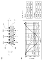
図3(a)は、図2(a)に示すDOE300をx-z平面に平行な面で切断したときの断面図を模式的に示す図である。図3(a)に示すように、DOE300は、ブレーズ型の回折構造を備えている。すなわち、DOE300の入射面には、y軸方向に直線状に延びる複数の回折溝301が一定のピッチで形成されている。図3(a)に示すように、各回折溝301の断面形状は三角形である。かかる回折溝301によって、DOE300の入射面に、鋸歯状のブレーズが形成されている。なお、厳密には、各回折溝301の斜面は、8段ステップの階段形状に形成されている。本比較例において、DOE300は、ガラス材料によって形成されている。
図3(b)は、回折溝301の深さを変えたときのDOE300の回折効率を示す図である。図3(b)の左側には、回折溝301のピッチを21.2μmとし、各光に対するDOE300の屈折率(ガラスの屈折率)を図3(b)の右側の表のように設定したときのシミュレーション結果が示されている。ここでは、BD光、DVD光、CD光の波長は、それぞれ、405nm、660nm、785nmに設定されている。
半導体レーザ101において、BD光の発光パワーは、DVD光およびCD光に比べて弱い。このため、DOE300は、BD光の-1次の回折効率がDVD光およびCD光の0次の回折効率よりも高くなるよう設定される。通常、BD光に対する回折効率は、90%程度であるのが望ましい。
図3(b)の矢印の値に回折溝301の深さdを設定することにより、図3(b)の右側の表に示すように、BD光の-1次の回折効率を88%とすることができ、DVD光とCD光の0次の回折効率を、それぞれ、33%、47%に設定することができる。これにより、各光に対して望ましい回折効率を達成することができる。
<実施例>
次に、実施例に係る回折格子200の構成と、光検出器110のセンサレイアウトについて、図4(a)、(b)を参照して説明する。
次に、実施例に係る回折格子200の構成と、光検出器110のセンサレイアウトについて、図4(a)、(b)を参照して説明する。
なお、本実施例は、請求項2、4、5に記載の構成に対応するものである。
図4(a)は、DOE300による回折作用を説明する図である。なお、図4(a)では、回折格子200と光検出器110の受光面との間に配される非点収差板109が、便宜上、図示省略されている。
図2(a)の場合と同様、BD光のメインビームとサブビームのビームの並び方向は、ディスクのタンジェンシャル方向に対応する方向となっており、回折格子20000の回折方向(x軸正方向)に垂直な方向に対して僅かに傾いている。
本実施例において、回折格子200に入射するBD光の3つのビームは、回折格子200により略回折されず、回折格子200をそのまま透過する。一方、DVD光とCD光は、回折格子200の回折作用によりx軸負方向に曲げられる。図4(a)では、BD光の0次以外の回折光と、DVD光とCD光の+1次以外の回折光は、便宜上、図示されていない。
DOE300により回折されたDVD光の+1次回折光は、光検出器110の受光面上において、BD光のメインビームの0次回折光と重なる。こうして、BD光のメインビームの光軸と、DVD光の光軸が、受光面上において一致する。
図4(b)は、光検出器110の受光面上に配される4分割センサS1~S4を示す図である。なお、図4(b)は、光検出器110を裏面から(z軸負方向に)見た場合の4分割センサS1~S4を示している。
4分割センサS1~S4が受光する光は、上記比較例と同様である。また、4分割センサS2、S3は、上記比較例と同様に構成されている。これに対し、4分割センサS1、S4は、上記比較例に比べ、X軸方向の幅が縮められている。
DVD光の0次回折光の光軸とCD光の0次回折光の光軸との間隔は、回折格子200からz軸正方向に進むにつれて、図1(c)に示す発光部101b、101cの間隔w2から徐々に小さくなる。このため、4分割センサS1の中心と4分割センサS4の中心との間隔は、w2よりも小さくなっている。
図5(a)、(b)は、それぞれ、比較例と実施例におけるBD光、DVD光、CD光の回折状態を示す図である。
図5(a)に示すように、DVD光とCD光は、DOE300により回折されずに直進する。このため、上記のように、光検出器110の受光面上におけるDVD光の光軸とCD光の光軸との間隔w3は、半導体レーザ101の発光部101b、101cの間隔w2と同じである。
これに対し、本実施例では、DVD光とCD光が、それぞれ、回折格子200により回折され、+1次回折光が、光検出器110に入射する。ここで、回折格子200による回折角θは、以下の式によって求められる。
sinθ=mλ/d (m:回折次数)
したがって、CD光の+1次回折光の回折角θcは、DVD光の+1次回折光の回折角θdよりも大きくなる。このため、DVD光の0次回折光の光軸とCD光の0次回折光の光軸との間隔は、回折格子200からz軸正方向に進むにつれて、徐々に小さくなる。その結果、本実施例において、光検出器110の受光面上におけるDVD光の光軸とCD光の光軸との間隔w3は、半導体レーザ101の発光部101b、101cの間隔w2よりも小さくなる。
このように、本実施例では、間隔w3が比較例における間隔w3よりも小さくなるため、4分割センサS1、S4が重なり合わないよう、4分割センサS1、S4のX軸方向の幅が縮められ、図4(b)に示すように、4分割センサS1、S4の輪郭が、Y軸方向に長い長方形となっている。
なお、4分割センサS1、S4は、X軸方向の幅のみが縮められ、Y軸方向の幅は縮められない。これは、対物レンズ108のレンズシフトによる影響を抑制するためのものである。すなわち、実動作時に、対物レンズ108がトラッキング方向(ディスクのラジアル方向)に変位すると、光検出器110上において、各光のビームスポットが、図4(b)のY軸方向に変位する。このようにビームスポットが変位した場合にも、各ビームスポットを適正にカバーできるように、4分割センサS1、S4のY軸方向の幅は、比較例と同様の幅に維持されている。
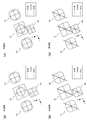
図6(a)は、図4(a)に示す回折格子200をx-z平面に平行な面で切断したときの断面図を模式的に示す図である。図3(a)に示すように、回折格子200は、一つの底面を有する矩形状の回折溝201を備えている。すなわち、回折格子200は、図1(a)に示す回折格子102と同様、2ステップ型の回折格子である。回折格子200の入射面には、y軸方向に直線状に延びる複数の回折溝201が一定のピッチで形成されている。
なお、回折溝201は、ガラス基板202の上面に、SiO2からなる突部203を形成することにより形成される。突部203は、ガラス基板202の上面にSiO2層を形成した後、SiO2層をエッチングすることにより形成される。この構成は、現在、2ステップ型の回折格子に一般的に用いられるものである。
図6(b)は、回折溝201の深さを変えたときの回折格子200の回折効率を示す図である。図6(b)の左側には、回折溝201のピッチを34μmとし、各光に対する突部203の屈折率(SiO2の屈折率)を図6(b)の右側の表のように設定したときのシミュレーション結果が示されている。なお、ガラス基板202の屈折率は、図3(b)の右側の表の屈折率と同様である。ここでは、BD光、DVD光、CD光の波長は、それぞれ、405nm、660nm、785nmに設定されている。また、突部203のx軸方向の幅と回折溝201のx軸方向の幅は等しく設定されている。
上記のように、半導体レーザ101において、BD光の発光パワーは、DVD光およびCD光に比べて弱い。このため、本実施例においても、回折格子200は、BD光の0次の回折効率がDVD光およびCD光の+1次の回折効率よりも高くなるよう設定される。通常、BD光に対する回折効率は、90%程度であるのが望ましい。
図6(b)の矢印の値(862nm)に回折溝201の深さdを設定することにより、図6(b)の右側の表に示すように、BD光の0次の回折効率を97%とすることができ、DVD光とCD光の+1次の回折効率を、それぞれ、35%、40%に設定することができる。これにより、比較例に比べ、CD光の回折効率が15%低下するものの、BD光とDVD光に対する回折効率が、それぞれ、10%および16%高められる。
このように、2ステップ型の単純形状かつ安価な回折格子200によっても、各光に対して望ましい回折効率を実現することができる。
なお、本実施例おいて、4分割センサS1の中心と4分割センサS4の中心との間のx軸方向の距離は、図5(b)に示す間隔w1、w2が設計値(ここでは90μm)であるときの間隔w3と等しく設定されている。しかしながら、上記のように、間隔w1には、±10μm程度の誤差が生じ得るため、この誤差に応じて、回折格子200のz軸方向の位置を調整する必要がある。
図7(a)~(d)は、回折格子200の位置調整方法を例示する図である。なお、回折格子200の位置調整を行う前には、予め、BD光のメインビームと2つのサブビームがそれぞれ4分割センサS1~S3の中心に位置付けられるよう、光検出器110の位置調整が行われる。
たとえば、図7(b)のように、発光部101aと発光部101bの間隔が、設計値w1よりもΔwだけ大きいと、図7(a)に示すように、DVD光のスポットとCD光のスポットが、それぞれ、4分割センサS1、S4の中心からx軸正方向にずれる。なお、図7(b)では、回折格子200が設計時の位置(設計位置)に位置付けられている。この場合、図7(d)に示すように、回折格子200を設計位置からz軸負方向に移動させて、DVD光のスポットとCD光のスポットをx軸負方向に移動させる。これにより、図7(c)に示すように、DVD光のスポットとCD光のスポットが、それぞれ、4分割センサS1、S4の中心に位置付けられる。こうして、回折格子200の位置調整が終了する。
なお、ここでは、発光部101aと発光部101bの間隔が、設計値w1よりも大きい場合について説明したが、発光部101aと発光部101bの間隔が、設計値w1よりも小さい場合には、回折格子200を設計位置からz軸正方向に移動させれば良い。これにより、DVD光のスポットとCD光のスポットが、それぞれ、4分割センサS1、S4の中心に位置付けられる。
図8(a)、(b)は、比較例に係るセンサレイアウトが用いられた場合の各光のビームスポットの状態を示す図、図8(c)、(d)は、実施例に係るセンサレイアウトが用いられた場合の各光のビームスポットの状態を示す図である。
図8(a)、(b)を参照して、比較例では、BD光のメインビームとDVD光およびCD光が焦線状態に収束された場合にも、これらの光のビームスポットが4分割センサS1、S4内に収まるように、4分割センサS1、S4の大きさと、各光のビームスポットの大きさが調整されている。なお、ビームスポットの大きさは、図1(a)に示す光学系の復路の倍率と、非点収差板109による非点収差作用の大きさを変化させることにより調整される。
図8(c)を参照して、各光のビームスポットの大きさが比較例と同様に設定された場合、実施例のセンサレイアウトでは、BD光のメインビームとDVD光およびCD光が最小錯乱円の状態にあるときは、これら光のビームスポットが、4分割センサS1、S4内に収まる。しかしながら、実施例のセンサレイアウトでは、上記のように、4分割センサS1、S4のX軸方向の幅が短縮されているため、BD光のメインビームとDVD光およびCD光が焦線状態に収束された場合には、図8(d)に示すように、BD光のメインビームのビームスポットとDVD光およびCD光のビームスポットが、4分割センサS1、S4からはみ出すこととなる。このため、実施例のセンサレイアウトでは、フォーカスエラー信号の劣化が懸念される。
そこで、本願発明者は、比較例と実施例との場合に生じるフォーカスエラー信号をシミュレーションにより求め、実施例におけるフォーカスエラー信号の劣化具合を評価した。図9(a)~(d)は、シミュレーション条件を説明する図である。図9(a)、(b)は、それぞれ、比較例と実施例に係るセンサレイアウトの寸法を示す図である。図9(a)において、D1、D2は、4分割センサS1のY軸方向およびX軸方向の幅、D3、D4は、4分割センサS4のY軸方向およびX軸方向の幅、D5は、4分割センサS1の中心と4分割センサS4のX軸方向の間隔である。また、図9(b)において、D11、D12は、4分割センサS1のY軸方向およびX軸方向の幅、D13、D14は、4分割センサS4のY軸方向およびX軸方向の幅、D15は、4分割センサS1の中心と4分割センサS4のX軸方向の間隔である。
図9(c)は、BD光のメインビームとサブビームがそれぞれ最小錯乱円であるときの状態を示す図である。図9(c)において、Dbは、BD光の最小錯乱円の径である。図9(d)は、DVD光とCD光がそれぞれ最小錯乱円であるときの状態を示す図である。図9(d)において、Dd、Dcは、それぞれ、DVD光とCD光の最小錯乱円の径である。
本シミュレーションにおいて、D1~D5は、以下のように設定されている。
D1=90μm、
D2=90μm
D3=60μm
D4=60μm
D5=88μm
D2=90μm
D3=60μm
D4=60μm
D5=88μm
また、D11~D15は、以下のように設定されている。
D11=90μm
D12=76μm
D13=60μm
D14=49μm
D15=72μm
D12=76μm
D13=60μm
D14=49μm
D15=72μm
さらに、Db、Dd、Dcは、以下のように設定されている。
Db=63μm
Dd=53μm
Dc=40μm
Dd=53μm
Dc=40μm
なお、Db、Dd、Dcは、比較例と実施例の両方に同じ値が設定されている。また、BD光のメインビームが焦線状態になったときのビームの長さは、比較例における4分割センサS1の対角線の長さに等しく、また、CD光が焦線状態になったときのビームの長さは、比較例における4分割センサS4の対角線の長さに等しい。
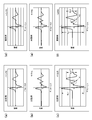
図10(a)~(f)は、BD光を用いた場合のフォーカスエラー信号のシミュレーション結果を示す図である。図10(a)~(c)は、比較例に係るシミュレーション結果を示す図、図10(d)~(f)は、実施例に係るシミュレーション結果を示す図である。かかるシミュレーションは、2つの記録層を持つBDに対してフォーカスサーチが行われたことが想定されている。
図10(a)は、BD光のメインビームを受光する4分割センサS1からの出力に基づいて生成されたフォーカスエラー信号(メインFE)の波形を示し、図10(b)は、BD光のサブビームを受光する4分割センサS2、S3からの出力に基づいて生成されたフォーカスエラー信号(サブFE)の波形を示し、図10(c)は、メインFEとサブFEを加算したフォーカスエラー信号(FE信号)の波形を示している。同様に、図10(d)、(e)、(f)は、実施例に係るメインFE、サブFEおよびFE信号を示している。
図10(c)、(f)を参照して、SL1、SL2は、それぞれ、1層目および2層目の記録層に対するS字カーブのPeak-to-Peak値である。図10(c)、(f)を比較すると、実施例におけるS字レベルSL1(1層目の記録層に対するS字カーブのPeak-to-Peak値)は、比較例におけるS字レベルSL1の97%であった。したがって、実施例のように4分割センサS1、S4のX軸方向の幅を縮めても、比較例と同様のフォーカスエラー信号が得られることが分かる。
なお、図10(c)、(f)では、領域A1、A2にも、S字信号(Fake信号)が現れている。かかるFake信号は、記録層からの迷光が4分センサS1~S4に漏れ込むことにより生じるものである。Fake信号の振幅が大きいと、フォーカスサーチ時に、Fake信号が2層目の記録層に対するS字信号であると誤検出される惧れがある。したがって、Fake信号の振幅は、2層目の記録層に対するS字レベルSL2よりも十分に小さい必要がある。
比較例では、S字レベルSL2に対するFake信号の割合は36%であり、実施例では、S字レベルSL2に対するFake信号の割合は34%であった。したがって、実施例のように4分割センサS1、S4のX軸方向の幅を縮めることにより、比較例に比べてFake信号が抑制されることが分かる。
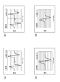
図11(a)、(b)は、DVD光を用いた場合のフォーカスエラー信号のシミュレーション結果を示す図である。かかるシミュレーションは、2つの記録層を持つDVDに対してフォーカスサーチが行われたことが想定されている。図11(c)、(d)は、CD光を用いた場合のフォーカスエラー信号のシミュレーション結果を示す図である。かかるシミュレーションは、1つの記録層を持つCDに対してフォーカスサーチが行われたことが想定されている。図11(a)、(c)は、比較例に係るシミュレーション結果を示す図、図11(b)、(d)は、実施例に係るシミュレーション結果を示す図である。
図11(a)~(d)を参照すると、実施例のS字レベルは、比較例のS字レベルに比べてやや低下するものの、概ね、比較例と同等のフォーカスエラー信号が得られている。したがって、実施例のように4分割センサS1、S4のX軸方向の幅を縮めても、比較例と同様のフォーカスエラー信号が得られることが分かる。
以上の検証より、実施例におけるセンサレイアウトによっても、比較例と略同様のフォーカスエラー信号が得られることが確認できた。
<実施例の効果>
本実施例によれば、以下の効果が奏され得る。
本実施例によれば、以下の効果が奏され得る。
回折格子200は、一つの底面を有する矩形状の回折溝201が形成されたシンプルな構造を有するため、比較例におけるDOE300に比べて、安価に生成することができる。また、BD光を回折させずにDVD光とCD光を回折させることにより、図6(b)に示すように、BD光、DVD光およびCD光に対する回折効率を比較例と同等にまで高め得る溝深さの解を得ることができる。さらに、このようにDVD光とCD光を回折させるようにしても、図10および図11を参照して検証したとおり、比較例と略同等のフォーカスエラー信号の品質が得られる。よって、本実施例によれば、所望の回折効率を達成しながら、安価な回折格子200により、3つのレーザ光のうち2つのレーザ光の光軸を一致させることが可能な光ピックアップ装置1を実現することができる。
さらに、本実施例によれば、図4(b)に示す如く、4分割センサS1、S4のX軸方向の幅が縮められているため、センサレイアウトをコンパクトにすることができる。図10および図11を参照して検証したとおり、このようなコンパクトなセンサレイアウトによっても、比較例と略同等のフォーカスエラー信号の品質を得ることができる。また、図4(b)に示す如く、4分割センサS1、S4のX軸方向の幅が縮められていないため、上記の如く、対物レンズ108にレンズシフトが生じても、センサ出力に劣化が生じることがない。このように、本実施例によれば、4分割センサS1、S4の並び方向の幅が並び方向に垂直な方向の幅よりも小さくなるよう4分割センサS1、S4を構成することにより、対物レンズ108のレンズシフトによる影響を抑制しながら、センサレイアウトをコンパクトにすることができる。
<変更例1>
図12(a)、(b)に変更例1に係る光検出器110aの構成を示す。本変更例1において、回折格子200は、上記実施例1と同様のものが用いられる。
図12(a)、(b)に変更例1に係る光検出器110aの構成を示す。本変更例1において、回折格子200は、上記実施例1と同様のものが用いられる。
なお、本変更例1は、請求項6に記載の構成を例示するものである。しかしながら、この変更例1は、請求項6の構成を何ら限定するものではない。
図12(a)に示すとおり、変更例1では、BD光のメインビームの0次回折光の光軸とCD光の+1次回折光の光軸が光検出器101aの受光面上において一致し、これら2つの回折光が4分割センサS1により受光される。DVD光は、-1次回折光が、4分割センサS4によって受光される。光検出器110aは、このように各回折光を対応する4分割センサで受光できるよう、上記実施例に比べて、回折格子200からz軸正方向に離れた位置に配置される。
図12(b)に示すとおり、4分割センサS4は、CD光よりもスポット径が大きいDVD光を受光するため、上記比較例に比べて、サイズが大きくなっている。また、受光面上におけるBD光の光軸とDVD光の光軸との間隔w3が上記実施例および比較例よりも大きいため、4分割センサS1、S4間の間隔も、上記実施例および比較例よりも大きくなっている。このため、変更例1では、センサレイアウトが、上記実施例および比較例に比べて大きくなる。
その一方、4分割センサS1、S4の間にスペースが生じるため、上記実施例および比較例に比べて、4分割センサS1、S4のサイズと、これら4分割センサS1、S4によって受光されるBD光、CD光およびDVD光のビームスポットのサイズを大きく設定することができる。このように、4分割センサS1、S4のサイズと、BD光、CD光およびDVD光のビームスポットのサイズを大きくすることにより、光検出器110aのx-y平面内の位置ずれに対するRF信号、トラッキングエラー信号およびフォーカスエラー信号の劣化を抑制することができる。上記のように、ビームスポットのサイズは、図1(a)に示す光学系の復路の倍率と、非点収差板109による非点収差作用の大きさを変化させることにより調整され得る。
したがって、本変更例1の構成は、光検出器110aの大型化が許容される場合に用いて好ましいものである。なお、本変更例においても、上記実施例と同様、所望の回折効率を達成しながら、安価な回折格子200により、3つのレーザ光のうち2つのレーザ光の光軸を一致させることが可能な光ピックアップ装置1を実現することができる。
<変更例2>
図13(a)、(b)に変更例2に係る光検出器110bの構成を示す。本変更例2においても、回折格子200は、上記実施例1と同様のものが用いられる。
図13(a)、(b)に変更例2に係る光検出器110bの構成を示す。本変更例2においても、回折格子200は、上記実施例1と同様のものが用いられる。
なお、本変更例2は、請求項7に記載の構成を例示するものである。しかしながら、この変更例2は、請求項7の構成を何ら限定するものではない。
図13(a)に示すとおり、変更例2では、上記実施例と同様、BD光のメインビームの0次回折光の光軸とDVD光の+1次回折光の光軸が光検出器101bの受光面上において一致し、これら2つの回折光が4分割センサS1により受光される。本変更例2では、CD光の-1次回折光が、4分割センサS4によって受光される。光検出器110aは、上記実施例と同様の距離だけ、回折格子200からz軸正方向に離れている。
図13(b)において、4分割センサS1、S4のサイズは、比較例と同じとなっている。また、受光面上におけるBD光の光軸とCD光の光軸との間隔w3が上記実施例および比較例よりも大きいため、4分割センサS1、S4間の間隔も、上記実施例および比較例よりも大きくなっている。このため、変更例2では、上記変更例2と同様、センサレイアウトが、上記実施例および比較例に比べて大きくなる。
その一方、4分割センサS1、S4の間にスペースが生じるため、上記変更例1と同様、4分割センサS1、S4のサイズと、BD光、CD光およびDVD光のビームスポットのサイズを大きく設定することができる。これにより、上記変更例1と同様、光検出器110aのx-y平面内の位置ずれに対するRF信号、トラッキングエラー信号およびフォーカスエラー信号の劣化を抑制することができる。上記のように、ビームスポットのサイズは、図1(a)に示す光学系の復路の倍率と、非点収差板109による非点収差作用の大きさを変化させることにより調整され得る。
したがって、本変更例2の構成も、上記変更例1と同様、光検出器110aの大型化が許容される場合に用いて好ましいものである。なお、本変更例においても、上記実施例と同様、所望の回折効率を達成しながら、安価な回折格子200により、3つのレーザ光のうち2つのレーザ光の光軸を一致させることが可能な光ピックアップ装置1を実現することができる。
以上、本発明の実施の形態および実施例、変更例1、2について説明したが、本発明は、上記実施の形態および実施例、変更例1、2に何ら制限されるものではなく、また、本発明の実施の形態も上記以外に種々の変更が可能である。
たとえば、上記実施の形態では、BD光の発光部101aとCD光の発光部101cがDVD光の発光部101bを挟むように、半導体レーザ101が構成されたが、発光部101a~101cの並び順は、他の順序に変更されても良く、たとえば、BD光の発光部101aとDVD光の発光部101bがCD光の発光部101cを挟むように、半導体レーザ101が構成されても良い。
なお、この並び順の場合、対物レンズ108に対する画角の制限が最も緩やかなCD光の発光部101cが3つの発光部101a~101cの中央に位置付けられるため、現状の対物レンズ108の画角特性を考慮すると、この並び順は、必ずしも望ましい並び順とは言えない。すなわち、この並び順において、CD光の光軸を対物レンズ108の光軸に一致させると、BD光とDVD光の両方が所定の画角を持って対物レンズ108に入射することになり、BD光とDVD光の何れか一方の光軸を対物レンズ108の光軸に一致させると、他方のレーザ光は、大きな画角をもって対物レンズ108に入射することになる。こうなると、BD光またはDVD光に大きな収差が発生する惧れがある。
よって、対物レンズ108に対する画角特性を考慮すると、BD光の発光部101aとCD光の発光部101cがDVD光の発光部101bを挟むように、半導体レーザ101が構成されるのが望ましい。
また、上記実施の形態では、BD光に所謂3ビーム方式が適用されたが、BD光は1ビーム方式であっても良く、あるいは、他の波長のレーザ光に、適宜、3ビーム方式が適用されても良い。
さらに、上記実施の形態では、コリメータレンズ105側から立ち上げミラー107に入射するレーザ光の光軸と、ディスクのタンジェンシャル方向との角度が67.5度であったが、この角度は、これに限定されるものではない。本発明は、他の構成による光学系を備える光ピックアップ装置にも、適宜、適用可能である。
この他、本発明の実施の形態は、特許請求の範囲に示された技術的思想の範囲内において、適宜、種々の変更が可能である。
1 … 光ピックアップ装置
101 … 半導体レーザ(レーザ光源)
101a … 発光部(第1の発光部)
101b … 発光部(第2の発光部)
101c … 発光部(第3の発光部)
110、110a、110b … 光検出器
200 … 回折格子
S1 … 4分割センサ(第1の4分割センサ)
S4 … 4分割センサ(第2の4分割センサ)
101 … 半導体レーザ(レーザ光源)
101a … 発光部(第1の発光部)
101b … 発光部(第2の発光部)
101c … 発光部(第3の発光部)
110、110a、110b … 光検出器
200 … 回折格子
S1 … 4分割センサ(第1の4分割センサ)
S4 … 4分割センサ(第2の4分割センサ)
Claims (8)
- 第1の波長を持つ第1のレーザ光を出射する第1の発光部と、前記第1の波長よりも長い第2の波長を持つ第2のレーザ光を出射する第2の発光部と、前記第2の波長よりも長い第3の波長を持つ第3のレーザ光を出射する第3の発光部とが直線状に並ぶように一つのパッケージ上に設置されたレーザ光源と、
前記第1、第2および第3のレーザ光を受光する光検出器と、
前記レーザ光源から出射された前記第1、第2および第3のレーザ光を、それぞれ、第1、第2および第3のディスク上に収束させるとともに、前記第1、第2および第3のディスクからそれぞれ反射された前記第1、第2および第3のレーザ光を、前記光検出器に導く光学系と、を備え、
前記光学系は、前記光検出器へと向かう前記第1、第2および第3のレーザ光が入射する回折格子を備え、この回折格子には、一つの底面を有する矩形状の回折溝が形成され、
前記回折格子の回折方向が前記第1、第2および第3のレーザ光の光軸の並び方向に対して平行となるように前記回折格子が配置され、
前記光検出器は、前記回折格子によって回折されない前記第1のレーザ光と前記回折格子によって回折された前記第2および第3のレーザ光の何れか一方とが重なる位置に配置された第1の4分割センサと、前記回折格子によって回折された前記第3のレーザ光が照射される位置に配置された第2の4分割センサとを備える、
ことを特徴とする光ピックアップ装置。 - 請求項1に記載の光ピックアップ装置において、
前記回折格子は、前記第1のレーザ光の0次の回折効率が前記第1のレーザ光の他の次数の回折効率よりも高く、前記第2および第3のレーザ光の1次の回折効率が、それぞれ、前記第2および第3のレーザ光の他の次数の回折効率よりも高くなるよう、前記回折溝の深さが設定されている、
ことを特徴とする光ピックアップ装置。 - 請求項2に記載の光ピックアップ装置において、
前記第1、第2および第3の発光部は、前記第1および第3の発光部が前記第2の発光部を挟むように前記パッケージに設置されている、
ことを特徴とする光ピックアップ装置。 - 請求項3に記載の光ピックアップ装置において、
前記回折格子によって前記第2のレーザ光から生じる2つの1次回折光のうち、前記第1のレーザ光の0次回折光に近づく方を+1次回折光と表し、前記0次回折光から離れる方を-1次回折光と表し、さらに、前記回折格子によって前記第3のレーザ光から生じる2つの1次回折光のうち、前記0次回折光に近づく方を+1次回折光と表し、前記0次回折光から離れる方を-1次回折光と表す場合、
前記第1の4分割センサは、前記第1のレーザ光の前記0次回折光と前記第2のレーザ光の前記+1次回折光とが重なる位置に配置され、前記第2の4分割センサは、前記第3のレーザ光の前記+1次回折光が照射される位置に配置される、
ことを特徴とする光ピックアップ装置。 - 請求項4に記載の光ピックアップ装置において、
前記第1および第2の4分割センサは、それぞれ、2つの分割線のうち一方が前記回折格子による回折方向に平行となっており、
前記第2の4分割センサは、前記第1および第2の4分割センサの並び方向の幅が前記並び方向に垂直な方向の幅よりも小さくなっている、
ことを特徴とする光ピックアップ装置。 - 請求項3に記載の光ピックアップ装置において、
前記回折格子によって前記第2のレーザ光から生じる2つの1次回折光のうち、前記第1のレーザ光の0次回折光に近づく方を+1次回折光と表し、前記0次回折光から離れる方を-1次回折光と表し、さらに、前記回折格子によって前記第3のレーザ光から生じる2つの1次回折光のうち、前記0次回折光に近づく方を+1次回折光と表し、前記0次回折光から離れる方を-1次回折光と表す場合、
前記第1の4分割センサは、前記第1のレーザ光の前記0次回折光と前記第3のレーザ光の前記+1次回折光とが重なる位置に配置され、前記第2の4分割センサは、前記第2のレーザ光の前記-1次回折光が照射される位置に配置される、
ことを特徴とする光ピックアップ装置。 - 請求項3に記載の光ピックアップ装置において、
前記回折格子によって前記第2のレーザ光から生じる2つの1次回折光のうち、前記第1のレーザ光の0次回折光に近づく方を+1次回折光と表し、前記0次回折光から離れる方を-1次回折光と表し、さらに、前記回折格子によって前記第3のレーザ光から生じる2つの1次回折光のうち、前記0次回折光に近づく方を+1次回折光と表し、前記0次回折光から離れる方を-1次回折光と表す場合、
前記第1の4分割センサは、前記第1のレーザ光の前記0次回折光と前記第2のレーザ光の前記+1次回折光とが重なる位置に配置され、前記第2の4分割センサは、前記第3のレーザ光の前記-1次回折光が照射される位置に配置される、
ことを特徴とする光ピックアップ装置。 - 請求項1ないし7の何れか一項に記載の光ピックアップ装置において、
前記第1、第2および第3のディスクは、それぞれ、BD、DVDおよびCDである、
ことを特徴とする光ピックアップ装置。
Applications Claiming Priority (2)
| Application Number | Priority Date | Filing Date | Title |
|---|---|---|---|
| JP2012158267A JP2015172985A (ja) | 2012-07-17 | 2012-07-17 | 光ピックアップ装置 |
| JP2012-158267 | 2012-07-17 |
Publications (1)
| Publication Number | Publication Date |
|---|---|
| WO2014013719A1 true WO2014013719A1 (ja) | 2014-01-23 |
Family
ID=49948561
Family Applications (1)
| Application Number | Title | Priority Date | Filing Date |
|---|---|---|---|
| PCT/JP2013/004337 Ceased WO2014013719A1 (ja) | 2012-07-17 | 2013-07-16 | 光ピックアップ装置 |
Country Status (2)
| Country | Link |
|---|---|
| JP (1) | JP2015172985A (ja) |
| WO (1) | WO2014013719A1 (ja) |
Families Citing this family (1)
| Publication number | Priority date | Publication date | Assignee | Title |
|---|---|---|---|---|
| JP6399152B2 (ja) * | 2017-05-31 | 2018-10-03 | 日立化成株式会社 | 液状感光性接着剤、接着剤層付き半導体ウェハの製造方法、半導体装置の製造方法及び半導体素子付き半導体ウェハの製造方法 |
Citations (4)
| Publication number | Priority date | Publication date | Assignee | Title |
|---|---|---|---|---|
| JPH11134702A (ja) * | 1997-10-30 | 1999-05-21 | Sanyo Electric Co Ltd | 光ピックアップ装置 |
| JP2001250253A (ja) * | 2000-03-02 | 2001-09-14 | Sony Corp | 光学装置、光ディスク装置、及びこれらの光スポット調整方法 |
| JP2005259268A (ja) * | 2004-03-11 | 2005-09-22 | Sanyo Electric Co Ltd | 光ピックアップ装置および半導体レーザ |
| JP2006099941A (ja) * | 2004-08-30 | 2006-04-13 | Sanyo Electric Co Ltd | 光ピックアップ装置 |
-
2012
- 2012-07-17 JP JP2012158267A patent/JP2015172985A/ja active Pending
-
2013
- 2013-07-16 WO PCT/JP2013/004337 patent/WO2014013719A1/ja not_active Ceased
Patent Citations (4)
| Publication number | Priority date | Publication date | Assignee | Title |
|---|---|---|---|---|
| JPH11134702A (ja) * | 1997-10-30 | 1999-05-21 | Sanyo Electric Co Ltd | 光ピックアップ装置 |
| JP2001250253A (ja) * | 2000-03-02 | 2001-09-14 | Sony Corp | 光学装置、光ディスク装置、及びこれらの光スポット調整方法 |
| JP2005259268A (ja) * | 2004-03-11 | 2005-09-22 | Sanyo Electric Co Ltd | 光ピックアップ装置および半導体レーザ |
| JP2006099941A (ja) * | 2004-08-30 | 2006-04-13 | Sanyo Electric Co Ltd | 光ピックアップ装置 |
Also Published As
| Publication number | Publication date |
|---|---|
| JP2015172985A (ja) | 2015-10-01 |
Similar Documents
| Publication | Publication Date | Title |
|---|---|---|
| CN101252006B (zh) | 光头及光学信息记录再现装置 | |
| CN102831905B (zh) | 光拾取器装置及光盘装置 | |
| JP2000076689A (ja) | 光ピックアップ装置 | |
| JP2010040072A (ja) | 光ピックアップ装置および焦点調整方法 | |
| CN101086872B (zh) | 光拾取器和光盘装置 | |
| JP2015172985A (ja) | 光ピックアップ装置 | |
| JP4301980B2 (ja) | 光ピックアップ装置および半導体レーザ | |
| JP5433533B2 (ja) | 光ピックアップ装置および光ディスク装置 | |
| JP4222988B2 (ja) | 光ピックアップ装置および光ディスク装置 | |
| JP2001028145A (ja) | 光学ヘッド装置及びディスク録再装置 | |
| JP2005203041A (ja) | 光集積ユニットおよび光ピックアップ装置 | |
| JP4312214B2 (ja) | 光ピックアップ装置 | |
| JP2014175030A (ja) | 光集積素子、光ヘッド装置、及び光ディスク装置 | |
| JP4437806B2 (ja) | 光集積ユニットおよびそれを備えた光ピックアップ装置 | |
| JP2013222484A (ja) | 光検出器の位置調整方法および光ピックアップ装置 | |
| KR101275322B1 (ko) | 광픽업 및 이를 적용한 광정보저장매체 시스템 | |
| JP2012014767A (ja) | 光ピックアップ装置 | |
| CN102651223A (zh) | 光学头 | |
| JP2008052823A (ja) | 球面収差補正装置 | |
| JP2014106983A (ja) | 光ピックアップ装置における光検出器の位置調整方法および光ピックアップ装置 | |
| JP2015109117A (ja) | 光ピックアップ装置 | |
| CN1953072A (zh) | 光拾取装置 | |
| JP2012018740A (ja) | 光ピックアップ | |
| JP2011198421A (ja) | 光ピックアップ、および光情報処理装置 | |
| WO2013114748A1 (ja) | 光ピックアップ装置および光ピックアップ装置の調整方法 |
Legal Events
| Date | Code | Title | Description |
|---|---|---|---|
| 121 | Ep: the epo has been informed by wipo that ep was designated in this application |
Ref document number: 13820235 Country of ref document: EP Kind code of ref document: A1 |
|
| NENP | Non-entry into the national phase |
Ref country code: DE |
|
| 122 | Ep: pct application non-entry in european phase |
Ref document number: 13820235 Country of ref document: EP Kind code of ref document: A1 |
|
| NENP | Non-entry into the national phase |
Ref country code: JP |