WO2014010727A1 - 移動体の進行方向推定装置及び進行方向推定方法 - Google Patents
移動体の進行方向推定装置及び進行方向推定方法 Download PDFInfo
- Publication number
- WO2014010727A1 WO2014010727A1 PCT/JP2013/069152 JP2013069152W WO2014010727A1 WO 2014010727 A1 WO2014010727 A1 WO 2014010727A1 JP 2013069152 W JP2013069152 W JP 2013069152W WO 2014010727 A1 WO2014010727 A1 WO 2014010727A1
- Authority
- WO
- WIPO (PCT)
- Prior art keywords
- vector
- component
- acceleration
- traveling direction
- direction vector
- Prior art date
- Legal status (The legal status is an assumption and is not a legal conclusion. Google has not performed a legal analysis and makes no representation as to the accuracy of the status listed.)
- Ceased
Links
Images






Classifications
-
- G—PHYSICS
- G01—MEASURING; TESTING
- G01C—MEASURING DISTANCES, LEVELS OR BEARINGS; SURVEYING; NAVIGATION; GYROSCOPIC INSTRUMENTS; PHOTOGRAMMETRY OR VIDEOGRAMMETRY
- G01C21/00—Navigation; Navigational instruments not provided for in groups G01C1/00 - G01C19/00
- G01C21/10—Navigation; Navigational instruments not provided for in groups G01C1/00 - G01C19/00 by using measurements of speed or acceleration
-
- G—PHYSICS
- G01—MEASURING; TESTING
- G01P—MEASURING LINEAR OR ANGULAR SPEED, ACCELERATION, DECELERATION, OR SHOCK; INDICATING PRESENCE, ABSENCE, OR DIRECTION, OF MOVEMENT
- G01P13/00—Indicating or recording presence, absence, or direction, of movement
- G01P13/02—Indicating direction only, e.g. by weather vane
-
- G—PHYSICS
- G01—MEASURING; TESTING
- G01C—MEASURING DISTANCES, LEVELS OR BEARINGS; SURVEYING; NAVIGATION; GYROSCOPIC INSTRUMENTS; PHOTOGRAMMETRY OR VIDEOGRAMMETRY
- G01C21/00—Navigation; Navigational instruments not provided for in groups G01C1/00 - G01C19/00
- G01C21/10—Navigation; Navigational instruments not provided for in groups G01C1/00 - G01C19/00 by using measurements of speed or acceleration
- G01C21/12—Navigation; Navigational instruments not provided for in groups G01C1/00 - G01C19/00 by using measurements of speed or acceleration executed aboard the object being navigated; Dead reckoning
- G01C21/16—Navigation; Navigational instruments not provided for in groups G01C1/00 - G01C19/00 by using measurements of speed or acceleration executed aboard the object being navigated; Dead reckoning by integrating acceleration or speed, i.e. inertial navigation
-
- G—PHYSICS
- G01—MEASURING; TESTING
- G01C—MEASURING DISTANCES, LEVELS OR BEARINGS; SURVEYING; NAVIGATION; GYROSCOPIC INSTRUMENTS; PHOTOGRAMMETRY OR VIDEOGRAMMETRY
- G01C22/00—Measuring distance traversed on the ground by vehicles, persons, animals or other moving solid bodies, e.g. using odometers, using pedometers
- G01C22/006—Pedometers
-
- G—PHYSICS
- G01—MEASURING; TESTING
- G01P—MEASURING LINEAR OR ANGULAR SPEED, ACCELERATION, DECELERATION, OR SHOCK; INDICATING PRESENCE, ABSENCE, OR DIRECTION, OF MOVEMENT
- G01P15/00—Measuring acceleration; Measuring deceleration; Measuring shock, i.e. sudden change of acceleration
-
- G—PHYSICS
- G01—MEASURING; TESTING
- G01P—MEASURING LINEAR OR ANGULAR SPEED, ACCELERATION, DECELERATION, OR SHOCK; INDICATING PRESENCE, ABSENCE, OR DIRECTION, OF MOVEMENT
- G01P3/00—Measuring linear or angular speed; Measuring differences of linear or angular speeds
Definitions
- the present invention relates to a technique for estimating the traveling direction of a moving object.
- Non-Patent Document 1 based on the measurement data of a self-contained sensing device (acceleration sensor, magnetic sensor, gyroscope, barometric pressure sensor, etc.) built in a terminal held by a mobile object (for example, a pedestrian), the mobile object relative to the world coordinate system is used. The movement direction is estimated (Non-Patent Document 1).
- a self-contained sensing device acceleration sensor, magnetic sensor, gyroscope, barometric pressure sensor, etc.
- Non-Patent Document 1 specifically discloses a technique for tracking a gravity direction vector and a horizontal reference direction vector.
- a method based on the so-called AHRS (Attitude and Heading Reference System) is also known.
- the terminal In the traveling direction vector of (3), when the self-contained sensing device is fixed to the toe or waist of a pedestrian that is a moving body, the terminal is equipped with a self-contained sensing device, and the pedestrian holds the terminal
- the technical issues to be considered differ greatly from the case in which fluctuates freely.
- the self-contained sensing device when the self-contained sensing device is fixed, since the positional relationship between the self-contained sensing device and the pedestrian is fixed at the mounting position, tracking of the moving direction of the moving body is generally known and relatively easy. is there. However, when the holding position or holding posture of the self-contained sensing device is free, it is not easy to track the traveling direction.
- Patent Document 1 various methods have been proposed for estimating the traveling direction (Patent Document 1 and Patent Document 2), but the traveling direction cannot be estimated with high accuracy by these methods.
- the acceleration vector (3 axes) and angular velocity vector (3 axes) are set in the traveling direction and the vertical direction (gravity direction) and in the left-right direction ( It is disclosed in Non-Patent Document 2 that each component has frequency characteristics as shown in Table 1 below when the components are correctly decomposed in the horizontal direction. That is, when the acceleration vector and the angular velocity vector can be decomposed so as to satisfy the properties shown in Table 1, the directions can be considered to be the optimal traveling direction and the left-right direction (lateral direction).
- Non-Patent Document 2 only suggests that the azimuth angle is continuously changed by a necessary resolution as an algorithm for estimating the traveling azimuth, and no specific implementation method has been disclosed.
- Patent Document 4 discloses a cross-correlation between acceleration and angular velocity and a position in the frequency domain in order to identify a human motion. A technique focusing on the phase difference is disclosed.
- JP 2009-156660 A Japanese Unexamined Patent Publication No. 2011-237452 JP 2011-245285 A JP 2012-145457 A
- the self-contained sensing device When the self-contained sensing device is held by a moving body, for example, when the person walks while swinging his arm while being held by a person's hand, the holding position of the self-contained sensing device and the posture of the moving body are When the positional relationship between the self-contained sensing device and the moving body is variable due to the change, there is a problem that it is difficult to correctly estimate the traveling direction of the moving body using the device.
- the present invention has been made to solve such a problem, and an object of the present invention is to provide an apparatus and method capable of accurately estimating the traveling direction of a moving body.
- a traveling direction estimation apparatus includes an acceleration measuring unit that measures acceleration vector component data of a moving body, an angular velocity measuring unit that measures angular velocity vector component data of the moving body, and an acceleration vector. Based on the component data and the angular velocity vector component data, the gravitational direction vector estimation unit that estimates the gravitational direction vector of the moving object, and the provisional traveling direction vector and the left-right direction vector based on the gravity direction vector output by the gravity direction vector estimation unit.
- the tentative travel direction vector generation unit to generate and the component data obtained by projecting the acceleration vector component data after removing the gravity direction vector from the acceleration component data to the gravity direction vector, and outputting the frequency domain component to calculate the walking frequency
- a walking frequency calculation unit for obtaining the phase of the frequency component and a provisional traveling direction vector Based on the gravity direction vector and the acceleration vector component data, the component data obtained by projecting the acceleration vector component data after removing the gravity acceleration vector from the acceleration vector component data to the provisional traveling direction vector is calculated, and the frequency domain component is calculated.
- the calculation unit that calculates the data and outputs the frequency domain component, the provisional traveling direction vector, and the angular velocity vector component data Based on the calculation unit that calculates the data and outputs the frequency domain component, the provisional traveling direction vector, and the angular velocity vector component data, the component obtained by projecting the angular velocity vector component data onto the provisional traveling direction vector is calculated, and the frequency is calculated.
- Calculation unit that outputs region component, horizontal vector, angular velocity Based on the vector component data, a component that projects the angular velocity vector component data onto the left-right direction vector, calculates the frequency domain component, and outputs the frequency domain component, the walking frequency, and the frequency domain component projected from the acceleration component traveling direction vector
- the frequency component of the walking frequency or the walking frequency based on the projected frequency domain component of the acceleration component lateral vector, the projected frequency domain component of the angular velocity traveling direction vector, and the projected frequency domain component of the angular velocity lateral vector
- the objective function is obtained, the phase of the frequency component of the walking frequency is calculated from the frequency domain component projected by the acceleration component traveling direction vector, and the walking frequency calculating unit If the phase difference is within the specified range, the value of the objective function is calculated.
- the traveling direction estimation method includes a first step of measuring acceleration vector component data and angular velocity vector component data of a moving body, and an acceleration measured in the first step. Based on the vector component data and the angular velocity vector component data, a second step of estimating the gravitational direction vector of the moving body, and a provisional traveling direction vector and a lateral direction vector based on the gravitational direction vector estimated in the second step Component data obtained by projecting the acceleration vector component data after removing the gravitational direction vector estimated in the second step from the acceleration vector component data measured in the first step and the third step to be generated. And calculate the walking frequency and the phase of the frequency component by outputting the frequency domain component.
- the third step Based on the temporary travel direction vector generated in the fourth step, the third step, the gravity direction vector estimated in the second step, and the acceleration vector component data measured in the first step
- the component data obtained by projecting the acceleration vector component data after removing the gravitational acceleration vector from the vector component data to the provisional travel direction vector is calculated, and the frequency domain component is estimated in the fifth step and the second step.
- the acceleration vector component after removing the gravity acceleration vector from the acceleration vector component data Calculate the component data obtained by projecting the data into the left-right vector, and obtain the frequency domain component.
- the angular velocity vector component data is converted into the horizontal direction based on the seventh step for obtaining the frequency domain component, the horizontal vector generated in the third step, and the angular velocity vector component data measured in the first step.
- the power value is calculated from the frequency component of the walking frequency or the frequency component of half the walking frequency to obtain the objective function
- the traveling direction vector of the acceleration vector component data Calculate the phase of the frequency component of the walking frequency from the frequency domain component projected above, and obtain the phase difference from the phase of the walking frequency calculated by the walking frequency calculation unit.
- the positional relationship between the self-contained sensing device and the moving body is variable by changing the holding position or posture of the self-contained sensing device. Also, the traveling direction can be estimated with high accuracy.
- FIG. 1 It is a block diagram which shows the fundamental structure of the advancing direction estimation apparatus of the moving body which concerns on 1st embodiment of this invention. It is a figure which shows the power spectrum of the acceleration component Ag of a gravitational direction. It is a figure which shows the power spectrum of the acceleration component Af of a temporary advance direction. It is a figure which shows the power spectrum of the angular velocity component Ws centering on a provisional advancing direction. It is a figure which shows the power spectrum of the angular velocity component Wn around the axis
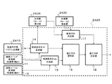
- FIG. 1 is a functional block diagram illustrating a basic configuration of a moving body traveling direction estimation apparatus according to the first embodiment of the present invention.
- the traveling direction estimation apparatus shown in FIG. 1 includes acceleration sensors (three axes) 2401, 2402, attached to a terminal device such as a smartphone or a mobile terminal that is mounted or held on a moving body (for example, a pedestrian) as a measurement unit. 2403 and angular velocity sensors (three axes) 2404, 2405, 2406. These sensors do not necessarily require output in the same coordinate system, but are finally converted so that they can be handled by the same Cartesian coordinate system (X / Y / Z axes) after coordinate conversion. Shall.
- the acceleration component (x) 2401, acceleration component (y) 2402, and acceleration component (z) 2403 that make up the acceleration sensor are the X-axis of the sensor coordinate system whose relative attitude angle is known with respect to the moving body, Measures and outputs Y-axis and Z-axis acceleration vector component data.
- angular velocity sensors 2404, 2405, and 2406 measure and output angular velocity component data of the X axis, Y axis, and Z axis, respectively.
- the acceleration vector component data and the angular velocity vector component data do not necessarily have to be the component data itself output from the sensor.
- the acceleration vector and the angular velocity vector offset or sensitivity corrected data may be output. Good.
- a temperature compensation calibration process may be realized by a separately incorporated temperature sensor.
- the gravity direction vector estimation unit 2407 is a processing unit that receives the acceleration component (three axes) and the angular velocity component (three axes) as inputs and estimates and outputs the gravity direction vector of the moving object. Such processing can be realized by a conventional method.
- a direction vector (unit vector) orthogonal to both the direction vector and the vertical direction (gravity direction) can be determined, and this is set as a provisional lateral direction vector.
- the provisional traveling direction vector generation unit 2413 When one traveling direction vector is generated, the provisional traveling direction vector generation unit 2413 generates a lateral product vector at the same time by calculating an outer product vector with the gravity direction vector. That is, when 720 provisional travel direction vectors are generated, 720 corresponding left-right direction vectors are also generated.
- acceleration component (Acceleration component) Advancing direction vector Af projection calculation unit 2415 receives the acceleration vector (three axes), the output of gravitational direction vector estimation unit 2407, and the output of provisional advancing direction vector generation unit 2413 as its inputs, from the acceleration vector to the gravitational acceleration vector.
- the magnitude of the component obtained by projecting the motion acceleration vector after removing the motion vector onto the traveling direction vector output from the provisional traveling direction vector generation unit 2413 is calculated and output.
- the left-right direction vector An projection calculation unit 2416 receives the acceleration vector (three axes), the output of the gravity direction vector estimation unit 2407, and the output of the provisional travel direction vector generation unit 2413 as inputs, and the acceleration vector from the acceleration vector. The magnitude of the component obtained by projecting the motion acceleration vector after removing the motion vector onto the left-right direction vector output by the provisional travel direction vector generation unit 2413 is calculated and output.
- the traveling direction vector Ws projection calculation unit 2417 receives the angular velocity vector (three axes) and the output of the provisional traveling direction vector generation unit 2413 as inputs, and calculates the magnitude of the component obtained by projecting the angular velocity vector onto the traveling direction vector. Calculate and output.
- the left-right direction vector Wn projection calculation unit 2418 receives the angular velocity vector (three axes) and the output of the provisional traveling direction vector generation unit 2413 as its inputs, and calculates the magnitude of the component obtained by projecting the angular velocity vector onto the left-right direction vector. Calculate and output.
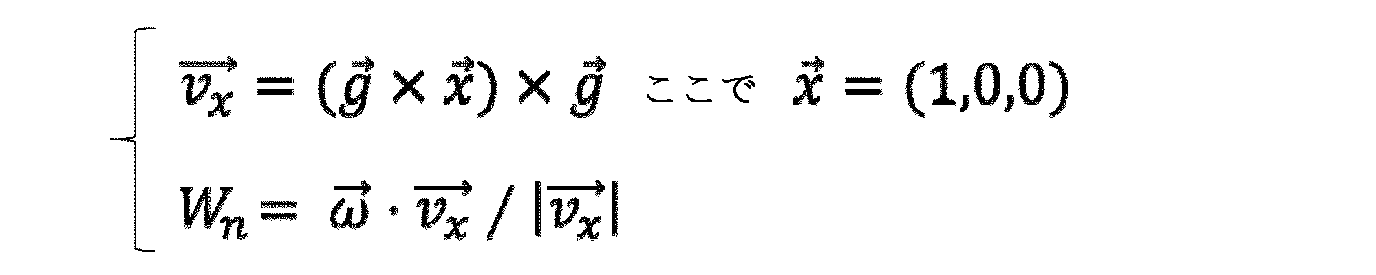
- the (angular velocity component) left-right direction vector Wn projection calculation unit 2418 calculates the angular velocity component Wn in the left-right direction by any one of the following three formulas [Equation 1] to [Equation 3]. .
- the g vector represents a gravity direction vector and has components (g x , g y , g z ).
- the ⁇ vector represents an angular velocity vector and has components ( ⁇ x , ⁇ y , ⁇ z ).
- the lateral direction is the most of the X, Y, and Z axes during the traveling operation period in the sensor coordinate system of the traveling direction estimation device. It is determined by calculating using the approaching axis. That is, for example, when it is known in advance that the Z-axis is closest, the angular velocity component Wn in the left-right direction is calculated using the formula shown in [Equation 3].
- the alternative axis is determined in advance, and Recalculate with components using axes.
- the angular velocity component Wn in the direction is calculated and falls below the threshold, the angular velocity component Wn in the left-right direction is calculated by the equation shown in [Equation 1].
- a smartphone or the like is used as the sensing means of the traveling direction estimation device, but in this case, in the normal way of holding the smartphone by a person, the main surface (screen) of the smartphone has In many cases, a vertical axis (this is referred to as a Z-axis) coincides with a rotation axis for swinging the arm. Therefore, the previously determined axis is the Z axis.
- the short side axis is an alternative because it is the most likely pattern to hold and hold the short side of the screen with one hand. It becomes an axis, and it is understood that this should be decided as the X axis.
- the buffer 2430 is a one-dimensional buffer that stores the output of the (acceleration component) gravity direction vector projection calculation unit 2414.
- the buffering is generally realized by a FIFO, but a buffer that maintains the stored time order is sufficient. The same applies to the following buffers 2430 to 2434.
- the buffer 2431 is a one-dimensional buffer that stores the output of the (acceleration component) traveling direction vector projection calculation unit 2415.
- the buffer 2432 is a one-dimensional buffer that stores the output of the (acceleration component) left-right direction vector projection calculation unit 2416.
- the buffer 2433 is a one-dimensional buffer that stores the output of the (angular velocity component) traveling direction vector projection calculation unit 2417.
- the buffer 2434 is a one-dimensional buffer that stores the output of the (angular velocity component) left-right direction vector projection calculation unit 2418.
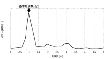
- the one-dimensional FFT operation unit 2419 performs a one-dimensional discrete Fourier transform operation on a predetermined sample data length (for example, 512 samples) based on the acceleration component data stored in the buffer 2430, and is subjected to frequency domain conversion. It is a device that outputs the data. That is, the one-dimensional FFT calculation unit 2419 calculates the peak frequency of the power spectrum of the acceleration component stored in the buffer 2430 by performing a one-dimensional discrete Fourier transform calculation. An example of this power spectrum is shown in FIG.
- This data may be held at the stage of being stored in the buffer 2430, or the data may be acquired by reading information stored in an external storage device in advance. The same applies to the following one-dimensional FFT calculation units 2419 to 2423.
- the one-dimensional FFT operation unit 2420 Based on the acceleration component data stored in the buffer 2431, the one-dimensional FFT operation unit 2420 performs a one-dimensional discrete Fourier transform operation on the determined sample data length and outputs the frequency domain transformed data. Device.
- FIG. 3 An example of this data is shown in FIG. As shown in FIG. 3, the horizontal axis of the power spectrum of the acceleration component Af in the traveling direction is the frequency [Hz], the vertical axis is the unitless power, and the basic frequency (basic frequency) of human walking is shown. It can be seen that the peak of this spectrum is located at 1Hz, which is half the frequency.
- the one-dimensional FFT calculation unit 2421 Based on the acceleration component data stored in the buffer 2432, the one-dimensional FFT calculation unit 2421 performs a one-dimensional discrete Fourier transform operation on a predetermined sample data length, and outputs the frequency domain transformed data. Device.
- the one-dimensional FFT calculation unit 2422 performs a one-dimensional discrete Fourier transform operation on a predetermined sample data length based on the angular velocity component data stored in the buffer 2433, and outputs the frequency domain transformed data.
- Device An example of this data is shown in FIG.
- the one-dimensional FFT operation unit 2423 Based on the angular velocity component data stored in the buffer 2434, the one-dimensional FFT operation unit 2423 performs a one-dimensional discrete Fourier transform operation on the determined sample data length, and outputs the frequency domain transformed data.
- Device An example of this data is shown in FIG.
- the walking frequency estimation unit 2424 estimates the basic frequency of the walking motion based on the output of the one-dimensional FFT calculation unit 2419 and outputs the walking frequency (basic frequency).
- the basic frequency of walking motion is estimated by a characteristic frequency within the range of a general human walking motion cycle (about one step per 0.5 to 1.5 seconds, ie 0.7 to 3.0 Hz).
- the frequency can be determined as a walking frequency.
- Japanese Patent No. 4243684 discloses a method for detecting a walking motion in the time domain. When the walking frequency is estimated, the phase H0 is obtained for the frequency peak and output together with the walking frequency.
- the one-dimensional FFT calculation unit 2422 and the one-dimensional FFT calculation unit 2423 constitute a discrete Fourier transform unit (for three angular velocities) 10, and a one-dimensional FFT calculation unit 2419, a one-dimensional FFT calculation unit 2420, and one
- the dimensional FFT calculation unit 2421 and the walking frequency estimation unit 2424 constitute a discrete Fourier transform unit (for three accelerations) 11.
- the phase difference (Wn-Ag) calculation unit 2435 is based on the output of the (angular velocity component) left-right direction vector Wn projection calculation unit 2418 and the output of the (acceleration component) gravity direction vector Ag projection calculation unit 2414. Calculate the phase difference.
- the phase difference (Wn-Af) calculation unit 2436 is based on the output of the (angular velocity component) left-right direction vector Wn projection calculation unit 2418 and the output of the (acceleration component) travel direction vector Af projection calculation unit 2415. Calculate the phase difference.
- the traveling direction vector determination unit 2425 includes a walking frequency output from the walking frequency estimation unit 2424, outputs from the one-dimensional FFT calculation units 2420 to 2423, a phase difference (Wn-Ag) calculation unit 2435, and a phase difference (Wn-Af). )
- the output of the calculation unit 2436 is input.
- the traveling direction vector determination unit 2425 obtains the walking frequency power value P1 and phase H1 of the traveling direction component of the acceleration vector based on the output of the one-dimensional FFT calculation unit 2420 shown in FIG.
- the power value P2 and the phase H2 of the walking frequency ⁇ 1/2 (half the walking frequency) of the left-right direction component of the acceleration vector are obtained and shown in FIG.
- the power value P3 and the phase H3 of the walking frequency ⁇ 1/2 of the traveling direction component of the angular velocity vector are obtained, and the output of the one-dimensional FFT calculation unit 2423 shown in FIG.
- the power value P4 and the phase H4 of the walking frequency of the left-right direction component of the angular velocity vector are obtained.
- the traveling direction vector determination unit 2425 determines an objective function U (P1, P2, P3, P4) that comprehensively evaluates these four power values and maximizes the objective function. Ask for.
- the components obtained by projecting the acceleration vector in the respective directions are converted into the one-dimensional discrete Fourier transform, etc., as shown in Table 1.
- the power value of the walking frequency that appears when converted into the frequency domain and the power value of the walking frequency ⁇ 1/2 that is obtained when the temporary horizontal component is converted into the frequency domain should be maximized.
- the power spectrum of the walking frequency that appears when the component of the provisional traveling direction vector Af is converted into the frequency domain by one-dimensional discrete Fourier transform or the like varies depending on the provisional traveling direction.
- the vector determination unit 2425 estimates the temporary traveling direction having the maximum size as the correct traveling direction. Note that FIG. 3 shows only a graph in which the deviation angle from the direction estimated as the correct traveling direction is 0 degree, 30 degrees, 60 degrees, and 90 degrees as an example.
- the provisional traveling direction vector has a power value of walking frequency ⁇ 1/2, and the provisional lateral direction vector has the walking frequency.
- Each power value should be maximized.
- the power spectrum of the angular velocity component Ws obtained by projecting the angular velocity vector onto the provisional traveling direction vector varies depending on the provisional traveling direction, and the traveling direction vector determination unit 2425 has the maximum size. It is estimated that the provisional traveling direction is the correct traveling direction.
- FIG. 4 shows only a graph in which the deviation angle from the direction estimated as the correct traveling direction is 0 degree, 30 degrees, 60 degrees, and 90 degrees as an example.
- the objective function to be optimized can be calculated by taking the weighted sum of the respective power values.
- U (P1, P2, P3, P4) w1P1 + w2P2 + w3P3 + w4P4 can be considered.
- w1, w2, w3, and w4 are weighting factors.
- Examples of combinations that can be used as the phase difference include a lateral angular velocity component Wn and a gravitational acceleration component Ag, and a lateral angular velocity component Wn and a traveling acceleration component Af.
- the traveling direction vector determination unit 2425 finally determines the direction in which the solution proceeds such that the phase difference between the angular velocity component Wn in the left-right direction and the acceleration component Ag in the gravitational direction falls within a range of approximately 0 to 100 degrees. The determination of the orientation will be described in detail later.
- FIG. 6 is a block diagram showing an example of the configuration of the traveling direction vector determination unit 2425 shown in FIG.
- the traveling direction vector determination unit 2425 includes an acceleration component (Af) generation unit 14 that generates an acceleration component Af in the traveling direction, and an angular velocity component that calculates an angular velocity component Ws around the axis in the traveling direction ( Ws) includes a generation unit 15, a traveling direction selection unit 16, a front-rear direction determination unit 17, and a traveling direction determination unit 18.
- the acceleration component (Af) generation unit 14 is connected to the provisional traveling direction vector generation unit 2413, the discrete Fourier transform unit 11, the phase difference (Wn-Af) calculation unit 2436, and the traveling direction selection unit 16, and the angular velocity component ( The Ws) generation unit 15 is connected to the provisional travel direction vector generation unit 2413, the discrete Fourier transform unit 10, and the travel direction selection unit 16.
- the traveling direction selection unit 16 is connected to the traveling direction determination unit 18.
- the front-rear direction determining unit 17 is connected to a phase difference (Wn-Ag) calculating unit 2435, a phase difference (Wn-Af) calculating unit 2436, and a traveling direction determining unit 18.
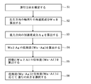
- FIG. 7 is a flowchart for explaining processing performed by the moving body traveling direction estimation apparatus according to the first embodiment of the present invention to estimate the traveling direction.
- step S500 basic data calculation processing necessary as preprocessing for processing for estimating the traveling direction is performed. Details will be described later with reference to FIG.
- the provisional traveling direction vector generation unit 2413 is given a resolution to be estimated (for example, 0.5 degree unit) and a gravity direction vector, and based on that, generates a traveling direction vector candidate orthogonal to the gravity direction vector at the resolution step.
- One of the candidates (provisional travel direction vector) is output in order (step S501).
- the traveling direction vector projection calculation unit 2417 projects the angular velocity vector (three axes) onto the provisional traveling direction vector obtained in S501 and acquires the magnitude of the component (step S502).
- the projected component is stored in the buffer 2433 and then converted into data on the frequency domain by the one-dimensional FFT operation unit 2422.
- the traveling direction vector determination unit 2425 obtains the power value P3 and the phase H3 of the frequency component of the walking frequency f0 ⁇ 1/2 based on the data after the one-dimensional discrete Fourier transform calculation process calculated in step S502 (step S503). ). Note that the walking frequency f0 is calculated in step S500, which is pre-processing, and uses that value.
- the traveling direction vector projection calculation unit 2418 projects the angular velocity vector onto the left / right direction vector (pitch axis) obtained by the cross product operation of the provisional traveling direction vector and the gravity direction vector, and determines the magnitude of the component (step S504). Further, the projected component is stored in the buffer 2434, and then the one-dimensional FFT calculation unit 2423 executes a one-dimensional discrete Fourier transform calculation process to convert data into the frequency domain.
- the traveling direction vector determination unit 2425 acquires the walking frequency f0 calculated in step S500 based on the one-dimensional discrete Fourier transform data converted in step S504, and the power value P4 and phase H4 of the frequency component of the walking frequency. Is obtained (step S505).
- the traveling direction vector projection calculation unit 2415 projects the acceleration vector (three axes) onto the provisional traveling direction vector given in step S501, and obtains the magnitude of the component (step S506). After the projected component is stored in the buffer 2431, the one-dimensional FFT calculation unit 2420 executes a one-dimensional discrete Fourier transform calculation process to convert data into the frequency domain.
- the traveling direction vector determination unit 2425 obtains the power value P1 and the phase H1 of the frequency component of the walking frequency based on the walking frequency calculated in step S500 based on the one-dimensional discrete Fourier transform data converted in step S506 ( Step S507). When a sufficiently high peak value is not included in this range, it may be considered that no walking motion has been detected and this process may be skipped.
- the left / right direction vector projection calculation unit 2416 projects the acceleration vector (three axes) to the left / right direction vector (pitch axis) obtained by the cross product calculation of the provisional traveling direction vector and the gravity direction vector given in step S501. Then, the size of the component is obtained (step S508).
- the projected component is stored in the buffer 2432, and then the one-dimensional FFT calculation unit 2421 executes a one-dimensional discrete Fourier transform calculation process to convert the data into the frequency domain.
- the traveling direction vector determination unit 2425 uses the walking frequency calculated in step S500 and the power value P2 and phase of the frequency component of walking frequency ⁇ 1/2. H2 is obtained (step S509).
- the traveling direction vector determination unit 2425 calculates an objective function U (P1, P2, P3, P4) using the respective power values obtained in Step S503, Step S505, Step S507, and Step S509 as arguments (Step S510).
- U (P1, P2, P3, P4) w1P1 + w2P2 + w3P3 + w4P4 can be considered.
- the combination is not limited to these weighting factors.
- the traveling direction vector determination unit 2425 obtains a phase difference H1-H0 between the phase H1 obtained in step S507 and the phase H0 obtained in step S500, and tests whether this phase difference is within a certain range (step S511). ). Only when this phase difference falls within a certain range, it is determined that the provisional travel direction vector given in step S501 is acceptable as a candidate.
- a specific value of the range of the phase difference a numerical value recorded in an external storage device may be used.
- the range of the phase difference is, for example, a range of 0 degrees to 100 degrees.
- the traveling direction vector determination unit 2425 advances the process to step S513 when the provisional traveling direction vector generated and output in step S501 covers all combinations with the target resolution, and otherwise proceeds to step S501.
- Advance step S512
- the process proceeds to step S513, and otherwise, the process proceeds to step S501.
- the traveling direction vector determination unit 2425 selects the tentative traveling direction vectors of all the combinations that have passed the phase difference test in step S511, and selects the one that maximizes the objective function U and determines it as the traveling direction vector (step S513).
- two traveling direction vectors having the correct traveling direction and 180 degrees opposite thereto are determined.
- the traveling direction vector determination unit 2425 simply determines that the traveling direction selection unit 16 shown in FIG. 6 determines the direction in which the power spectrum of the acceleration component Af in the temporary traveling direction is the maximum as the correct traveling direction.
- An embodiment in which the traveling direction vector is determined by various methods is also conceivable.
- the angular velocity component Ws around the axis in the traveling direction is Fourier transformed by the discrete Fourier transform unit 10, and the power spectrum for each frequency component is supplied to the angular velocity component (Ws) generation unit 15.
- the angular velocity component (Ws) generation unit 15 calculates a component for each traveling direction temporarily determined by the provisional traveling direction vector generation unit 2413.
- the traveling direction selection unit 16 determines the correct traveling direction in consideration of the direction in which the power spectrum of the angular velocity component Ws around the traveling direction axis is maximized.
- the traveling direction selection unit 16 can estimate the traveling direction with the highest accuracy by using both the acceleration component Af and the angular velocity component Ws, but only one of the components is used. By doing so, the traveling direction can be estimated.
- FIG. 8 is a flowchart for explaining the breakdown of the processing in step S500 in FIG.
- This step S500 comprises sub-steps S5101 to S5104, the contents of which are as follows.
- the gravity direction vector estimation unit 2407 receives the acceleration vector and the angular velocity vector as input, and calculates a gravity direction vector (step S5101).
- Gravity direction vector projection calculation unit 2414 projects the motion acceleration vector (obtained by removing the gravitational acceleration vector from the acceleration vector) onto the gravity direction vector obtained in step S5101, and obtains the magnitude of the component ( Step S5102).
- the component obtained in step S5102 is stored in the buffer 2430 (step S5103).
- the one-dimensional FFT operation unit 2419 applies a one-dimensional discrete Fourier transform operation process to the data string stored in step S5103, and outputs discrete Fourier transform data converted on the frequency domain (step S5104).
- the walking frequency estimation unit 2424 takes the peak frequency component based on the discrete Fourier transform data obtained in step S5104 and obtains the walking frequency f0 (step S5105).
- the traveling direction estimation apparatus estimates the traveling direction by the method shown in FIG. 7 in step S1.
- this traveling direction estimation apparatus determines the direction (front and back) of the estimated traveling directions by the following method.
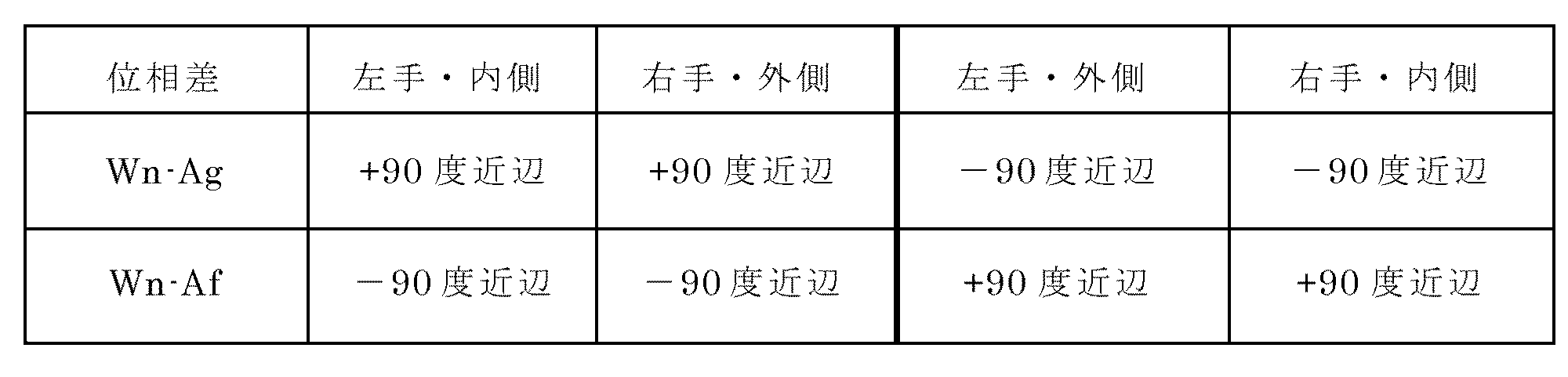
- human characteristics as shown in Table 2 are used.
- Table 2 when this traveling direction estimation device is gripped by the hand of a person walking while swinging his / her arm, the left and right and left / right directions of the gripped hand, that is, the left / right direction is the pedestrian.
- Table 2 when this traveling direction estimation device is gripped by the hand of a person walking while swinging his / her arm, the left and right and left / right directions of the gripped hand, that is, the left / right direction is the pedestrian.
- the present travel direction estimation device when the present travel direction estimation device is gripped by the left hand and the left and right direction is facing outward, the present travel direction estimation device is when the right hand is gripped and the left and right direction is facing inward. Since it is placed in two places that travel parallel in space, the characteristics of the phase difference (Wn-Ag) and phase difference (Wn-Af) match ( Hereinafter referred to as “second state”).
- FIG. 10 is a graph showing the phase relationship between the angular velocity component Wn and the acceleration components Ag and Af in this case.
- the horizontal axis represents time (seconds)
- the vertical axis represents unitless power.
- the phase of the angular velocity component Wn is approximately 90 degrees ahead of the acceleration component Ag, and the phase is delayed by approximately 90 degrees in relation to the acceleration component Af.
- phase difference (Wn-Ag) and the phase difference (Wn-Af) are different between the first state and the second state, at least one of them is calculated and the magnitude thereof is the value shown in Table 2. By illuminating, it is possible to determine in which state the traveling direction estimation device is.
- the traveling direction can be estimated, it is possible to estimate the traveling direction of the traveling body such as a person having the traveling direction estimation device by determining the first and second states. Obviously, it is possible to estimate the traveling direction of the traveling body such as a person having the traveling direction estimation device by determining the first and second states. Obviously, it is possible to estimate the traveling direction of the traveling body such as a person having the traveling direction estimation device by determining the first and second states. Obviously, it is possible to estimate the traveling direction of the traveling body such as a person having the traveling direction estimation device by determining the first and second states. Become.
- step S2 the travel direction estimation apparatus calculates an angular velocity component Wn around the left-right axis of the travel direction estimation apparatus.
- the angular velocity component Wn around the horizontal axis is calculated by the horizontal vector Wn projection calculation unit 2418 based on the magnitude of the angular velocity sensed by the angular velocity sensor.
- An example of the power spectrum of the calculated angular velocity component Wn around the horizontal axis as described above is shown in FIG.
- the traveling direction estimation apparatus calculates an acceleration component Ag in the gravity direction in step S3.
- the gravity direction vector Ag projection calculation unit 2414 calculates the acceleration component Ag in the gravity direction based on the magnitude of the acceleration sensed by the acceleration sensor and the gravity direction vector estimated by the gravity direction vector estimation unit 2407. .
- the gravity direction vector estimation unit 2407 estimates the gravity direction based on data obtained by the angular velocity sensor and the acceleration sensor. Further, as described above, an example of the power spectrum of the acceleration component Ag in the gravity direction calculated by the gravity direction vector Ag projection calculation unit 2414 is shown in FIG.
- the traveling direction estimation apparatus calculates a phase difference (Wn ⁇ Ag) between the angular velocity component Wn around the left and right axis and the angular velocity component Ag around the gravity axis.
- the phase difference (Wn ⁇ Ag) is the angular velocity component Wn around the horizontal axis calculated by the horizontal vector Wn projection calculation unit 2418 and the gravity axis calculated by the gravity direction vector Ag projection calculation unit 2414. Is calculated by a phase difference (Wn-Ag) calculating unit 2435 based on the acceleration component Ag.
- the traveling direction estimation device calculates a phase difference (Wn ⁇ Af) between the angular velocity component Wn around the left-right axis and the acceleration component Af around the traveling-direction axis.
- the phase difference (Wn ⁇ Af) is determined by the angular velocity component Wn around the horizontal axis calculated by the horizontal vector Wn projection calculation unit 2418 and the traveling direction obtained by the acceleration component (Af) generation unit 14.
- the phase difference (Wn ⁇ Af) calculation unit 2436 calculates the phase difference.
- the traveling direction estimation apparatus calculates the phase difference (Wn-Ag) and the phase difference (Wn-Af) calculated by the phase difference (Wn-Ag) calculation unit 2435 by the front-rear direction determination unit 17 in step S6.
- the progress estimation device determines which of the first state and the second state It is determined whether it has a state, and the front-rear direction is determined.
- the front-rear direction determination unit 17 estimates the front-rear direction more reliably when using either the phase difference (Wn-Ag) or the phase difference (Wn-Af) than when using either one. can do.
- the traveling direction determination unit 18 estimates the traveling direction and its direction according to the traveling direction selected by the traveling direction selection unit 16 and the front-rear direction estimated by the front-rear determination direction determination unit 17.
- the traveling direction estimation device according to the embodiment of the present invention, it is possible to estimate not only the traveling direction of a moving body such as a person having the traveling direction estimation device but also the direction thereof with high accuracy. .
- FIG. 11 is a functional block diagram for explaining the basic configuration of the moving body travel direction estimating apparatus according to the second embodiment of the present invention.
- acceleration sensors three axes
- angular velocity sensors three axes
- 2506 have a total of six sensing means in the orthogonal coordinate system. These outputs do not need to be raw data of each sensor, and may be data after being properly calibrated.
- the gravity direction vector estimation unit 2513 receives the acceleration vector (three axes) measured by the acceleration sensor and the angular velocity vector (three axes) measured by the angular velocity sensor, and estimates and outputs the gravity direction vector.
- the gravity direction vector here is a unit vector, the magnitude of gravitational acceleration can be said to be known in principle, so that the gravitational acceleration vector can be calculated simultaneously. Therefore, by storing the result of removing the gravitational acceleration vector from the output of the acceleration sensor in the buffer, the motion acceleration vector of the moving body can be stored in the buffer of each axis.
- the buffer 2507 receives the acceleration component (X axis) output and the gravitational acceleration vector (X axis component), and stores the acceleration component obtained by removing the gravitational acceleration vector (X axis component) from the acceleration component (X axis).
- the buffer 2508 receives the acceleration component (Y axis) output and the gravitational acceleration vector (Y axis component), and stores the acceleration component obtained by removing the gravitational acceleration vector (Y axis component) from the acceleration component (Y axis).
- the The buffer 2509 receives the acceleration component (Z-axis) output and the gravitational acceleration vector (Z-axis component), and stores the acceleration component obtained by removing the gravitational acceleration vector (Z-axis component) from the acceleration component (Z-axis).
- the buffer 2510 stores the angular velocity component (X axis).
- the buffer 2511 stores the angular velocity component (Y axis).
- the buffer 2512 stores the angular velocity component (Z axis).
- the one-dimensional FFT calculation unit 2531 receives the data sequence obtained from the buffer 2507 storing the motion acceleration component (X axis) and applies the one-dimensional FFT calculation processing to convert the FFT data converted into the frequency domain. Find and output.
- the one-dimensional FFT calculation unit 2532 receives the data string obtained from the buffer 2508 storing the motion acceleration component (Y axis) and applies the one-dimensional FFT calculation processing to convert the FFT data converted into the frequency domain. Find and output.
- the one-dimensional FFT operation unit 2533 receives the data sequence obtained from the buffer 2509 storing the motion acceleration component (Z-axis) as input and applies the one-dimensional FFT operation processing to the FFT data converted into the frequency domain. Find and output.
- the one-dimensional FFT calculation unit 2534 receives the data sequence obtained from the buffer 2510 storing the angular velocity component (X axis) and applies the one-dimensional FFT calculation processing to obtain FFT data converted into the frequency domain. ,Output.
- the one-dimensional FFT operation unit 2535 receives the data string obtained from the buffer 2511 storing the angular velocity component (Y axis) and applies the one-dimensional FFT operation processing to obtain FFT data converted into the frequency domain. ,Output.
- the one-dimensional FFT operation unit 2536 receives the data string obtained from the buffer 2512 storing the angular velocity component (Z-axis) and applies one-dimensional FFT operation processing to obtain FFT data converted into the frequency domain. ,Output.
- Gravity direction vector projection calculation unit 2515 receives the acceleration component of acceleration sensor 2501, 2502, 2503 that outputs the gravity direction vector output by gravity direction vector estimation unit 2513 and the acceleration component (three axes) as input. The projection component of the acceleration vector onto the gravity direction vector is obtained and output. This output is stored in buffer 2530.
- the projection component of the motion acceleration vector stored in the buffer 2530 to the gravity direction vector is converted into FFT data on the frequency domain by the one-dimensional FFT calculation unit 2519 and output.
- the walking frequency estimation unit 2524 estimates the fundamental frequency of walking motion based on the FFT data output from the one-dimensional FFT calculation unit 2519. This estimation method may be the same as the method shown in the previous embodiment.
- the provisional travel direction vector generation unit 2514 receives as input the gravity direction vector output from the gravity direction vector estimation unit 2513, and comprehensively generates and outputs a group of travel direction vector candidates orthogonal to the gravity direction vector. This generation method is the same as the method shown in the previous embodiment.
- Advancing direction vector projection FFT calculator 2537 includes each of the advancing direction vector generated and output by the advancing direction vector generating unit 2514 and the motion acceleration vector output by the one-dimensional FFT calculating units 2531, 2532, and 2533. Using the component FFT data as input, calculate and output the FFT data of the component obtained by projecting the motion acceleration vector to the provisional travel direction vector. Note that such a calculation can be justified only when it is assumed that the traveling direction vector does not change during the sampling time of the FFT, and is actually an approximate calculation. The number of one-dimensional FFT operations can be greatly reduced.
- the left-right direction vector projection FFT calculation unit 2538 includes components of the left-right direction vector generated and output by the provisional travel direction vector generation unit 2514 and the motion acceleration vector output by the one-dimensional FFT calculation units 2531, 2532, and 2533.
- the FFT data of the component obtained by projecting the motion acceleration vector to the left-right direction vector (pitch axis) is calculated and output.
- the traveling direction vector projection FFT calculation unit 2539 is a component of the temporary traveling direction vector generated and output by the temporary traveling direction vector generation unit 2514 and the angular velocity vector output by the one-dimensional FFT calculation units 2534, 2535, and 2536.
- the FFT data of the component obtained by projecting the angular velocity vector into the traveling direction vector is calculated and output.
- the left-right direction vector projection FFT calculation unit 2540 includes the left-right direction vector generated and output by the provisional traveling direction vector generation unit 2514 and the angular velocity vector components output by the one-dimensional FFT calculation units 2534, 2535, and 2536. Using the FFT data as input, calculate and output the FFT data of the component obtained by projecting the angular velocity vector to the left-right direction vector (pitch axis).
- the phase difference (Wn-Ag) calculation unit 2542 is a Fourier transform 1 of the output of the (angular velocity component) left-right direction vector Wn projection FFT calculation unit 2540 and the result calculated by the (acceleration component) gravity direction vector Ag projection calculation unit 2515. Based on the output of the dimension FFT calculation unit 2519, the phase difference between the angular velocity component Wn in the left-right direction and the acceleration component Ag in the gravity direction is calculated.
- the phase difference (Wn-Af) calculation unit 2543 is based on the output of the (angular velocity component) left-right direction vector Wn projection FFT calculation unit 2540 and the output of the (acceleration component) travel direction vector Af projection FFT calculation unit 2537.
- the phase difference between the angular velocity component Wn and the acceleration component Af in the traveling direction is calculated.
- the traveling direction vector determination unit 2541 includes the walking frequency output from the walking frequency estimation unit 2524, (acceleration component) traveling direction vector projection FFT calculation unit 2537, (acceleration component) left / right direction vector projection FFT calculation unit 2538, (angular velocity component) This is an element that determines and outputs the traveling direction vector with four FFT data of the traveling direction vector projection FFT calculation unit 2539 and the (angular velocity component) left and right direction vector projection FFT calculation unit 2540 as inputs.
- the determination method is the same as that of the first embodiment because it is obtained from the walking frequency and the FFT data (four).
- FIG. 12 is a flowchart for explaining processing performed by the moving body traveling direction estimation apparatus according to the second embodiment of the present invention to estimate the traveling direction.
- calculation processing of basic data necessary as preprocessing of processing performed to estimate the traveling direction is performed (step S600).
- the details are the same as those in FIG. 4 in the first embodiment, and a description thereof will be omitted.
- the provisional traveling direction vector generation unit 2514 is given a resolution to be estimated (for example, 0.5 degree unit) and a gravity direction vector, and based on that, generates a group of candidate traveling direction vectors orthogonal to the gravity direction vector in increments of the resolution.
- One of the candidates (provisional travel direction vector) is exhaustively output in order (step S601).
- Angular velocity component In the traveling direction vector projection FFT calculation unit 2539, FFT data obtained by transforming the component projected onto the temporary traveling direction vector of the angular velocity vector into the frequency domain is converted into linear one-dimensional FFT calculation of each component of the angular velocity vector. Obtained by combination (step S602). FFT data of each component of the temporary travel direction vector generated and output by the temporary travel direction vector generation unit 2514 and the angular velocity vector output by the one-dimensional FFT calculation units 2534, 2535, and 2536 is calculated as an input.
- the Fourier transform of the angular velocity component obtained by projecting the angular velocity vector onto the provisional traveling direction vector is represented by each component of the angular velocity vector (X / Y / Z Obtained by linear combination of the Fourier transform of the axis. That is, the angular velocity component represented by the following formula Is the linear combination of the Fourier transform of the X / Y / Z-axis components of the angular velocity vector Obtained by.
- the traveling direction vector when the traveling direction vector can be regarded as not changing for the sample time length taken by the FFT calculation, the FFT data of the projection component can be obtained by linear combination of the one-dimensional FFT data of each component. Actually, since the traveling direction vector does not change at all with respect to the time of the sample time length, this is only an approximate calculation, but the number of FFT operations can be greatly reduced.
- the traveling direction vector determination unit 2541 obtains the power value and phase of the frequency component of the walking frequency ⁇ 1/2 for the FFT data obtained in step S602 (step S603).
- Left-right direction vector projection FFT calculation unit 2540 converts the FFT of the component projected onto the left-right direction vector (pitch axis) of the angular velocity vector into the frequency domain, and a one-dimensional FFT of each component of the angular velocity vector. Obtained by linear combination of operations (step S604).
- the calculation method is the same as the angular velocity component traveling direction vector projection FFT calculation.
- the traveling direction vector determination unit 2541 obtains the power value and phase of the frequency component of the walking frequency for the FFT data obtained in step S604 (step S605).
- acceleration component In the traveling direction vector projection FFT calculation unit 2537, FFT data obtained by converting the component projected onto the temporary traveling direction vector of the acceleration vector into the frequency domain is linearly converted into a one-dimensional FFT calculation of each component of the acceleration vector. Obtained by combination (step S606). For example, when a provisional travel direction vector (d x , dy , d z ) is given, the Fourier transform of the acceleration component obtained by projecting the acceleration vector onto the provisional travel direction vector is expressed as each component of the acceleration vector (X / Y / Z Obtained by linear combination of the Fourier transform of the axis. That is, the acceleration component represented by the following formula Is the linear combination of the Fourier transform of the X / Y / Z axis components of the acceleration vector Obtained by.
- the traveling direction vector determination unit 2541 obtains the power value and phase of the frequency component of the walking frequency for the FFT data obtained in step S606 (step S607).
- Left-right direction vector projection FFT calculation unit 2538 generates FFT data obtained by converting the component projected onto the left-right direction vector (pitch axis) of the acceleration vector into the frequency domain, and a one-dimensional FFT of each component of the acceleration vector. Obtained by linear combination of operations (step S608).
- the calculation method is the same as the acceleration component traveling direction vector projection FFT calculation.
- the traveling direction vector determination unit 2541 obtains the power value and phase of the frequency component of walking frequency ⁇ 1/2 for the FFT data obtained in step S608 (step S609).
- the traveling direction vector determination unit 2541 calculates the value of the objective function based on the power values obtained in steps S603, S605, S607, and S609 by the same method as in the previous embodiment (step S610).
- the traveling direction vector determination unit 2541 checks that the phase difference between the phase obtained in step S607 and the phase of the projection component of the acceleration vector obtained in step S600 to the gravity direction vector is within a certain range. (Step S611).
- the traveling direction vector determination unit 2425 advances the process to step S613 when the process has been executed for all the temporary moving direction vectors, and advances the process to step S601 otherwise (step S612).
- the traveling direction vector determination unit 2541 outputs two vectors whose directions are opposite to each other as the final traveling direction vector, from among the candidates for the traveling direction vector that have passed the inspection in step S611, those that maximize the objective function U. (Step S613).
- the result of the discrete Fourier transform (DFT) in that period can be expressed by a linear combination of the discrete Fourier transform of each component in the sensor coordinate system. .
- DFT discrete Fourier transform
- the discrete Fourier transform is executed for each of the three axes of the acceleration vector and the angular velocity vector (X / Y / Z axis) in the sensor coordinate system, and immediately before the discrete Fourier transform is applied.
- the result of Fourier transform of the linear combination of the acceleration vector and the gravity direction vector matches the linear combination of the result of Fourier transform of each component of the acceleration vector and the gravity direction vector. It is.
- the result of Fourier transform of the linear combination of the angular velocity vector and the gravity direction vector coincides with the linear combination of the result of Fourier transform of each component of the angular velocity vector and the gravity direction vector.
- the number of discrete Fourier transform processing required for the processing is different for each component of the acceleration vector (X / Y / Z axis) and each of the angular velocity vectors. Since it is only applied to the component (X / Y / Z axis), the total is 6 times, which can be greatly reduced.
- the traveling direction vector determination unit 2541 uses the same method as the traveling direction vector determination unit 2425 according to the first embodiment, and the traveling direction vector determination unit 2541 outputs the two traveling direction vectors whose directions are opposite to each other output in step S613. A vector indicating the traveling direction of the moving body can be selected.
- the traveling direction estimation device and the traveling direction estimation method according to the embodiment of the present invention are not limited to being held by the hand of a person walking while swinging an arm, but are placed in the pockets of the lower limbs of the person walking Even in the case of being put in the handbag of a walking person or the like, the effects of the present invention can be obtained because of the characteristics shown in Table 2 above.
Landscapes
- Engineering & Computer Science (AREA)
- Radar, Positioning & Navigation (AREA)
- Remote Sensing (AREA)
- Physics & Mathematics (AREA)
- General Physics & Mathematics (AREA)
- Automation & Control Theory (AREA)
- Navigation (AREA)
- Indicating Or Recording The Presence, Absence, Or Direction Of Movement (AREA)
- Traffic Control Systems (AREA)
- Measurement Of Distances Traversed On The Ground (AREA)
- Measurement Of The Respiration, Hearing Ability, Form, And Blood Characteristics Of Living Organisms (AREA)
Description
上記(1)~(3)のベクトルについて推定(トラッキング)することで、水平基準方向に対する進行方向のなす角の推定がなされ、歩行者の移動方位角の推定を行うことが可能となる。
また、(2)の水平基準方向ベクトルは、加速度センサ、角速度センサ、磁気センサに基づいて水平基準方向のトラッキングを行うことが可能である。
例えば、非特許文献1には、重力方位ベクトル及び水平基準方向ベクトルのトラッキングを行う手法が具体的に開示されている。また、いわゆるAHRS(Attitude and Heading Reference System)に基づく手法も知られている。

本発明は、このような問題を解決するためになされたもので、移動体の進行方向を精度よく推定することのできる装置及び方法を提供することを目的とする。
以下、本発明を実施するための第一の実施の形態について、図面を参照して説明する。
図1は、本発明の第一の実施の形態に係る移動体の進行方向推定装置の基本的な構成を説明する機能ブロック図である。


本進行方向推定装置は、ステップS2において、本進行方向推定装置が有する左右方向の軸周りの角速度成分Wnを算出する。ここで、左右方向の軸周りの角速度成分Wnは、角速度センサによりセンシングされた角速度の大きさに基づいて左右方向ベクトルWn射影計算部2418により算出される。なお、上記のように、算出された左右方向の軸周りの角速度成分Wnのパワースペクトラムの例が図5に示される。
以上より、本発明の実施の形態に係る進行方向推定装置によれば、本進行方向推定装置を持った人等の移動体の進行方向のみならず、その向きまで高精度に推定することができる。
次に本発明の第二の実施の形態について説明する。本発明の第二の実施の形態においては、ある一定期間(例えば、128サンプル分=1.28秒、100Hzの場合)に進行方向が変化していないとみなすことで離散フーリエ変換にかかる計算コストを低減するものである。なお、本実施の形態において、第一の実施の形態と同様の構成にかかる部分については説明を省略する。




11 離散フーリエ変換部(加速度3軸分)
16 進行方向選択部
17 前後方向決定部
18 進行方向決定部
2401、2402、2403 加速度成分
2404、2405、2406 角速度成分
2407 重力方向ベクトル推定部
2413 仮進行方向ベクトル生成部
2414 (加速度成分)重力方向ベクトル射影計算部
2415 (加速度成分)進行方向ベクトル射影計算部
2416 (加速度成分)左右方向ベクトル射影計算部
2417 (角速度成分)進行方向ベクトル射影計算部
2418 (角速度成分)左右方向ベクトル射影計算部
2430~2434 バッファ
2419~2423 1次元FFT演算部
2424 歩行周波数推定部
2425 進行方向ベクトル決定部
2435,2542 位相差(Wn-Ag)算出部
2436,2543 位相差(Wn-Af)算出部
Claims (14)
- 移動体の進行方向を推定する進行方向推定装置であって、
移動体の加速度ベクトル成分データを計測する加速度計測部と、
移動体の角速度ベクトル成分データを計測する角速度計測部と、
前記加速度ベクトル成分データ及び前記角速度ベクトル成分データに基づいて、移動体の重力方向ベクトルを推定する重力方向ベクトル推定部と、
前記重力方向ベクトル推定部が出力した重力方向ベクトルに基づいて仮進行方向ベクトル及び左右方向ベクトルを生成する仮進行方向ベクトル生成部と、
前記加速度成分データから前記重力方向ベクトルを除いた後の加速度ベクトル成分データを重力方向ベクトルに射影した成分データを算出し、その周波数領域成分を出力することで歩行周波数とその周波数成分の位相を求める歩行周波数算定部と、
前記仮進行方向ベクトルと、前記重力方向ベクトルと、前記加速度ベクトル成分データに基づいて、前記加速度ベクトル成分データから重力加速度ベクトルを除いた後の加速度ベクトル成分データを仮進行方向ベクトルに射影した成分データを算出し、その周波数領域成分を出力する演算部と、
前記重力方向ベクトルと、前記左右方向ベクトルと、前記加速度ベクトル成分データに基づいて、前記加速度ベクトル成分データから重力加速度ベクトルを除いた後の加速度ベクトル成分データを、前記左右方向ベクトルに射影した成分データを算出し、その周波数領域成分を出力する演算部と、
前記仮進行方向ベクトルと、前記角速度ベクトル成分データに基づいて、前記角速度ベクトル成分データを前記仮進行方向ベクトル上に射影した成分を算出し、その周波数領域成分を出力する演算部と、
前記左右方向ベクトルと、前記角速度ベクトル成分データに基づいて、前記角速度ベクトル成分データを前記左右方向ベクトル上に射影した成分を算出し、その周波数領域成分を出力する演算部と、
前記歩行周波数と、前記加速度成分進行方向ベクトルの射影した周波数領域成分と、前記加速度成分左右方向ベクトルの射影した周波数領域成分と、前記角速度進行方向ベクトルの射影した周波数領域成分と、前記角速度左右方向ベクトルの射影した周波数領域成分と、に基づいて歩行周波数の周波数成分又は歩行周波数の1/2の周波数成分からパワー値を算出することで、目的関数を求め、前記加速度成分進行方向ベクトルの射影した周波数領域成分から、歩行周波数の周波数成分の位相と算出して、前記歩行周波数算定部が算定した歩行周波数の位相との位相差をもとめ、前記位相差が所定範囲内の場合に、目的関数の値を取る仮進行方向ベクトルを候補とし、候補となった仮進行方向ベクトルのうち、目的関数の値が最大となる仮進行方向ベクトルを進行方向ベクトルとして出力する進行方向ベクトル決定部と、を有する進行方向推定装置。 - 前記歩行周波数算定部は、前記加速度成分データから前記重力方向ベクトルを除いた後の加速度ベクトル成分データを重力方向ベクトルに射影した成分データを算出する加速度成分重力方向ベクトル射影計算部と、
前記加速度成分データを重力方向ベクトルに射影した成分データに1次元離散フーリエ変換演算を適用して、周波数領域成分を出力する1次元離散フーリエ変換演算部と、
1次元離散フーリエ変換演算部の出力に基づいて、歩行動作の基本周波数とその周波数成分の位相を求める歩行周波数算定部とを有することを特徴とする請求項1記載の進行方向推定装置。 - 前記加速度成分進行方向ベクトルの射影した周波数領域成分を出力する演算部は、加速度ベクトル成分データから重力加速度ベクトルを除いた後の加速度ベクトル成分データを仮進行方向ベクトルに射影した成分を計算する加速度成分進行方向ベクトル射影計算部と、前記加速度成分進行方向ベクトル射影計算部が出力した加速度成分に1次元離散フーリエ変換演算を行って周波数領域成分を出力する1次元離散フーリエ変換演算部とを有し、前記加速度成分左右方向ベクトルの射影した周波数領域成分を出力する演算部は、前記重力方向ベクトルと、前記左右方向ベクトルと、前記加速度ベクトル成分データに基づいて、前記加速度ベクトル成分データから重力加速度ベクトルを除いた後の加速度ベクトル成分データを、前記左右方向ベクトルに射影した成分データを算出する加速度成分左右方向ベクトル射影計算部と、前記加速度成分左右方向ベクトル射影計算部が出力した加速度成分に1次元離散フーリエ変換演算を行って周波数領域成分を出力する1次元離散フーリエ変換演算部とを有し、
前記角速度進行方向ベクトルの射影した周波数領域成分を出力する演算部は、前記仮進行方向ベクトルと、前記角速度ベクトル成分データに基づいて、前記角速度ベクトル成分データを前記仮進行方向ベクトル上に射影した成分を算出する角速度成分進行方向ベクトル射影計算部と、前記角速度成分進行方向ベクトル射影計算部が出力した角速度成分に1次元離散フーリエ変換演算を行って周波数領域成分を出力する1次元離散フーリエ変換演算部とを有し、前記角速度左右方向ベクトルの射影した周波数領域成分を出力する演算部は、前記左右方向ベクトルと、前記角速度ベクトル成分データに基づいて、前記角速度ベクトル成分データを前記左右方向ベクトル上に射影した成分を算出する角速度成分左右方向ベクトル射影計算部と、前記角速度左右方向ベクトル射影計算部が出力した角速度成分に1次元離散フーリエ変換演算を行って周波数領域成分を出力する1次元離散フーリエ変換演算部とを有する、請求項1または2記載の進行方向推定装置。 - 前記加速度成分進行方向ベクトルの射影した周波数領域成分を出力する演算部は、加速度ベクトル成分データの各々から重力加速度ベクトルを除去した加速度成分に1次元離散フーリエ変換演算を行って出力されたそれぞれの周波数領域成分データと、仮進行方向ベクトルとの線形結合を算出して1次元離散フーリエ変換を行う加速度成分進行方向ベクトル射影離散フーリエ変換計算部であり、
前記加速度成分左右方向ベクトルの射影した周波数領域成分を出力する演算部は、加速度ベクトル成分データの各々から重力加速度ベクトルを除去した加速度成分に1次元離散フーリエ変換演算を行って出力されたそれぞれの周波数領域成分データと、前記左右方向ベクトルとの線形結合を算出して1次元離散フーリエ変換を行う加速度成分左右方向ベクトル射影離散フーリエ変換計算部であり、
前記角速度進行方向ベクトルの射影した周波数領域成分を出力する演算部は、角速度ベクトル成分データの各々に1次元離散フーリエ変換演算を行って出力されたそれぞれの周波数領域成分データと、前記仮進行方向ベクトルとの線形結合を算出して1次元離散フーリエ変換を行う角速度成分進行方向ベクトル射影離散フーリエ変換計算部であり、
前記角速度左右方向ベクトルの射影した周波数領域成分を出力する演算部は、角速度ベクトル成分データの各々に1次元離散フーリエ変換演算を行って出力されたそれぞれの周波数領域成分データと、前記左右方向ベクトルとの線形結合を算出して1次元離散フーリエ変換を行う角速度成分左右方向ベクトル射影離散フーリエ変換計算部である、請求項1又は2記載の進行方向推定装置。 - 前記角速度ベクトル成分データを前記左右方向ベクトル上に射影した成分と、前記加速度ベクトル成分データを重力方向ベクトルに射影した成分データ及び前記加速度ベクトル成分データを仮進行方向ベクトルに射影した成分データのうち少なくとも一方との間の位相差を算出する位相差算出手段と、
前記位相差算出手段で算出された少なくとも一つの位相差に応じて、前記進行方向ベクトル決定部により出力された向きが逆の二つの前記進行方向ベクトルのうち前記移動体の進行の向きを示すいずれか一つのベクトルを選択する進行方向選択手段とをさらに備えた請求項1に記載の進行方向推定装置。 - 前記角速度ベクトル成分データを前記左右方向ベクトル上に射影した成分と前記加速度ベクトル成分データを重力方向ベクトルに射影した成分データとの間の第一の位相差を算出する第一位相差算出手段と、
前記角速度ベクトル成分データを前記左右方向ベクトル上に射影した成分と前記加速度ベクトル成分データを仮進行方向ベクトルに射影した成分データとの間の第二の位相差を算出する第二位相差算出手段と、
前記第一及び第二の位相差に応じて、前記進行方向ベクトル決定部により出力された向きが逆の二つの前記進行方向ベクトルのうち前記移動体の進行の向きを示すいずれか一つのベクトルを選択する進行方向選択手段とをさらに備えた請求項1に記載の進行方向推定装置。 - 前記進行方向選択手段は、
前記二つの前記進行方向ベクトルの各向きに応じた前記第一及び第二の位相差を基準データとして予め取得し、第一位相差算出手段で算出された前記第一の位相差と前記第二位相差算出手段で算出された前記第二の位相差を前記基準データと比較する請求項6に記載の進行方向推定装置。 - 移動体の進行方向を推定するための進行方向推定方法であって、
移動体の加速度ベクトル成分データ及び角速度ベクトル成分データを計測する第一のステップと、
前記第一のステップで計測された前記加速度ベクトル成分データ及び前記角速度ベクトル成分データに基づいて、移動体の重力方向ベクトルを推定する第二のステップと、
前記第二のステップで推定された重力方向ベクトルに基づいて仮進行方向ベクトル及び左右方向ベクトルを生成する第三のステップと、
前記第一のステップで計測された前記加速度ベクトル成分データから前記第二のステップで推定された前記重力方向ベクトルを除いた後の加速度ベクトル成分データを重力方向ベクトルに射影した成分データを算出し、その周波数領域成分を出力することで歩行周波数とその周波数成分の位相を求める第四のステップと、
前記第三のステップで生成された前記仮進行方向ベクトルと、前記第二のステップで推定された前記重力方向ベクトルと、前記第一のステップで計測された前記加速度ベクトル成分データに基づいて、前記加速度ベクトル成分データから重力加速度ベクトルを除いた後の加速度ベクトル成分データを仮進行方向ベクトルに射影した成分データを算出し、その周波数領域成分を求める第五のステップと、
前記第二のステップで推定された前記重力方向ベクトルと、前記第三のステップで生成された前記左右方向ベクトルと、前記第一のステップで計測された前記加速度ベクトル成分データに基づいて、前記加速度ベクトル成分データから重力加速度ベクトルを除いた後の加速度ベクトル成分データを、前記左右方向ベクトルに射影した成分データを算出し、その周波数領域成分を求める第六のステップと、
前記第三のステップで生成された前記仮進行方向ベクトルと、前記第一のステップで計測された前記角速度ベクトル成分データに基づいて、前記角速度ベクトル成分データを前記仮進行方向ベクトル上に射影した成分を算出し、その周波数領域成分を求める第七のステップと、
前記第三のステップで生成された前記左右方向ベクトルと、前記第一のステップで計測された前記角速度ベクトル成分データに基づいて、前記角速度ベクトル成分データを前記左右方向ベクトル上に射影した成分を算出し、その周波数領域成分を求める第八のステップと、
前記第四のステップで求められた前記歩行周波数と、前記第五のステップで求められた前記加速度ベクトル成分データの仮進行方向ベクトル上に射影した周波数領域成分と、前記第六のステップで求められた前記加速度ベクトル成分データの左右方向ベクトル上に射影した周波数領域成分と、前記第七のステップで求められた前記角速度ベクトル成分データの仮進行方向ベクトル上に射影した周波数領域成分と、前記第八のステップで求められた前記角速度ベクトル成分データの左右方向ベクトル上に射影した周波数領域成分と、に基づいて歩行周波数の周波数成分又は歩行周波数の1/2の周波数成分からパワー値を算出することで、目的関数を求め、前記加速度ベクトル成分データの進行方向ベクトル上に射影した周波数領域成分から、歩行周波数の周波数成分の位相を算出して、前記歩行周波数算定部が算定した歩行周波数の位相との位相差を求め、前記位相差が所定範囲内の場合に、目的関数の値を取る仮進行方向ベクトルを候補とし、候補となった仮進行方向ベクトルのうち、目的関数の値が最大となる仮進行方向ベクトルを進行方向ベクトルと決定する第九のステップとを有する進行方向推定方法。 - 前記第四のステップは、
前記加速度成分データから前記重力方向ベクトルを除いた後の加速度ベクトル成分データを重力方向ベクトルに射影した成分データを算出するステップと、
前記加速度成分データを重力方向ベクトルに射影した成分データに1次元離散フーリエ変換演算を適用して、周波数領域成分を求めるステップと、
前記1次元離散フーリエ変換演算の適用による前記周波数領域成分に基づいて、歩行動作の基本周波数とその周波数成分の位相を求めるステップとを含むことを特徴とする請求項8記載の進行方向推定方法。 - 前記第五のステップは、前記加速度ベクトル成分データから前記重力加速度ベクトルを除いた後の加速度ベクトル成分データを仮進行方向ベクトルに射影した成分を計算して1次元離散フーリエ変換演算を行い周波数領域成分を求めるステップを含み、
前記第六のステップは、前記重力方向ベクトルと、前記左右方向ベクトルと、前記加速度ベクトル成分データに基づいて、前記加速度ベクトル成分データから重力加速度ベクトルを除いた後の加速度ベクトル成分データを、前記左右方向ベクトルに射影した成分データを算出して1次元離散フーリエ変換演算を行い周波数領域成分を求めるステップを含み、
前記第七のステップは、前記仮進行方向ベクトルと、前記角速度ベクトル成分データに基づいて、前記角速度ベクトル成分データを前記仮進行方向ベクトル上に射影した成分を算出して1次元離散フーリエ変換演算を行い周波数領域成分を求めるステップを含み、
前記第八のステップは、前記左右方向ベクトルと、前記角速度ベクトル成分データに基づいて、前記角速度ベクトル成分データを前記左右方向ベクトル上に射影した成分を算出して1次元離散フーリエ変換演算を行い周波数領域成分を求めるステップを含む請求項8記載の進行方向推定方法。 - 前記第五のステップは、前記加速度ベクトル成分データの各々から前記重力加速度ベクトルを除去した加速度成分に1次元離散フーリエ変換演算を行って出力されたそれぞれの周波数領域成分データと、前記仮進行方向ベクトルとの線形結合を算出して1次元離散フーリエ変換を行うステップを含み、
前記第六のステップは、前記加速度ベクトル成分データの各々から前記重力加速度ベクトルを除去した加速度成分に1次元離散フーリエ変換演算を行って出力されたそれぞれの周波数領域成分データと、前記左右方向ベクトルとの線形結合を算出して1次元離散フーリエ変換を行うステップを含み、
前記第七のステップは、前記角速度ベクトル成分データの各々に1次元離散フーリエ変換演算を行って出力されたそれぞれの周波数領域成分データと、前記仮進行方向ベクトルとの線形結合を算出して1次元離散フーリエ変換を行うステップを含み、
前記第八のステップは、前記角速度ベクトル成分データの各々に1次元離散フーリエ変換演算を行って出力されたそれぞれの周波数領域成分データと、前記左右方向ベクトルとの線形結合を算出して1次元離散フーリエ変換を行うステップを含む請求項8記載の進行方向推定方法。 - 前記角速度ベクトル成分データを前記左右方向ベクトル上に射影した成分と、前記加速度ベクトル成分データを重力方向ベクトルに射影した成分データ及び前記加速度ベクトル成分データを仮進行方向ベクトルに射影した成分データのうち少なくとも一方との間の位相差を算出する第十のステップと、
前記第十のステップで算出された少なくとも一つの位相差に応じて、前記第九のステップにより決定された向きが逆の二つの前記進行方向ベクトルのうち前記移動体の進行の向きを示すいずれか一つのベクトルを選択する第十一のステップとをさらに有する請求項8記載の進行方向推定方法。 - 前記角速度ベクトル成分データを前記左右方向ベクトル上に射影した成分と前記加速度ベクトル成分データを重力方向ベクトルに射影した成分データとの間の第一の位相差を算出する第一位相差算出ステップと、
前記角速度ベクトル成分データを前記左右方向ベクトル上に射影した成分と前記加速度ベクトル成分データを仮進行方向ベクトルに射影した成分データとの間の第二の位相差を算出する第二位相差算出ステップと、
前記第一及び第二の位相差に応じて、前記第九のステップで決定された向きが逆の二つの前記進行方向ベクトルのうち前記移動体の進行の向きを示すいずれか一つのベクトルを選択する進行方向選択ステップとをさらに有する請求項8に記載の進行方向推定方法。 - 前記二つの前記進行方向ベクトルの各向きに応じた前記第一及び第二の位相差を基準データとして予め取得するステップと、
前記第一位相差算出ステップで算出された前記第一の位相差と前記第二位相差算出ステップで算出された前記第二の位相差を前記基準データと比較するステップとをさらに有する請求項13に記載の進行方向推定方法。
Priority Applications (2)
| Application Number | Priority Date | Filing Date | Title |
|---|---|---|---|
| JP2014524895A JP6019504B2 (ja) | 2012-07-13 | 2013-07-12 | 移動体の進行方向推定装置及び進行方向推定方法 |
| US14/411,794 US10288431B2 (en) | 2012-07-13 | 2013-07-12 | Device for estimating moving object travel direction and method for estimating travel direction |
Applications Claiming Priority (2)
| Application Number | Priority Date | Filing Date | Title |
|---|---|---|---|
| JP2012-157760 | 2012-07-13 | ||
| JP2012157760 | 2012-07-13 |
Publications (1)
| Publication Number | Publication Date |
|---|---|
| WO2014010727A1 true WO2014010727A1 (ja) | 2014-01-16 |
Family
ID=49916166
Family Applications (1)
| Application Number | Title | Priority Date | Filing Date |
|---|---|---|---|
| PCT/JP2013/069152 Ceased WO2014010727A1 (ja) | 2012-07-13 | 2013-07-12 | 移動体の進行方向推定装置及び進行方向推定方法 |
Country Status (3)
| Country | Link |
|---|---|
| US (1) | US10288431B2 (ja) |
| JP (1) | JP6019504B2 (ja) |
| WO (1) | WO2014010727A1 (ja) |
Cited By (10)
| Publication number | Priority date | Publication date | Assignee | Title |
|---|---|---|---|---|
| WO2015105146A1 (ja) * | 2014-01-08 | 2015-07-16 | 独立行政法人産業技術総合研究所 | 進行方向推定装置及び進行方向推定方法 |
| WO2016071759A1 (en) * | 2014-11-04 | 2016-05-12 | Xsens Holding B.V. | Pedestrian dead reckoning position tracker |
| JP2016211972A (ja) * | 2015-05-08 | 2016-12-15 | 富士通株式会社 | 移動情報計算方法、移動情報計算装置、及び移動情報計算プログラム |
| WO2016198009A1 (zh) * | 2015-11-18 | 2016-12-15 | 中兴通讯股份有限公司 | 一种检测航向的方法和装置 |
| JP2017516091A (ja) * | 2014-05-02 | 2017-06-15 | クアルコム,インコーポレイテッド | 動き方向の判定およびアプリケーション |
| WO2018116476A1 (ja) * | 2016-12-22 | 2018-06-28 | 富士通株式会社 | 情報処理装置、情報処理方法および情報処理プログラム |
| JP2019206243A (ja) * | 2018-05-29 | 2019-12-05 | トヨタ自動車株式会社 | 車両の挙動判定方法 |
| JP2021521514A (ja) * | 2018-04-10 | 2021-08-26 | ブラックベリー リミテッドBlackBerry Limited | センサ装置に関する移動状況検出のための方法およびシステム |
| CN114295131A (zh) * | 2020-10-07 | 2022-04-08 | 广达电脑股份有限公司 | 具有重力传感器辅助定位的电子装置 |
| WO2022124323A1 (ja) * | 2020-12-10 | 2022-06-16 | 国立研究開発法人産業技術総合研究所 | 情報処理装置、情報処理方法および制御プログラム |
Families Citing this family (8)
| Publication number | Priority date | Publication date | Assignee | Title |
|---|---|---|---|---|
| EP2946270A1 (en) * | 2013-01-18 | 2015-11-25 | Nokia Corp. | Method, apparatus and computer program product for orienting a smartphone display and estimating direction of travel of a pedestrian |
| JP6027038B2 (ja) * | 2014-02-13 | 2016-11-16 | 美津濃株式会社 | 計測システム、および計測装置 |
| CN112334737A (zh) * | 2018-07-02 | 2021-02-05 | 索尼公司 | 定位设备、定位方法和程序 |
| CN108919370B (zh) * | 2018-07-25 | 2019-11-29 | 赛德雷特(珠海)航天科技有限公司 | 一种基于引力场测量的定位装置及方法 |
| US10988135B2 (en) * | 2018-11-28 | 2021-04-27 | GM Global Technology Operations LLC | Methods to detect lateral control oscillations in vehicle behavior |
| CN112866546B (zh) * | 2019-11-12 | 2022-09-27 | Oppo广东移动通信有限公司 | 对焦方法和装置、电子设备、计算机可读存储介质 |
| KR102825288B1 (ko) | 2019-11-29 | 2025-06-26 | 삼성전자주식회사 | 위치를 탐지하는 전자 장치 및 그 방법 |
| CN114235117B (zh) * | 2021-11-29 | 2024-10-01 | 北京万集科技股份有限公司 | 车辆轴数确定方法、装置、系统及存储介质 |
Citations (3)
| Publication number | Priority date | Publication date | Assignee | Title |
|---|---|---|---|---|
| JP2005114537A (ja) * | 2003-10-07 | 2005-04-28 | National Institute Of Advanced Industrial & Technology | 歩行動作検出処理装置および歩行動作検出処理方法 |
| JP2011245285A (ja) * | 2010-04-30 | 2011-12-08 | National Institute Of Advanced Industrial Science & Technology | 移動体の状態推定装置 |
| JP2012132851A (ja) * | 2010-12-22 | 2012-07-12 | Fujitsu Ltd | 旋回検出装置、端末装置及びプログラム |
Family Cites Families (5)
| Publication number | Priority date | Publication date | Assignee | Title |
|---|---|---|---|---|
| JP5072093B2 (ja) | 2007-12-26 | 2012-11-14 | Kddi株式会社 | 加速度センサ及び地磁気センサを用いて歩行者の進行方向を決定する携帯端末、プログラム及び方法 |
| JP5464706B2 (ja) | 2010-07-14 | 2014-04-09 | Kddi株式会社 | 加速度センサ及び地磁気センサを用いて歩行者の進行方向を決定する携帯端末、プログラム及び方法 |
| JP5704561B2 (ja) | 2011-01-12 | 2015-04-22 | 独立行政法人産業技術総合研究所 | 進行方向推定装置、携帯端末、制御プログラム、コンピュータ読み取り可能な記録媒体、および進行方向推定方法 |
| JP5082001B2 (ja) | 2011-08-15 | 2012-11-28 | 株式会社日立製作所 | 物体の進行方向検知方法、位置検知方法、進行方向検知装置、位置検知装置、移動動態認識方法及び移動動態認識装置 |
| WO2015105146A1 (ja) * | 2014-01-08 | 2015-07-16 | 独立行政法人産業技術総合研究所 | 進行方向推定装置及び進行方向推定方法 |
-
2013
- 2013-07-12 JP JP2014524895A patent/JP6019504B2/ja active Active
- 2013-07-12 US US14/411,794 patent/US10288431B2/en active Active
- 2013-07-12 WO PCT/JP2013/069152 patent/WO2014010727A1/ja not_active Ceased
Patent Citations (3)
| Publication number | Priority date | Publication date | Assignee | Title |
|---|---|---|---|---|
| JP2005114537A (ja) * | 2003-10-07 | 2005-04-28 | National Institute Of Advanced Industrial & Technology | 歩行動作検出処理装置および歩行動作検出処理方法 |
| JP2011245285A (ja) * | 2010-04-30 | 2011-12-08 | National Institute Of Advanced Industrial Science & Technology | 移動体の状態推定装置 |
| JP2012132851A (ja) * | 2010-12-22 | 2012-07-12 | Fujitsu Ltd | 旋回検出装置、端末装置及びプログラム |
Cited By (20)
| Publication number | Priority date | Publication date | Assignee | Title |
|---|---|---|---|---|
| JPWO2015105146A1 (ja) * | 2014-01-08 | 2017-03-23 | 国立研究開発法人産業技術総合研究所 | 進行方向推定装置及び進行方向推定方法 |
| WO2015105146A1 (ja) * | 2014-01-08 | 2015-07-16 | 独立行政法人産業技術総合研究所 | 進行方向推定装置及び進行方向推定方法 |
| US10317423B2 (en) | 2014-01-08 | 2019-06-11 | National Institute Of Advanced Industrial Science And Technology | Travel direction estimation device and travel direction estimation method |
| JP2017516091A (ja) * | 2014-05-02 | 2017-06-15 | クアルコム,インコーポレイテッド | 動き方向の判定およびアプリケーション |
| US10508920B2 (en) | 2014-11-04 | 2019-12-17 | Xsens Holding B.V. | Pedestrian dead reckoning position tracker |
| WO2016071759A1 (en) * | 2014-11-04 | 2016-05-12 | Xsens Holding B.V. | Pedestrian dead reckoning position tracker |
| JP2016211972A (ja) * | 2015-05-08 | 2016-12-15 | 富士通株式会社 | 移動情報計算方法、移動情報計算装置、及び移動情報計算プログラム |
| WO2016198009A1 (zh) * | 2015-11-18 | 2016-12-15 | 中兴通讯股份有限公司 | 一种检测航向的方法和装置 |
| WO2018116476A1 (ja) * | 2016-12-22 | 2018-06-28 | 富士通株式会社 | 情報処理装置、情報処理方法および情報処理プログラム |
| JPWO2018116476A1 (ja) * | 2016-12-22 | 2019-07-18 | 富士通株式会社 | 情報処理装置、情報処理方法および情報処理プログラム |
| JP2021521514A (ja) * | 2018-04-10 | 2021-08-26 | ブラックベリー リミテッドBlackBerry Limited | センサ装置に関する移動状況検出のための方法およびシステム |
| JP7189964B2 (ja) | 2018-04-10 | 2022-12-14 | ブラックベリー リミテッド | センサ装置に関する移動状況検出のための方法およびシステム |
| US11653126B2 (en) | 2018-04-10 | 2023-05-16 | Blackberry Limited | Method and system for moving status detection for a sensor apparatus |
| US12096166B2 (en) | 2018-04-10 | 2024-09-17 | Blackberry Limited | Method and system for moving status detection for a sensor apparatus |
| JP2019206243A (ja) * | 2018-05-29 | 2019-12-05 | トヨタ自動車株式会社 | 車両の挙動判定方法 |
| JP7077781B2 (ja) | 2018-05-29 | 2022-05-31 | トヨタ自動車株式会社 | 車両の挙動判定方法 |
| CN114295131A (zh) * | 2020-10-07 | 2022-04-08 | 广达电脑股份有限公司 | 具有重力传感器辅助定位的电子装置 |
| WO2022124323A1 (ja) * | 2020-12-10 | 2022-06-16 | 国立研究開発法人産業技術総合研究所 | 情報処理装置、情報処理方法および制御プログラム |
| JPWO2022124323A1 (ja) * | 2020-12-10 | 2022-06-16 | ||
| JP7493840B2 (ja) | 2020-12-10 | 2024-06-03 | 国立研究開発法人産業技術総合研究所 | 情報処理装置、情報処理方法および制御プログラム |
Also Published As
| Publication number | Publication date |
|---|---|
| JPWO2014010727A1 (ja) | 2016-06-23 |
| US20150211863A1 (en) | 2015-07-30 |
| US10288431B2 (en) | 2019-05-14 |
| JP6019504B2 (ja) | 2016-11-02 |
Similar Documents
| Publication | Publication Date | Title |
|---|---|---|
| JP6019504B2 (ja) | 移動体の進行方向推定装置及び進行方向推定方法 | |
| CN115790585B (zh) | 一种视觉辅助的步态特征约束行人导航方法 | |
| JP6322960B2 (ja) | 慣性装置、方法及びプログラム | |
| CN106979780B (zh) | 一种无人车实时姿态测量方法 | |
| JP6191145B2 (ja) | オフセット推定装置及びプログラム | |
| KR100898169B1 (ko) | 관성항법시스템의 초기정렬 방법 | |
| JP5704561B2 (ja) | 進行方向推定装置、携帯端末、制御プログラム、コンピュータ読み取り可能な記録媒体、および進行方向推定方法 | |
| JP2020528553A (ja) | 磁力計を較正する方法 | |
| JP2011503571A (ja) | 物体の方位測定 | |
| JP2012173190A (ja) | 測位システム、測位方法 | |
| CN106153069B (zh) | 自主导航系统中的姿态修正装置和方法 | |
| JP2017207456A (ja) | 姿勢推定装置、姿勢推定方法、制御プログラム、および記録媒体 | |
| CN110221302A (zh) | 环境探测装置及其修正方法、系统、便携设备及存储介质 | |
| JP4876204B2 (ja) | 小型姿勢センサ | |
| Olsson et al. | Joint axis estimation for fast and slow movements using weighted gyroscope and acceleration constraints | |
| CN111504314A (zh) | Imu与刚体的位姿融合方法、装置、设备及存储介质 | |
| CN108534772A (zh) | 姿态角获取方法及装置 | |
| CN109764870A (zh) | 基于变换估计量建模方案的载体初始航向估算方法 | |
| JP6548305B2 (ja) | 進行方向推定装置及び進行方向推定方法 | |
| JP2014240266A (ja) | センサドリフト量推定装置及びプログラム | |
| Liu et al. | Ped-Mag-ODO: Indoor pedestrian motion speed estimation method based on dual magnetometers | |
| JP6147446B1 (ja) | ソフト制約及びペナルティ機能を使用した慣性センサの初期化 | |
| CN106441282B (zh) | 一种星敏感器星跟踪方法 | |
| Lajimi et al. | A comprehensive filter to reduce drift from Euler angles, velocity, and position using an IMU | |
| KR101352245B1 (ko) | Mems 지자기 센서의 방위각 보정 방법 및 장치 |
Legal Events
| Date | Code | Title | Description |
|---|---|---|---|
| 121 | Ep: the epo has been informed by wipo that ep was designated in this application |
Ref document number: 13816565 Country of ref document: EP Kind code of ref document: A1 |
|
| ENP | Entry into the national phase |
Ref document number: 2014524895 Country of ref document: JP Kind code of ref document: A |
|
| NENP | Non-entry into the national phase |
Ref country code: DE |
|
| WWE | Wipo information: entry into national phase |
Ref document number: 14411794 Country of ref document: US |
|
| 122 | Ep: pct application non-entry in european phase |
Ref document number: 13816565 Country of ref document: EP Kind code of ref document: A1 |