WO2014010678A1 - ハードディスクドライブ装置ケースボディ用素形材の製造方法およびケースボディ用素形材 - Google Patents
ハードディスクドライブ装置ケースボディ用素形材の製造方法およびケースボディ用素形材 Download PDFInfo
- Publication number
- WO2014010678A1 WO2014010678A1 PCT/JP2013/068999 JP2013068999W WO2014010678A1 WO 2014010678 A1 WO2014010678 A1 WO 2014010678A1 JP 2013068999 W JP2013068999 W JP 2013068999W WO 2014010678 A1 WO2014010678 A1 WO 2014010678A1
- Authority
- WO
- WIPO (PCT)
- Prior art keywords
- forging
- case body
- hard disk
- disk drive
- aluminum alloy
- Prior art date
- Legal status (The legal status is an assumption and is not a legal conclusion. Google has not performed a legal analysis and makes no representation as to the accuracy of the status listed.)
- Ceased
Links
Images




Classifications
-
- B—PERFORMING OPERATIONS; TRANSPORTING
- B21—MECHANICAL METAL-WORKING WITHOUT ESSENTIALLY REMOVING MATERIAL; PUNCHING METAL
- B21J—FORGING; HAMMERING; PRESSING METAL; RIVETING; FORGE FURNACES
- B21J5/00—Methods for forging, hammering, or pressing; Special equipment or accessories therefor
- B21J5/02—Die forging; Trimming by making use of special dies ; Punching during forging
- B21J5/025—Closed die forging
-
- B—PERFORMING OPERATIONS; TRANSPORTING
- B21—MECHANICAL METAL-WORKING WITHOUT ESSENTIALLY REMOVING MATERIAL; PUNCHING METAL
- B21J—FORGING; HAMMERING; PRESSING METAL; RIVETING; FORGE FURNACES
- B21J1/00—Preparing metal stock or similar ancillary operations prior, during or post forging, e.g. heating or cooling
- B21J1/06—Heating or cooling methods or arrangements specially adapted for performing forging or pressing operations
-
- B—PERFORMING OPERATIONS; TRANSPORTING
- B21—MECHANICAL METAL-WORKING WITHOUT ESSENTIALLY REMOVING MATERIAL; PUNCHING METAL
- B21J—FORGING; HAMMERING; PRESSING METAL; RIVETING; FORGE FURNACES
- B21J13/00—Details of machines for forging, pressing, or hammering
- B21J13/02—Dies or mountings therefor
-
- B—PERFORMING OPERATIONS; TRANSPORTING
- B21—MECHANICAL METAL-WORKING WITHOUT ESSENTIALLY REMOVING MATERIAL; PUNCHING METAL
- B21J—FORGING; HAMMERING; PRESSING METAL; RIVETING; FORGE FURNACES
- B21J9/00—Forging presses
- B21J9/02—Special design or construction
- B21J9/022—Special design or construction multi-stage forging presses
-
- B—PERFORMING OPERATIONS; TRANSPORTING
- B21—MECHANICAL METAL-WORKING WITHOUT ESSENTIALLY REMOVING MATERIAL; PUNCHING METAL
- B21K—MAKING FORGED OR PRESSED METAL PRODUCTS, e.g. HORSE-SHOES, RIVETS, BOLTS OR WHEELS
- B21K23/00—Making other articles
-
- C—CHEMISTRY; METALLURGY
- C22—METALLURGY; FERROUS OR NON-FERROUS ALLOYS; TREATMENT OF ALLOYS OR NON-FERROUS METALS
- C22C—ALLOYS
- C22C21/00—Alloys based on aluminium
- C22C21/02—Alloys based on aluminium with silicon as the next major constituent
-
- C—CHEMISTRY; METALLURGY
- C22—METALLURGY; FERROUS OR NON-FERROUS ALLOYS; TREATMENT OF ALLOYS OR NON-FERROUS METALS
- C22C—ALLOYS
- C22C21/00—Alloys based on aluminium
- C22C21/06—Alloys based on aluminium with magnesium as the next major constituent
-
- G—PHYSICS
- G06—COMPUTING OR CALCULATING; COUNTING
- G06F—ELECTRIC DIGITAL DATA PROCESSING
- G06F1/00—Details not covered by groups G06F3/00 - G06F13/00 and G06F21/00
- G06F1/16—Constructional details or arrangements
- G06F1/18—Packaging or power distribution
- G06F1/181—Enclosures
-
- G—PHYSICS
- G11—INFORMATION STORAGE
- G11B—INFORMATION STORAGE BASED ON RELATIVE MOVEMENT BETWEEN RECORD CARRIER AND TRANSDUCER
- G11B25/00—Apparatus characterised by the shape of record carrier employed but not specific to the method of recording or reproducing, e.g. dictating apparatus; Combinations of such apparatus
- G11B25/04—Apparatus characterised by the shape of record carrier employed but not specific to the method of recording or reproducing, e.g. dictating apparatus; Combinations of such apparatus using flat record carriers, e.g. disc, card
- G11B25/043—Apparatus characterised by the shape of record carrier employed but not specific to the method of recording or reproducing, e.g. dictating apparatus; Combinations of such apparatus using flat record carriers, e.g. disc, card using rotating discs
-
- G—PHYSICS
- G11—INFORMATION STORAGE
- G11B—INFORMATION STORAGE BASED ON RELATIVE MOVEMENT BETWEEN RECORD CARRIER AND TRANSDUCER
- G11B33/00—Constructional parts, details or accessories not provided for in the other groups of this subclass
- G11B33/02—Cabinets; Cases; Stands; Disposition of apparatus therein or thereon
- G11B33/022—Cases
-
- H—ELECTRICITY
- H05—ELECTRIC TECHNIQUES NOT OTHERWISE PROVIDED FOR
- H05K—PRINTED CIRCUITS; CASINGS OR CONSTRUCTIONAL DETAILS OF ELECTRIC APPARATUS; MANUFACTURE OF ASSEMBLAGES OF ELECTRICAL COMPONENTS
- H05K5/00—Casings, cabinets or drawers for electric apparatus
- H05K5/02—Details
- H05K5/03—Covers
-
- H—ELECTRICITY
- H05—ELECTRIC TECHNIQUES NOT OTHERWISE PROVIDED FOR
- H05K—PRINTED CIRCUITS; CASINGS OR CONSTRUCTIONAL DETAILS OF ELECTRIC APPARATUS; MANUFACTURE OF ASSEMBLAGES OF ELECTRICAL COMPONENTS
- H05K5/00—Casings, cabinets or drawers for electric apparatus
- H05K5/04—Metal casings
Definitions
- the present invention relates to a method for manufacturing an aluminum alloy shaped material used for a main body (case body) of a case of a hard disk drive device such as a computer, and more particularly to a method for producing a shaped material by applying forging. .
- This application claims priority based on Japanese Patent Application No. 2012-156979 for which it applied to Japan on July 12, 2012, and uses the content here.
- a hard disk drive device is a device for reading and writing data recorded on a disk-shaped magnetic disk (hard disk).
- the hard disk drive device generally includes a hard disk and various functional parts for the hard disk drive, for example, a motor such as a spindle motor for rotating the hard disk, and a head for reading / writing data from the hard disk surface.
- functional parts such as an actuator for moving the head position are housed in the case.
- the case of such a hard disk drive device is generally made in a thin rectangular box shape.
- the case is composed of a case body (also referred to as a base) having a bottomed thin box shape with an open upper surface, and a plate-like cover that closes the open side (upper surface) of the case body. It is normal.
- a storage space for storing the hard disk and the functional parts is defined in the case body. (For example, refer to Patent Document 1).
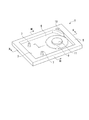
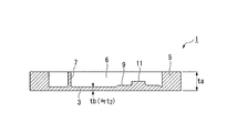
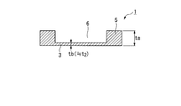
- 1 to 3 show an example of an outline of a basic shape of a typical example of a case body (base) in such a hard disk drive device case.
- the case body 1 has a peripheral portion (four consecutive sides) of a flat bottom portion 3 that is rectangular when viewed in plan, rising in a direction parallel to the thickness direction of the bottom portion 3.
- a side wall portion (outer portion) 5 that is continuous in a square ring shape is formed, and as a whole, one side surface (one side surface in a direction parallel to the thickness direction of the bottom surface portion 3; the upper surface side in the illustrated example) It is made into a thin rectangular box with a bottom open.
- the bottom surface portion 3 and the side wall portion (outer portion) 5 define a storage space 6 for storing functional components such as the hard disk and the motor, head, and actuator described above.
- a large-diameter boss portion 9 corresponding to the hard disk mounting position is formed in a circular raised base shape on one side in the length direction of the bottom surface portion 3, and the motor is connected to the central portion of the large-diameter boss portion 9.
- a small-diameter boss portion 11 for mounting is projectingly formed.
- an air filter holding portion 13 continuous from the side wall portion 5 is formed in the vicinity of the corner portion of the bottom surface portion 3 (corner portion near the large-diameter boss portion 9).
- pins 7 serving as screw portions for attaching the cover are raised at a plurality of locations.
- each part is given a finer shape, or fine projections or depressions other than those described above are formed, but here only the basic parts are shown and the details The shape is omitted.
- the cover in the hard disk drive device case is not particularly illustrated, but is made, for example, in a simple flat rectangular shape.
- the cover is placed on the open side of the case body 1 and is attached to the case body 1 using the pins 7, and a gap between the peripheral portion of the cover and the upper edge surface of the side wall portion 5 of the case body 1 is a gasket or the like.
- the housing space 6 of the case body 1 is sealed by being sealed by the sealing member.
- the case body 1 of the hard disk drive device having such a shape has a thick portion and a thin portion mixed, and the difference in thickness between the thickest portion and the thinnest portion is large. It is normal.
- the thickness (thickness) of the case body 1 means a dimension in a direction orthogonal to the plate surface of the bottom surface portion 3 (that is, a direction parallel to the thickness direction of the bottom surface portion 3).
- the thickest part is the side wall part 5, while the thinnest part is the bottom part 3.
- the thickness tb of the bottom surface part 3 is usually about 30% or less with respect to the thickness ta of the side wall part 5. More specifically, a typical example of dimensions is that the thickness ta of the thickest side wall 5 is about 5 mm, and the thickness tb of the thinnest bottom 3 is about 0.7 mm. In this case, the ratio of the thickness tb to the thickness ta is 14%.
- This type of hard disk drive device case is required to have excellent sealing properties so that external dust and moisture do not enter. In order to maintain good sealing performance, it is necessary that the case is difficult to be deformed and therefore has high rigidity.
- the mounting accuracy of each component constituting the hard disk drive device be high, and for this purpose, it is desired that the dimensional accuracy of each part in the case is high.
- the case material must have excellent formability, excellent cutting properties in final finishing, etc., and high strength so that the detailed shape can be maintained stably.
- the jointability when each component is attached is also good.
- heat dissipation (thermal conductivity) is good from the viewpoint of preventing thermal deformation, and weight is also important from the viewpoint of weight reduction of electronic equipment.
- an aluminum alloy is generally often used as the case body and cover in the hard disk drive device case.
- the case body of this type of aluminum alloy hard disk drive device case is a case in which a die-cast material is cast directly from a molten aluminum alloy, and the die-cast material is subjected to finish processing such as cutting as appropriate.
- the body is usually finished (see, for example, Patent Document 1 and Patent Document 2).
- the hard disk drive device case particularly the case body, has a thick portion and a thin portion mixed as described above, and the difference in thickness between them is large. Therefore, when manufacturing the case body by die casting, when the molten aluminum alloy is press-fitted into the die casting mold, the molten aluminum alloy does not sufficiently turn around the thin-walled portion. In many cases, it is not possible to accurately form a simple shape portion. In that case, there is a problem that the dimensional accuracy and strength of the thin-walled portion and the fine-shaped portion are lowered, and as a result, the sealing performance as a hard disk drive device case is deteriorated and the yield of good products is lowered.
- the material composition when manufacturing the case body by die casting, the material composition must be selected mainly from the viewpoint of molten metal flow during die casting, and the various characteristics required for the case body are therefore required. In particular, it is often the case that the strength and rigidity are not always satisfied.
- the present invention has been made against the background of the above circumstances, and as a case body of a hard disk drive device case, it is difficult to cause defects in a thin portion, and a thin portion and a fine shape portion are accurately formed with high dimensional accuracy.
- a hard disk drive case aluminum alloy case body that can satisfy the various properties required for the hard disk drive case body, such as rigidity, strength, machinability, bondability, and sealability. It is an object of the present invention to provide a manufacturing method and an aluminum alloy case body manufactured thereby.
- the present inventors have conducted various experiments and studies on a method for manufacturing an aluminum alloy case body, and as a result, it is optimal to apply forging. Rather than applying either forging or cold forging alone, it is appropriate to forge to an intermediate material of approximate shape by hot forging, and then finish into a shaped material by cold forging, In that case, after the first stage of hot forging, immediately after the second stage of cold forging, it is found that it is appropriate to rapidly cool by removing heat from the cold forging die.
- the present invention has been made.
- the present invention provides each aspect described in the following (1) to (11).
- a method for manufacturing a bottomed box-shaped aluminum alloy hard disk drive device case body shaped material with one side open For a forging material made of an aluminum alloy, a first stage forging step of die forging to an intermediate material by hot forging using a hot forging die, After the completion of the first stage forging process, taking out the intermediate material from the hot forging die, transferring the intermediate material to the position of the cold forging die, and charging the cold forging die; and A second stage forging step in which the intermediate material is die forged into a shape of a shape for a hard disk drive device case body by cold forging, In the second stage forging step from the transfer step, the intermediate material is brought to the cold forging temperature by removing heat from the cold forging die while the intermediate material is charged into the cold forging die and cold forging.
- the “shape material” means a machine process (part of the surface is cut or polished), a hard disk, a final product for a case body product for use in a hard disk drive case. It means the one after the plastic working before the machining such as drilling for attaching each functional part of the drive device and other surface treatment.
- the hard disk drive case body has a large difference in thickness between the thick and thin parts, and in order to attach each component of the hard disk drive with high precision, it has a fine shape with high dimensional accuracy.
- hot forging alone it is difficult to form thin-walled parts and fine-shaped parts with high precision, and the deformation amount of the material locally increases in those parts.
- the processing heat generation becomes large, and as a result, even if the material temperature is adjusted appropriately, local melting occurs due to the processing heat generation, resulting in seizure to the mold or material embrittlement locally. There is a risk of it.
- the shape of the raw material to be obtained is close to some extent at the stage of hot forging. Since it is only necessary to mold to the shape and dimensions of the intermediate material, and then to the desired raw material shape by cold forging, reduce the burden at the time of hot forging on thin parts and finely shaped parts, The above problem can be avoided. Moreover, after taking out from the hot forging die, it is rapidly cooled by removing heat from the cold forging die when inserted into the cold forging die in the second stage forging step and cold forging.
- thick and thin are the thickness of the cross section in a direction perpendicular to the plate surface of the surface (bottom surface) opposite to the open side in the case body shaped material having a bottomed box shape.
- the dimension is thickness, and it means the size of the thickness dimension of the cross section.
- the solidus temperature of the forging material aluminum alloy is T ° C.
- the hot forging in the first stage forging step is in the range of [T-100] ° C. to [T-50 ° C.].
- performing cold forging in the second stage forging process at a temperature of 80 ° C. or less, and in the cooling process from the transfer process after the completion of the first stage forging process to the second stage forging process.
- a method for producing a shaped material for an aluminum alloy hard disk drive device case body, wherein an average cooling rate from a temperature of [T-100] ° C. to 80 ° C. or less is 50 ° C./sec or more.
- the base material for case body to be manufactured has a thin flat bottom surface portion, and a side wall portion rising from an edge of the bottom surface portion toward one side of the bottom surface plate surface, and
- the recessed space defined by the bottom surface portion and the side wall portion is a storage space for storing the functional components of the hard disk and the hard disk drive device
- In the first stage forging step at least part of the plate-like material is thinned to form an intermediate recess to be the storage space
- the bottom surface of the intermediate recess is further thinned to form the storage space, and the aluminum alloy hard disk drive device case body manufacturing method.
- a forging material for a hard disk drive device case body made of aluminum alloy is subjected to hot forging by applying back pressure to at least a part of the forging material.
- a part for applying back pressure in the hot forging in the first stage forging process a part that becomes a thick part in the intermediate material after hot forging, for example, a part that becomes a side wall part, is selected, and a thin part It is preferable not to apply a back pressure to a part that becomes, for example, a part that becomes a bottom surface portion. That is, the hard disk drive device case body to be manufactured in the present invention has a thick portion and a thin portion, and the thickest portion and the thinnest portion have a large difference in thickness, but becomes a thick portion.
- the aluminum alloy hard disk drive device case body shaped material of any one of (1) to (7) As the aluminum alloy of the forging material, Si: 5 to 12% (mass%, the same applies hereinafter), Fe: 0.1 to 1.0%, Cu: less than 1.0%, Mg: 0.3 to 1.
- Such an Al—Si eutectic alloy is formed by solid solution (solution) of elements such as Mg by rapid cooling after the first stage forging process by hot forging, and natural aging or artificial work after the second stage forging. It is possible to ensure high strength and rigidity by aging, as well as excellent forgeability, machinability and weldability, so it is ideal for the hard disk drive case body material of the present invention. It is.
- These 6000 series alloys, 7000 series alloys, and 2000 series alloys also dissolve elements such as Mg by rapid cooling after the first stage forging process by hot forging, similar to the above-described Al—Si eutectic alloy ( It is possible to ensure high strength and rigidity by natural aging or artificial aging after the second stage forging.
- crystal grains can be refined by rapid cooling after the first stage forging process by hot forging, and relatively high strength and rigidity can be obtained.
- the aluminum alloy hard disk drive device case body shape material manufacturing method of the present invention as a case body shape material used in a hard disk drive device case, a thin portion is less likely to be defective, Even finely shaped parts can be accurately molded with high dimensional accuracy, and the characteristics required for the hard disk drive case body, such as rigidity, strength, machinability, bondability, and sealability, are fully satisfied.
- the obtained aluminum alloy case body shape material can be obtained reliably and easily.
- FIG. 1 is a schematic illustration showing an embodiment of a method for producing a shaped material for an aluminum alloy hard disk drive device case body according to the present invention. It is a schematic diagram for demonstrating the dimensional change of the raw material in each step in one Embodiment of the shaping
- FIG. 7 shows an example of the hot forging die
- FIG. 7 shows an example of the hot forging die
- FIG. 7 shows an example of the hot forging die
- FIG. 7 shows an example of the hot forging die
- FIG. 7 shows an example of the lower mold
- the material of the base material for the hard disk drive device case body is not particularly limited as long as it is an aluminum alloy that can be forged.
- the first stage forging step hot forging
- the solution forging effect can be expected by utilizing the rapid cooling due to heat removal from the cold forging die when the cold forging in the second stage forging process is performed on the finished hot forging material (intermediate material). . Therefore, it is desirable to select an aluminum alloy that can be hardened by age precipitation (age hardening) as an aluminum alloy as a raw material.
- an aluminum alloy containing an element that can contribute to age hardening is used, and the element that contributes to age hardening is solidified by positively utilizing the solution effect by rapid cooling in the transfer step after the first stage forging step. It is desirable to select an aluminum alloy which can be melted and precipitate the element by natural aging (or artificial aging in some cases) to increase the strength, and use it as a material for a hard disk drive case body.
- Aluminum alloys are known as aluminum alloys that can be strengthened by such solution-aging and are suitable for forging.
- Al—Si eutectic alloy in particular, an “AHS” alloy (registered trademark) containing Al—Si—Cu—Mg as a basic component.
- Al—Si eutectic alloy in particular, an “AHS” alloy (registered trademark) containing Al—Si—Cu—Mg as a basic component.
- Al—Si eutectic alloy in particular, an “AHS” alloy (registered trademark) containing Al—Si—Cu—Mg as a basic component.
- 6000 series Al—Mg—Si based alloys 7000 series Al—Zn—Mg based alloys or Al—Zn—Mg—Cu based alloys
- 2000 based Al—Cu based alloys any of them can be used as a case material of the present invention.
- the above-mentioned “AHS” is a registered trademark of Showa Denko KK
- the above-mentioned 6000 series alloy means an alloy whose initial number is “6” as a 4-digit alloy number in Japanese JIS standard, US AA standard or German DIN standard.
- the 7000 series alloy and the 2000 series alloy mean alloys having a prefix of “7” and “2” as 4-digit alloy numbers in the same standard.
- the aluminum alloy used as the material for the case body in the present invention is not limited to an alloy that can be strengthened by solution-aging, and when high strength and high rigidity are not required,
- a 1000 series alloy that is, a pure aluminum series alloy.
- Al—Si eutectic alloy represented by the aforementioned “AHS” alloy is an alloy in which eutectic Si particles are crystallized in a matrix.
- Si 5 to 12% (mass%, the same applies hereinafter)
- Fe 0.1 to 1.0%
- Cu less than 1.0% (including 0%)
- Mg 0.3
- it contains ⁇ 1.5%, with the balance being Al and inevitable impurities.
- such an Al—Si eutectic alloy dissolves elements such as Mg by rapid cooling in the transfer process to the second stage forging process after the first stage forging process by hot forging.
- Si is distributed as eutectic Si in the matrix, improves the rigidity, and coexists with Mg to precipitate Mg 2 Si particles to improve the strength of the aluminum alloy. Further, the eutectic Si particles are dispersed in the matrix, so that the chip breaking property is improved and the free cutting property is improved. If Si is less than 5%, these effects cannot be obtained sufficiently. On the other hand, if Si exceeds 12%, primary crystal Si is crystallized and forgeability is lowered. Therefore, Si is preferably in the range of 5 to 12%. The Si content is more preferably in the range of 9 to 12% even in the range of 5 to 12%, and further preferably in the range of 10 to 11%.
- the particle diameter of the eutectic Si particles is preferably 8 ⁇ m or less. If the particle size of the eutectic Si particles exceeds 8 ⁇ m, the forgeability is lowered.
- the particle diameter of the eutectic Si particles is more preferably in the range of 0.4 to 5.5 ⁇ m, and still more preferably in the range of 0.8 to 5.5 ⁇ m.
- the particle size of the eutectic Si particles is 8 ⁇ m or less, or in the range of 0.4 to 5.5 ⁇ m, or in the range of 0.8 to 5.5 ⁇ m” means that the substantial particle size distribution is For example, 95% or more, preferably 98% or more of the number of eutectic Si particles of all the eutectic Si particles measured by the image processing method of the microscopic observation photograph of about 400 times is included. It means within these ranges.
- Fe precipitates Al—Fe and Al—Fe—Si particles, refines the recrystallized grains during the first stage forging (hot forging), and then the second stage forging (cold forging). ) Forging processability of the process is improved, and it becomes possible to easily process into a complicated and fine shape. If the Fe content is less than 0.1%, this effect is small. On the other hand, if it exceeds 1.0%, Al—Fe and Al—Fe—Si coarse crystals are increased and forgeability is lowered.
- the amount of Fe is preferably in the range of 0.1 to 1.0%.
- the Fe content is preferably 0.1 to 0.5%, more preferably 0.21 to 0.3%.
- Cu If Cu is contained, CuAl 2 particles are precipitated, which contributes to improving the strength of the aluminum alloy. If the Cu content is 1% or more, the forgeability deteriorates, so the Cu content is preferably less than 1%. The Cu content is more preferably 0.9% or less, and even more preferably less than 0.5%. However, Cu may not be contained substantially. That is, Cu may be contained in a small amount as 0% or an inevitable impurity.
- Mg If Mg is contained, it coexists with Si and precipitates Mg 2 Si particles, which contributes to improving the strength of the aluminum alloy. If the Mg content is less than 0.3%, the effect of improving the strength is small, while if the Mg content exceeds 1.5%, the forgeability is lowered. Therefore, the Mg content is preferably in the range of 0.3 to 1.5%. The Mg amount is more preferably in the range of 0.4 to 1.0%.
- each element of Si, Fe, Cu, and Mg in the Al—Si eutectic alloy may basically be Al and inevitable impurities.
- Mn 0.1 To 1% (preferably 0.2 to 0.4%)
- Cr 0.04 to 0.3% (preferably 0.15 to 0.25%)
- Zr 0.04 to 0.3% (preferably 0.1 to 0.2%)
- V 0.01 to 0.1% (preferably 0.05 to 0.1%)
- Al—Mn, Al—Mn—Fe—Si, Al—Cr, Al—Cr—Fe—Si, Al—Zr, and Al—V particles are precipitated. And refining the recrystallized grains during the first stage forging (hot forging), improving the forging processability in the subsequent second stage forging (cold forging) process, and easily with complex and fine shapes It becomes possible to process.
- Ti 0.01 to 0.3% (preferably 0.01 to 0.2%, more preferably 0.002 to 0.1%)
- B 0.0001 to 0.05% (preferably 0.005 to 0.1%)
- Sr 0.001 to 0.2% (preferably 0.005 to 0.1%, more preferably 0.005) Or 0.05%)
- Ti and B are added, the structure of the ingot can be refined, cracking of the ingot during casting can be prevented, and forgeability can be further improved.
- Sr is added, eutectic Si can be refined and forgeability can be improved.
- a 6000 series alloy when used as a forging material, an alloy of 6xxx series as defined in JIS standard, AA standard, DIN standard or ISO standard, for example, JIS 6061 alloy JIS 6063 alloy, JIS 6082 alloy, JIS 6060 alloy, JIS 6N01 alloy and the like.
- JIS 6061 alloy JIS 6063 alloy, JIS 6082 alloy, JIS 6060 alloy, JIS 6N01 alloy and the like for example, Si: 0.3% to 1.0%, Cu: 0.2% to 0.6%, Mg: 0.8% to 1.5%, Cr: 0.14% to It is desirable to use an alloy of 0.3%, Mn: 0.14% to 0.3%, Fe 0.18% to 0.50%, and the balance being Al and inevitable impurities.
- Si coexists with Mg to form Mg 2 Si-based precipitates and contributes to improving the strength of the case body that is the final product. If the Si content is less than 0.3%, the effect of precipitation strengthening is reduced. On the other hand, if the Si content exceeds 1.0%, grain boundary precipitation of Si increases, and grain boundary embrittlement tends to occur. Since the toughness of the product is lowered, the Si content is preferably in the range of 0.3% to 1.0%.
- Cu increases the apparent supersaturation amount of Mg 2 Si-based precipitates and promotes age hardening of the final product by increasing the Mg 2 Si precipitation amount. However, if the Cu amount is less than 0.2%, sufficient On the other hand, if the amount of Cu exceeds 0.6%, the corrosion resistance is lowered. Therefore, the amount of Cu is preferably in the range of 0.2% to 0.6%.
- Mg coexists with Si to form Mg2Si-based precipitates and contributes to improving the strength of the case body that is the final product. If the Mg content is less than 0.8%, the effect of precipitation strengthening is small. On the other hand, if the Mg content exceeds 1.5%, the toughness of the final product is lowered, so the Mg content is 0.8% to 1.5%. Within the range of is preferable.
- Cr crystallizes out as an AlCrSi phase, and Cr that does not crystallize precipitates and contributes to suppression of recrystallization. However, if the Cr content is less than 0.14%, the above-described effects are reduced, while the Cr content is 0.3%. If it exceeds 50%, a giant intermetallic compound may be formed and embrittlement may occur, so the Cr content is preferably in the range of 0.14% to 0.3%.
- Mn crystallizes as an AlMnSi phase, and Mn that does not crystallize precipitates and contributes to suppression of recrystallization.
- the amount of Mn is less than 0.14%, the above-described effects are reduced, while the amount of Mn is 0.3. If it exceeds 50%, a huge intermetallic compound may be formed and embrittlement may occur. Therefore, the Mn content is preferably in the range of 0.14% to 0.3%.
- Fe crystallizes as an AlFeSi phase, prevents coarsening of grains, reduces quenching sensitivity, improves strength and toughness, and contributes to improvement of corrosion resistance, but if the Fe amount is less than 0.18%, The effect is reduced. On the other hand, if the amount of Fe exceeds 0.50%, the above effect is lost. Therefore, the amount of Fe is preferably in the range of 0.18% to 0.50%.
- Ti 0.002 is used in order to improve forgeability through refinement of the ingot structure or refinement of the Al—Si eutectic particles as in the case of the Al—Si eutectic alloy described above. 01 to 0.3% (preferably 0.01 to 0.2%, more preferably 0.002 to 0.1%), B: 0.0001 to 0.05% (preferably 0.005 to 0.00). 1%), Sr: 0.001 to 0.2% (preferably 0.005 to 0.1%, more preferably 0.005 to 0.05%). May be.
- ⁇ 7000 series alloy> an alloy of 7xxx series as defined in JIS standard, AA standard, DIN standard, ISO standard, etc., for example, JIS 7001 alloy, JIS It can be appropriately selected from 7050 alloy, JIS 7075 alloy, JIS 7475 alloy, JIS 7N01 alloy and the like.
- JIS 7001 alloy JIS 7001 alloy
- JIS It can be appropriately selected from 7050 alloy, JIS 7075 alloy, JIS 7475 alloy, JIS 7N01 alloy and the like.
- Zn 3% to 10%
- Mg 1.0% to 3.0%
- Si 0.5% or less
- Fe 1.5% or less
- the balance being Al and inevitable impurities It is desirable to use an alloy made of or an alloy containing 0.2% to 2.6% of Cu in addition to these elements.
- ⁇ 2000 series alloy> In the production method of the present invention, when a 2000 series alloy is used as a forging material, an alloy of 2xxx series as defined in JIS standard, AA standard, DIN standard or ISO standard, for example, JIS 2014 alloy, JIS It can be appropriately selected from 2017 alloy, JIS 2024 alloy, JIS 2218 alloy, JIS 2618 alloy and the like.
- JIS 2014 alloy JIS 2014 alloy
- JIS It can be appropriately selected from 2017 alloy, JIS 2024 alloy, JIS 2218 alloy, JIS 2618 alloy and the like.
- Cu 1.5% to 5.0%
- Mg 0.2% to 1.8%
- Si 0.2% to 1.2%
- Fe 1.5% or less
- an alloy of 1xxx series in accordance with JIS standard, AA standard, DIN standard, or ISO standard such as JIS 1050 alloy, JIS 1100 alloy, JIS 1060. It can be appropriately selected from an alloy, a JIS 1200 alloy, a JIS 1N00 alloy and the like.
- an alloy in which Fe is 1% or less, Si is 0.5% or less, Mn is 0.05% or less, and the balance is Al and other inevitable impurities is used. Is preferred.
- the first stage forging by hot die forging is applied to the plate-shaped forging material made of the aluminum alloy as described above. Forging into an intermediate material having a shape and size that is close to the shape and dimensions of the case body shape material, then removing the intermediate material from the hot forging die and immediately removing the intermediate material from the cold forging die. The intermediate material is inserted into a cold forging die, the second stage forging is applied to the intermediate material by cold die forging, and the hard disk drive device case body is finished.
- the intermediate material is charged into the cold die forging die and the second stage forging in the cold is performed, as described above, from the cold forging die.
- the intermediate material is rapidly cooled by heat removal.
- the case body shape material to be manufactured is similar to the case body described with reference to FIGS. That is, it has a shape and size that can be finished into a case body by finishing such as final cutting. Therefore, in the following description, the case body shown in FIGS. 1 to 3 is regarded as a case body material, and the names and symbols of the respective parts of the case body material are also shown in FIG. Basically, the case body shape material is formed of, for example, a rectangular long plate-like thin and flat bottom surface portion 3 and its bottom surface portion 3.
- a recessed space that has a side wall (outer part) 5 that rises from one edge to the side of the plate surface of the bottom surface and continues in an annular shape and is partitioned by the bottom surface and the side wall 6 corresponds to a storage space for storing the functional components of the hard disk and the hard disk drive device.
- the target dimensions of the respective parts of the case body shape material to be manufactured are the thinnest bottom surface portion with respect to the thickness ta of the thickest side wall portion 5, for example, as described for the case body with reference to FIGS.
- the ratio of the thickness tb of 3 is desirably 30% or less. That is, the following equation t 2 ⁇ 0.3 ⁇ ta It is preferable to satisfy.
- the thickness ta of the thickest side wall 5 is about 5 mm
- the thickness tb of the thinnest bottom 3 is about 0.7 mm.
- the ratio of the thickness tb to the thickness ta is 14%. It is.
- FIGS. 1-10 An example of a typical embodiment of a method for manufacturing a shaped material for a hard disk drive device case body of the present invention will be described with reference to FIGS.
- the forging material 20 in the present embodiment is a flat plate having a predetermined thickness that is rectangular when viewed in plan, and is made of an aluminum alloy having the above-described component composition. Yes.
- the plate surface size of the flat forging material 20 is a size that can be inserted into the cavity of the lower die in the first stage forging (hot forging) described below, in other words, a case element to be finally obtained. It is determined to have a dimension approximately equal to the planar dimension of the outer shape of the profile (see FIGS. 1 to 3).
- the thickness t 0 of the flat plate-like material 20 is the overall thickness of the case body shaped material 30 to be finally obtained (corresponding to the thickest portion of the case body shaped material, ie, the thickness ta of the side wall portion 5).
- the first stage forging is performed so as to increase the thickness of the side wall portion 5.
- the thickness t 0 of the material 20 is set to be smaller than the thickness ta of the side wall portion 5 of the case body 1. Specifically, the thickness t 0 of the material 20 is about 2 to 10 mm, typically about 3 mm.
- Such a flat forging material 20 is preheated to a required hot forging temperature by a heating furnace (not shown) and the like, and is charged into the cavity 24Ba of the lower die 24B for hot forging in the forging machine 22, The forging upper die 24A is lowered to perform the first stage forging.
- the forging machine 22 is hot forging so that the first stage forging (hot forging) and the second stage forging (cold forging) can be performed in the same forging machine.
- An upper die 24A for hot forging and a lower die 24B for hot forging constituting the die, and an upper die 26A for cold forging and a lower die 26B for cold forging constituting the cold forging die are arranged in parallel.
- the hot forged material can be taken out from the hot forging lower die 24B, transferred to the position of the cold forging lower die 26B by a transfer mechanism (not shown), and immediately inserted into the cold forging lower die 26B. It is said.
- a forging machine having such a transfer function is referred to as a forging machine with transfer.
- an upper die 24A for hot forging and an upper die 26A for cold forging are attached in parallel to the lower side of the upper plate 22A, and the lower die for hot forging is located above the lower plate 22B.
- 24B and the lower die 26B for cold forging are attached in parallel, and the upper plate 22A is raised and lowered by a pressure raising and lowering mechanism (not shown), whereby the upper die 24A for hot forging and the upper die 26A for cold forging are raised and lowered. It is configured to be able to.
- the plate-like material 20 is basically hot forged in order to form the intermediate recess 6A to be the housing space 6 of the case body shaped material 30. This is a process of reducing the thickness.
- a hard disk, a functional part, or a part for attaching or supporting a cover such as the large-diameter boss part 9, the small-diameter boss part 11, the air filter shown in FIGS.
- the portion corresponding to the holding portion 13 or the pin 7 is also formed in the first stage forging (hot forging) step.
- the material 20 is charged into the cavity 24Ba of the lower die 24B for hot forging, and the upper die 24A for hot forging is lowered, and the inside of the cavity 24Ba
- the material 20 is hot forged and formed into an intermediate material 28 having a predetermined intermediate shape and intermediate dimensions.
- the intermediate member 28 basically has a plate-like bottom surface portion 3A to be the bottom surface portion 3 of the case body shape member 30, and one edge of the bottom surface portion 3A with respect to the plate surface of the bottom surface portion 3A. It is set as the shape which has 5 A of side wall parts (outer part) which stand
- a recessed space 6 ⁇ / b> A defined by the bottom surface portion 3 ⁇ / b> B and the side wall portion 5 ⁇ / b> A is a space that becomes the storage space 6.
- the intermediate member 28 usually has a portion for attaching or supporting a hard disk, a functional component, or a cover as necessary.
- the shape of the intermediate material 28 and the dimensions of each part are preferably close to the shape and dimensions of the case body shape material to be obtained, as will be described later.
- the thickness of the thinnest portion (usually the bottom surface portion 3A) of the intermediate material 28 after the completion of the first stage forging step (hot forging) is t 1
- the thickness of the second-stage forging (cold forging) the thinnest portion in the formed and fabricated material 30 after the end (usually the bottom portion 3) and t 2 the thickness t 0 of the material 20
- the upsetting in the first stage forging process is preferably 60% or more.
- the thickness of the material is t 0
- the thickness of the bottom surface portion 3A of the intermediate recess 6A in the intermediate material 28 after completion of the first stage forging step is t 1
- the thickness of the intermediate material 28 after the first stage forging process is, for example, the thickness t 1 of the thinnest portion (usually the bottom surface portion 3A) is about 0.5 to 4.0 mm (representative)
- the thickness ta ′ of the thickest portion is about 4 to 25 mm (typically 5 mm).
- the thickest portion (usually the side wall portion 5A), as will be described again later, by applying a back pressure during hot forging, it is desirable to increase meat from the material thickness t 0, the thus
- the thickness of the thickest part (side wall portion 5A) after the first stage forging process (hot forging) is increased to the second stage forging process (up for cold forging).
- the thickness ta ′ be close to the thickness ta of the thickest portion (side wall portion 5) of the case body shape member 30.
- the thickness ta ′ of the thickest portion (side wall portion 5A) in the shaped material 30 after the first stage forging process (hot forging) is increased by the second stage forging process (cold forging). It is desirable that the thickness be within a range of 100 to 110% of the thickness ta of the thickest wall portion (side wall portion 5) of the raw material 30.
- the material temperature during forging in the first stage forging process is not more than [solidus temperature of material alloy-50 ° C] and not less than [solidus temperature of material alloy-100 ° C]. It is desirable to be inside.
- the material temperature at the forging in the first stage forging process is a low temperature less than [solidus temperature of material alloy ⁇ 100 ° C.]
- the deformation resistance of the material is large
- the finely shaped portion there is a risk that defects such as a lack of thickness may occur in the intermediate material after hot forging.
- the first stage forging is used. If the material temperature at the time is lower than [solidus temperature of material alloy-100 ° C], elements that contribute to age hardening, such as Mg, cannot be sufficiently dissolved, and as a result, It becomes difficult to improve the strength by age hardening.
- the material temperature at the forging in the first stage forging process exceeds the [solidus temperature of the material alloy-50 ° C], it is locally generated by heat generated by plastic processing during hot forging. Melting may occur and seizure may occur on the mold, or strength may be reduced.
- the material temperature at the forging in the first stage forging process exceeds the [solidus temperature of the material alloy-50 ° C]
- it is necessary to greatly reduce the thickness of the thinnest part to about 1 mm in the first stage forging even if two-stage forging is applied In addition, a portion having a fine shape must be formed for attaching each component of the hard disk drive. In such large thinned parts and finely shaped parts, the amount of deformation during forging increases and processing heat generation also increases, so if the original material temperature is high, local melting tends to occur at those locations. .
- the forging material is heated to a temperature within the above range immediately before the first stage forging step (hot forging), and then the material is heated. It is desirable to maintain the hot forging temperature within the above range by charging the cavity of the forging die and preheating or maintaining the hot forging die at a certain temperature.
- the solidus temperature of the aluminum alloy varies depending on the component composition, but the alloy used as the Al—Si eutectic alloy in Example 1 described later, that is, Si: 10%, Fe: 0.25% , Cu: 1.0%, Mg: 0.5%, and in the Al—Si—Cu—Mg based alloy consisting of Al and inevitable impurities, the solidus temperature is 540 ° C.
- the material temperature at the time of the forging may be in the range of 490 to 440 ° C.
- the solidus temperature is about 580 ° C. Therefore, the material temperature during hot forging may be in the range of 530 to 480 ° C. .
- an alloy used as a 7000 series alloy in Example 4 that is, Al—Zn—Mg—containing 6.2% Zn, 2.2% Mg, 2.3% Cu, and the balance being Al and inevitable impurities. In the case of a system alloy, the solidus temperature is about 490 ° C.
- the material temperature during hot forging may be in the range of 390 to 440 ° C.
- an alloy used as a 2000 series alloy in Example 5 that is, Al containing Cu 4.0%, Si 0.6%, Mg 0.6%, Mn 0.7%, the balance being Al and inevitable impurities.
- the solidus temperature is about 510 ° C., so the material temperature during hot forging may be in the range of 410 to 460 ° C.
- the pure aluminum (1000 series) alloy used in Example 3 the solidus temperature is about 640 ° C. Therefore, the material temperature at the time of hot forging may be in the range of 540 to 590 ° C. .
- the intermediate material 28 is taken out from the cavity 24Ba of the lower die 24B for hot forging and immediately inserted into the cavity 26Ba of the lower die 26B for cold forging. Enter. Subsequently, as the first stage forging step, the cold forging upper die 26A is lowered to cold forge the intermediate material 28 to obtain a case body shaped material 30.
- the intermediate material 28 taken out from the cavity 24Ba of the lower die 24B for hot forging is still hot immediately after taking out, but is inserted into the cavity 26Ba of the lower die 26B for cold forging and cooled.
- these cold forging dies (cold forging lowers) are in contact with the cold forging lower die 26B and then in contact with the cold forging upper die 26A while cold forging proceeds.
- the mold 26B and the upper mold 26A for cold forging are deprived of heat (heated off) and rapidly cooled.
- the transfer of heat from the intermediate material 28 to the cold forging die is performed by inserting the intermediate material 28 into the cold forging die, and the intermediate material 28 is cooled by the cold forging lower die 26B and the cold forging die. Occurs during the period from when the intermediate material 28 is in contact with the surface of the upper forging die 26A until the forged molded product is discharged from the cold forging die, mainly during the plastic deformation of the intermediate material 28 by cold forging. In the meantime, the heat of the intermediate material 28 moves from the surface of the cold forging die to the inside of the die, and the intermediate material 28 is rapidly cooled to a temperature of 80 ° C. or lower.
- age-hardening Al alloys such as Al-Si eutectic alloys and 6000 series alloys represented by the “AHS” alloy as described above are used, after the above hot forging By rapidly cooling, it is possible to achieve solid solution of component elements contributing to age hardening, that is, to form a solution. That is, a so-called die quench effect can be obtained. Therefore, in that case, it is possible to increase the strength by natural aging after the second stage forging.
- heat treatment may be performed as an artificial aging treatment as described later.
- the cooling rate when the intermediate material is rapidly cooled by heat removal from the cold forging die after the hot forging described above from [solidus temperature of raw material alloy ⁇ 100 ° C.] to 80 ° C. or less. It is desirable that the average cooling rate during the period is 50 ° C./sec or more.
- an age-hardening type Al alloy such as an Al—Si eutectic alloy or 6000 alloy as described above is used, rapid cooling after hot forging is performed. Thus, it is ensured that the component elements contributing to age hardening are dissolved, that is, the solution is achieved. If the average cooling rate between the above [solidus temperature of the raw material alloy ⁇ 100 ° C.] and below 80 ° C.
- the average cooling rate during the period from [solidus temperature of raw material alloy ⁇ 100 ° C.] to 80 ° C. or lower is preferably 90 ° C./sec or higher, even within the above range.
- a cooling means is provided in the cold forging die as described later, and an intermediate material is inserted. It is preferable not to raise the temperature of the cold forging die to a high temperature exceeding 80 ° C.
- the upsetting rate of the second stage forging should be 20% or less.
- the thickness of the intermediate material 28 after the second stage forging step (cold forging) is, for example, the thickness t 2 of the thinnest portion (usually the bottom surface portion 3) is about 0.5 to 3 mm (typical example)
- the thickness ta of the thickest part (usually the side wall part 5) is about 4 to 25 mm (typically 5 mm).
- machining to finish the case body product for use in the hard disk drive device case (cutting part of the surface) Processing and polishing), machining such as drilling for mounting each component of the hard disk drive device, and other finishing such as surface treatment are usually performed. Further, depending on the material alloy, finishing may be performed after artificial aging treatment or natural aging by leaving at room temperature.
- a molten aluminum alloy adjusted to a predetermined component composition is a so-called continuous casting method such as a hot casting continuous casting method, a general continuous casting method such as continuous casting rolling (thin plate continuous casting), or a semi-continuous casting method.
- the slab is made by the method.
- continuous casting either horizontal continuous casting or vertical continuous casting may be used, or a gas pressure continuous casting method may be applied.
- the shape of the slab obtained by continuous casting is not particularly limited, and it may be a round bar-shaped billet, a square bar-shaped billet, or a plate shape.
- the continuous cast slab thus obtained is usually subjected to a homogenization treatment as necessary and further subjected to chamfering.
- the homogenization temperature (atmosphere temperature) is preferably 500 ° C. ⁇ 30 ° C. If the homogenization temperature is within this range, the effect of homogenizing segregation during casting can be obtained, and the transition metal element that becomes a recrystallization nucleus does not become coarse, which is preferable from the viewpoint of preventing coarse recrystallization. If the homogenization temperature is less than the above range, it is difficult to obtain the effect of homogenizing segregation during casting.On the other hand, if it exceeds this range, precipitation of transition metal elements becomes coarse, and the effect of preventing coarse recrystallization is obtained. Get smaller.
- the holding time of the homogenization treatment at a temperature within the above range is preferably 5 hours to 20 hours.
- the homogenization process with respect to a slab can be abbreviate
- material processing is performed in order to process the material into a shape suitable for the first stage forging process (hot forging) (for example, a flat plate with a rectangular plate surface shape) and dimensions.
- a shape suitable for the first stage forging process for example, a flat plate with a rectangular plate surface shape
- shear cutting, extrusion processing, upsetting processing, or the like may be applied according to the shape of the slab.
- two or more types of processing may be combined.
- the continuous cast slab is a round bar-shaped billet
- the round bar-shaped billet is shear-cut into a predetermined short length and processed into a flat plate of the desired size by upsetting or extruding. It ’s fine.
- the continuous cast slab is a thin plate, it can be used as a forging material only by shear cutting.
- upsetting or extruding when upsetting or extruding is applied as a processing means for processing a slab into a flat forging material of a predetermined dimension, the upsetting or extruding is hot or warm. In that case, upsetting or extrusion may be performed after preheating before forging described below, and hot forging as the first stage forging process may be performed immediately thereafter.
- a round bar-shaped slab is used, cut into a short round bar having a predetermined length, and subjected to upsetting for the short round bar.
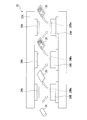
- An example of the forging machine 22 in the case of performing cold forging as the hot forging, transfer process and second-stage forging process is shown in FIG. In FIG. 6, the forging machine with transfer 22 is capable of upsetting, and first stage forging (hot forging) and second stage forging (cold forging) in the same forging machine.
- the upper die 26A for cold forging and the lower die 26B for cold forging constituting the same are arranged in parallel. That is, an upper die 29A for upsetting, an upper die 24A for hot forging, and an upper die 26A for cold forging 26A are mounted in parallel on the lower side of the upper plate 22A of the forging machine 22 and on the upper side of the lower plate 22B.
- the lower die 29B for upsetting, the lower die 24B for hot forging, and the lower die 26B for cold forging are attached in parallel, and the upper plate 22A is moved up and down by a pressure raising / lowering mechanism (not shown), and the upper die for upsetting 29A, the upper die 24A for hot forging and the upper die 26A for cold forging can be moved up and down.
- the above-mentioned short round bar 31 preheated to a predetermined temperature was inserted into the cavity 29Ba of the lower die 29B for upsetting, and the short round bar 31 was flattened and obtained.
- the flat forging material 20 is charged into the lower die 24B for hot forging in the same manner as described above, and the first stage forging process (hot forging) is performed. , Taken out from the lower die 24B for hot forging, transferred to the position of the lower die 26B for cold forging, and inserted into the lower die 26B for cold forging, and the first stage forging step (hot forging) was carried out can do.
- the forging material is subjected to preheating for heating to the material temperature during forging in the first stage forging process (hot forging).
- the material temperature during forging in the first stage forging process (hot forging) is not less than [solidus temperature of material alloy ⁇ 100 ° C.] and [solidus temperature of material alloy ⁇ 50]. [° C.] It is preferable to set the temperature within the following range. Therefore, the preheating temperature before forging may be set within the range or slightly higher than that range.
- the preheating time may be set so that the inside of the material is uniformly heated to a temperature within the above range, and usually about 10 to 30 minutes is sufficient.
- the time from immediately after the pre-heating to the charging is short so that the material temperature does not decrease during that time. For example, it is preferable to control within 20 seconds.
- the case body shape material which is the subject of the present invention has a thick portion and a thin portion and a fine shape portion at the same time. Therefore, a material for the thin portion and the fine shape portion at the time of hot forging.
- the preset temperature for the preheating is increased or the temperature distribution in the material is made uniform in anticipation of the temperature drop of the material. Therefore, it is preferable to perform control such as appropriately setting the holding time.
- the material temperature during forging in this first stage forging process is, as already stated, [solidus temperature of material alloy-100 ° C] or more and [solidus temperature of material alloy- 50 ° C.] The following range is desirable.
- the first stage forging step it is preferable to perform hot forging with a partial back pressure applied. That is, a portion that becomes a thick portion (for example, a portion corresponding to the side wall portion 5 and the pin 7 in FIGS. 1 to 3) in the case body shape material is thin while applying back pressure. It is preferable to apply a so-called partial back pressure applying forging method in which a portion (for example, the bottom surface portion 3 in FIGS. 1 to 3) is forged without applying a back pressure. An example of a hot forging die for forging a case body material by such a partial back pressure applying forging method is shown in FIGS.
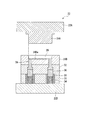
- FIG. 7 and 8 schematically show a longitudinal section of the hot forging die at a position corresponding to the longitudinal section (see FIG. 3) along the line II-II in FIG. 1 in the case body.
- the forging material 20 for the case body is formed by forging with the top and bottom of FIGS. 1 to 3 inverted, that is, the open side of the intermediate material for the case body is facing downward. In this state, it is shown as being forged.
- an upper die 24A for hot forging is attached downward on the lower side of the upper plate 22A of the forging machine 22.
- a lower die 24B for hot forging is attached on the lower plate 22B of the forging machine 22 from the lower side via a holding plate 31 and a pressure receiving plate 32.
- the lower die 24B for hot forging is formed with a cavity 24Ba that opens upward.
- the bottom surface of the cavity 24Ba corresponds to the inner surface of the bottom surface portion of the case body.
- the upper end surface of the back pressure application member 38 mentioned later is exposed to the peripheral part of the bottom face of the cavity 24Ba.
- the holding board 31 holds, for example, a hollow cylindrical pneumatic cylinder 33 as a back pressure cushion that holds back pressure air pressure introduced from the outside.
- a shock-absorbing spring member 34 is accommodated in the lower portion of the inside of the pneumatic cylinder 33, and an intermediate lifting member 36 that can slide up and down is provided above the spring member 34. It is arranged to reach the inside.
- a back pressure application member 38 is disposed on the intermediate lifting member 36.
- the back pressure application member 38 is a member that can be moved up and down with respect to the lower die 24B for hot forging, and is movable for forming the peripheral portion of the forging material 20 (the portion corresponding to the side wall portion of the case body). It can also be called a mold.
- the back pressure applying member 38 is substantially flush with the bottom surface of the cavity 24Ba when the mold is opened (when the upper die 24A for hot forging is at the top dead center: see FIG. 7). It is located to become.
- the plate-like forging material 20 is formed in the cavity 24Ba of the lower die 24B for hot forging with the mold open.
- the upper plate 22A is lowered and the upper die 22A for hot forging is lowered, and a forging load is applied to the material 20 in the cavity 24Ba by the lower surface of the upper die 24A for hot forging.
- the portion of the cavity 24Ba in contact with the bottom surface is directly reduced in thickness by the forging load, and a thin portion (bottom surface portion) is formed.
- an electric heater is provided in the lower die 24B of the hot forging die or the lower die 24B and the upper die 24A so that an appropriate material temperature is maintained at the time of hot forging. It is desirable to preheat or hold these molds at about 200 to 300 ° C. by providing a heating means such as the above.
- the time from when the hot forged intermediate material is taken out of the hot forging die until it is inserted into the cold forging die and cold forging starts (specifically, the intermediate material is cooled). It is desirable to shorten as much as possible the time until the upper die comes into contact with the lower die for intermediate forging and further the upper die comes into contact with the intermediate material. Specifically, it is desirable to set the time from taking out from the hot forging die to inserting into the cold forging die to start cold forging within 10 seconds.
- the lower die 26B for cold forging is constituted by upper and lower die members 26B 1 and 26B 2 .
- a cooling pipe 40 is disposed as a cooling means so as to surround the cavity 26Ba.
- a cooling medium such as cooling water having a water temperature of, for example, about 50 ° C. or lower, preferably 40 ° C. or lower is passed through the cooling pipe 40 to keep the inner surface of the lower die 26B for cold forging, particularly the cavity 26Ba, at a low temperature. be able to.
- ⁇ Aging treatment> When an alloy that can be age hardened, such as an Al—Si eutectic alloy or 6000 alloy, is used as the aluminum alloy material, the shape material after cold forging in the second stage forging process is used as it is. If left at room temperature for about 24 hours or more, high strength can be achieved by natural aging (room temperature aging). However, if higher strength is desired, artificial aging treatment may be performed. The optimum conditions for the artificial aging treatment vary depending on the component composition of the alloy, but it is usually sufficient to heat at about 170 to 220 ° C. for about 1 to 8 hours.
- the surface of the case body shaped material obtained as described above is subjected to cutting or polishing of a portion of the surface as a finishing process.
- machining or machining such as drilling for mounting each component of the hard disk drive, and other finishing such as surface treatment are performed.
- the outer surface portion where the machining accuracy is not required is left as the forged skin after the cold forging.
- it is an attachment part or a joint part of each component of the hard disk drive device and its peripheral part.
- the first embodiment uses an Al—Si eutectic alloy as a forging material alloy, and is a case body for a hard disk drive device case body having a bottomed thin box shape as schematically shown in FIGS. It is the example which manufactured the raw material by forging a raw material with a forging machine as shown in FIG.
- the Al—Si eutectic alloy contains Si: 10%, Fe: 0.25%, Cu: 1.0%, Mg: 0.5%, the balance being Al— consisting of Al and inevitable impurities.
- a Si—Cu—Mg alloy was used.
- the target dimensions of the case body shape material to be finally obtained are a square shape of 70 mm ⁇ 100 mm in plan view, the thickness ta of the thickest part (side wall part 5) is 10 mm, and the thinnest part.
- the thickness tb of (bottom surface portion 3) was 2 mm.
- a molten Al—Si eutectic alloy having the above component composition was melted in accordance with a conventional method, and a round bar-shaped slab having an outer diameter of 28 mm was obtained by a gas pressure hot top continuous casting method.
- the slab was homogenized at 490 ° C. for 10 hours, then the surface was chamfered, cut to a length of 95 mm, preheated to 480 ° C. in a heating furnace, and shown in FIG.
- a plate-shaped material was upset by the upsetting die of the forging machine 22 with transfer.
- the dimensions of the obtained flat plate-like material are 68 mm ⁇ 98 mm in plan view, and the thickness t 0 is 5.5 mm.
- the plate-shaped material after upsetting was immediately inserted into a hot forging die cavity schematically shown in FIGS. 7 and 8, and hot forging (first stage forging) was performed to obtain an intermediate material.
- the raw material temperature at the time of charging into the cavity of the hot forging die was about 460 ° C.
- the mold was preheated to 380 ° C. in advance.
- the portion corresponding to the side wall portion of the case body and the portion corresponding to the pin are applied with a back pressure of 6 kgf / mm 2 , the overall forging load is 250 t, and the forging speed (upper die lowering speed) is 90 mm / sec. Forged.
- the dimension of the obtained intermediate material is a square shape of 70 ⁇ 100 mm when viewed in plan, and the thickness is 9.8 mm at the thickness ta ′ of the thickest part (side wall part 5), and the thinnest part (bottom part 3). the thickness t 1 of) is 2.5 mm.
- the intermediate material taken out from the hot forging die was immediately charged into the cavity of the cold forging die, and second stage forging (cold forging) was performed.
- the cold forging die was cooled and held at 50 ° C. or lower by a cooling means as shown in FIG.
- the time from taking out the intermediate material from the hot forging die, inserting it into the cavity of the cold forging die, and further cold forging is about 2 seconds.
- the average cooling rate while the intermediate material was cooled to 80 ° C. or less in contact with the cold forging die was 180 ° C./sec.
- forging was performed with a forging load of 50 t and a forging speed (upper die lowering speed) of 90 mm / sec.
- the dimensions of the obtained shaped material are 70 mm ⁇ 100 mm in plan view, and the thickness is 10 mm for the thickest part (side wall part 5) and t 2 for the thinnest part (bottom part 3). It was 2 mm.
- the obtained shaped material was left to stand at room temperature for 24 hours and naturally aged.
- the strength of the side wall (thickest wall) of the case body shape material immediately after taking out from the cold forging die is 260 MPa
- the hardness is Hv82
- the strength of the bottom surface is 260 MPa, hard. Therefore, it is apparent that age hardening was achieved by natural aging by leaving for 24 hours.
- the case body shape material taken out of the cold forging die was subjected to an artificial aging treatment at 200 ° C. for 360 minutes, and the side wall portion of the case body shape material (thickest wall portion) ) was 305 MPa, the hardness was Hv99, the strength of the bottom surface portion was 310 MPa, and the hardness was Hv100.
- Example 1 the intermediate material is taken out from the hot forging die, inserted into the cavity of the cold forging die, and the time for further cold forging is changed to about 60 seconds.
- the average cooling rate while the intermediate material is cooled to 80 ° C. or less in contact with the cold forging die from the intermediate material temperature (about 440 ° C.) when taken out from the hot forging die is about 6 ° C./sec.
- the strength of the side wall portion (thickest wall portion) of the case body shape material immediately after taking out from the cold forging die is 260 MPa
- the hardness is Hv82
- the strength of the bottom surface portion is 260 MPa
- the hardness is Hv82
- the strength of the side wall portion (the thickest portion) of the case body shape material after being taken out from the cold forging die and left at room temperature for 24 hours is 266 MPa
- the hardness is Hv83.
- the strength of the bottom surface portion was 268 MPa
- the hardness was Hv84. Therefore, in this case, it has been found that age hardening by natural aging by leaving for 24 hours is not sufficiently achieved.
- the case body shape material taken out of the cold forging die was subjected to an artificial aging treatment at 200 ° C. for 360 minutes, and the side wall portion of the case body shape material (thickest wall portion) ) was 284 MPa, the hardness was Hv91, the strength of the bottom surface portion was 286 MPa, and the hardness was Hv91. Therefore, it can be seen that even when artificial aging is applied, the improvement in strength is small.
- Example 2 In Example 2, a 6000 series alloy is used as the forging material alloy, and a shape material for a hard disk drive device case body having a bottomed thin box shape as schematically shown in FIGS. 4 is an example in which a material is forged by a forging machine with transfer as shown in FIG.
- the target dimensions of the case body shape material to be finally obtained are a square shape of 70 mm ⁇ 100 mm in plan view, the thickness ta of the thickest part (side wall part 5) is 10 mm, and the thinnest part.
- the thickness tb of (bottom surface portion 3) is 2 mm.
- a molten 6000 series alloy having the above component composition was melted in accordance with a conventional method, and a plate-shaped slab having a thickness of 10 mm was obtained by a continuous casting and rolling method (thin plate continuous casting method).
- the plate-shaped slab was homogenized at 540 ° C. for 10 hours, then the surface was chamfered, and then a square plate shape with a plane dimension of 68 mm ⁇ 98 mm by shear cutting (thickness: 5.5 mm) To obtain a flat forging material.
- the flat forging material is preheated to 530 ° C. in a heating furnace, and immediately inserted into a cavity of a hot forging die schematically shown in FIGS.
- hot forging first stage forging
- I went and got an intermediate material.
- the raw material temperature at the time of charging into the cavity of the hot forging die was about 520 ° C.
- the mold was preheated to 480 ° C. in advance.
- the portion corresponding to the side wall portion of the case body and the portion corresponding to the pin are applied with a back pressure of 5 kgf / mm 2
- the overall forging load is 220 t
- the forging speed (upper die lowering speed) is 90 mm / sec. Forged.
- the dimensions of the obtained intermediate material are 70 mm ⁇ 100 mm in plan view, and the thickness is the thickness ta ′ of the thickest part (side wall part 5) is 9.8 mm, and the thickness t of the thinnest part (bottom part 3). 1 is 2.5 mm.
- the intermediate material taken out from the hot forging die was immediately charged into the cavity of the cold forging die, and second stage forging (cold forging) was performed.
- the cold forging die was cooled and held at 50 ° C. or lower by a cooling means as shown in FIG.
- the time from taking out the intermediate material from the hot forging die, inserting it into the cavity of the cold forging die, and further cold forging is about 2 seconds.
- the average cooling rate while the intermediate material was in contact with the cold forging die and cooled to 80 ° C. or less was 215 ° C./sec.
- forging was performed with a forging load of 40 t and a forging speed (upper die lowering speed) of 90 mm / sec.
- the dimensions of the obtained shaped material are 70 mm ⁇ 100 mm in plan view, and the thickness is 10 mm for the thickest part (side wall part 5) and t 2 for the thinnest part (bottom part 3). It was 2 mm.
- the obtained shaped material was allowed to stand at room temperature for 24 hours to cause natural aging.
- the strength of the side wall portion (the thickest portion) of the case body shape material immediately after taking out from the cold forging die is 170 MPa
- the hardness is Hv58
- the strength of the bottom surface portion is 170 MPa
- the hardness is Hv58. Therefore, it is clear that age hardening was achieved by the natural aging by leaving for 24 hours.
- the case body shape material taken out of the cold forging die was subjected to an artificial aging treatment at 180 ° C. for 360 minutes, and the side wall portion of the case body shape material (thickest wall portion) ) Has a strength of 240 MPa, a hardness of Hv74, and a bottom surface strength of 250 MPa and a hardness of Hv76.
- Example 3 uses a pure aluminum alloy (1000 alloy) as an alloy for forging, and is used for a hard disk drive device case body having a bottomed thin box shape as schematically shown in FIGS. It is the example which manufactured the raw material forging the raw material with the forging machine with a transfer as shown in FIG.
- 1000 alloy pure aluminum alloy
- Example 3 is different from Example 2 in that the homogenization process after continuous casting is omitted and the chamfering process after the homogenization process is omitted.
- the other points are the same as in Example 2.
- the hard disk drive case body was manufactured.
- Example 4 uses an Al—Zn—Mg based alloy (7000 based alloy) as an alloy for the forging material, and has a bottomed thin box-shaped hard disk drive device case as schematically shown in FIGS. It is the example which manufactured the raw material for bodies by forging a raw material with a forging machine with a transfer as shown in FIG.
- Example 2 As the 7000 series alloy, an alloy containing 6.2% Zn, 2.2% Mg, 2.3% Cu and the balance being Al and other inevitable impurities was used. The target dimensions of the case body to be finally obtained were the same as those in Example 2.
- the fourth embodiment is different from the second embodiment in that the forging material temperature is changed to 415 ° C. and the artificial aging treatment conditions are changed.
- the body shape material was manufactured.
- the strength of the obtained shaped material after natural aging was examined, it was 350 MPa at the side wall (thickest wall portion) of the shaped material for case body, and 380 MPa at the bottom. Further, when the hardness of each part was examined as an index of the rigidity of the case body, it was Hv120 at the side wall (thickest wall) and Hv124 at the bottom. From these measured values, it is clear that the hard disk drive device case body has sufficient strength and rigidity.
- the strength of the side wall portion (thickest wall portion) of the case body shaped material immediately after taking out from the cold forging die is 280 MPa
- the hardness is Hv92
- the strength of the bottom surface portion is 280 MPa
- the hardness is Hv92. Therefore, it is clear that age hardening was achieved by the natural aging by leaving for 24 hours.
- the case body shape material taken out of the cold forging die was subjected to an artificial aging treatment at 170 ° C. ⁇ 360 minutes, and the side wall portion of the case body shape material (thickest wall portion) ) was 420 MPa, the hardness was Hv138, the strength of the bottom surface portion was 440 MPa, and the hardness was Hv142.
- Example 5 In Example 5, an Al—Cu alloy (2000 alloy) is used as the forging material alloy, and the bottomed thin box-shaped hard disk drive device case body as schematically shown in FIGS. 1 to 3 is used. It is the example which manufactured the raw material of this by forging a raw material with the forging machine with a transfer as shown in FIG.
- Example 5 the difference from Example 2 was that the forging material temperature was changed to 435 ° C., and the others were the same as in Example 2 to produce a hard disk drive case body shape material.
- the strength of the side wall (thickest wall) of the case body shape material immediately after removal from the cold forging die is 300 MPa and the hardness is Hv102, and the strength of the bottom surface is 300 MPa and the hardness is Hv102. Therefore, it is clear that age hardening was achieved by the natural aging by leaving for 24 hours.
- the case body shape material taken out of the cold forging die was subjected to an artificial aging treatment at 180 ° C. for 360 minutes, and the side wall portion of the case body shape material (thickest wall portion) ) Was 430 MPa, the hardness was Hv139, the strength of the bottom surface portion was 440 MPa, and the hardness was Hv142.
- This comparative example is an example in which a case body shape material is manufactured by a die casting method in accordance with a conventional method.
- a material aluminum alloy JIS standard ADC12 is used, and a molten 720 ° C. of the die casting alloy is injected into the die for the case body shape material, and the case body shape material is formed at a pressure of 90 MPa.
- the target shape and dimensions of the base material are the same as those in the first embodiment.
- the molten metal did not sufficiently rotate around the thin wall portion, causing a boundary defect and opening a through hole, and the case was not kept airtight.
- This comparative example 2 is an example in which the case body shape material is finished by one hot forging when the case body shape material is manufactured by forging.
- the material alloy the same Al—Si eutectic alloy as in Example 1 was used, and up to the point that a flat plate material having a plane dimension of 68 mm ⁇ 98 mm and a thickness t 0 of 5.5 mm was obtained by upsetting. Similar to Example 1. Then, the material was finished by one hot forging so as to be a case body shape material having the same dimensions and shape as in Example 1. The hot forging conditions are the same as the hot forging as the first stage forging in Example 1.
- Case body 3 Bottom part 5: Side wall part (outer part) 6: Storage space 20: Forging material 22: Forging machine 28: Intermediate material 30: Material for case body
Landscapes
- Engineering & Computer Science (AREA)
- Mechanical Engineering (AREA)
- Chemical & Material Sciences (AREA)
- Materials Engineering (AREA)
- Metallurgy (AREA)
- Organic Chemistry (AREA)
- Theoretical Computer Science (AREA)
- Microelectronics & Electronic Packaging (AREA)
- Computer Hardware Design (AREA)
- Physics & Mathematics (AREA)
- General Engineering & Computer Science (AREA)
- General Physics & Mathematics (AREA)
- Human Computer Interaction (AREA)
- Power Engineering (AREA)
- Forging (AREA)
Description
本願は、2012年7月12日に日本に出願された特願2012-156979号に基づき優先権を主張し、その内容をここに援用する。
(1) 一方の面が開放された有底箱状のアルミニウム合金製ハードディスクドライブ装置ケースボディ用素形材を製造するための方法において:
アルミニウム合金からなる鍛造用素材について、熱間鍛造型を用いて熱間鍛造によって中間材まで型鍛造する第1段目鍛造工程と、
第1段目鍛造工程終了後、前記熱間鍛造型から前記中間材を取り出し、その中間材を冷間鍛造型の位置に移送して冷間鍛造型内に装入する移送工程と、
前記中間材を、冷間鍛造によってハードディスクドライブ装置ケースボディ用素形材形状に型鍛造する第2段目鍛造工程と
を有し、
前記移送工程から第2段目鍛造工程において、前記中間材を冷間鍛造型内に装入して冷間鍛造する間に、冷間鍛造型からの抜熱によって中間材を冷間鍛造温度に急冷する、アルミニウム合金製ハードディスクドライブ装置ケースボディ用素形材の製造方法。
前記鍛造用素材のアルミニウム合金の固相線温度をT℃として、前記第1段目鍛造工程の熱間鍛造を、〔T-100〕℃以上でかつ〔T-50℃〕以下の範囲内の温度で行い、かつ前記第2段目鍛造工程の冷間鍛造を80℃以下の温度で行い、しかも前記第1段目鍛造工程終了後の移送工程から第2段目鍛造工程までの冷却過程おける、〔T-100〕℃の温度から80℃以下までの平均冷却速度を、50℃/sec以上とする、アルミニウム合金製ハードディスクドライブ装置ケースボディ用素形材の製造方法。
少なくとも前記移送工程および第2段目鍛造工程において、前記冷間鍛造型を80℃以下に冷却しておく、アルミニウム合金製ハードディスクドライブ装置ケースボディ用素形材の製造方法。
製造すべき前記ケースボディ用素形材が、薄板状の平坦な底面部と、その底面部の縁部から底面部の板面に対し一方の側に向けて立ち上がる側壁部とを有し、かつ底面部と側壁部とによって区画される窪んだ空間が、ハードディスク及びハードディスクドライブ装置の機能部品を収容するための収納空間であり、
前記第1段目鍛造工程で、板状の素材の少なくとも一部を減肉させて、前記収納空間となるべき中間凹部を形成し、
前記第2段目鍛造工程で、前記中間凹部の底面をさらに減肉させて、前記収納空間を形成する、アルミニウム合金製ハードディスクドライブ装置ケースボディ用素形材の製造方法。
製造するべき前記素形材が、その底面部における板面に対し直交する方向への厚み寸法をt2、同じ方向への前記側壁部の寸法をtaとしたとき、
t2≦0.3×ta
の条件を満たすものである、アルミニウム合金製ハードディスクドライブ装置ケースボディ用素形材の製造方法。
素材における厚みをt0、
第1段目鍛造工程終了後の中間材における、前記中間凹部の底面部位の厚みをt1、
第2段目鍛造工程(冷間鍛造)上がりの素形材の底面部の厚みをt2とし、
さらに、
Δt1=t0-t1
Δt0=t0-t2
とすれば、
Δt1≧0.8×Δt0
の条件を満たし、しかも、
Δt1/t0≧0.6
の条件を満たす、請求項5に記載のアルミニウム合金製ハードディスクドライブ装置ケースボディ用素形材の製造方法。
前記第1段目鍛造工程で、鍛造用素材の少なくとも一部に背圧を加えて熱間鍛造する、アルミニウム合金製ハードディスクドライブ装置ケースボディ用素形材の製造方法。
前記鍛造用素材のアルミニウム合金として、Si:5~12%(質量%、以下同じ)、Fe:0.1~1.0%、Cu:1.0%未満、Mg:0.3~1.5%を含有し、残部がAlおよび不可避的不純物からなるAl-Si共晶系合金を用いる、アルミニウム合金製ハードディスクドライブ装置ケースボディ用素形材の製造方法。
前記鍛造用素材のアルミニウム合金として、6000系合金、7000系合金、2000系合金のうちから選ばれた1種の合金を用いる、アルミニウム合金製ハードディスクドライブ装置ケースボディ用素形材の製造方法。
前記鍛造用素材のアルミニウム合金として、1000系合金を用いる、アルミニウム合金製ハードディスクドライブ装置ケースボディ用素形材の製造方法。
ハードディスクドライブ装置ケースボディ用素形材の素材(鍛造用素材)としては、鍛造可能なアルミニウム合金であれば特に限定されないが、本発明方法の場合、第1段目鍛造工程(熱間鍛造)を終了した熱間鍛造材(中間材)に、第2段目鍛造工程の冷間鍛造を施す際の冷間鍛造型からの抜熱による急冷を利用して、溶体化効果を期待することができる。そこで素材のアルミニウム合金としては、時効析出による硬化(時効硬化)を図り得るアルミニウム合金を選択することが望ましい。すなわち、時効硬化に寄与し得る元素を含有するアルミニウム合金を用い、第1段目鍛造工程の後の移送工程における急冷による溶体化効果を積極的に利用して、時効硬化に寄与する元素を固溶させ、その後の自然時効(場合によっては人工時効)により前記元素を析出させて高強度化が図れるようなアルミニウム合金を選択し、ハードディスクドライブ装置ケースボディ用の素材として用いることが望ましい。
なお上記の“AHS”とは、高強度高耐磨耗性アルミニウム合金(aluminum alloy for high strength and high wear resistance use) についての昭和電工株式会社の登録商標である。
また、上記の6000系の合金とは、日本のJIS規格や、米国のAA規格、あるいはドイツのDIN規格などにおいて、4桁の合金番号として、頭の数字が“6”である合金を意味する。また7000系の合金、2000系の合金とは、同様な規格において、4桁の合金番号として、それぞれ頭の数字が“7”、“2”である合金を意味する。
前述の“AHS”合金で代表されるAl-Si共晶系合金は、マトリックス中に共晶Si粒子が晶出している合金である。その成分組成としては、Si:5~12%(質量%、以下同じ)、Fe:0.1~1.0%、Cu:1.0%未満(0%を含む)、Mg:0.3~1.5%を含有し、残部がAlおよび不可避的不純物からなることが望ましい。このようなAl-Si共晶系合金は、前述のように、熱間鍛造による第1段目鍛造工程後の第2段目鍛造工程への移送工程での急冷によってMgなどの元素を固溶(溶体化)させ、第2段目鍛造後の自然時効あるいは人工時効によって高い強度および剛性を確保することが可能となる。またそればかりでなく、鍛造性に優れ、また被削性、溶接性も優れているため、本発明のハードディスクドライブ装置ケースボディ用素材に最適である。
Siは、マトリックス中に共晶Siとして分布し、剛性を向上させ、Mgと共存してMg2Si粒子を析出してアルミニウム合金の強度を向上させる。また、マトリックス中に共晶Si粒子が分散することにより、切屑の分断性が良好となり、快削性を向上させる。Siが5%未満では、これらの効果が充分に得られなくなり、一方Siが12%を越えれば、初晶Siが晶出して、鍛造性を低下させてしまう。そこでSiは、5~12%の範囲内とすることが好ましい。なおSi量は、5~12%の範囲内でも、9~12%の範囲内がより好ましく、さらに10~11%の範囲内が好ましい。
Feは、Al-Fe系やAl-Fe-Si系の粒子を析出させ、第1段目鍛造(熱間鍛造)時に再結晶粒を微細化させ、その後の第2段目鍛造(冷間鍛造)工程の鍛造加工性を向上させ、複雑かつ微細な形状に容易に加工することが可能となる。0.1%未満のFe含有量ではこの効果が小さく、一方1.0%を超えれば、Al-Fe系やAl-Fe-Si系粗大晶出物が増加して、鍛造性を低下させるから、Fe量は0.1~1.0%の範囲内が好ましい。なおFe量は、好ましくは0.1~0.5%,より好ましくは0.21~0.3%とする。
Cuを含有させれば、CuAl2粒子を析出させてアルミニウム合金の強度向上に寄与する。Cuの含有量が1%以上では、鍛造性が低下するから、Cuの含有量は1%未満とすることが好ましい。なおCu含有量は、より好ましくは0.9%以下,さらに好ましくは0.5%未満とする。但し、Cuは、実質的に含有させなくても良い。すなわち、Cuは0%、もしくは不可避的不純物として微量含有するだけであってもよい。
Mgを含有させれば、Siと共存してMg2Si粒子を析出させてアルミニウム合金の強度向上に寄与する。Mg量が0.3%未満では強度向上の効果が小さく、一方Mg量が1.5%を越えれば鍛造性が低下する。したがってMg量は、0.3~1.5%の範囲内が好ましい。なおMg量は、より好ましくは0.4~1.0%の範囲内とする。
Al-Si共晶系合金におけるSi、Fe、Cu、Mgの各元素の残部は、基本的にはAlおよび不可避的不純物であれば良いが、上記各元素のほか、さらに、Mn:0.1~1%(好ましくは0.2~0.4%)、Cr:0.04~0.3%(好ましくは0.15~0.25%)、Zr:0.04~0.3%(好ましくは0.1~0.2%)、V:0.01~0.1%(好ましくは0.05~0.1%)、のうちの1種又は2種以上を含有していても良い。これらの元素を添加すれば、Al-Mn系やAl-Mn-Fe-Si系、あるいはAl-Cr系やAl-Cr-Fe-Si系,Al-Zr系,Al-V系の粒子を析出させ、第1段目鍛造(熱間鍛造)時に再結晶粒を微細化させ、その後の第2段目鍛造(冷間鍛造)工程の鍛造加工性を向上させ、複雑かつ微細な形状により容易に加工することが可能となる。
一方、本発明の製造方法において、鍛造用素材として6000系合金を用いる場合、JIS規格あるいはAA規格、DIN規格、あるいはISO規格などにおいて規定されている6×××番台の合金、例えばJIS 6061合金、JIS 6063合金、JIS 6082合金、JIS 6060合金、JIS 6N01合金などのうちから適宜選択できる。本発明においては、例えば、Si:0.3%~1.0%、Cu:0.2%~0.6%、Mg:0.8%~1.5%、Cr:0.14%~0.3%、Mn:0.14%~0.3%、Fe0.18%~0.50%、残部がAlと不可避的不純物からなる合金を用いることが望ましい。
Siは、Mgと共存してMg2Si系析出物を形成し、最終製品であるケースボディの強度向上に寄与する。Si量が0.3%未満では、析出強化の効果が少なくなり、一方Si量が1.0%を越えれば、Siの粒界析出が多くなって、粒界脆化が生じやすくなり、最終製品の靭性を低下させることとなるから、Si量は0.3%~1.0%の範囲内が好ましい。
Cuは、Mg2Si系析出物の見かけの過飽和量を増加させ、Mg2Si析出量を増加させることにより最終製品の時効硬化を促進させるが、Cu量が0.2%未満では、十分な効果が得られず、一方Cu量が0.6%を越えれば、耐食性を低下させるから、Cu量は0.2%~0.6%の範囲内が好ましい。
Mgは、Siと共存してMg2Si系析出物を形成し、最終製品であるケースボディの強度向上に寄与する。Mg量が0.8%未満では、析出強化の効果が小さく、一方Mg量が1.5%を越えれば、最終製品の靭性を低下させるから、Mg量は0.8%~1.5%の範囲内が好ましい。
Crは、AlCrSi相として晶出し、晶出しないCrは、析出して再結晶抑制に寄与するが、Cr量が0.14%未満では、上述した効果が少なくなり、一方Cr量が0.3%を越えれば、巨大金属間化合物が生じ脆化するおそれがあるから、Cr量は0.14%~0.3%の範囲内が好ましい。
Mnは、AlMnSi相として晶出し、晶出しないMnは、析出して再結晶抑制に寄与するが、Mn量が0.14%未満では、上述した効果が少なくなり、一方Mn量が0.3%を越えれば、巨大金属間化合物が生じて脆化するおそれがあるから、Mn量は0.14%~0.3%の範囲内が好ましい。
Feは、AlFeSi相として晶出して、結晶粒粗大化防止し、焼入れ感受性を減少させ、また強度と靭性を向上させ、耐食性の向上にも寄与するが、Fe量が0.18%未満では、その効果が小さくなり、一方Fe量が0.50%を越えれば、上記の効果がなくなるから、Fe量は0.18%~0.50%の範囲内が好ましい。
その他は、基本的には、Alおよび不可避的とすれば良いが、強度向上のために、Znを0.05~0.20%、Niを0.05~0.15%、Zrを0.05~0.15%のうちから選ばれた1種または2種以上を含有しても良い。
本発明の製造方法において、鍛造用素材として7000系合金を用いる場合、JIS規格あるいはAA規格、DIN規格、あるいはISO規格などにおいて規定されている7×××番台の合金、例えばJIS 7001合金、JIS 7050合金、JIS 7075合金、JIS 7475合金、JIS 7N01合金などのうちから適宜選択できる。本発明においては、例えば、Zn:3%~10%、Mg:1.0%~3.0%、Si:0.5%以下、Fe:1.5%以下、残部がAlと不可避的不純物からなる合金、あるいはこれらの元素のほかさらにCu:0.2%~2.6%を含有する合金を用いることが望ましい。
本発明の製造方法において、鍛造用素材として2000系合金を用いる場合、JIS規格あるいはAA規格、DIN規格、あるいはISO規格などにおいて規定されている2×××番台の合金、例えばJIS 2014合金、JIS 2017合金、JIS 2024合金、JIS 2218合金、JIS 2618合金などのうちから適宜選択できる。本発明においては、例えば、Cu:1.5%~5.0%、Mg:0.2%~1.8%、Si:0.2%~1.2%、Fe:1.5%以下、残部がAlと不可避的不純物からなる合金、あるいはこれらの元素のほかさらにMn:0.3%~1.2%を含有する合金を用いることが望ましい。
また本発明のハードディスクドライブケース素材に純アルミ系合金を用いる場合、JIS規格あるいはAA規格、DIN規格、あるいはISO規格などにおける1×××番台の合金、例えばJIS 1050合金、JIS 1100合金、JIS 1060合金、JIS 1200合金、JIS 1N00合金などのうちから適宜選択できる。その場合、本発明においては、例えば、Feを1%以下、Siを0.5%以下、Mnを0.05%以下に規制し、残部がAlおよびその他の不可避的不純物とした合金を用いることが好ましい。
本発明のハードディスクドライブ装置ケースボディ用素形材の製造方法を実施するに当たっては、前述のようなアルミニウム合金からなる板状の鍛造用素材に対し、熱間型鍛造による第1段目鍛造を施して、ケースボディの素形材の形状、寸法にある程度近い形状、寸法を有する中間材に鍛造成形し、続いてその中間材を熱間鍛造型から取り出し、その中間材を直ちに冷間鍛造型の位置に移送して冷間鍛造型内に装入し、中間材に対して冷間型鍛造による第2段目鍛造を施し、ハードディスクドライブ装置ケースボディ用素形材に仕上げる。ここで、第1段目鍛造終了後、中間材を冷間型鍛造型に装入して冷間での第2段目鍛造を施すに当たっては、既に述べたように、冷間鍛造型からの抜熱によって中間材を急冷する。
基本的には、ケースボディ用素形材は、例えば方形長板状の薄くかつ平坦な底面部3と、その底面部3の縁部から底面部の板面に対し一方の側に向けて立ち上がるとともに角環状に連続する側壁部(外郭部)5とを有し、かつ底面部と側壁部とによって区画される窪んだ空間6が、ハードディスク及びハードディスクドライブ装置の機能部品を収容するための収納空間に相当する。
また製造すべきケースボディ用素形材の各部の目標寸法も、図1~図3を参照してケースボディについて説明したと同様に、例えば、最も厚い側壁部5の厚みtaに対する最も薄い底面部3の厚みtbの割合は、望ましくは30%以下である。
すなわち次の式
t2≦0.3×ta
を満たすことが好ましい。
具体的な代表例を挙げれば、最も厚い側壁部5の厚みtaが5mm程度、最も薄い底面部3の厚みtbが0.7mm程度とされ、この場合、厚みtaに対する厚みtbの割合は14%である。
第1段目鍛造(熱間鍛造)工程では、前述のように熱間鍛造用下型24Bのキャビティ24Baに素材20を装入して、熱間鍛造用上型24Aを降下させ、キャビティ24Ba内の素材20を熱間鍛造して、所定の中間形状、中間寸法の中間材28に成形する。
具体的には、図5に示しているように、例えば第1段目鍛造工程(熱間鍛造)終了後の中間材28における最も薄い部分(通常は底面部3A)の厚みをt1とし、また第2段目鍛造工程(冷間鍛造)終了後の素形材30における最も薄い部分(通常は底面部3)の厚みをt2とすれば、素材20における厚みt0から、第1段目鍛造工程(熱間鍛造)上がりの中間材28の最薄肉部の厚みt1までの厚み減少量Δt1(=t0-t1)が、素材20における厚みt0から第2段目鍛造工程(冷間鍛造)上がりの素形材30の最薄肉部の厚みt2までのトータル厚み減少量Δt0(=t0-t2)の80%以上となるように、第1段目鍛造工程(熱間鍛造)における加工量(厚み減少量)を定めることが望ましい。また鍛造の据え込み率(素材20における厚みt0から熱間鍛造上がりの最薄肉部の厚みt1までの厚み減少率)で言えば、第1段目鍛造工程(熱間鍛造)における据え込み率は、60%以上とすることが好ましい。
まとめれば、
素材における厚みをt0、
第1段目鍛造工程終了後の中間材28における、前記中間凹部6Aの底面部位3Aの厚みをt1、
第2段目鍛造工程(冷間鍛造)上がりの素形材30の底面部3の厚みをt2とし、
さらに、
Δt1=t0-t1
Δt0=t0-t2
とすれば、
Δt1≧0.8×Δt0
の条件を満たし、しかも、
Δt1/t0≧0.6
の条件を満たすことが望ましい。
具体的な第1段目鍛造工程(熱間鍛造)上がりの中間材28の厚みは、例えば、最も薄い部分(通常は底面部3A)の厚みt1が0.5~4.0mm程度(代表例としては1mm)、最も厚い部分(通常は側壁部5A)の厚みta´が4~25mm程度(代表例としては5mm)である。
さらに、実施例4において7000系合金として使用している合金、すなわち、Zn6.2%、Mg2.2%、Cu2.3%を含有し、残部がAlおよび不可避的不純物からなるAl-Zn-Mg系合金では、固相線温度は約490℃であり、したがって熱間鍛造時の素材温度は、390~440℃の範囲内とすれば良い。
また実施例5において2000系合金として使用している合金、すなわち、Cu4.0%、Si0.6%、Mg0.6%、Mn0.7%を含有し、残部がAlおよび不可避的不純物からなるAl-Cu系合金では、固相線温度は約510℃℃であり、したがって熱間鍛造時の素材温度は、410~460℃の範囲内とすれば良い。
さらに実施例3において用いている純アルミ系(1000系)合金では、固相線温度は約640℃であり、したがって熱間鍛造時の素材温度は、540~590℃の範囲内とすれば良い。
次に、鍛造用素材を製造する過程から、第1段目鍛造工程、移送工程、第2段目鍛造工程を経てケースボディ用素形材とし、さらに機械加工など最終製品のハードディスクドライブ装置ケースボディに仕上げるまでの全体的なプロセスの好ましい態様、好ましい条件について説明する。
素材の製造方法は特に限定されないが、連続鋳造法を適用することが望ましい。すなわち、所定の成分組成に調整したアルミニウム合金溶湯を、ホットトップ連続鋳造法、あるいは連続鋳造圧延(薄板連続鋳造)などの一般的な連続鋳造法、さらには半連続鋳造法などの、いわゆる連続鋳造法によって鋳片とする。ここで、連続鋳造の具体的態様としては、水平連続鋳造、竪型連続鋳造のいずれでもよく、また気体加圧連続鋳造法を適用してもよい。連続鋳造によって得る鋳片の形状は特に限定されず、丸棒状のビレット、角棒状のビレット、あるいは板状のいずれでも構わない。このような連続鋳造法を適用することによって、生産性が向上するばかりでなく、例えば前述のAl-Si共晶系合金などの場合、鋳造組織が微細でかつ偏析も少ない鋳片を得ることが可能となる。
なお、純アルミ系合金を素材とする場合は、鋳片に対する均質化処理は省略することができる。
この場合、先ず予め所定の温度に予熱した前述の短尺丸棒材31を、据え込み用下型29Bのキャビティ29Ba内に装入して、その短尺丸棒材31を扁平に潰し、得られた平板状の鍛造素材20を、既に述べたと同様に熱間鍛造用下型24Bに装入して第1段目鍛造工程(熱間鍛造)を実施し、さらに熱間鍛造上がりの中間材28を、熱間鍛造用下型24Bから取り出して冷間鍛造用下型26Bの位置に移送し、冷間鍛造用下型26Bに装入して、第1段目鍛造工程(熱間鍛造)を実施することができる。
鍛造用素材については、第1段目鍛造工程(熱間鍛造)における鍛造時の素材温度まで加熱するための予備加熱を施す。既に述べたように、第1段目鍛造工程(熱間鍛造)における鍛造時の素材温度は、〔素材合金の固相線温度-100℃〕以上でかつ〔素材合金の固相線温度-50℃〕以下の範囲内の温度とすることが好ましく、したがって鍛造前予備加熱温度もその範囲内の温度、もしくはそれより若干高めの温度とすれば良い。なお予備加熱時間は、要は、素材内部まで均一に上記範囲内の温度まで加熱されるように設定すればよく、通常は10~30分程度で充分である。
予備加熱された鍛造用素材は、直ちに、例えば図4に示した鍛造機22の熱間鍛造用下型24Bのキャビティ24Ba内に装入し、熱間鍛造用下型24Bを下降させ、素材に対して熱間鍛造を行なう。
前述のような第1段目鍛造工程(熱間鍛造)によって得られた中間材は、熱間鍛造用下型のキャビティから取り出した後、直ちに冷間鍛造用下型の位置に移送し(移送工程)、その冷間鍛造用下型のキャビティ内に装入し、第2段目鍛造工程に供する。このとき、既に述べたように、冷間鍛造用の金型(下型、さらには上型)に中間材が接することによって、金型により中間材の熱が奪われて、中間材が急冷される。このときの冷却速度は、既に述べたように〔素材合金の固相線温度-100℃〕から80℃以下に至るまでの間の平均冷却速度が50℃/sec以上となるように調整することが望ましい。そのためには、熱間鍛造を終了した中間材を熱間鍛造型から取り出してから、冷間鍛造型に装入して冷間鍛造を開始するまでの時間(具体的には、中間材が冷間鍛造用の下型に接し、さらに中間材に上型が接するまでの時間)を、できるだけ短くすることが望ましい。具体的には、熱間鍛造型から取り出してから、冷間鍛造型に装入して冷間鍛造を開始するまでの時間を10秒以内とすることが望ましい。また同時に、冷間鍛造型に冷却手段を設けておいて、熱間圧延直後の高温の中間材によって冷間鍛造型の温度が上昇してしまわないようにすることが望ましい。このように冷却手段を設けた冷間鍛造用下型26Bの一例を図9に示す。
アルミニウム合金素材として、Al-Si共晶系合金や6000系合金など、時効硬化を図ることが可能な合金を用いている場合、第2段目鍛造工程の冷間鍛造上がりの素形材をそのまま室温に24時間程度以上放置すれば、自然時効(室温時効)によっても高強度化を図ることができるが、より高強度化を図りたい場合には、人工時効処理を施してもよい。人工時効処理の最適な条件は、合金の成分組成によっても異なるが、通常は170~220℃程度で1~8時間程度加熱すれば良い。
最終的にハードディスクドライブ装置ケースに使用するためのケースボディ製品に仕上げるためには、前述のようにして得られたケースボディ用素形材について、仕上げ加工として、表面の一部の切削加工や研磨加工、あるいはハードディスクドライブ装置の各構成部品取り付けのための穴あけ加工などの機械加工、その他表面処理などの仕上げ加工を行なうのが通常である。ここで、最終使用形態のケースボディ製品においては、機械加工精度の必要とされない外面部分は冷間鍛造上がりの鍛造肌のままとするのが通常であり、したがって切削加工や研磨加工を行う部位は、主としてハードディスクドライブ装置の各構成部品の取り付け部位もしくは接合部位、およびその周辺部位である。
この実施例1は、鍛造用素材の合金として、Al-Si共晶系合金を用い、図1~図3に概略を示したような有底薄型箱状のハードディスクドライブ装置ケースボディ向けのケースボディ素形材を、図6に示すような鍛造機によって素材を鍛造して製造した例である。
得られた中間材の寸法は、平面的に見て70×100mmの方形状で、厚みは、最厚肉部(側壁部5)の厚みta´が9.8mm、最薄肉部(底面部3)の厚みt1が2.5mmである。
得られた素形材の寸法は、平面的に見て70mm×100mm、厚みは、最厚肉部(側壁部5)の厚みtaが10mm、最薄肉部(底面部3)の厚みt2が2mmであった。
得られた素形材は、24時間室温に放置して、自然時効させた。
この実施例2は、鍛造用素材の合金として、6000系合金を用い、図1~図3に概略を示したような有底薄型箱状のハードディスクドライブ装置ケースボディ向けの素形材を、図4に示すようなトランスファ付き鍛造機によって素材を鍛造して製造した例である。
得られた中間材の寸法は、平面的に見て70mm×100mm、厚みは、最厚肉部(側壁部5)の厚みta´が9.8mm、最薄肉部(底面部3)の厚みt1が2.5mmである。
得られた素形材の寸法は、平面的に見て70mm×100mm、厚みは、最厚肉部(側壁部5)の厚みtaが10mm、最薄肉部(底面部3)の厚みt2が2mmであった。
得られた素形材は、24時間室温に放置して、自然時効を生じさせた。
この実施例3は、鍛造用素材の合金として、純アルミ系合金(1000系合金)を用い、図1~図3に概略を示したような有底薄型箱状のハードディスクドライブ装置ケースボディ向けの素形材を、図4に示すようなトランスファ付き鍛造機によって素材を鍛造して製造した例である。
この実施例4は、鍛造用素材の合金として、Al-Zn-Mg系合金(7000系合金)を用い、図1~図3に概略を示したような有底薄型箱状のハードディスクドライブ装置ケースボディ向けの素形材を、図4に示すようなトランスファ付き鍛造機によって素材を鍛造して製造した例である。
この実施例5は、鍛造用素材の合金として、Al-Cu系合金(2000系合金)を用い、図1~図3に概略を示したような有底薄型箱状のハードディスクドライブ装置ケースボディ向けの素形材を、図4に示すようなトランスファ付き鍛造機によって素材を鍛造して製造した例である。
この比較例は、従来法に従って、ダイカスト法によってケースボディ用素形材を製造した例である。
材料のアルミニウム合金としては、JIS規格のADC12を用い、そのダイカスト用合金の720℃の溶湯を、ケースボディ素形材ダイカスト用金型内に注入して、90MPaの圧力でケースボディ素形材を製造した。素形材の目標形状、寸法は、実施例1と同じである。
この比較例1の場合は、薄肉部に溶湯が十分に回らず、湯境欠陥を生じて貫通孔が開いてしまい、ケースの気密を保てない状態となってしまった。
この比較例2は、ケースボディ用素形材を鍛造によって製造するに当たり、1回の熱間鍛造によってケースボディ用素形材に仕上げた例である。
素材合金としては、実施例1と同じAl-Si共晶系合金を用い、据え込み加工によって、平面寸法68mm×98mmで、厚みt0が5.5mmの平板状素材を得た点までは実施例1と同様である。そしてその素材を、実施例1と同じ寸法、形状のケースボディ用素形材となるように1回の熱間鍛造で仕上げた。熱間鍛造条件は、実施例1における第1段目鍛造としての熱間鍛造と同様である。
3:底面部
5:側壁部(外郭部)
6:収納空間
20:鍛造素材
22:鍛造機
28:中間材
30:ケースボディ用素形材
Claims (11)
- 一方の面が開放された有底箱状のアルミニウム合金製ハードディスクドライブ装置ケースボディ用素形材を製造するための方法において:
アルミニウム合金からなる鍛造用素材について、熱間鍛造型を用いて熱間鍛造によって中間材まで型鍛造する第1段目鍛造工程と、
第1段目鍛造工程終了後、前記熱間鍛造型から前記中間材を取り出し、その中間材を冷間鍛造型の位置に移送して冷間鍛造型内に装入する移送工程と、
前記中間材を、冷間鍛造によってハードディスクドライブ装置ケースボディ用素形材形状に型鍛造する第2段目鍛造工程と
を有し、
前記移送工程から第2段目鍛造工程において、前記中間材を冷間鍛造型内に装入して冷間鍛造する間に、冷間鍛造型からの抜熱によって中間材を冷間鍛造温度に急冷する、アルミニウム合金製ハードディスクドライブ装置ケースボディ用素形材の製造方法。 - 請求項1に記載のアルミニウム合金製ハードディスクドライブ装置ケースボディ用素形材の製造方法において:
前記鍛造用素材のアルミニウム合金の固相線温度をT℃として、前記第1段目鍛造工程の熱間鍛造を、〔T-100〕℃以上でかつ〔T-50℃〕以下の範囲内の温度で行い、かつ前記第2段目鍛造工程の冷間鍛造を80℃以下の温度で行い、しかも前記第1段目鍛造工程終了後の移送工程から第2段目鍛造工程までの冷却過程おける、〔T-100〕℃の温度から80℃以下までの平均冷却速度を、50℃/sec以上とする、アルミニウム合金製ハードディスクドライブ装置ケースボディ用素形材の製造方法。 - 請求項1、請求項2のうちのいずれかの請求項に記載のアルミニウム合金製ハードディスクドライブ装置ケースボディ用素形材の製造方法において:
少なくとも前記移送工程および第2段目鍛造工程において、前記冷間鍛造型を80℃以下に冷却しておく、アルミニウム合金製ハードディスクドライブ装置ケースボディ用素形材の製造方法。 - 請求項1~請求項3のうちのいずれかの請求項に記載のアルミニウム合金製ハードディスクドライブ装置ケースボディ用素形材の製造方法において:
製造すべき前記ケースボディ用素形材が、薄板状の平坦な底面部と、その底面部の縁部から底面部の板面に対し一方の側に向けて立ち上がる側壁部とを有し、かつ底面部と側壁部とによって区画される窪んだ空間が、ハードディスク及びハードディスクドライブ装置の機能部品を収容するための収納空間であり、
前記第1段目鍛造工程で、板状の素材の少なくとも一部を減肉させて、前記収納空間となるべき中間凹部を形成し、
前記第2段目鍛造工程で、前記中間凹部の底面をさらに減肉させて、前記収納空間を形成する、アルミニウム合金製ハードディスクドライブ装置ケースボディ用素形材の製造方法。 - 請求項4に記載のアルミニウム合金製ハードディスクドライブ装置ケースボディ用素形材の製造方法において:
製造するべき前記素形材が、その底面部における板面に対し直交する方向への厚み寸法をt2、同じ方向への前記側壁部の寸法をtaとしたとき、
t2≦0.3×ta
の条件を満たすものである、アルミニウム合金製ハードディスクドライブ装置ケースボディ用素形材の製造方法。 - 請求項5に記載のアルミニウム合金製ハードディスクドライブ装置ケースボディ用素形材の製造方法において:
素材における厚みをt0、
第1段目鍛造工程終了後の中間材における、前記中間凹部の底面部位の厚みをt1、
第2段目鍛造工程(冷間鍛造)上がりの素形材の底面部の厚みをt2とし、
さらに、
Δt1=t0-t1
Δt0=t0-t2
とすれば、
Δt1≧0.8×Δt0
の条件を満たし、しかも、
Δt1/t0≧0.6
の条件を満たす、請求項5に記載のアルミニウム合金製ハードディスクドライブ装置ケースボディ用素形材の製造方法。 - 請求項1~請求項6のいずれかの請求項に記載のアルミニウム合金製ハードディスクドライブ装置ケースボディ用素形材の製造方法において:
前記第1段目鍛造工程で、鍛造用素材の少なくとも一部に背圧を加えて熱間鍛造する、アルミニウム合金製ハードディスクドライブ装置ケースボディ用素形材の製造方法。 - 請求項1~請求項7のうちのいずれかの請求項に記載のアルミニウム合金製ハードディスクドライブ装置ケースボディ用素形材の製造方法において:
前記鍛造用素材のアルミニウム合金として、Si:5~12%(質量%、以下同じ)、Fe:0.1~1.0%、Cu:1.0%未満、Mg:0.3~1.5%を含有し、残部がAlおよび不可避的不純物からなるAl-Si共晶系合金を用いることを特徴とするアルミニウム合金製ハードディスクドライブ装置ケースボディ用素形材の製造方法。 - 請求項1~請求項7のうちのいずれかの請求項に記載のアルミニウム合金製ハードディスクドライブ装置ケースボディ用素形材の製造方法において:
前記鍛造用素材のアルミニウム合金として、6000系合金、7000系合金、2000系合金のうちから選ばれた1種の合金を用いる、アルミニウム合金製ハードディスクドライブ装置ケースボディ用素形材の製造方法。 - 請求項1~請求項7のうちのいずれかの請求項に記載のアルミニウム合金製ハードディスクドライブ装置ケースボディ用素形材の製造方法において:
前記鍛造用素材のアルミニウム合金として、1000系合金を用いる、アルミニウム合金製ハードディスクドライブ装置ケースボディ用素形材の製造方法。 - 請求項1~請求項10のいずれかの請求項に記載の製造方法によって製造されたアルミニウム合金製ハードディスクドライブ装置ケースボディ用素形材。
Priority Applications (2)
| Application Number | Priority Date | Filing Date | Title |
|---|---|---|---|
| JP2014524870A JPWO2014010678A1 (ja) | 2012-07-12 | 2013-07-11 | ハードディスクドライブ装置ケースボディ用素形材の製造方法およびケースボディ用素形材 |
| US14/413,585 US20150202680A1 (en) | 2012-07-12 | 2013-07-11 | Method for manufacturing semifinished product for hard disk drive device case body and semifinished product for case body |
Applications Claiming Priority (2)
| Application Number | Priority Date | Filing Date | Title |
|---|---|---|---|
| JP2012-156979 | 2012-07-12 | ||
| JP2012156979 | 2012-07-12 |
Publications (1)
| Publication Number | Publication Date |
|---|---|
| WO2014010678A1 true WO2014010678A1 (ja) | 2014-01-16 |
Family
ID=49916119
Family Applications (1)
| Application Number | Title | Priority Date | Filing Date |
|---|---|---|---|
| PCT/JP2013/068999 Ceased WO2014010678A1 (ja) | 2012-07-12 | 2013-07-11 | ハードディスクドライブ装置ケースボディ用素形材の製造方法およびケースボディ用素形材 |
Country Status (3)
| Country | Link |
|---|---|
| US (1) | US20150202680A1 (ja) |
| JP (1) | JPWO2014010678A1 (ja) |
| WO (1) | WO2014010678A1 (ja) |
Cited By (9)
| Publication number | Priority date | Publication date | Assignee | Title |
|---|---|---|---|---|
| JP2015127064A (ja) * | 2013-11-26 | 2015-07-09 | 昭和電工株式会社 | ハードディスクドライブ装置ケースボディ用鍛造素形材、ケースボディ、ケースボディ用鍛造素形材の製造方法、およびケースボディの製造方法 |
| CN105397491A (zh) * | 2015-09-23 | 2016-03-16 | 东莞市远弈数控精密机械有限公司 | 电子产品铝壳冷锻(冷镦)方法及其制品 |
| CN106141050A (zh) * | 2015-04-13 | 2016-11-23 | 祥和科技有限公司 | 用于锻压具有延长高度的硬盘驱动器基板的方法和装置 |
| JP2017041297A (ja) * | 2014-08-27 | 2017-02-23 | チェン ウォー テクノロジーズ リミテッド | 延長高さを含むハードディスクドライブ底板の形成方法及び装置 |
| CN106938310A (zh) * | 2017-03-23 | 2017-07-11 | 遵义航天新力精密铸锻有限公司 | 航空飞行器用连接座的精锻加工方法 |
| US10851447B2 (en) | 2016-12-02 | 2020-12-01 | Honeywell International Inc. | ECAE materials for high strength aluminum alloys |
| WO2022085472A1 (ja) * | 2020-10-22 | 2022-04-28 | 株式会社Uacj | 薄型基板内蔵ハードディスクドライブ及び薄型基板内蔵ハードディスクドライブ用ベースプレート部材 |
| CN115401410A (zh) * | 2022-08-16 | 2022-11-29 | 洛阳中重铸锻有限责任公司 | 一种大型铝合金薄壁方环锻件的近净成形方法 |
| US11649535B2 (en) | 2018-10-25 | 2023-05-16 | Honeywell International Inc. | ECAE processing for high strength and high hardness aluminum alloys |
Families Citing this family (6)
| Publication number | Priority date | Publication date | Assignee | Title |
|---|---|---|---|---|
| CN105642805B (zh) * | 2015-12-31 | 2018-01-12 | 广东长盈精密技术有限公司 | 壳体的制备方法 |
| DE102017116556B4 (de) * | 2017-07-21 | 2022-02-03 | Leiber Group Gmbh & Co. Kg | Schmiedeverfahren, insbesondere Leichtbaulegierungsschmiedeverfahren |
| EP3804878A1 (en) * | 2019-10-11 | 2021-04-14 | Cie Automotive, S.A. | Near solidus forging |
| CN114318182B (zh) * | 2021-12-24 | 2022-10-25 | 大连理工大学 | 一种大尺寸高强度铝合金航空薄壁件的热成形方法及装置 |
| CN114434099B (zh) * | 2021-12-30 | 2023-07-07 | 富联裕展科技(深圳)有限公司 | 终端边框制造方法、终端边框、终端及生产线 |
| CN115961186B (zh) * | 2022-11-11 | 2024-11-08 | 蔚来动力科技(合肥)有限公司 | 压铸铝合金材料及其制备方法和应用 |
Citations (2)
| Publication number | Priority date | Publication date | Assignee | Title |
|---|---|---|---|---|
| JPS62234275A (ja) * | 1986-04-04 | 1987-10-14 | Hitachi Ltd | 磁気デイスク装置 |
| JP2009157988A (ja) * | 2007-12-26 | 2009-07-16 | Hitachi Global Storage Technologies Netherlands Bv | 密閉された筐体を有するディスク・ドライブ装置に使用される気密接続端子の製造方法及びディスク・ドライブ装置 |
Family Cites Families (6)
| Publication number | Priority date | Publication date | Assignee | Title |
|---|---|---|---|---|
| CA1027781A (en) * | 1975-05-06 | 1978-03-14 | Brian A. Cheadle | High strength sn-mo-nb-zr alloy tubes and method of making same |
| JP3400690B2 (ja) * | 1996-11-11 | 2003-04-28 | 本田技研工業株式会社 | 傘歯車の熱間鍛造成形装置 |
| US6945085B1 (en) * | 2002-10-15 | 2005-09-20 | Ccl Container (Hermitage) Inc. | Method of making metal containers |
| US9017493B2 (en) * | 2009-08-12 | 2015-04-28 | Ulvac, Inc. | Method of manufacturing a sputtering target and sputtering target |
| CN103328668B (zh) * | 2011-01-27 | 2015-08-19 | 日本轻金属株式会社 | 高电阻铝合金 |
| US9481932B2 (en) * | 2012-04-26 | 2016-11-01 | Cheung Woh Technologies Ltd. | Method and apparatus for progressively forging a hard disk drive base plate |
-
2013
- 2013-07-11 US US14/413,585 patent/US20150202680A1/en not_active Abandoned
- 2013-07-11 WO PCT/JP2013/068999 patent/WO2014010678A1/ja not_active Ceased
- 2013-07-11 JP JP2014524870A patent/JPWO2014010678A1/ja active Pending
Patent Citations (2)
| Publication number | Priority date | Publication date | Assignee | Title |
|---|---|---|---|---|
| JPS62234275A (ja) * | 1986-04-04 | 1987-10-14 | Hitachi Ltd | 磁気デイスク装置 |
| JP2009157988A (ja) * | 2007-12-26 | 2009-07-16 | Hitachi Global Storage Technologies Netherlands Bv | 密閉された筐体を有するディスク・ドライブ装置に使用される気密接続端子の製造方法及びディスク・ドライブ装置 |
Cited By (16)
| Publication number | Priority date | Publication date | Assignee | Title |
|---|---|---|---|---|
| JP2015127064A (ja) * | 2013-11-26 | 2015-07-09 | 昭和電工株式会社 | ハードディスクドライブ装置ケースボディ用鍛造素形材、ケースボディ、ケースボディ用鍛造素形材の製造方法、およびケースボディの製造方法 |
| JP2017041297A (ja) * | 2014-08-27 | 2017-02-23 | チェン ウォー テクノロジーズ リミテッド | 延長高さを含むハードディスクドライブ底板の形成方法及び装置 |
| US10022826B2 (en) | 2014-08-27 | 2018-07-17 | Cheung Woh Technologies Ltd. | Method and apparatus for forming a hard disk drive base plate with an extended height |
| CN106141050A (zh) * | 2015-04-13 | 2016-11-23 | 祥和科技有限公司 | 用于锻压具有延长高度的硬盘驱动器基板的方法和装置 |
| CN105397491A (zh) * | 2015-09-23 | 2016-03-16 | 东莞市远弈数控精密机械有限公司 | 电子产品铝壳冷锻(冷镦)方法及其制品 |
| US11421311B2 (en) | 2016-12-02 | 2022-08-23 | Honeywell International Inc. | ECAE materials for high strength aluminum alloys |
| US10851447B2 (en) | 2016-12-02 | 2020-12-01 | Honeywell International Inc. | ECAE materials for high strength aluminum alloys |
| US11248286B2 (en) | 2016-12-02 | 2022-02-15 | Honeywell International Inc. | ECAE materials for high strength aluminum alloys |
| CN106938310A (zh) * | 2017-03-23 | 2017-07-11 | 遵义航天新力精密铸锻有限公司 | 航空飞行器用连接座的精锻加工方法 |
| US11649535B2 (en) | 2018-10-25 | 2023-05-16 | Honeywell International Inc. | ECAE processing for high strength and high hardness aluminum alloys |
| US12252770B2 (en) | 2018-10-25 | 2025-03-18 | Honeywell International Inc | ECAE processing for high strength and high hardness aluminum alloys |
| JP2022068678A (ja) * | 2020-10-22 | 2022-05-10 | 株式会社Uacj | 薄型基板内蔵ハードディスクドライブ及び薄型基板内蔵ハードディスクドライブ用ベースプレート部材 |
| WO2022085472A1 (ja) * | 2020-10-22 | 2022-04-28 | 株式会社Uacj | 薄型基板内蔵ハードディスクドライブ及び薄型基板内蔵ハードディスクドライブ用ベースプレート部材 |
| US12033665B2 (en) | 2020-10-22 | 2024-07-09 | Uacj Corporation | Thin substrate built-in hard disk drive and base plate member for thin substrate built-in hard disk drive |
| CN115401410A (zh) * | 2022-08-16 | 2022-11-29 | 洛阳中重铸锻有限责任公司 | 一种大型铝合金薄壁方环锻件的近净成形方法 |
| CN115401410B (zh) * | 2022-08-16 | 2023-08-11 | 洛阳中重铸锻有限责任公司 | 一种大型铝合金薄壁方环锻件的近净成形方法 |
Also Published As
| Publication number | Publication date |
|---|---|
| JPWO2014010678A1 (ja) | 2016-06-23 |
| US20150202680A1 (en) | 2015-07-23 |
Similar Documents
| Publication | Publication Date | Title |
|---|---|---|
| WO2014010678A1 (ja) | ハードディスクドライブ装置ケースボディ用素形材の製造方法およびケースボディ用素形材 | |
| CN114457263B (zh) | 一种高强高韧高导热压铸铝合金及其制造方法 | |
| CN112680638B (zh) | 一种高效能铲齿用铝型材制备方法 | |
| US7901522B2 (en) | Aluminum alloy with increased resistance and low quench sensitivity | |
| TWI507532B (zh) | High strength aluminum magnesium silicon alloy and its manufacturing process | |
| CN102712985B (zh) | 从板材形成复杂形状的部件的方法 | |
| JP7639270B2 (ja) | アルミニウム合金鍛造品およびアルミニウム合金鍛造品の製造方法 | |
| JP7571376B2 (ja) | Al-Mg-Si系アルミニウム合金鍛造品の製造方法 | |
| TW200304496A (en) | Method of manufacturing magnesium alloy products | |
| CN105593392B (zh) | 弯曲加工性与形状冻结性优良的高强度铝合金板及其制造方法 | |
| JP6362263B2 (ja) | ハードディスクドライブ装置ケースボディ用鍛造素形材、ケースボディ、ケースボディ用鍛造素形材の製造方法、およびケースボディの製造方法 | |
| JP7528474B2 (ja) | アルミニウム合金鍛造品およびアルミニウム合金鍛造品の製造方法 | |
| CN112981190A (zh) | 用于模铸的铝合金和使用该用于模铸的铝合金制造铸造铝合金的方法 | |
| CN116179908A (zh) | 一种航天用超强高韧耐蚀铝合金环形锻件及其制备方法 | |
| JP4958292B2 (ja) | アルミニウムダイカスト合金、この合金からなる鋳造コンプレッサ羽根車およびその製造方法 | |
| EP1902149B2 (en) | Process of producing a foil of an al-fe-si type aluminium alloy and foil thereof | |
| JP2011106011A (ja) | 耐食性及び加工性に優れた高強度Al合金鍛造材及びその製造方法 | |
| JP4852754B2 (ja) | 展伸用マグネシウム合金、同合金より成るプレス成形用板材およびその製造方法 | |
| JP2021143372A (ja) | アルミニウム合金鍛造品およびアルミニウム合金鍛造品の製造方法 | |
| JP2021143369A (ja) | アルミニウム合金鍛造品およびアルミニウム合金鍛造品の製造方法 | |
| JP2003170263A (ja) | 車両用ホイールの低圧鋳造方法 | |
| KR20200048518A (ko) | 400MPa급 고강도 전신재 알루미늄 합금 및 이에 대한 제조방법 | |
| JP3840400B2 (ja) | 輸送機器用アルミニウム合金の半溶融成型ビレットの製造方法 | |
| CN119351836A (zh) | 一种高强颗粒增强型铝锂基合金、其制备工艺及用途 | |
| JP2021143371A (ja) | アルミニウム合金鍛造品およびアルミニウム合金鍛造品の製造方法 |
Legal Events
| Date | Code | Title | Description |
|---|---|---|---|
| 121 | Ep: the epo has been informed by wipo that ep was designated in this application |
Ref document number: 13816867 Country of ref document: EP Kind code of ref document: A1 |
|
| ENP | Entry into the national phase |
Ref document number: 2014524870 Country of ref document: JP Kind code of ref document: A |
|
| WWE | Wipo information: entry into national phase |
Ref document number: 14413585 Country of ref document: US |
|
| NENP | Non-entry into the national phase |
Ref country code: DE |
|
| 122 | Ep: pct application non-entry in european phase |
Ref document number: 13816867 Country of ref document: EP Kind code of ref document: A1 |