WO2014010674A1 - 車両用インタークーラ - Google Patents
車両用インタークーラ Download PDFInfo
- Publication number
- WO2014010674A1 WO2014010674A1 PCT/JP2013/068989 JP2013068989W WO2014010674A1 WO 2014010674 A1 WO2014010674 A1 WO 2014010674A1 JP 2013068989 W JP2013068989 W JP 2013068989W WO 2014010674 A1 WO2014010674 A1 WO 2014010674A1
- Authority
- WO
- WIPO (PCT)
- Prior art keywords
- outlet
- inlet
- hollow
- hollow portion
- section
- Prior art date
- Legal status (The legal status is an assumption and is not a legal conclusion. Google has not performed a legal analysis and makes no representation as to the accuracy of the status listed.)
- Ceased
Links
Images


Classifications
-
- F—MECHANICAL ENGINEERING; LIGHTING; HEATING; WEAPONS; BLASTING
- F02—COMBUSTION ENGINES; HOT-GAS OR COMBUSTION-PRODUCT ENGINE PLANTS
- F02B—INTERNAL-COMBUSTION PISTON ENGINES; COMBUSTION ENGINES IN GENERAL
- F02B29/00—Engines characterised by provision for charging or scavenging not provided for in groups F02B25/00, F02B27/00 or F02B33/00 - F02B39/00; Details thereof
- F02B29/04—Cooling of air intake supply
- F02B29/045—Constructional details of the heat exchangers, e.g. pipes, plates, ribs, insulation, materials, or manufacturing and assembly
- F02B29/0456—Air cooled heat exchangers
-
- F—MECHANICAL ENGINEERING; LIGHTING; HEATING; WEAPONS; BLASTING
- F28—HEAT EXCHANGE IN GENERAL
- F28D—HEAT-EXCHANGE APPARATUS, NOT PROVIDED FOR IN ANOTHER SUBCLASS, IN WHICH THE HEAT-EXCHANGE MEDIA DO NOT COME INTO DIRECT CONTACT
- F28D1/00—Heat-exchange apparatus having stationary conduit assemblies for one heat-exchange medium only, the media being in contact with different sides of the conduit wall, in which the other heat-exchange medium is a large body of fluid, e.g. domestic or motor car radiators
- F28D1/02—Heat-exchange apparatus having stationary conduit assemblies for one heat-exchange medium only, the media being in contact with different sides of the conduit wall, in which the other heat-exchange medium is a large body of fluid, e.g. domestic or motor car radiators with heat-exchange conduits immersed in the body of fluid
- F28D1/04—Heat-exchange apparatus having stationary conduit assemblies for one heat-exchange medium only, the media being in contact with different sides of the conduit wall, in which the other heat-exchange medium is a large body of fluid, e.g. domestic or motor car radiators with heat-exchange conduits immersed in the body of fluid with tubular conduits
- F28D1/053—Heat-exchange apparatus having stationary conduit assemblies for one heat-exchange medium only, the media being in contact with different sides of the conduit wall, in which the other heat-exchange medium is a large body of fluid, e.g. domestic or motor car radiators with heat-exchange conduits immersed in the body of fluid with tubular conduits the conduits being straight
- F28D1/0535—Heat-exchange apparatus having stationary conduit assemblies for one heat-exchange medium only, the media being in contact with different sides of the conduit wall, in which the other heat-exchange medium is a large body of fluid, e.g. domestic or motor car radiators with heat-exchange conduits immersed in the body of fluid with tubular conduits the conduits being straight the conduits having a non-circular cross-section
- F28D1/05366—Assemblies of conduits connected to common headers, e.g. core type radiators
-
- F—MECHANICAL ENGINEERING; LIGHTING; HEATING; WEAPONS; BLASTING
- F28—HEAT EXCHANGE IN GENERAL
- F28F—DETAILS OF HEAT-EXCHANGE AND HEAT-TRANSFER APPARATUS, OF GENERAL APPLICATION
- F28F9/00—Casings; Header boxes; Auxiliary supports for elements; Auxiliary members within casings
- F28F9/02—Header boxes; End plates
- F28F9/026—Header boxes; End plates with static flow control means, e.g. with means for uniformly distributing heat exchange media into conduits
- F28F9/0263—Header boxes; End plates with static flow control means, e.g. with means for uniformly distributing heat exchange media into conduits by varying the geometry or cross-section of header box
-
- F—MECHANICAL ENGINEERING; LIGHTING; HEATING; WEAPONS; BLASTING
- F28—HEAT EXCHANGE IN GENERAL
- F28D—HEAT-EXCHANGE APPARATUS, NOT PROVIDED FOR IN ANOTHER SUBCLASS, IN WHICH THE HEAT-EXCHANGE MEDIA DO NOT COME INTO DIRECT CONTACT
- F28D21/00—Heat-exchange apparatus not covered by any of the groups F28D1/00 - F28D20/00
- F28D2021/0019—Other heat exchangers for particular applications; Heat exchange systems not otherwise provided for
- F28D2021/008—Other heat exchangers for particular applications; Heat exchange systems not otherwise provided for for vehicles
- F28D2021/0082—Charged air coolers
-
- F—MECHANICAL ENGINEERING; LIGHTING; HEATING; WEAPONS; BLASTING
- F28—HEAT EXCHANGE IN GENERAL
- F28F—DETAILS OF HEAT-EXCHANGE AND HEAT-TRANSFER APPARATUS, OF GENERAL APPLICATION
- F28F9/00—Casings; Header boxes; Auxiliary supports for elements; Auxiliary members within casings
- F28F9/02—Header boxes; End plates
- F28F2009/0285—Other particular headers or end plates
- F28F2009/029—Other particular headers or end plates with increasing or decreasing cross-section, e.g. having conical shape
-
- Y—GENERAL TAGGING OF NEW TECHNOLOGICAL DEVELOPMENTS; GENERAL TAGGING OF CROSS-SECTIONAL TECHNOLOGIES SPANNING OVER SEVERAL SECTIONS OF THE IPC; TECHNICAL SUBJECTS COVERED BY FORMER USPC CROSS-REFERENCE ART COLLECTIONS [XRACs] AND DIGESTS
- Y02—TECHNOLOGIES OR APPLICATIONS FOR MITIGATION OR ADAPTATION AGAINST CLIMATE CHANGE
- Y02T—CLIMATE CHANGE MITIGATION TECHNOLOGIES RELATED TO TRANSPORTATION
- Y02T10/00—Road transport of goods or passengers
- Y02T10/10—Internal combustion engine [ICE] based vehicles
- Y02T10/12—Improving ICE efficiencies
Definitions
- the present invention relates to a vehicle intercooler.
- a vehicle intercooler is attached to a core portion in which a plurality of tubes for circulating intake air are arranged in the vehicle width direction, an inlet pipe portion connected to a supercharger side, and an intake upstream side of the core portion.
- An intake air introduction portion having a vertically long inlet header portion, a vertically long outlet header portion attached to the intake downstream side of the core portion, and an intake air derivation portion having an outlet pipe portion connected to the engine side are provided.
- the inlet pipe portion and the inlet header portion of the intake air introduction portion are connected by an inlet curved surface portion
- the outlet header portion and the outlet pipe portion of the intake air outlet portion are connected by an outlet curved surface portion.
- the intercooler in order to improve the cooling efficiency of the intake air, it is preferable to enlarge the intercooler by expanding the core portion.
- the space of the vehicle where the intercooler is installed is restricted by the chassis frame and peripheral parts. Therefore, when the core portion is expanded in the vehicle width direction, it is necessary to reduce the shapes below the inlet header portion and the outlet header portion in order to avoid interference with the chassis frame and the like.
- the connecting position of the outlet curved surface portion and the outlet pipe portion is eccentric upward from the longitudinal (vertical direction) center of the outlet header portion, the intake air flowing through the lower tube is reduced in the outlet header portion. Flows into the lower area of and joins. As a result, in the lower region in the outlet header portion, the pressure loss may increase and the intake flow of the lower tube may be deteriorated.
- the present invention has been made in view of these points, and an object of the present invention is to provide a vehicle interface that can effectively reduce pressure loss in the outlet header portion by ensuring a large flow path volume in the outlet header portion. To provide a cooler.
- an intercooler for a vehicle includes a core portion in which a plurality of tubes that circulate intake air to an engine are disposed in a lateral direction, and an air intake upstream side of the core portion.
- An intake header portion having an inlet header portion for introducing intake air, an inlet pipe portion eccentrically connected to the inlet header portion from its center position, and an intake air inflow from the tube attached to the intake downstream side of the core portion
- An intake header having an outlet pipe portion eccentrically connected to the outlet header portion from the center position thereof, wherein the inlet header portion is an eccentricity of the inlet pipe portion.
- a first inlet hollow portion formed in a region opposite to the side, and a region on the eccentric side of the inlet pipe that crosses the first inlet hollow portion.
- the second inlet hollow portion having a large product, the first inlet hollow portion, and the second inlet hollow portion are connected to each other, and the cross-sectional area is increased toward the second inlet hollow portion.
- a third inlet hollow portion, and the outlet header portion has a first outlet hollow portion formed in a region opposite to the eccentric side of the outlet pipe portion, and a region on the eccentric side of the outlet pipe.
- the outer wall of the third inlet hollow portion includes an inlet arc outer wall portion having an arc shape in the longitudinal section, and the outer wall of the third outlet hollow portion is formed in an arc shape in the longitudinal section.
- the outlet arc outer wall portion may be included, and the curvature of the outlet arc outer wall portion may be set larger than the curvature of the inlet arc outer wall portion.
- the vehicle intercooler of the present invention it is possible to effectively reduce the pressure loss in the outlet header portion by ensuring a large flow path volume in the outlet header portion.
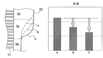
- FIG. 2 is a sectional view taken along line AA in FIG. 1. It is a figure explaining the pressure loss reduction effect in the exit header part by the intercooler for vehicles of this embodiment.
- the vehicle intercooler 1 of the present embodiment includes a core portion 10 that performs heat exchange between intake air and outside air, and an intake air introduction portion that introduces intake air from a supercharger (not shown) into the core portion 10. 20 and an intake air deriving unit 30 for deriving intake air from the core unit 10 to an engine (not shown).
- the core portion 10 has a plurality of tubes 11 that circulate intake air, a plurality of outer fins 12 interposed between the tubes 11, and a plurality of holes (not shown) that are formed through the intake upstream ends of the tubes 11.
- a vertically long inlet plate 13 that is fixed in this manner, and a vertically long outlet plate 14 that is inserted through and fixed to a plurality of holes (not shown) formed through the intake downstream end of each tube 11.
- the intake air introduction part 20 includes an inlet pipe part 21 connected to the intake pipe 41 on the supercharger side, a vertically long inlet header part 22 attached to the inlet plate 13 of the core part 10, and the inlet pipe part 21 and the inlet header.
- a curved entrance curved surface portion 23 that smoothly connects the portion 22 is provided.
- the connection position between the inlet pipe portion 21 and the inlet curved surface portion 23 is eccentric above the center position in the longitudinal direction (vertical direction) of the inlet header portion 22.
- the intake lead-out part 30 includes an outlet pipe part 31 connected to an intake pipe 42 on the engine side, a vertically long outlet header part 32 attached to the outlet plate 14 of the core part 10, and an outlet pipe part 31 and an outlet header part 32. And a curved outlet curved surface portion 33 for smoothly connecting the two.
- the connection position between the outlet pipe portion 31 and the outlet curved surface portion 33 is eccentric above the center position in the longitudinal direction (vertical direction) of the outlet header portion 32.
- the inlet header 22 includes an inlet lower hollow portion 2a formed below, an inlet upper hollow portion 2b formed above, and an inlet intermediate hollow portion connecting the inlet lower hollow portion 2a and the inlet upper hollow portion 2b. 2c.
- the inlet lower hollow portion 2a is the first inlet hollow portion of the present invention
- the inlet upper hollow portion 2b is the second inlet hollow portion of the present invention
- the inlet intermediate hollow portion 2c is the third portion of the present invention. This corresponds to the hollow portion of the inlet.
- the entrance lower hollow portion 2a is formed with a reduced cross-sectional area so that its outer wall surface does not interfere with the chassis frame 70 and peripheral parts (not shown).
- the cross-sectional area of the inlet upper hollow part 2b is formed larger than the cross-sectional area of the inlet lower hollow part 2a (about three times in this embodiment).
- the inlet intermediate hollow portion 2c is formed to have a larger cross-sectional area from the inlet lower hollow portion 2a toward the inlet upper hollow portion 2b.
- the outlet header 32 includes an outlet lower hollow portion 3a formed below, an outlet upper hollow portion 3b formed above, and an outlet intermediate hollow portion connecting the outlet lower hollow portion 3a and the outlet upper hollow portion 3b. 3c.
- the outlet lower hollow portion 3a is the first outlet hollow portion of the present invention
- the outlet upper hollow portion 3b is the second outlet hollow portion of the present invention
- the outlet intermediate hollow portion 3c is the third portion of the present invention. It corresponds to the exit hollow part of the.
- the outlet lower hollow portion 3a is formed with a reduced cross-sectional area so that its outer wall surface does not interfere with the chassis frame 70 and peripheral parts (not shown).
- the cross-sectional area of the outlet upper hollow part 3b is formed larger than the cross-sectional area of the outlet lower hollow part 3a (about 3 times in this embodiment).
- the outlet intermediate hollow portion 3c has a larger cross-sectional area as it goes from the outlet lower hollow portion 3a to the outlet upper hollow portion 3b.
- the longitudinal cross-sectional shape of the outer wall in the vehicle width direction of the inlet middle hollow portion 2c includes an inlet upper arc outer wall portion 4a protruding outward in an arc shape and an inlet lower arc outer wall portion 4b protruding inward in an arc shape. It is formed in a substantially S shape.
- the longitudinal cross-sectional shape of the outer wall in the vehicle width direction of the outlet intermediate hollow portion 3c includes an outlet upper circular arc outer wall portion 5a protruding outward in an arc shape and an outlet lower circular arc outer wall portion 5b protruding inward in an arc shape. It is formed in a substantially S shape.
- the outlet intermediate hollow portion 3c has the curvature of the outlet upper circular arc outer wall portion 5a as the inlet so that the cross-sectional area (flow channel area) rapidly expands from the outlet lower hollow portion 3a toward the outlet upper hollow portion 3b.
- the curvature is set to be larger than the curvature of the upper arc outer wall portion 4a, and the curvature of the outlet lower arc outer wall portion 5b is set to be larger than the curvature of the inlet lower arc outer wall portion 4b.
- the vertical length of the outlet intermediate hollow portion 3c is formed shorter than the inlet intermediate hollow portion 2c, and the cross-sectional area of the outlet intermediate hollow portion 3c is larger than that of the inlet intermediate hollow portion 2c with the same tube 11 as a reference. Largely formed.
- connection position of the outlet pipe portion 31 and the outlet curved surface portion 33 is eccentric above the center position in the longitudinal direction (vertical direction) of the outlet header portion 32. Therefore, after the intake air flowing through the lower tube 11 flows into the outlet lower hollow portion 3a of the outlet header portion 32 and merges, the outlet curved surface portion 33 and the outlet pipe are connected from the outlet middle hollow portion 3c via the outlet upper hollow portion 3b. Flows into the section 31.
- the outlet header portion 32 of the present embodiment is formed by rapidly expanding the cross-sectional area of the outlet intermediate hollow portion 3c, the intake air flowing into the outlet lower hollow portion 3a from the lower tube 11 receives a large resistance. And smoothly flows into the outlet intermediate hollow portion 3c. That is, as shown in FIG. 3, compared with the conventional structure that gently increases the cross-sectional area of the outlet intermediate hollow portion 3c, the cross-sectional area of the outlet upper hollow portion 3b is ensured to be large in the outlet lower hollow portion 3a. The pressure loss can be greatly reduced.
- the pressure loss in the lower region in the outlet header portion 32 can be effectively reduced, and the deterioration of the intake flow in the lower tube 11 can be reliably prevented.
- the intake air flow of each tube 11 is made uniform, and the cooling efficiency of the intake air by the core part 10 can be improved effectively.
- the cross sectional area of the outlet upper hollow portion 3b is reduced so that the cross sectional area of the outlet lower hollow portion 3a is larger than that of the outlet upper hollow portion 3b. May be formed larger.
- the cross-sectional area of the outlet intermediate hollow portion 3c may be rapidly expanded from the outlet upper hollow portion 3b toward the outlet lower hollow portion 3a.
Landscapes
- Engineering & Computer Science (AREA)
- Physics & Mathematics (AREA)
- Thermal Sciences (AREA)
- Mechanical Engineering (AREA)
- General Engineering & Computer Science (AREA)
- Chemical & Material Sciences (AREA)
- Combustion & Propulsion (AREA)
- Geometry (AREA)
- Heat-Exchange Devices With Radiators And Conduit Assemblies (AREA)
- Cooling, Air Intake And Gas Exhaust, And Fuel Tank Arrangements In Propulsion Units (AREA)
Abstract
車両用インタークーラに関し、出口ヘッダー部内の圧損を低減する。 チューブ11を有するコア部10と、入口ヘッダー部22及び偏心接続した入口パイプ部21を有する吸気導入部20と、出口ヘッダー部32及び偏心接続した出口パイプ部31を有する吸気導出部30とを備え、入口ヘッダー部22は、入口パイプ部21の反偏心側に形成した第1入口中空部2aと、偏心側に形成した第2入口中空部2bと、第2入口中空部2bに向い横断面積を大きく形成した第3入口中空部2cとを備え、出口ヘッダー部32は、出口パイプ部31の反偏心側に形成した第1出口中空部3aと、偏心側に形成した第2出口中空部3bと、第2出口中空部3bに向い横断面積を大きく形成した第3出口中空部3cとを備え、第3出口中空部3cの横断面積を第3入口中空部2cの横断面積よりも大きく形成した。
Description
本発明は、車両用インタークーラに関する。
一般的に、車両用インタークーラは、吸気を流通させる複数のチューブを車幅方向に配置したコア部と、過給機側に接続される入口パイプ部、及びコア部の吸気上流側に取り付けられる縦長の入口ヘッダー部を有する吸気導入部と、コア部の吸気下流側に取り付けられる縦長の出口ヘッダー部、及びエンジン側に接続される出口パイプ部を有する吸気導出部とを備えている。また、吸気導入部の入口パイプ部と入口ヘッダー部とは入口曲面部で連結されると共に、吸気導出部の出口ヘッダー部と出口パイプ部とは出口曲面部で連結されている。このような車両用インタークーラは、例えば特許文献1に記載されている。
ところで、吸気の冷却効率を向上するには、コア部を拡張してインタークーラを大型化することが好ましい。しかしながら、インタークーラを設置する車両のスペースはシャシフレームや周辺部品等により制約を受ける。そのため、コア部を車幅方向に拡張する場合は、シャシフレーム等との干渉を避けるべく、入口ヘッダー部や出口ヘッダー部の下方の形状を縮小させる必要がある。
特に、出口曲面部と出口パイプ部との接続位置が、出口ヘッダー部の長手方向(上下方向)中心よりも上方に偏心されている場合、下方のチューブを流れた吸気は縮小された出口ヘッダー部の下方領域に流れ込んで合流する。その結果、出口ヘッダー部内の下方領域では、圧損が増加して下方のチューブの吸気流れを悪化させる可能性がある。
本発明はこのような点に鑑みてなされたもので、その目的は、出口ヘッダー部の流路容積を大きく確保することで、出口ヘッダー部内の圧損を効果的に低減することができる車両用インタークーラを提供することにある。
上記目的を達成するため、本発明の車両用インタークーラは、エンジンへの吸気を流通させる複数のチューブを横方向に配置したコア部と、前記コア部の吸気上流側に取り付けられて前記チューブに吸気を導入する入口ヘッダー部、及び該入口ヘッダー部にその中心位置から偏心して接続された入口パイプ部を有する吸気導入部と、前記コア部の吸気下流側に取り付けられて前記チューブから吸気が流入する出口ヘッダー部、及び該出口ヘッダー部にその中心位置から偏心して接続された出口パイプ部を有する吸気導出部と、を備える車両用インタークーラにおいて、前記入口ヘッダー部は、前記入口パイプ部の偏心側とは反対側の領域に形成された第1の入口中空部と、前記入口パイプの偏心側の領域に前記第1の入口中空部よりも横断面積を大きく形成された第2の入口中空部と、前記第1の入口中空部と前記第2の入口中空部とを連結して該第2の入口中空部に向かうに従い横断面積を大きく形成された第3の入口中空部とを備え、前記出口ヘッダー部は、前記出口パイプ部の偏心側とは反対側の領域に形成された第1の出口中空部と、前記出口パイプの偏心側の領域に前記第1の出口中空部よりも横断面積を大きく形成された第2の出口中空部と、前記第1の出口中空部と前記第2の出口中空部とを連結して該第2の出口中空部に向かうに従い横断面積を大きく形成された第3の出口中空部とを備え、前記第3の出口中空部は、同一のチューブを基準として前記第3の入口中空部よりも横断面積を大きく形成された部分を有することを特徴とする。
また、前記第3の入口中空部の外壁は、縦断面形状を円弧状に形成された入口円弧外壁部を含み、前記第3の出口中空部の外壁は、縦断面形状を円弧状に形成された出口円弧外壁部を含み、前記出口円弧外壁部の曲率を前記入口円弧外壁部の曲率よりも大きく設定してもよい。
本発明の車両用インタークーラによれば、出口ヘッダー部の流路容積を大きく確保することで、出口ヘッダー部内の圧損を効果的に低減することができる。
以下、図1~3に基づいて、本発明の一実施形態に係る車両用インタークーラについて説明する。同一の部品には同一の符号を付してあり、それらの名称および機能も同じである。したがって、それらについての詳細な説明は繰返さない。
本実施形態の車両用インタークーラ1は、図1に示すように、吸気と外気との熱交換を行うコア部10と、図示しない過給機からの吸気をコア部10に導入する吸気導入部20と、コア部10から図示しないエンジンに吸気を導出する吸気導出部30とを備えている。
コア部10は、吸気を流通させる複数のチューブ11と、各チューブ11間に介装された複数のアウターフィン12と、貫通形成された図示しない複数の穴に各チューブ11の吸気上流端を挿通して固定する縦長の入口プレート13と、貫通形成された図示しない複数の穴に各チューブ11の吸気下流端を挿通して固定する縦長の出口プレート14とを備えている。
吸気導入部20は、過給機側の吸気管41に接続された入口パイプ部21と、コア部10の入口プレート13に取り付けられた縦長の入口ヘッダー部22と、入口パイプ部21と入口ヘッダー部22とを滑らかに連結する曲面状の入口曲面部23とを備えている。本実施形態において、入口パイプ部21と入口曲面部23との接続位置は、入口ヘッダー部22の長手方向(上下方向)中心位置よりも上方に偏心されている。
吸気導出部30は、エンジン側の吸気管42に接続された出口パイプ部31と、コア部10の出口プレート14に取り付けられた縦長の出口ヘッダー部32と、出口パイプ部31と出口ヘッダー部32とを滑らかに連結する曲面状の出口曲面部33とを備えている。本実施形態において、出口パイプ部31と出口曲面部33との接続位置は、出口ヘッダー部32の長手方向(上下方向)中心位置よりも上方に偏心されている。
次に、図2に基づいて、本実施形態の入口ヘッダー部22、及び出口ヘッダー部32の詳細構成を説明する。
入口ヘッダー部22は、下方に形成された入口下方中空部2aと、上方に形成された入口上方中空部2bと、これら入口下方中空部2aと入口上方中空部2bとを連結する入口中間中空部2cとを備えている。なお、本実施形態において、入口下方中空部2aは本発明の第1の入口中空部、入口上方中空部2bは本発明の第2の入口中空部、入口中間中空部2cは本発明の第3の入口中空部に相当する。
入口下方中空部2aは、その外壁面がシャシフレーム70や図示しない周辺部品と干渉しないように、横断面積を縮小して形成されている。入口上方中空部2bの横断面積は、入口下方中空部2aの横断面積よりも大きく(本実施形態では約3倍)形成されている。入口中間中空部2cは、入口下方中空部2aから入口上方中空部2bに向かうに従いその横断面積を大きく形成されている。
出口ヘッダー部32は、下方に形成された出口下方中空部3aと、上方に形成された出口上方中空部3bと、これら出口下方中空部3aと出口上方中空部3bとを連結する出口中間中空部3cとを備えている。なお、本実施形態において、出口下方中空部3aは本発明の第1の出口中空部、出口上方中空部3bは本発明の第2の出口中空部、出口中間中空部3cは本発明の第3の出口中空部に相当する。
出口下方中空部3aは、その外壁面がシャシフレーム70や図示しない周辺部品と干渉しないように、横断面積を縮小して形成されている。出口上方中空部3bの横断面積は、出口下方中空部3aの横断面積よりも大きく(本実施形態では約3倍)形成されている。出口中間中空部3cは、出口下方中空部3aから出口上方中空部3bに向かうに従いその横断面積を大きく形成されている。
入口中間中空部2cの車幅方向における外壁の縦断面形状は、外方に円弧状に突出した入口上方円弧外壁部4aと、内方に円弧状に突出した入口下方円弧外壁部4bとを備えて略S字状に形成されている。
出口中間中空部3cの車幅方向における外壁の縦断面形状は、外方に円弧状に突出した出口上方円弧外壁部5aと、内方に円弧状に突出した出口下方円弧外壁部5bとを備えて略S字状に形成されている。
本実施形態において、出口中間中空部3cは、出口下方中空部3aから出口上方中空部3bに向けて横断面積(流路面積)が急拡張するように、出口上方円弧外壁部5aの曲率を入口上方円弧外壁部4aの曲率よりも大きく設定されると共に、出口下方円弧外壁部5bの曲率を入口下方円弧外壁部4bの曲率よりも大きく設定されている。すなわち、出口中間中空部3cの上下方向の長さは、入口中間中空部2cよりも短く形成され、出口中間中空部3cの横断面積は、同一のチューブ11を基準として入口中間中空部2cよりも大きく形成されている。
次に、本実施形態に係る車両用インタークーラ1による作用効果を説明する。
吸気導出部30において、出口パイプ部31と出口曲面部33との接続位置は、出口ヘッダー部32の長手方向(上下方向)中心位置よりも上方に偏心されている。そのため、下方のチューブ11を流れた吸気は、出口ヘッダー部32の出口下方中空部3aに流れ込んで合流した後、出口中間中空部3cから出口上方中空部3bを介して出口曲面部33、出口パイプ部31に流入する。
本実施形態の出口ヘッダー部32は、出口中間中空部3cの横断面積が急拡張して形成されているので、下方のチューブ11から出口下方中空部3aに流れ込んだ吸気は、大きな抵抗を受けることなく出口中間中空部3cに円滑に流入する。すなわち、図3に示すように、出口中間中空部3cの横断面積をなだらかに増加させる従来の構造に比べて、出口上方中空部3bの横断面積を大きく確保したことで、出口下方中空部3aにおける圧損を大幅に低減することが可能になる。
したがって、本実施形態の車両用インタークーラ1によれば、出口ヘッダー部32内における下方領域の圧損を効果的に低減して、下方のチューブ11の吸気流れ悪化を確実に防止することができる。また、各チューブ11の吸気流れが均一化されて、コア部10による吸気の冷却効率を効果的に向上することができる。
なお、本発明は、上述の実施形態に限定されるものではなく、本発明の趣旨を逸脱しない範囲で、適宜変形して実施することが可能である。
例えば、シャシフレーム70や周辺部品が出口ヘッダー部32の上方側面に隣接する場合は、出口上方中空部3bの横断面積を縮小させて、出口下方中空部3aの横断面積を出口上方中空部3bよりも大きく形成してもよい。この場合は、出口中間中空部3cの横断面積を出口上方中空部3bから出口下方中空部3aに向かうに従い急拡張させればよい。
1 車両用インタークーラ
10 コア部
11 チューブ
20 吸気導入部
21 入口パイプ部
22 入口ヘッダー部
30 吸気導出部
31 出口パイプ部
32 出口ヘッダー部
2a 入口下方中空部(第1の入口中空部)
2b 入口上方中空部(第2の入口中空部)
2c 入口中間中空部(第3の入口中空部)
3a 出口下方中空部(第1の出口中空部)
3b 出口上方中空部(第2の出口中空部)
3c 出口中間中空部(第3の出口中空部)
4a 入口上方円弧外壁部(入口円弧外壁部)
5a 出口上方円弧外壁部(出口円弧外壁部)
10 コア部
11 チューブ
20 吸気導入部
21 入口パイプ部
22 入口ヘッダー部
30 吸気導出部
31 出口パイプ部
32 出口ヘッダー部
2a 入口下方中空部(第1の入口中空部)
2b 入口上方中空部(第2の入口中空部)
2c 入口中間中空部(第3の入口中空部)
3a 出口下方中空部(第1の出口中空部)
3b 出口上方中空部(第2の出口中空部)
3c 出口中間中空部(第3の出口中空部)
4a 入口上方円弧外壁部(入口円弧外壁部)
5a 出口上方円弧外壁部(出口円弧外壁部)
Claims (2)
- エンジンへの吸気を流通させる複数のチューブを横方向に配置したコア部と、前記コア部の吸気上流側に取り付けられて前記チューブに吸気を導入する入口ヘッダー部、及び該入口ヘッダー部にその中心位置から偏心して接続された入口パイプ部を有する吸気導入部と、前記コア部の吸気下流側に取り付けられて前記チューブから吸気が流入する出口ヘッダー部、及び該出口ヘッダー部にその中心位置から偏心して接続された出口パイプ部を有する吸気導出部と、を備える車両用インタークーラにおいて、
前記入口ヘッダー部は、前記入口パイプ部の偏心側とは反対側の領域に形成された第1の入口中空部と、前記入口パイプの偏心側の領域に前記第1の入口中空部よりも横断面積を大きく形成された第2の入口中空部と、前記第1の入口中空部と前記第2の入口中空部とを連結して該第2の入口中空部に向かうに従い横断面積を大きく形成された第3の入口中空部と、を備え、
前記出口ヘッダー部は、前記出口パイプ部の偏心側とは反対側の領域に形成された第1の出口中空部と、前記出口パイプの偏心側の領域に前記第1の出口中空部よりも横断面積を大きく形成された第2の出口中空部と、前記第1の出口中空部と前記第2の出口中空部とを連結して該第2の出口中空部に向かうに従い横断面積を大きく形成された第3の出口中空部と、を備え、
前記第3の出口中空部は、同一のチューブを基準として前記第3の入口中空部よりも横断面積を大きく形成された部分を有することを特徴とする車両用インタークーラ。 - 前記第3の入口中空部の外壁は、縦断面形状を円弧状に形成された入口円弧外壁部を含み、
前記第3の出口中空部の外壁は、縦断面形状を円弧状に形成された出口円弧外壁部を含み、
前記出口円弧外壁部の曲率を前記入口円弧外壁部の曲率よりも大きく設定した請求項1に記載の車両用インタークーラ。
Priority Applications (1)
| Application Number | Priority Date | Filing Date | Title |
|---|---|---|---|
| CN201380036649.2A CN104471343B (zh) | 2012-07-12 | 2013-07-11 | 车辆用中间冷却器 |
Applications Claiming Priority (2)
| Application Number | Priority Date | Filing Date | Title |
|---|---|---|---|
| JP2012-156432 | 2012-07-12 | ||
| JP2012156432A JP6056229B2 (ja) | 2012-07-12 | 2012-07-12 | 車両用インタークーラ |
Publications (1)
| Publication Number | Publication Date |
|---|---|
| WO2014010674A1 true WO2014010674A1 (ja) | 2014-01-16 |
Family
ID=49916115
Family Applications (1)
| Application Number | Title | Priority Date | Filing Date |
|---|---|---|---|
| PCT/JP2013/068989 Ceased WO2014010674A1 (ja) | 2012-07-12 | 2013-07-11 | 車両用インタークーラ |
Country Status (3)
| Country | Link |
|---|---|
| JP (1) | JP6056229B2 (ja) |
| CN (1) | CN104471343B (ja) |
| WO (1) | WO2014010674A1 (ja) |
Cited By (1)
| Publication number | Priority date | Publication date | Assignee | Title |
|---|---|---|---|---|
| JP2016176614A (ja) * | 2015-03-18 | 2016-10-06 | 象印マホービン株式会社 | 熱交換器及びそれを備える除湿機 |
Citations (6)
| Publication number | Priority date | Publication date | Assignee | Title |
|---|---|---|---|---|
| JPH01170886U (ja) * | 1988-05-18 | 1989-12-04 | ||
| JPH02124225U (ja) * | 1989-03-23 | 1990-10-12 | ||
| JPH06201291A (ja) * | 1992-12-28 | 1994-07-19 | Showa Alum Corp | 熱交換器用チューブ |
| JP2005127613A (ja) * | 2003-10-23 | 2005-05-19 | Denso Corp | 熱交換器 |
| EP1586755A2 (de) * | 2004-04-14 | 2005-10-19 | Dr.Ing. h.c.F. Porsche Aktiengesellschaft | Ladeluftkühler |
| US20120138025A1 (en) * | 2010-12-07 | 2012-06-07 | Kia Motors Corporation | Controlling method of intercooler and cooling system of vehicle |
-
2012
- 2012-07-12 JP JP2012156432A patent/JP6056229B2/ja not_active Expired - Fee Related
-
2013
- 2013-07-11 WO PCT/JP2013/068989 patent/WO2014010674A1/ja not_active Ceased
- 2013-07-11 CN CN201380036649.2A patent/CN104471343B/zh active Active
Patent Citations (6)
| Publication number | Priority date | Publication date | Assignee | Title |
|---|---|---|---|---|
| JPH01170886U (ja) * | 1988-05-18 | 1989-12-04 | ||
| JPH02124225U (ja) * | 1989-03-23 | 1990-10-12 | ||
| JPH06201291A (ja) * | 1992-12-28 | 1994-07-19 | Showa Alum Corp | 熱交換器用チューブ |
| JP2005127613A (ja) * | 2003-10-23 | 2005-05-19 | Denso Corp | 熱交換器 |
| EP1586755A2 (de) * | 2004-04-14 | 2005-10-19 | Dr.Ing. h.c.F. Porsche Aktiengesellschaft | Ladeluftkühler |
| US20120138025A1 (en) * | 2010-12-07 | 2012-06-07 | Kia Motors Corporation | Controlling method of intercooler and cooling system of vehicle |
Cited By (1)
| Publication number | Priority date | Publication date | Assignee | Title |
|---|---|---|---|---|
| JP2016176614A (ja) * | 2015-03-18 | 2016-10-06 | 象印マホービン株式会社 | 熱交換器及びそれを備える除湿機 |
Also Published As
| Publication number | Publication date |
|---|---|
| CN104471343A (zh) | 2015-03-25 |
| JP6056229B2 (ja) | 2017-01-11 |
| CN104471343B (zh) | 2017-03-08 |
| JP2014020589A (ja) | 2014-02-03 |
Similar Documents
| Publication | Publication Date | Title |
|---|---|---|
| JP6011088B2 (ja) | 車両用インタークーラ | |
| US20150129183A1 (en) | Heat exchanger having a cooler block and production method | |
| US10202880B2 (en) | Exhaust heat exchanger | |
| JP2010038477A (ja) | 熱交換用多穴チューブ | |
| JP2008298391A (ja) | 熱交換器コア熱交換器、および冷凍サイクル装置の蒸発器 | |
| JP6341530B2 (ja) | 多管式熱交換器 | |
| JP6056229B2 (ja) | 車両用インタークーラ | |
| KR101656176B1 (ko) | 대향유동 형식의 열교환기 코어 및 그 열교환기 코어를 갖는 수랭식 열교환기 및 열교환방법 | |
| JP6577282B2 (ja) | 熱交換器 | |
| JP6135057B2 (ja) | 車両用インタークーラ | |
| JP6051641B2 (ja) | 車両用インタークーラ | |
| CN110542333A (zh) | 一种高效无振动的气水换热器 | |
| JP2017172906A (ja) | 熱交換器 | |
| WO2021187371A1 (ja) | インタークーラ | |
| JP5333048B2 (ja) | 熱交換器 | |
| JP2014059123A (ja) | 熱交換器 | |
| JP2010107055A (ja) | 熱交換器 | |
| JP4629451B2 (ja) | クロスフロー型ラジエータ | |
| JP6505976B2 (ja) | Egrクーラ | |
| JP2010106723A (ja) | ハイブリッド型熱交換器 | |
| JP2009079795A (ja) | 熱交換器 | |
| JP5939167B2 (ja) | シリンダヘッド | |
| KR100644136B1 (ko) | 히터 코어의 헤더탱크 | |
| KR20180023348A (ko) | 열교환기 | |
| JP2015040641A (ja) | エバポレータ |
Legal Events
| Date | Code | Title | Description |
|---|---|---|---|
| 121 | Ep: the epo has been informed by wipo that ep was designated in this application |
Ref document number: 13816141 Country of ref document: EP Kind code of ref document: A1 |
|
| NENP | Non-entry into the national phase |
Ref country code: DE |
|
| 122 | Ep: pct application non-entry in european phase |
Ref document number: 13816141 Country of ref document: EP Kind code of ref document: A1 |