WO2014010601A1 - トラッキングデータ作成方法、及び、トラッキングデータ作成プログラム - Google Patents
トラッキングデータ作成方法、及び、トラッキングデータ作成プログラム Download PDFInfo
- Publication number
- WO2014010601A1 WO2014010601A1 PCT/JP2013/068779 JP2013068779W WO2014010601A1 WO 2014010601 A1 WO2014010601 A1 WO 2014010601A1 JP 2013068779 W JP2013068779 W JP 2013068779W WO 2014010601 A1 WO2014010601 A1 WO 2014010601A1
- Authority
- WO
- WIPO (PCT)
- Prior art keywords
- data
- gps
- time
- gps data
- robot
- Prior art date
- Legal status (The legal status is an assumption and is not a legal conclusion. Google has not performed a legal analysis and makes no representation as to the accuracy of the status listed.)
- Ceased
Links
Images






Classifications
-
- G—PHYSICS
- G01—MEASURING; TESTING
- G01S—RADIO DIRECTION-FINDING; RADIO NAVIGATION; DETERMINING DISTANCE OR VELOCITY BY USE OF RADIO WAVES; LOCATING OR PRESENCE-DETECTING BY USE OF THE REFLECTION OR RERADIATION OF RADIO WAVES; ANALOGOUS ARRANGEMENTS USING OTHER WAVES
- G01S19/00—Satellite radio beacon positioning systems; Determining position, velocity or attitude using signals transmitted by such systems
- G01S19/38—Determining a navigation solution using signals transmitted by a satellite radio beacon positioning system
- G01S19/39—Determining a navigation solution using signals transmitted by a satellite radio beacon positioning system the satellite radio beacon positioning system transmitting time-stamped messages, e.g. GPS [Global Positioning System], GLONASS [Global Orbiting Navigation Satellite System] or GALILEO
- G01S19/52—Determining velocity
-
- G—PHYSICS
- G01—MEASURING; TESTING
- G01C—MEASURING DISTANCES, LEVELS OR BEARINGS; SURVEYING; NAVIGATION; GYROSCOPIC INSTRUMENTS; PHOTOGRAMMETRY OR VIDEOGRAMMETRY
- G01C21/00—Navigation; Navigational instruments not provided for in groups G01C1/00 - G01C19/00
- G01C21/20—Instruments for performing navigational calculations
-
- G—PHYSICS
- G01—MEASURING; TESTING
- G01S—RADIO DIRECTION-FINDING; RADIO NAVIGATION; DETERMINING DISTANCE OR VELOCITY BY USE OF RADIO WAVES; LOCATING OR PRESENCE-DETECTING BY USE OF THE REFLECTION OR RERADIATION OF RADIO WAVES; ANALOGOUS ARRANGEMENTS USING OTHER WAVES
- G01S19/00—Satellite radio beacon positioning systems; Determining position, velocity or attitude using signals transmitted by such systems
- G01S19/01—Satellite radio beacon positioning systems transmitting time-stamped messages, e.g. GPS [Global Positioning System], GLONASS [Global Orbiting Navigation Satellite System] or GALILEO
- G01S19/13—Receivers
- G01S19/14—Receivers specially adapted for specific applications
Definitions
- the present invention relates to a tracking data creation method and a tracking data creation program.
- GPS Global Positioning System
- a GPS function unit As a system using this GPS, for example, in Patent Document 1 below, a GPS function unit, a holding unit that holds movement information that is information based on a plurality of longitude and latitude information acquired from the GPS function unit, and the holding
- a mobile terminal device having a transmission unit for transmitting the movement information held in the unit, an acquisition unit for acquiring the movement information transmitted from the transmission unit, and the movement information acquired by the acquisition unit
- a traceability system comprising a browsing device having a locus map display unit for displaying a movement locus of the mobile terminal device on a map based on the above is disclosed.
- the above technique merely displays a locus, and there is a problem that there is little information that can be confirmed by the user.
- the present invention has an object to provide a tracking data creation method and a tracking data creation program capable of creating tracking data that is simple and has a large amount of information.
- the tracking data creation method includes a step of reading GPS data, a step of creating speed data based on the GPS data, a step of determining a movement type based on the created speed data, Step of determining start point data and end point data from GPS data based on movement type, step of correcting error for start point data and GPS data between said end point data, start point data based on reproduction time data And adjusting the time of the GPS data between the end point data and associating the camera angle data with the GPS data between the start point data and the end point data.
- FIG. It is a figure which shows the flow of the tracking data creation method which concerns on Embodiment 1.
- FIG. It is an image figure regarding determination of a movement type. It is an image figure in the case of determining a starting point. It is a figure which shows the image of the method of error correction. It is an image figure of angle data. It is an image figure of a display image. It is the schematic of the skydiving robot which concerns on Embodiment 2.
- FIG. It is a functional block diagram of a main body robot. It is a figure which shows the other example of the robot provided with the arm. It is the schematic of the structure of a pulling amount control part. It is a figure which shows the flow of the guidance method of the skydiving robot which concerns on Embodiment 2.
- FIG. It is a figure which shows the example of a prediction path
- FIG. 1 is a diagram showing an outline of a flow of a tracking data creation method (hereinafter referred to as “the present method”) according to the present embodiment. As shown in the figure, the method includes (1) a step of reading GPS data (S1), (2) a step of creating speed data based on the GPS data (S2), and (3) movement based on the created speed data.
- the method includes (1) a step of reading GPS data (S1), (2) a step of creating speed data based on the GPS data (S2), and (3) movement based on the created speed data.
- This method is not limited as long as the above steps can be realized, but can be realized by using a so-called computer. Specifically, it can be easily realized by recording and executing a program capable of executing the above steps on a recording medium such as a hard disk of a computer.
- a recording medium such as a hard disk of a computer.
- GPS data refers to data acquired using GPS (Global Positioning System) that measures its own position by receiving radio waves from satellites. Time data and position data stored corresponding to each time data. Further, the position data includes latitude data, longitude data, and altitude data. That is, the GPS data has a plurality of combinations of time data and position data.
- GPS Global Positioning System
- this portable GPS data acquisition device includes a recording device such as a semiconductor memory and a port or terminal (eg, a USB terminal) for outputting data, and transmits / receives information to / from the port of the GPS data acquisition device.
- the cable is inserted into the port of the computer while the cable is inserted to connect them, and the GPS data stored in the recording device of the GPS data acquisition device is transmitted to the computer, or the terminal is connected to the computer port By inserting it, it becomes possible to send it to a computer.
- the GPS data is preferably stored in advance in a recording medium such as a hard disk of a computer in advance of processing, but GPS data is stored in a medium such as a CD-ROM or flash memory, You may make it read using the reader connected to the computer as needed.
- (2) velocity data is created based on GPS data.
- This speed data can be easily obtained by calculating the time between adjacent time data of GPS data and the distance between adjacent position data, and dividing this distance by time.
- the speed may be a value obtained by dividing the travel distance (straight distance between two points) in the latitude direction, longitude direction, and height direction by time, but the latitude direction, longitude direction, height It is preferable for the analysis of more detailed data to obtain for each direction, and to obtain two movement distances, a planar movement distance in the latitude and longitude directions, and a height movement distance in the height direction. It is preferable from the viewpoint of determining the movement type.
- the obtained speed data is not limited, but is preferably stored together with any one of a pair of adjacent time data and position data that is the basis of calculation.
- the step (2) of creating velocity data based on GPS data can be omitted by using it when it is obtained in advance by the GPS data acquisition device. However, this step is preferably performed in order to perform more accurate processing.
- the movement type is determined based on the created speed data.
- the “movement type” is information indicating what means the GPS acquisition target is moving, and examples of the type of movement means include skydiving, parachute, car, airplane, train, Examples include helicopters and walking.
- This moving type determination method is not limited as long as it is performed based on the created speed data.
- model data including speed data is stored in advance for each type of moving means, and this model is stored.
- the type of moving means can be determined.
- the determination of the movement type when the altitude is 10,000 m or more and the plane movement speed includes a portion having a speed of about 800 km / h, the movement by an airplane, the plane speed is 4 km / h.
- a parachute (or paraglider) can be determined.
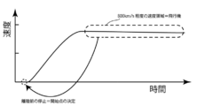
- An image diagram in this case is shown in FIG.
- a database storing a plurality of data indicating speed change profiles of speed data is provided for each type of moving means, a comparison process is performed on the time change profiles of the created speed data, and a portion showing a similar profile is included.
- start point data and end point data are determined from GPS data based on the determined movement type.
- This starting point data is a set of one time data of GPS data and its position data, and is a starting point of data processing described later.
- the end point data is a set of one time data of the GPS data and its position data, and is naturally a time later than the start point data, and is an end point of data processing described later.
- the method for determining the start point data and the end point data is not particularly limited, but when the movement type is determined, the first time data including the speed data for which the movement type can be determined and The position data may be the start point data, and the last time data and position data may be the end point data.
- the points that can be determined are often very typical parts of the moving means, and may be only a part of the whole type of moving means, so that the point is shifted by a predetermined amount.
- the GPS data time data and its position data may be used as start point data and end point data.
- the moving means when the moving means is determined, if there is a characteristic start operation and end operation for each moving means, the moving speed corresponding to the start operation or end operation is determined, and the position is set as the start point, An end point may be set, and a time point shifted from these by a predetermined time may be set as a start point and an end point. For example, in the case of an airplane, there is a stop operation of the airplane runway before a sudden speed change, so this time point or a point shifted by a predetermined time can be set as the starting point.
- the start point is the time when the data starts to fall, or the time point shifted from this time point or a predetermined time point
- the end point is the point when the height movement when landing on the ground stops or the time point shifted from the predetermined time point. Can be recognized. An image diagram in this case is shown in FIG.
- the start point and end point of profile data can be used as the start point and end point in GPS data.
- the step (3) of determining the movement type based on the created speed data and the step of (4) determining the start point data and the end point data from the GPS data based on the determined movement type are clarified.
- error correction includes not only correction of GPS data but also partial deletion or complementation of missing parts.
- a specific method for correcting the error is not limited, but for example, the following method can be adopted.
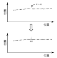
- An image diagram in this case is shown in FIG.
- Error correction can be performed by the above method. If a plurality of points are missing, it is assumed that the data is moving between two existing points at a uniform speed, and the position at each time is estimated and recorded as new position data. Is preferred. Of course, not only between two points where this data exists but also when a curve approximation can be performed before and after that point, the curve may be estimated to complement the data.
- error correction is performed at this stage, but the position of this error correction is variable. For example, it may be performed before the speed data is created based on the GPS data, or may be performed immediately thereafter. In this case, the amount of change in GPS data adjacent in time series may be calculated, and when these greatly deviate from the allowable range of the amount of change, it may be recognized that an error has occurred.
- time adjustment is performed on GPS data between the start point data and the end point data based on the reproduction time data.
- GPS data is recorded based on real time. For example, if tracking data is generated as it is when moving for a long time by an airplane or the like, it takes a very long reproduction time. On the other hand, if tracking data is generated as it is in the case of walking for a short time, a short reproduction time can be secured, but it may be felt that there is a shortage when it is desired to check the surrounding scenery slowly. Therefore, in the present embodiment, time adjustment is performed on the GPS data so that tracking data can be created at a time desired by the user of this method. Of course, if necessary, it is possible to select not to perform time adjustment. That is, “reproduction time” refers to reproduction time as tracking data.
- the specific method of this step is not limited, but accepts the input of the desired playback time data, and extends the actual time between the start point data and end point data of the GPS data to the playback time. Or it can implement
- the angle data is made to correspond to the GPS data between the start point data and the end point data.
- the angle data is data necessary for obtaining a view that can be seen by the person at the position indicated by the GPS data, and more specifically, the line of sight of the person. Data indicating the direction.
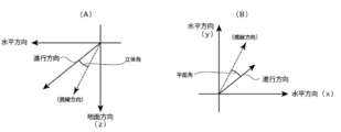
- the angle data can be divided into plane angle data indicating the angle in the plane direction (plane angle) and solid angle data indicating the solid angle (solid angle) with respect to the height direction.
- This data may be received from the user, or may be calculated or set in advance. Of course, you may set so that it may change according to a place (position) or time.
- the angle data may be an absolute angle that does not depend on the position of the GPS data so that a constant position is always displayed, but may be a relative angle determined based on the traveling direction of the GPS data. By using a relative angle, it is possible to get closer to the scenery that a moving person can actually see. Of course, it is also possible to change whether each of the plane angle and the solid angle is an absolute angle or a planar angle. An image of angle data is shown in FIG.
- the relative angle can be obtained by first determining the traveling direction and adding at least one of a plane angle and a solid angle determined as a relative angle to the angle.
- the plane angle is 0 and the solid angle is also 0.
- the method for obtaining the traveling direction indicated by the position data (current position data) in one time data is not limited, but for example, the position data of the time data immediately before the time data (the position immediately before) Data) and connecting the immediately preceding position data and the current position data, the travel direction can be obtained. In this way, the traveling direction is determined, and the line-of-sight direction can be determined by adding a relative angle thereto.
- a method for obtaining the traveling direction not only the current position data and the position data immediately before the current position data but also the position data of the immediately preceding points are determined by using a mathematical method such as a least square method. May be.
- three-dimensional mapping data refers to the actual ground surface by placing aerial photographs of the ground surface acquired by satellites, etc. along with actual position information in a virtual two-dimensional or three-dimensional space. It is also possible to use data that is open to the public by portal sites such as the Internet.
- display image data refers to data stored in a computer so as to be a display image that can be viewed through a display device by a user.
- This data includes at least a plurality of pixel data and luminance and color data corresponding to the pixel data.
- display image data is created for each time data of GPS data, and by displaying these in time series, the user can view as video.
- only one display image data and difference data of only the luminance change position of the display image data may be stored.
- the position is specified by the GPS data
- the direction of the line of sight is specified by the camera angle data
- the landscape viewed from the line of sight is recorded as display image data while referring to the mapping data.
- skydiving is known as a sport in which a person wearing a parachute or paraglider (hereinafter referred to as “parachute”) operates the parachute etc. while falling from a very high position, and lands at a target position. Yes.
- this embodiment provides a skydiving robot and its guidance system for reliably reaching a target position using the GPS function.
- the skydiving robot includes a main body robot, a canopy, a suspension line that connects the main body robot and the canopy, and a steering line that pulls the suspension line.
- the container is arrange
- FIG. 7 is a diagram showing an outline of the skydiving robot according to the present embodiment.
- the skydiving robot 1 includes at least a main body robot 2, a canopy 3, a suspension line 4, a steering line 5 that pulls the suspension line 4, and a string 6 that is connected to the steering line 5.
- a harness 7 is provided.
- a container 8 is attached to the skydiving robot 1.
- the canopy 3 is a so-called umbrella, and is a member that can adjust the speed when falling and can control the direction of falling in cooperation with the suspension line 4, the steering line 5, and the string 6. .
- the suspension line 4 is a line (string) that is connected to the canopy 3 and gathered into a bundle, and supports the main body robot 2 and the container 8 after being gathered into a bundle. At least a part thereof is connected to the steering line 5.
- the suspension line 4 is not limited, it is preferable that the suspension line 4 be bundled into two (a pair) bundles.
- the steering line 5 is connected to at least a part of the suspension lines collected in a bundle, and by pulling this line, the suspension line is drawn and the traveling direction (falling direction) ) Can be controlled.
- the suspension lines are combined into two bundles as described above, by providing each of them, it is possible to move clockwise, counterclockwise or straightly by these controls, and when both are pulled , The speed of progress can be suppressed. It is also possible to extend a part of the suspension line to be a steering line.
- the string 6 is connected to the steering line 5, and the pull amount is adjusted by the pull amount control unit of the main body robot.
- the string and the steering line may be directly connected, may be connected via a toggle (grip wheel), or may be configured as an integral member in some cases (in this case) The string becomes part of the steering line).
- the main body robot 2 is supported by the suspension line 4 via the harness 7.
- the harness 6 normally supports a human body, but in this embodiment, the harness 6 is adjusted according to its shape in order to support the main body robot.
- the container 8 is fixed by the harness 7 together with the main body robot 2.
- FIG. 8 is a functional block diagram of the main robot.
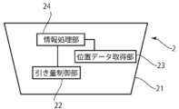
- the main robot 2 includes a housing 21, a pulling amount control unit 22 that controls pulling of a steering line and a string, a GPS data acquisition unit 23 that acquires GPS data, a pulling amount control unit 22, and a GPS.
- an information processing unit 24 connected to a GPS data acquisition unit 23 for acquiring data and performing control processing.
- the housing 21 can store the pull control unit 22, the GPS data acquisition unit 23, and the information processing unit 24, and is not limited as long as it has this function. Further, if there is a material such as a device to be placed at the target point in the main body as necessary, the material such as the device may be stored or held.
- the shape of the housing of the present embodiment is not limited, and may be a humanoid. However, in the present embodiment, the case will be described as a substantially trapezoidal box from the viewpoint of facilitating the description. In the case of a box type, there is an effect that the arrangement of the device becomes easy and a stable landing can be realized because the bottom surface is flat, and in the case of a human type, a commercially available parachute is used as it is. There is an advantage that can be done.
- the shape of the box is not particularly limited as long as it has the above function, and may be a substantially rectangular parallelepiped. Moreover, what attached the arm which can be expanded-contracted or bent to the main body may be used.
- Fig. 9 shows another image of a robot equipped with an arm.
- the steering line can be searched and gripped by itself, so that a general parachute can be used as it is.
- the arm can be easily gripped by providing a toggle (gripping member) at the tip of the steering line.
- a toggle a commercially available one can be adopted.
- the arm is provided with a camera and connected to an information processing apparatus (the information processing apparatus may be provided in the main robot) so that the arm can easily grasp the toggle.
- the information processing apparatus may be provided in the main robot
- It is also preferable to attach a marker to the toggle so that the arm is controlled after the image is captured in the vicinity of the toggle by the camera, the marker is recognized from the captured image, and the toggle is gripped.
- the pull amount control unit 22 is a control unit for pulling or extending a string (a part of the steering line when the steering line is formed integrally with the string) as described above.
- the configuration of the pull amount control unit 22 is not limited as long as described above.
- the pulley 221, the rotating shaft 222 including the motor, the motor and other members also have power. This can be realized by providing a power source 223 for supplying the power.
- the string is connected to the rotating shaft 222 via the pulley 221, and the string is wound or opened by rotating the rotating shaft 222, and the string is pulled or stretched (controlling the pulling amount). Is possible.
- the pull amount control unit 22 is not limited to this structure. As described above, when a robot with an arm is used, a portion corresponding to an arm and a hand is attached to the tip of the suspension line. It is good also as a structure hold
- the GPS data acquisition unit 23 is a member for recognizing the position of the main body robot, and is not limited, but acquires GPS data.
- GPS data is the same as in the case of acquisition of the tracking data.
- the information processing unit 24 is connected to the pull amount control unit and the GPS data acquisition unit that acquires GPS data, and performs control processing. More specifically, after acquiring the GPS data, information processing is performed, the steering line is controlled, and the main body robot is guided to the destination.
- the main body robot includes a guidance system that guides the main body robot to the destination using the above configuration.
- a guidance method for the main robot hereinafter referred to as “the present guidance method”.
- FIG. 11 is a diagram showing an outline of the flow of this guidance method.
- this guidance method (1) obtains destination data (S21), (2) obtains a plurality of GPS data every elapse of a certain time (S22), and (3) a plurality of GPS data. (S23), (4) wind direction data is acquired (S24), (5) predicted route data is acquired based on the speed data and wind direction data (S25), and (6) predicted route data
- S21 destination data
- S22 obtains a plurality of GPS data every elapse of a certain time
- S23 (4) wind direction data is acquired (S24), (5) predicted route data is acquired based on the speed data and wind direction data (S25), and (6) predicted route data
- S26 difference data of the GPS data of the main robot is acquired, the pulling control unit is controlled based on the difference data (S26), and the operations (2) to (6) are repeated until landing.
- the guidance method is not limited as long as it can be realized.
- the guidance method can be realized by storing a program for realizing the method in an information processing apparatus and executing the program.
- the above-mentioned program is stored in a recording medium such as a hard disk, read into the memory, and arithmetic processing of various data is performed by an arithmetic device such as a CPU, and data is output to the pulling control unit using this result. By doing so, the main robot can be accurately guided.
- destination data is acquired.
- the destination data is position data at a point where the main robot is to land. This destination data is input in advance before the fall starts.
- the skydiving robot is carried to a predetermined height by flying means such as a helicopter and dropped at a predetermined position.
- the skydiving robot initially performs free fall, but after falling for a predetermined distance or time, the parachute or the like is opened and the following guidance method can be executed.
- a plurality of GPS data are acquired every certain time.
- GPS data By acquiring the GPS data at every elapse of a certain time, it is possible to confirm the position of the main robot in time series and to perform the operations described later.
- About the definition of GPS data it is the same as that of said tracking data preparation method. The shorter the time interval for acquiring GPS data, the better.
- the speed data is acquired based on a plurality of GPS data.
- the acquisition of the speed data is the same as the tracking data creation method.
- the speed data can be easily obtained by calculating the time between adjacent time data of GPS data and the distance between adjacent GPS data and dividing the distance by time.
- the speed may be a value obtained by dividing the travel distance (straight distance between two points) in the latitude direction, longitude direction, and height direction by time, but the latitude direction, longitude direction, height It is preferable for the analysis of more detailed data to obtain for each direction, and to obtain two movement distances, a planar movement distance in the latitude and longitude directions, and a height movement distance in the height direction. It is more preferable to obtain and determine the wind direction data.
- the obtained speed data is not limited, but is preferably stored together with any one of a set of adjacent time data and GPS data that is the basis of calculation.
- wind direction data includes wind direction data and velocity data.
- This wind direction data can be obtained by calculation using GPS data and its velocity data.
- the pulling amount control unit is controlled to adjust the pulling amount of the string, and the robot is moved by a predetermined distance while changing the traveling direction of the robot. You may make it do.
- a difference appears between the speeds. Since this difference can be considered to be due to the wind direction, the wind direction data can be obtained by obtaining this difference.
- the ground surface when viewed directly below, it flies to form a substantially square path, and the velocity in each side direction is obtained, thereby facilitating the calculation.
- the falling speed is constant after the parachute or the like is opened, if the falling speed changes depending on the direction, it means that a component in the height direction is added to the wind direction.
- the wind direction data is acquired.
- the calculation can be performed temporarily. It can be omitted.
- Predicted route data is acquired based on speed data and wind direction data. More specifically, predicted route data is created and stored based on current GPS data, destination data, speed data, and wind direction data. As will be apparent from the description below, the predicted route data is acquired based on the current GPS data, so the position may change from moment to moment. Done.
- the predicted route is not limited as long as the robot can land on the target point. For example, when the ground plane is viewed directly below, a predetermined distance (preferably on the windward side) from the destination.
- a preferable example is a (spiral) path including a circular shape or a substantially quadrangular shape centering on a distant position.
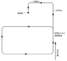
- the circular or substantially quadrilateral circular path is followed at the windward position, at a height of 600 feet, it moves to the leeward side, and at a height of 300 feet, it is approximately the direction of the wind. It is preferable that each move in a vertical direction and move upwind from a height of 300 feet to landing.
- An image diagram in this case is shown in FIG.
- the difference data between the predicted route data and the GPS data of the main robot is acquired, and the pulling control unit is controlled based on the difference data.
- difference data with respect to the GPS data of the main robot is acquired.
- the difference between the current position and the predicted route can be reduced by acquiring the difference and controlling the pull amount control unit to bring the current GPS data closer to the predicted route data.
- the present invention has industrial applicability as a tracking data creation method and a tracking data creation program.
Landscapes
- Engineering & Computer Science (AREA)
- Radar, Positioning & Navigation (AREA)
- Remote Sensing (AREA)
- Physics & Mathematics (AREA)
- General Physics & Mathematics (AREA)
- Computer Networks & Wireless Communication (AREA)
- Automation & Control Theory (AREA)
- Navigation (AREA)
- Position Fixing By Use Of Radio Waves (AREA)
Description
本発明は、トラッキングデータ作成方法、及び、トラッキングデータ作成プログラム関する。
GPS(Global Positioning System)は、GPS衛星からの信号をGPS受信機で受け取ることによって地球上における自分の位置を知ることができる非常に有用なシステムである。このシステムはカーナビゲーションシステム、携帯電話等に応用されており、現在のわれわれの生活において欠かすことのできないものとなっている。
このGPSを利用するシステムとして、例えば下記特許文献1に、GPS機能部と、前記GPS機能部から取得される複数の経度緯度情報に基づいた情報である移動情報を保持する保持部と、前記保持部に保持されている移動情報を送信するための送信部と、を有する携帯端末装置と、前記送信部から送信される移動情報を取得する取得部と、前記取得部にて取得された移動情報に基づいて前記携帯端末装置の移動軌跡を地図上に表示するための軌跡地図表示部と、を有する閲覧装置と、からなるトレーサビリティシステムが開示されている。
しかしながら、上記技術は、単に軌跡を表示するに過ぎず、使用者が確認できる情報は少ないといった課題がある。
そこで、本発明は上記課題に鑑み、簡便で情報量の多いトラッキングデータを作成することのできるトラッキングデータ作成方法、トラッキングデータ作成プログラムを提供することを目的とする。
上記課題を解決する本発明の一観点に係るトラッキングデータ作成方法は、GPSデータを読み込むステップ、GPSデータに基づき速度データを作成するステップ、作成した速度データに基づき移動タイプを決定するステップ、決定した移動タイプに基づき、GPSデータから開始点データ及び終了点データを決定するステップ、開始点データ及び前記終了点データの間のGPSデータに対しエラー修正を行うステップ、再生時間データに基づき、開始点データ及び終了点データの間のGPSデータに対し時間調整を行うステップ、開始点データ及び終了点データの間の前記GPSデータに対しカメラアングルデータを対応させるステップ、を含む。
以上、本発明により、簡便で情報量の多いトラッキングデータを作成することのできるトラッキングデータ作成方法、トラッキングデータ作成プログラムを提供することができる。
以下、本発明の実施形態について図面を用いて詳細に説明する。ただし、本発明は多くの異なる形態による実施が可能であり、以下に示す実施形態の記載例にのみ限定されるものではない。
(実施形態1:トラッキングデータ作成方法)
図1は、本実施形態に係るトラッキングデータ作成方法(以下「本方法」という。)のフローの概略を示す図である。本図で示すように、本方法は、(1)GPSデータを読み込むステップ(S1)、(2)GPSデータに基づき速度データを作成するステップ(S2)、(3)作成した速度データに基づき移動タイプを決定するステップ(S3)、(4)決定した移動タイプに基づき、GPSデータから開始点データ及び終了点データを決定するステップ(S4)、(5)開始点データ及び前記終了点データの間のGPSデータに対しエラー修正を行うステップ(S5)、(6)再生時間データに基づき、開始点データ及び終了点データの間のGPSデータに対し時間調整を行うステップ(S6)、(7)開始点データ及び終了点データの間の前記GPSデータに対しアングルデータを対応させるステップ(S7)、(8)GPSデータ、カメラアングルデータ、マッピングデータに基づき表示画像データを作成するステップ(S8)、を含む。
図1は、本実施形態に係るトラッキングデータ作成方法(以下「本方法」という。)のフローの概略を示す図である。本図で示すように、本方法は、(1)GPSデータを読み込むステップ(S1)、(2)GPSデータに基づき速度データを作成するステップ(S2)、(3)作成した速度データに基づき移動タイプを決定するステップ(S3)、(4)決定した移動タイプに基づき、GPSデータから開始点データ及び終了点データを決定するステップ(S4)、(5)開始点データ及び前記終了点データの間のGPSデータに対しエラー修正を行うステップ(S5)、(6)再生時間データに基づき、開始点データ及び終了点データの間のGPSデータに対し時間調整を行うステップ(S6)、(7)開始点データ及び終了点データの間の前記GPSデータに対しアングルデータを対応させるステップ(S7)、(8)GPSデータ、カメラアングルデータ、マッピングデータに基づき表示画像データを作成するステップ(S8)、を含む。
本方法は、上記各ステップを実現できる限りにおいて限定されるわけではないが、いわゆるコンピュータを用いることで実現可能である。具体的には、上記ステップを実行することのできるプログラムをコンピュータのハードディスク等の記録媒体に記録し、実行させることで容易に実現できる。以下、本方法については、説明をわかりやすくする観点から、コンピュータを用いた場合の例を前提として説明する。
まず、本方法ではまず、(1)GPSデータを読み込む。ここで「GPSデータ」とは、衛星からの電波を受信することによって自己の位置を計測するGPS(Global Positioning System)を用いて取得されるデータをいい、具体的には、複数の時刻データからなる時間データと、この各時刻データに対応して格納される位置データを含む。更に位置データは緯度データ、経度データ、高度データを含む。すなわち、GPSデータは、時刻データと位置データの組み合わせを複数有して構成されている。
GPSデータを取得する方法としては、様々な方法が存在するため特に限定されるわけではないが、現在携帯型のGPSデータ取得装置が市販されており、このような装置を用いることで容易に取得、記録することが可能である。特にこの携帯型のGPSデータ取得装置は、半導体メモリ等の記録装置と、データを出力するためのポート又は端子(例えばUSB端子)を備えており、上記GPSデータ取得装置のポートに情報を送受信するためのケーブルを挿入する一方コンピュータのポートにもケーブルを挿入することでこれらを接続し、GPSデータ取得装置の記録装置に格納されたGPSデータをコンピュータに送信する、又は上記端子をコンピュータのポートに差し込むことでコンピュータに送信することが可能となる。
また本実施形態において、GPSデータは、処理に先立ち、予めコンピュータのハードディスク等の記録媒体に格納しておくことが好ましいが、CD-ROMやフラッシュメモリ等のメディアにGPSデータを格納しておき、必要に応じてコンピュータに接続された読取装置を用いて読み込むようにしてもよい。
次に、本方法では、(2)GPSデータに基づき速度データを作成する。この速度データは、GPSデータの隣接する時刻データ同士の時間、隣接する位置データ同士の距離を算出し、この距離を時間で割ることで容易に求めることができる。またこの場合において、速度は、緯度方向、経度方向、高さ方向全ての移動距離(2点間の直線距離)を時間で割った値を速度としてもよいが、緯度方向、経度方向、高さ方向それぞれに対して求めておくことがより詳細なデータの解析上好ましく、また、緯度方向と経度方向の平面的な移動距離と、高さ方向における高さの移動距離の2つを求めることとしておくことが移動タイプの判断の観点から好ましい。なおこの求めた速度データは、限定されるわけではないが、計算の基礎となった隣接する時刻データと位置データの組のいずれかとともに格納しておくことが好ましい。
なお、この(2)GPSデータに基づき速度データを作成するステップは、GPSデータ取得装置により予め求められている場合、それを利用することとして、本ステップを省略することも可能である。ただし、より正確な処理を行うためにはこのステップを行っておくことが好ましい。
次に、本方法では、(3)作成した速度データに基づき移動タイプを決定する。ここで「移動タイプ」とは、GPS取得対象がどのような手段によって移動しているのかを示す情報であり、移動手段のタイプの例としては、例えばスカイダイビング、パラシュート、車、飛行機、電車、ヘリコプター、歩行等を例示することができる。
この移動タイプの決定方法は、作成した速度データに基づき行われる限りにおいて限定されるものではないが、例えば、予め移動手段のタイプ毎に、速度データを含むモデルデータを格納しておき、このモデルデータと上記速度データとを比較することで、移動手段のタイプを決定することができる。またこの場合において、緯度データ、経度データ、高度データも参照しておくことはより好ましい。例えば、この移動タイプの決定の例としては、高度が1万m以上となり平面的な移動速度が時速800km/h程度の速度となっている部分を含む場合は飛行機による移動、平面速度が時速4km程度で高度の変化があまり大きくないようであれば歩行、平面方向の移動速度に比べ高さ方向の移動速度が激しく自由落下に近い(約180km/h以上)部分を含むものであればスカイダイビング又はパラシュート(又はパラグライダー)、といった決定ができる。この場合のイメージ図を図2に示しておく。また、移動手段のタイプ毎に速度データの時間変化プロファイルを示すデータを複数格納したデータベースを備えておき、作成した速度データの時間変化のプロファイルに対し比較処理を行い、同様なプロファイルを示す部分が存在する場合、その部分が該当する移動手段であると判断することが可能となる。このようにすると、単に速度だけで抽出する場合に比べ、開始点及び終了点の抽出における誤差が生じる虞を少なくすることができるだけでなく、エラー等によって正確でない速度が算出された場合にこのようなエラーを確実に除去できるといった利点がある。
また本方法では、移動タイプを決定した後、(4)決定した移動タイプに基づき、GPSデータから開始点データ及び終了点データを決定する。この開始点データは、GPSデータのうちの一つの時刻データとその位置データの組であり、後述のデータ処理の開始点である。一方、終了点データは、GPSデータのうちの一時刻データとその位置データの組であり、当然開始点データよりも遅い時刻のものであり、後述のデータ処理の終了点である。
この開始点データ、終了点データの決定方法については、特に限定されるわけではないが、上記移動タイプを決定した場合に、その移動タイプを決定することのできた速度データを含む最初の時刻データ及び位置データを開始点データとし、最後の時刻データおよび位置データを終了点データとしてもよい。しかしながら、上記決定することのできた点は移動手段において非常に典型的な部分に過ぎない場合が多く、移動手段のタイプ全体の一部に過ぎないおそれもあるため、この点から所定の分だけずらしたGPSデータの時刻データ及びその位置データを開始点データ、終了点データとしてもよい。また、上記移動手段を決定した場合に、移動手段毎に特徴的な開始動作、終了動作が存在する場合、その開始動作又は終了動作に対応する移動速度等を判定してその位置を開始点、終了点としてもよく、更にこれらから所定の時間だけずらした時点を開始点、終了点としてもよい。例えば、飛行機であれば、急激な速度変化の前に飛行機の滑走路の停止動作が存在するためこの時点又はこれから所定の時間ずらした時点を開始点とすることもでき、パラシュートの場合は、高さデータの落下が開始された時点又はこの時点又はこれから所定の時間ずらした時点を開始点、地面に着地したときの高さ移動が停止した時点又はこれから所定の時間ずらした時点が終了点であると認識することができる。この場合のイメージ図を図3に示しておく。また、上記のように移動手段毎にプロファイルデータを備えている場合は、判断対象のデータにフィッティングさせ、プロファイルデータの開始点、終了点をGPSデータにおける開始点、終了点とすることもできる。
なお、本実施形態では上記(3)作成した速度データに基づき移動タイプを決定するステップと、(4)決定した移動タイプに基づき、GPSデータから開始点データ及び終了点データを決定するステップを明確に異なるステップとして説明しているが、同時に行うようにすることも好ましい。
また、本方法では、(5)開始点データ及び前記終了点データの間のGPSデータに対しエラー修正を行う。
GPSデータは、自動的に取得されていくものである一方、機械的なエラーにより、実際の状態と記録された状態との間に齟齬が生じている場合や、トンネル内等でGPS信号が届かないこと等を原因とするデータの欠落も少なからずある。このような場合にもそのままデータ処理を進めてしまうと現実離れした結果をもたらしてしまうこととなるため、エラー修正を行うことが好ましい。すなわち、「エラー修正」には、GPSデータの修正だけでなく一部削除や欠落した部分の補完を含む。
ここでエラー修正の具体的な方法としては、限定されるわけではないが、例えば以下で示す方法を採用することができる。この場合のイメージ図を図4に示す。
(5-1)まず、GPSデータに基づき作成された速度データを参照し、速度データが、決定した移動タイプが許容する範囲を逸脱しているか否かの判断を行う。仮に、速度データがこの範囲を逸脱している場合、エラーであると判断する。(上図)
(5-2)次に、エラーと判断されたGPSデータの時刻データはそのままとし、そのエラーと判断されたGPSの時刻データの前後の時刻データとその位置データの中間を新たな位置データとして記録する。(下図)
以上の方法によってエラー修正を行うことができる。なお、複数の点が欠如している場合は、データが存在する2点間を均一の速度で移動していると仮定し、それぞれの時間における位置を推定して新たな位置データとして記録することが好ましい。もちろん、このデータが存在する2点間だけでなく、その点の前後において曲線近似ができる場合等は、曲線を推定してデータを補完してもよい。
なお本実施形態では、エラー修正をこの段階において行っているが、このエラー修正の位置は可変である。例えば、GPSデータに基づき速度データを作成する前に行ってもよく、その後すぐに行ってもよい。この場合、時系列的に隣接するGPSデータの変化量を算出し、これらが変化量の許容範囲から大きく逸脱している場合、エラーであると認識するようにしてもよい。
さらに本方法では、(6)再生時間データに基づき、開始点データ及び終了点データの間のGPSデータに対し時間調整を行う。
実際のGPSデータは、実時間に基づくデータ記録が行われており、例えば飛行機等による長時間移動の場合にそのままトラッキングデータを作成すると、非常に長い再生時間となってしまう。一方、短時間の歩行等の場合にそのままトラッキングデータを作成すると、短い再生時間は確保できる一方で、周囲の風景をゆっくり確認したい場合には不足を感じる場合もあると考えられる。そこで、本実施形態では、GPSデータに対し時間調整を行い、本方法の使用者が望む時間でトラッキングデータを作成できるようにする。もちろん、必要によっては、時間調整を行わないとする選択も可能ではある。すなわち「再生時間」とは、トラッキングデータとしての再生時間をいう。例えば、6時間の飛行機の移動時間であった場合、ユーザーが再生時間を3分とする場合、120分の1に時間を短縮する処理を行う。一方、移動時間が再生時間よりも短い場合は、伸張する処理を行う。この場合において、GPSデータ間が長くなってしまう場合、データの間を補完する処理を行ってもよい。このようにすることでなめらかな処理が可能となる。
本ステップの具体的な方法については、限定されるわけではないが、希望の再生時間データの入力を受け付け、上記GPSデータの開始点データと終了点データの間の実時間を上記再生時間に拡大又は縮小させる処理を行うことで実現できる。
また、本方法では、(7)開始点データ及び終了点データの間のGPSデータに対しアングルデータを対応させる。
アングルデータは、GPSデータが示す位置において、その位置に居る者を想定した場合に、その者が見ることのできる景色を得るために必要なデータであり、より具体的には、その者の視線方向を示すデータである。
アングルデータは、平面方向のアングル(平面角)を示す平面アングルデータと、高さ方向に対する立体アングル(立体角)を示す立体アングルデータに分けることができる。このデータは、ユーザーからの入力を受け付けるようにしてもよいし、計算や予め独自に設定することとしてもよい。場所(位置)や時間に応じ、変化するよう設定してももちろんよい。
このアングルデータは、常に一定の位置を表示するようにGPSデータの位置によらない絶対的な角度してもよいが、GPSデータの進行方向を基準に定める相対的な角度としてもよい。相対的な角度とすることで、移動している者が実際に見ることのできる景色により近くすることができる。もちろん、平面角、立体角それぞれに絶対的な角度、平面的な角度であるかを異ならせることも可能である。なおアングルデータのイメージ図を図5に示しておく。
相対的な角度の求め方としては、まず、進行方向を定め、その角度に対して相対角度として定めた平面角及び立体角の少なくともいずれかを加算することで求めることができる。ちなみに、進行方向そのものを視線方向として採用したい場合は、平面角は0であり、立体角も0である。
なお、一つの時刻データにおける位置データ(現在の位置データ)が示す進行方向を求める方法としては、限定されるわけではないが、例えば、その時刻データの直前の時刻データの位置データ(直前の位置データ)を求め、その直前の位置データと、現在の位置データを結ぶことによって、その進行方向とすることができる。このようにすることで、進行方向が定まり、これに相対的な角度を加えることで視線方向を定めることができる。もちろん、この進行方向を求める方法として、現在の位置データとその直前の位置データを用いるだけでなく、その直前の数点の位置データを最小二乗法等の数学的手法を用いて進行方向を決定してもよい。
また、本方法では、(8)GPSデータ、カメラアングルデータ、マッピングデータに基づき表示画像データを作成する。この結果作成されるイメージ図を図6に示しておく。
ここで、「三次元マッピングデータ」とは、衛星等によって取得される地表の航空写真を、仮想の二次元又は三次元空間に実際の位置情報とともに配置していくことによって、実際の地表を再現したデータをいい、インターネット等のポータルサイト等によって一般に公開されているデータを利用することもできる。
また、本実施形態において、「表示画像データ」とは、ユーザーが表示装置を介してみることのできる表示画像となるようコンピュータに格納されるデータをいう。このデータは、少なくとも、複数の画素データと、この画素データに対応した輝度及びカラーのデータとを含む。なお、限定されるわけではないが、表示画像データはGPSデータの各々の時刻データに対し作成され、これらを時系列的に表示していくことでユーザーは映像として見ることができる。もちろん、映像とする場合においては、一の表示画像データと、この表示画像データの輝度の変化位置のみの差分データを格納することとしてもよい。
すなわち、ここでは、GPSデータで位置を特定し、カメラアングルデータによって視線方向を特定する一方、マッピングデータを参照して、その視線から見た風景を表示画像データとして記録する。そしてこれを時系列的に組み合わせることで映像として表示することができるようになる。
以上、本発明により、簡便で情報量の多いトラッキングデータを作成することのできるトラッキングデータ作成方法、トラッキングデータ作成プログラムを提供することができる。
(実施形態2:スカイダイビングロボット及び誘導システム)
ところで、スカイダイビングとは、パラシュートやパラグライダー(以下「パラシュート等」という。)を装着した人間が、非常に高い位置から落下しつつパラシュート等を操作し、目的の位置に着地するスポーツとして知られている。
ところで、スカイダイビングとは、パラシュートやパラグライダー(以下「パラシュート等」という。)を装着した人間が、非常に高い位置から落下しつつパラシュート等を操作し、目的の位置に着地するスポーツとして知られている。
しかしながら、パラシュートによって、人間が落下開始位置から確実に目的の位置に着地できるのかについては、実際に試してみなければわからないところがある一方、実際に試してみる以上人命にかかわることでもあり、試してみるとはいえ失敗は許されない。これに対し、ロボットが自動的に場所を確認し、到着することができれば非常に便利であるだけでなく、万一失敗した場合でも機械の破損程度の損失で済む。
そこで、本実施形態では、上記課題に鑑み、GPS機能を利用し、目的の位置に確実に到達するためのスカイダイビングロボット及びその誘導システムを提供する。
そのため、本実施形態の一観点にかかるスカイダイビングロボットは、本体ロボットと、キャノピーと、本体ロボットとキャノピーを接続するサスペンションラインと、サスペンションラインを引くステアリングラインと、を備える。なお、限定されるわけではないが、本体ロボットの下にはコンテナが配置されていることが好ましい。
図7は、本実施形態に係るスカイダイビングロボットの概略を示す図である。
本図で示すとおり、本実施形態に係るスカイダイビングロボット1は、少なくとも、本体ロボット2、キャノピー3、サスペンションライン4、サスペンションライン4を引くステアリングライン5と、ステアリングライン5に接続されるストリング6、ハーネス7、を備えている。また、スカイダイビングロボット1には、コンテナ8が取り付けられている。
本実施形態においてキャノピー3は、いわゆる傘であり、落下する際の速度を調節するとともに、サスペンションライン4、ステアリングライン5、ストリング6と協働して落下する方向を制御することのできる部材である。
本実施形態において、サスペンションライン4は、キャノピー3に複数接続されて束にまとめられるライン(紐)であって、束に纏められた後、本体ロボット2及びコンテナ8を支えるものである。その少なくとも一部は、ステアリングライン5に接続されている。サスペンションライン4を設けることで空中において傘を確実に広げることができ、望みの量だけ空気抵抗を得ることができるようになる。なお、サスペンションライン4は、限定されるわけではないが、二つ(一対)の束にまとめられていることが好ましい。
本実施形態において、ステアリングライン5は、上記のとおり、束にまとめられたサスペンションラインの少なくとも一部に接続されるものであり、このラインを引くことで、サスペンションラインを引き、進行方向(落下方向)を制御することが可能となる。特に、上記のように、サスペンションラインを二つの束にまとめた場合、それぞれに設けることで、これらの制御で右回り、左回り又は直進の動きを可能とすることができ、双方を引いた場合、進行速度を抑えることができる。なお、一部のサスペンションラインを延長してステアリングラインとすることも可能である。
本実施形態において、ストリング6は、ステアリングライン5に接続されるものであって、本体ロボットの引き量制御部によって引き量が調節される。なお、ストリングとステアリングラインは、直接接続されていてもよく、トグル(把持輪)を介して接続されていてもよく、また、場合によっては、一体の部材で構成されていてもよい(この場合、ストリングがステアリングラインの一部となる)。
なお、本実施形態において、キャノピー、サスペンションライン、サスペンションラインは通常市販されているものを用いることができる。すなわち、本体ロボット以外のパラシュート等の部材は、市販されているものを使用することができる。
また、本実施形態において、本体ロボット2は、サスペンションライン4にハーネス7を介して支持されている。ハーネス6は通常、人間の体を支えるものであるが、本実施形態では本体ロボットを支えるため、その形状に合わせて調整されている。また、本実施形態ではコンテナ8は、本体ロボット2ととともにハーネス7によって固定されている。
図8は、本体ロボットの機能ブロック図である。本図で示すように、本体ロボット2は、筐体21と、ステアリングライン及びストリングの引きを制御する引き量制御部22、GPSデータを取得するGPSデータ取得部23、引き量制御部22及びGPSデータを取得するGPSデータ取得部23に接続され制御処理を行う情報処理部24と、を有する。
本実施形態において筐体21は、上記引き量制御部22、GPSデータ取得部23、情報処理部24を格納することができるものであり、この機能を有する限りにおいて限定されない。また、必要に応じ、本体内に目標地点に配置したい装置等の物資がある場合、これら装置等の物資を格納又は保持するようにしてもよい。本実施形態の筐体の形状は限定されず、人型のものであってもよいが、本実施形態では説明を容易にする観点から略台形の箱として説明する。箱型である場合、装置の配置が容易になる及び底面が平面であるため安定的な着地を実現することができるといった効果があり、人型とすると、一般に市販されているパラシュートを全くそのまま使用することができるといった利点がある。この箱の形状は上記の機能を有する限りにおいて特に限定されず、略直方体であってもよい。また、本体に伸縮又は折曲自在のアームを取り付けたものであってもよい。
アームを備えたロボットの他のイメージを図9に示しておく。このようにすることで、パラシュートが開いた後、自らステアリングラインを探し、把持することが可能となるため、一般的なパラシュートをそのまま使用することができるようになる。なおこの場合、ステアリングラインの先端にトグル(把持部材)を備えさせることで、アームが把持しやすくなる。このトグルは、市販のものを採用することが可能である。またこの場合、具体的な操作としては、例えば、アームがトグルを把持しやすくなるよう、アームにカメラを備えさせるとともに情報処理装置(情報処理装置は本体ロボット内に設けてよい。)に接続し、トグルにマーカーを付すことで、カメラによるトグル近傍の画像撮影、撮影した画像からマーカー認識を行った後アームを制御し、トグルを把持させることも好ましい。
本実施形態において引き量制御部22は、上記のとおりストリング(ステアリングラインがストリングと一体に形成されている場合はステアリングラインの一部)を引く又は伸ばすための制御部である。引き量制御部22の構成は、上記の限りにおいて限定されるわけではないが、例えば、図10で示すように、プーリー221と、モーターを備える回転軸222と、モーター及び他の部材にも電力を供給する電源223を備えることで実現できる。この場合、回転軸222にプーリー221を介してストリングを接続し、回転軸222を回転させることでストリングを巻き取り、又は開放することでストリングを引く、又は伸ばすこと(引き量を制御すること)が可能となる。なおこの場合において、筐体21に直線の溝を形成し、この溝にストリングを配置することでストリングのずれを制御できるため好ましい。なお、上記のとおり引き量制御部22は、この構造に限られるものではなく、上記のように、アームが付されたロボットを用いた場合、腕及び手に相当する部分でサスペンションラインの先端に付されたトグル(把持輪)を介して保持する構成としてもよい。
GPSデータ取得部23は、本体ロボットの位置を認識するための部材であって、限定されるわけではないが、GPSデータを取得する。ここで「GPSデータ」は、上記トラッキングデータの取得の場合と同様である。
また本実施形態において、情報処理部24は、上記のとおり、引き量制御部及びGPSデータを取得するGPSデータ取得部に接続され制御処理を行うものである。より具体的には、GPSデータを取得した後、情報処理を行い、ステアリングラインを制御し、目的地まで本体ロボットを誘導する。
すなわち、本体ロボットは、上記の構成を用いて、本体ロボットを目的地まで誘導する誘導システムを備えている。ここで、本体ロボットの誘導方法(以下「本誘導方法」という。)について説明する。
図11は、本誘導方法のフローの概略を示す図である。本図で示すように、本誘導方法は、(1)目的地データを取得し(S21)、(2)GPSデータを一定時間経過毎に複数取得し(S22)、(3)複数のGPSデータに基づき速度データを取得し(S23)、(4)風向きデータを取得し(S24)、(5)速度データ、風向きデータに基づき予測経路データを取得し(S25)、(6)予測経路データと本体ロボットのGPSデータの差分データを取得し、差分データに基づき引き量制御部を制御し(S26)、更に、上記(2)から(6)の作業を着陸時まで繰り返す。
なお、本誘導方法は、実現できる限りにおいて限定されるわけではないが、例えば、情報処理装置に、上記方法を実現するためのプログラムを格納し、それを実行することによって実現できる。この場合、ハードディスク等の記録媒体に上記プログラムを格納し、これをメモリに読み込み、CPU等の演算装置によって各種データの演算処理を行わせるとともに、この結果を用いて引き量制御部にデータを出力することで本体ロボットを正確に誘導することができるようになる。
本誘導方法では、まず、(1)目的地データを取得する。目的地データとは、本体ロボットを着地させたい地点における位置データをいう。この目的地データは、落下開始前に事前に入力する。
その後、スカイダイビングロボットをヘリコプター等の飛行手段で所定の高さまで運び、所定の位置で落下させる。スカイダイビングロボットは当初自由落下を行うが、所定の距離又は時間だけ落下した後、パラシュート等を開き、以下の誘導方法を実行することができる。
まず、パラシュートが開いた後、(2)GPSデータを一定時間経過毎に複数取得する。一定時間経過毎にGPSデータを取得することで、時系列的に本体ロボットの位置を確認することができるとともに、後述の作業が可能となる。GPSデータの定義については、上記のトラッキングデータ作成方法と同様である。なおGPSデータを取得する時間間隔は短ければ短いほどよいが、データ量が膨大となり情報処理の負担が増大するため、適宜調整しておくことが好ましく、例えば10秒、30秒又は1分毎程度であることが好ましい。
次に、(3)複数のGPSデータに基づき速度データを取得する。この速度データの取得についても、上記トラッキングデータ作成方法と同様である。具体的には、この速度データは、GPSデータの隣接する時刻データ同士の時間、隣接するGPSデータ同士の距離を算出し、この距離を時間で割ることで容易に求めることができる。またこの場合において、速度は、緯度方向、経度方向、高さ方向全ての移動距離(2点間の直線距離)を時間で割った値を速度としてもよいが、緯度方向、経度方向、高さ方向それぞれに対して求めておくことがより詳細なデータの解析上好ましく、また、緯度方向と経度方向の平面的な移動距離と、高さ方向における高さの移動距離の2つを求めることとしておくことが、風向きデータを取得し、判定する上でより好ましい。なおこの求めた速度データは、限定されるわけではないが、計算の基礎となった隣接する時刻データとGPSデータの組のいずれかとともに格納しておくことが好ましい。
そして、本誘導方法では(4)風向きデータを取得する。ここで「風向きデータ」とは、風の進行方向データ及びその速度データを含む。この風向きデータは、GPSデータとその速度データを用いることで計算により取得することができる。ただし、風の進行方向データは、本体ロボットが一方向に進行し続けている状態では、その方向の算出が容易でない場合が多い。そこで、本ステップにおいては、引き量制御部を制御してストリングの引き量を調整し、本ロボットの進行方向を変えつつ所定の距離だけ移動させ、それぞれにおいて速度データを算出し、風向きデータを取得するようにしてもよい。具体的な例として、例えば、本体ロボットの進行方向を回転させて逆向きにすると、その速度同士に差分が現れる。この差分は風向きによるものと考えることができるためこの差分を求めることで風向きデータとすることができる。特に、地表面を真下に見た場合に略四角形状の経路となるよう飛行し、そのそれぞれの辺方向における速度を求めることで、その計算は容易になる。また、例えば、パラシュート等が開いた後は落下速度は一定であると仮定すると、方向によって落下速度が変わった場合は、風向きに高さ方向の成分が加わっていることを意味する。なお、本実施形態では風向きデータを取得しておくことが好ましい例として説明しているが、速度データのみでも目的地及び現在の位置が明確であれば計算は一応可能であるため、この手順を省略することは可能である。
また、本誘導方法では、(5)速度データ、風向きデータに基づき予測経路データを取得する。より具体的には、現在のGPSデータ、目的地データ、速度データ、風向きデータに基づき、予測経路データを作成し、格納する。予測経路データは後述の記載から明らかなように、現在のGPSデータに基づき取得されるものであるため、時々刻々位置が変わる場合があり、落下状況等によって大きく状況が変わる場合は、再計算が行われる。予測経路は、目標地点に本ロボットが着地できるものである限りにおいて限定されるわけではないが、例えば、地平面を真下に見た場合に、目的地から一定の距離(好ましくは風上側に)離れた位置を中心とする円形状又は略四角形状を含んでいる(スパイラルの)経路であることが好ましい一例である。具体的には、1000フィートの高さまでは風上の位置において上記円形状又は略四角形状の周回経路をたどり、600フィートの高さまでは風下側への移動、300フィートの高さまでは風向きに略垂直な方向でそれぞれ移動し、300フィートの高さから着地までは風上側への移動とすることが好ましい。この場合のイメージ図を図12に示しておく。このようにすることで、所定の高さになるまで目的地から常時同じ程度の距離を確保することができ、落下中に風向き等の状況が変わっても予測経路をすばやく再計算する等の対応が簡単に行えるという利点がある。なお、予測経路データにおいては、目的地に着地する際は、風上に向いていることが好ましい。このようにすることで、着地を容易に行うことができる。
また、本誘導方法では、(6)予測経路データと本体ロボットのGPSデータの差分データを取得し、差分データに基づき引き量制御部を制御する。予測経路データを計算した後、本体ロボットのGPSデータとの差分データを取得する。差分を取得し、引き量制御部を制御して現在のGPSデータを予測経路データに近づけることで現在の位置と予測経路との位置のずれを少なくすることができる。なお、本誘導方法では、予測経路データにおいて、本ロボットが曲がる位置に近づいた場合、差分データをとらずともストリングの引き量を制御するように指示を出すことも好ましい。また、本ロボットの落下速度が予測よりも速すぎる場合、双方のストリングを引くことで速度を落とす操作を行ってもよい。
また、本方法では、更に、上記(2)から(6)の作業を着陸時まで繰り返す。このようにすることで、時々刻々変化する状況に対して制度よく対応することができるようになる。
本発明は、トラッキングデータ作成方法、及び、トラッキングデータ作成プログラムとして産業上の利用可能性がある。
Claims (6)
- GPSデータを読み込むステップ、
前記GPSデータに基づき速度データを作成するステップ、
前記作成した速度データに基づき移動タイプを決定するステップ、
前記決定した移動タイプに基づき、前記GPSデータから開始点データ及び終了点データを決定するステップ、
前記開始点データ及び前記終了点データの間の前記GPSデータに対しエラー修正を行うステップ、
再生時間データに基づき、前記開始点データ及び前記終了点データの間の前記GPSデータに対し時間調整を行うステップ、
前記開始点データ及び前記終了点データの間の前記GPSデータに対しカメラアングルデータを対応させるステップ、を含むトラッキングデータ作成方法。 - 前記移動タイプは、パラシュート、飛行機、電車、ボート、車両、及び動物の少なくともいずれかから決定される請求項1のトラッキングデータ作成方法。
- 前記エラー修正を行うステップは、前記移動タイプに基づき行われる請求項1記載のトラッキングデータ作成方法。
- 前記エラー修正を行うステップは、前記GPSデータの補完も行う請求項1記載のトラッキングデータ作成方法。
- 再生時間データの入力を受け付けるステップ、を含む請求項1記載のトラッキングデータ作成方法。
- 前記GPSデータ、前記カメラアングルデータ、マッピングデータに基づき表示画像データを作成するステップ、
Applications Claiming Priority (6)
| Application Number | Priority Date | Filing Date | Title |
|---|---|---|---|
| US201261670069P | 2012-07-10 | 2012-07-10 | |
| US61670069 | 2012-07-10 | ||
| US201261671805P | 2012-07-16 | 2012-07-16 | |
| US61671805 | 2012-07-16 | ||
| US201261728113P | 2012-11-19 | 2012-11-19 | |
| US61728113 | 2012-11-19 |
Publications (1)
| Publication Number | Publication Date |
|---|---|
| WO2014010601A1 true WO2014010601A1 (ja) | 2014-01-16 |
Family
ID=49916053
Family Applications (1)
| Application Number | Title | Priority Date | Filing Date |
|---|---|---|---|
| PCT/JP2013/068779 Ceased WO2014010601A1 (ja) | 2012-07-10 | 2013-07-09 | トラッキングデータ作成方法、及び、トラッキングデータ作成プログラム |
Country Status (1)
| Country | Link |
|---|---|
| WO (1) | WO2014010601A1 (ja) |
Cited By (1)
| Publication number | Priority date | Publication date | Assignee | Title |
|---|---|---|---|---|
| JP2017097720A (ja) * | 2015-11-26 | 2017-06-01 | Necソリューションイノベータ株式会社 | 航跡描画装置、航跡描画方法、及びプログラム |
Citations (4)
| Publication number | Priority date | Publication date | Assignee | Title |
|---|---|---|---|---|
| WO2005038402A1 (ja) * | 2003-10-21 | 2005-04-28 | Waro Iwane | ナビゲーション装置 |
| JP2006080737A (ja) * | 2004-09-08 | 2006-03-23 | Noritsu Koki Co Ltd | ナビゲーションアルバムシステム |
| JP2006092032A (ja) * | 2004-09-21 | 2006-04-06 | National Agriculture & Bio-Oriented Research Organization | トレーサブルナビゲーションシステム |
| JP2012207998A (ja) * | 2011-03-29 | 2012-10-25 | Fujitsu Ten Ltd | 情報処理装置、情報処理方法、及び、プログラム |
-
2013
- 2013-07-09 WO PCT/JP2013/068779 patent/WO2014010601A1/ja not_active Ceased
Patent Citations (4)
| Publication number | Priority date | Publication date | Assignee | Title |
|---|---|---|---|---|
| WO2005038402A1 (ja) * | 2003-10-21 | 2005-04-28 | Waro Iwane | ナビゲーション装置 |
| JP2006080737A (ja) * | 2004-09-08 | 2006-03-23 | Noritsu Koki Co Ltd | ナビゲーションアルバムシステム |
| JP2006092032A (ja) * | 2004-09-21 | 2006-04-06 | National Agriculture & Bio-Oriented Research Organization | トレーサブルナビゲーションシステム |
| JP2012207998A (ja) * | 2011-03-29 | 2012-10-25 | Fujitsu Ten Ltd | 情報処理装置、情報処理方法、及び、プログラム |
Cited By (1)
| Publication number | Priority date | Publication date | Assignee | Title |
|---|---|---|---|---|
| JP2017097720A (ja) * | 2015-11-26 | 2017-06-01 | Necソリューションイノベータ株式会社 | 航跡描画装置、航跡描画方法、及びプログラム |
Similar Documents
| Publication | Publication Date | Title |
|---|---|---|
| US10648809B2 (en) | Adaptive compass calibration based on local field conditions | |
| US10942528B2 (en) | Return path configuration for remote controlled aerial vehicle | |
| US20210116943A1 (en) | Systems and methods for uav interactive instructions and control | |
| US10831186B2 (en) | System for authoring, executing, and distributing unmanned aerial vehicle flight-behavior profiles | |
| US12282989B2 (en) | Map view | |
| US20210341527A1 (en) | Unmanned Aerial Vehicle Electromagnetic Avoidance And Utilization System | |
| US10816967B2 (en) | Magic wand interface and other user interaction paradigms for a flying digital assistant | |
| US9409656B2 (en) | Aerial photographing system | |
| CN104035446B (zh) | 无人机的航向生成方法和系统 | |
| JP2010202178A5 (ja) | ||
| US20160054737A1 (en) | Methods and Apparatus for Unmanned Aerial Vehicle Autonomous Aviation | |
| US20160327389A1 (en) | Calibration Transfer Between Two Devices | |
| CN111465556B (zh) | 信息处理系统、信息处理方法及电脑可读存储媒体 | |
| CN108496130A (zh) | 飞行控制方法、设备、控制终端及其控制方法、无人机 | |
| RU2687008C2 (ru) | Способ установления плановой траектории полета транспортного средства возле цели (варианты), вычислительное устройство (варианты) | |
| JP6957304B2 (ja) | 架線撮影システム及び架線撮影方法 | |
| US20210208214A1 (en) | Magnetic sensor calibration method and mobile platform | |
| JP2017036988A (ja) | 撮影システム | |
| CN111699454A (zh) | 一种飞行规划方法及相关设备 | |
| WO2014010601A1 (ja) | トラッキングデータ作成方法、及び、トラッキングデータ作成プログラム | |
| US12387483B2 (en) | Systems, methods, and apparatus for testing UAV devices | |
| US20250328449A1 (en) | Flight Software Testing Using Actual Flight Data |
Legal Events
| Date | Code | Title | Description |
|---|---|---|---|
| 121 | Ep: the epo has been informed by wipo that ep was designated in this application |
Ref document number: 13816572 Country of ref document: EP Kind code of ref document: A1 |
|
| NENP | Non-entry into the national phase |
Ref country code: DE |
|
| 122 | Ep: pct application non-entry in european phase |
Ref document number: 13816572 Country of ref document: EP Kind code of ref document: A1 |
|
| NENP | Non-entry into the national phase |
Ref country code: JP |