WO2014010600A1 - 湾曲板の製造方法 - Google Patents
湾曲板の製造方法 Download PDFInfo
- Publication number
- WO2014010600A1 WO2014010600A1 PCT/JP2013/068776 JP2013068776W WO2014010600A1 WO 2014010600 A1 WO2014010600 A1 WO 2014010600A1 JP 2013068776 W JP2013068776 W JP 2013068776W WO 2014010600 A1 WO2014010600 A1 WO 2014010600A1
- Authority
- WO
- WIPO (PCT)
- Prior art keywords
- glass plate
- tempered glass
- curved
- plate
- tensile stress
- Prior art date
- Legal status (The legal status is an assumption and is not a legal conclusion. Google has not performed a legal analysis and makes no representation as to the accuracy of the status listed.)
- Ceased
Links
Images







Classifications
-
- C—CHEMISTRY; METALLURGY
- C03—GLASS; MINERAL OR SLAG WOOL
- C03B—MANUFACTURE, SHAPING, OR SUPPLEMENTARY PROCESSES
- C03B33/00—Severing cooled glass
- C03B33/02—Cutting or splitting sheet glass or ribbons; Apparatus or machines therefor
- C03B33/04—Cutting or splitting in curves, especially for making spectacle lenses
-
- C—CHEMISTRY; METALLURGY
- C03—GLASS; MINERAL OR SLAG WOOL
- C03B—MANUFACTURE, SHAPING, OR SUPPLEMENTARY PROCESSES
- C03B33/00—Severing cooled glass
- C03B33/09—Severing cooled glass by thermal shock
- C03B33/091—Severing cooled glass by thermal shock using at least one focussed radiation beam, e.g. laser beam
-
- C—CHEMISTRY; METALLURGY
- C03—GLASS; MINERAL OR SLAG WOOL
- C03B—MANUFACTURE, SHAPING, OR SUPPLEMENTARY PROCESSES
- C03B23/00—Re-forming shaped glass
- C03B23/02—Re-forming glass sheets
- C03B23/023—Re-forming glass sheets by bending
-
- C—CHEMISTRY; METALLURGY
- C03—GLASS; MINERAL OR SLAG WOOL
- C03B—MANUFACTURE, SHAPING, OR SUPPLEMENTARY PROCESSES
- C03B23/00—Re-forming shaped glass
- C03B23/02—Re-forming glass sheets
- C03B23/023—Re-forming glass sheets by bending
- C03B23/025—Re-forming glass sheets by bending by gravity
- C03B23/0252—Re-forming glass sheets by bending by gravity by gravity only, e.g. sagging
- C03B23/0254—Re-forming glass sheets by bending by gravity by gravity only, e.g. sagging in a continuous way, e.g. gravity roll bending
-
- C—CHEMISTRY; METALLURGY
- C03—GLASS; MINERAL OR SLAG WOOL
- C03B—MANUFACTURE, SHAPING, OR SUPPLEMENTARY PROCESSES
- C03B27/00—Tempering or quenching glass products
- C03B27/04—Tempering or quenching glass products using gas
- C03B27/0422—Tempering or quenching glass products using gas for flat or bent glass sheets starting in an horizontal position and ending in a non-horizontal position
- C03B27/0426—Tempering or quenching glass products using gas for flat or bent glass sheets starting in an horizontal position and ending in a non-horizontal position for bent glass sheets
Definitions
- the present invention relates to a method for manufacturing a curved plate.
- the tempered glass plate is one in which residual compressive stress is generated on the front and back surfaces of the glass plate and the front and back surfaces of the glass plate are strengthened.
- a curved plate which is a bending tempered glass plate, has been manufactured by cutting a glass plate into a product size, bending it, and then strengthening (for example, patents) Reference 1).
- FIG. 1 is an explanatory view (1) of glass sheet bending.
- FIG. 2 is a cross-sectional view showing the glass plate of FIG.
- a tensile stress is generated along the curved surface 2 of the glass plate 1
- a compressive stress corresponding to the tensile stress and Poisson's ratio is generated. Occurs in a direction perpendicular to the curve.
- compressive stress is generated along the curve
- tensile stress corresponding to the compressive stress and Poisson's ratio is generated in a direction perpendicular to the curve.
- both ends 1a and 1b of the glass plate 1 warp in unintended directions as shown in FIG.
- the both ends 1a and 1b of the glass plate 1 are warped because the end of the glass plate 1 is a free end and thus is more freely movable than the inside of the glass plate 1.
- FIG. 3 is an explanatory diagram (2) of glass sheet bending.
- the glass plate 1 is bent while the glass plate 1 softened by heating is conveyed by a plurality of conveying rollers 4.
- the plurality of transport rollers 4 form a curved upwardly inclined transport path. Since the front end 1c and the rear end 1d of the glass plate 1 are free ends, bending stress is hardly generated at the front end 1c and the rear end 1d, and insufficient bending is likely to occur at the front end 1c and the rear end 1d.
- FIG. 4 is an explanatory view (3) of the bending forming of the glass plate.
- the plurality of conveyance rolls 4 are moved up and down so that the conveyance path of the glass plate 1 becomes a traveling wave. Similar to the method of FIG. 3, this method also tends to cause insufficient bending at the front end 1c and the rear end 1d of the glass plate 1.
- FIG. 5 is an explanatory view (4) of glass sheet bending.
- the glass plate 1 is, for example, a vehicle window glass
- the through hole 1e is, for example, a wiper hole.
- FIG. 6 is an explanatory view (5) of the bending of the glass plate. As shown in FIG. 6, when a part of the outer periphery of the glass plate 1 is recessed, the convex portion 1g of the glass plate 1 is unlikely to generate bending stress and is likely to be insufficiently bent.
- the glass plate 1 is, for example, a vehicle window glass.
- a bent plate which is a bending tempered glass plate, was manufactured by cutting a glass plate into a product size, bending it, and then strengthening it.
- problems such as warping and insufficient bending occur as described above, and it is difficult to obtain a curved plate having a desired shape.
- the present invention has been made in view of the above problems, and an object of the present invention is to provide a method of manufacturing a curved plate capable of obtaining a desired shape.
- a method for manufacturing a curved plate includes: A molding process for bending a glass sheet softened by heating; Front and back layers as reinforcing layers having a residual compressive stress by reinforcing the front and back surfaces of the bent glass plate, and an intermediate layer having an internal residual tensile stress formed between the front and back layers
- a tempering step for producing a tempered glass plate comprising: Moving the irradiation position of the laser light in the tempered glass plate, extending a crack penetrating the tempered glass plate in the thickness direction, and cutting the curved plate from the tempered glass plate, In the cutting step, the intermediate layer is locally heated by the laser light at a temperature below the annealing point, and a tensile stress or a compressive stress smaller than the internal residual tensile stress is locally generated in the intermediate layer. The crack extension speed due to the internal residual tensile stress is controlled.
- a method for manufacturing a curved plate capable of obtaining a desired shape.
- FIG. 12 is a schematic diagram showing an example of a stress distribution in a cross section along the line AA in FIG. 11.
- FIG. 12 is a schematic diagram showing an example of a stress distribution in a cross section along the line BB in FIG. 11.
- the manufacturing method of the curved plate which is a bending strengthening glass plate has a formation process, a reinforcement
- a glass plate softened by heating is bent.
- bending methods such as roll forming shown in FIGS. 3 and 4, gravity forming in which the outer periphery of the glass plate is supported by a ring, and the glass plate is bent by its own weight, and the glass plate is pressed against the mold.
- Any of press forming that bends along a vacuum and vacuum forming that a glass plate is vacuum-adsorbed with a mold and bent along the mold may be used.
- These molding methods can also be used in combination. For example, a combination of press molding and vacuum molding, a combination of press molding and gravity molding, or the like is possible.
- the strengthening method may be either a physical strengthening method such as an air cooling strengthening method or a chemical strengthening method such as an ion exchange method.
- the air-cooling strengthening method rapidly cools the glass plate at the temperature near the softening point from both sides, and creates a temperature difference between the front and back surfaces of the glass plate and the inside of the glass plate. Residual compressive stress is generated, and the front and back surfaces of the glass plate are strengthened.
- the front and back surfaces of a glass plate are ion-exchanged, and ions having a small ion radius (for example, Li ions and Na ions) contained in the glass are replaced with ions having a large ion radius (for example, K ions).
- ions having a small ion radius for example, Li ions and Na ions
- K ions for example, K ions
- the type of glass on the glass plate is not particularly limited, and examples thereof include soda lime glass and non-alkali glass.
- the thickness of the glass plate is appropriately set according to the use of the glass plate, and is, for example, 0.1 to 25 mm. In the case of a tempered glass plate by physical strengthening, it is preferable that the thickness is 1.5 mm or more because a temperature difference is easily made between the front and back surfaces of the glass plate and the inside in the strengthening step.
- FIG. 7 is a diagram showing an example of a cross section of a tempered glass plate.
- the direction of the arrow indicates the acting direction of the residual stress
- the size of the arrow indicates the magnitude of the stress.
- the tempered glass plate 10 includes a surface layer 13 and a back surface layer 15 as a reinforced layer having a residual compressive stress, and an intermediate layer 17 formed between the surface layer 13 and the back surface layer 15 and having a residual tensile stress.
- the end surface of the tempered glass plate 10 may be covered with a reinforcing layer extending from the end of the surface layer 13 and the end of the back surface layer 15. Further, the end face of the tempered glass plate 10 may not be covered with the tempered layer, and the end face of the intermediate layer 17 may be exposed at the end face of the tempered glass plate 10.
- FIG. 8 is a schematic diagram showing an example of the residual stress distribution of the air-cooled tempered glass sheet.
- FIG. 9 is a schematic diagram showing an example of a residual stress distribution of a chemically strengthened glass plate.
- the residual compressive stress decreases from the both ends in the thickness direction of the tempered glass plate 10 toward the inside, and the residual tensile stress is generated inside the tempered glass plate 10.
- CS is the maximum residual compressive stress (surface compressive stress) (> 0) of the reinforcing layers 13 and 15
- CT is the internal residual tensile stress (> 0) in the intermediate layer 17
- DOL is the reinforcing layer 13
- a thickness of 15 is shown respectively.
- CS, CT, and DOL are the tempering conditions (in the case of air-cooled tempering method, the heating temperature and cooling rate of the glass plate, in the case of ion exchange method, the concentration and temperature of the processing solution, and the glass plate to the processing solution The immersion time can be adjusted.
- the surface compressive stress (CS) of the reinforcing layers 13 and 15 and the thickness (DOL) of the reinforcing layers 13 and 15 are measured by, for example, a surface stress meter FSM-6000 (manufactured by Orihara Seisakusho).
- CT (CS ⁇ DOL) / (t ⁇ 2 ⁇ DOL) (1)
- CT (CS ⁇ DOL) / (t ⁇ 2 ⁇ DOL) (1)
- C1 represents the maximum residual compressive stress of the surface layer 13
- D1 represents the thickness of the surface layer 13
- C2 represents the maximum residual compressive stress of the back surface layer 15
- D2 represents the thickness of the back surface layer 15.
- CT CS / a (3)
- a a constant determined by the temperature at the time of starting the cooling of the glass plate, the cooling rate of the glass, the thickness of the glass plate, and is usually in the range of 2.0 to 2.5.
- FIG. 10 is an explanatory diagram of the cutting process according to the first embodiment.
- FIG. 11 is a diagram illustrating an example of the relationship between the irradiation position of the laser beam on the tempered glass plate and the tip position of the crack.
- the curved plate is cut out from the tempered glass plate 10.
- the curved plate may be at least partially curved, and may be partially flat.
- the tempered glass plate 10 is irradiated with the laser beam 20 locally, and the laser beam 20 on the tempered glass plate 10 is irradiated.
- the crack 30 penetrating the tempered glass plate 10 in the thickness direction is extended.
- the crack 30 extends along the locus of the irradiation position of the laser beam 20 on the tempered glass plate 10.
- the tempered glass plate 10 may move, the light source of the laser beam 20 may move, or both may move.
- the tempered glass plate 10 may be rotated. Further, in order to move the irradiation position of the laser beam 20 on the tempered glass plate 10, a galvanometer mirror that reflects the laser beam from the light source toward the tempered glass plate 10 may be rotated.
- the crack 30 penetrates the tempered glass plate 10 in the thickness direction, and the cutting of this embodiment is a so-called full cut cutting.
- the scribe line may not be formed at the cutting position of the tempered glass plate 10 before the laser irradiation.
- a scribe line may be formed, but it takes time to form the scribe line.
- the tempered glass board 10 may be missing when forming the scribe line.
- An initial crack may be formed at the cutting start position of the tempered glass plate 10.
- the initial crack is formed by, for example, a cutter, a file, or a laser.
- microcracks formed by grinding can be used as initial cracks.
- the cutting start position and the cutting end position of the tempered glass plate 10 may be either the outer periphery of the tempered glass plate 10 or the inside of the tempered glass plate 10. Moreover, the shape of the cutting line of the tempered glass plate 10 may be various.
- Laser light 20 is emitted from a light source, then condensed by an optical system such as a condenser lens, is incident on the front surface 12 of the tempered glass plate 10, and is emitted from the rear surface 14 of the tempered glass plate 10.
- an optical system such as a condenser lens
- the tempered glass plate 10 While the laser beam 20 passes through the tempered glass plate 10, the tempered glass plate 10 absorbs part of the irradiation energy of the laser beam 20 as heat, and thermal stress is generated in the tempered glass plate 10. Using this thermal stress, cutting of the tempered glass plate 10 is controlled.
- the cutting mechanism of the tempered glass plate 10 and the cutting of the non-tempered glass of the present embodiment are fundamentally different, and the way of crack extension is completely different.
- the glass plate In cutting the non-strengthened glass plate, the glass plate is locally heated with laser light, and the irradiation position of the laser light on the glass plate is moved to form a temperature gradient along the moving direction. A tensile stress is generated in the vicinity of the rear of the irradiation position of the laser beam, and the crack extends due to this tensile stress.
- the tip position of the crack follows the irradiation position of the laser light as the irradiation position of the laser light moves.
- the extension of the crack is performed only by the irradiation energy of the laser beam. Therefore, if laser irradiation is interrupted in the middle of cutting, the extension of cracks stops.
- the tensile stress is not generated by laser light as in the case of cutting of non-tempered glass. May be.
- the crack extends by itself due to residual tensile stress.
- the crack can extend in any direction. Further, when the crack extension speed reaches a certain speed, the crack branches.
- CT internal residual tensile stress
- the intermediate layer 17 is locally heated at a temperature equal to or lower than the annealing point by the laser light 20 while cutting the tempered glass plate 10 by extending the crack 30 due to the internal residual tensile stress CT.
- a tensile stress or a compressive stress smaller than the internal residual tensile stress CT is locally generated in the intermediate layer 17 to suppress the extension of the crack 30 due to the internal residual tensile stress CT. That is, the extension speed of the crack 30 can be controlled by controlling the moving speed of the irradiation position of the laser beam 20. By controlling the extension speed of the crack 30, the direction in which the crack 30 extends can be determined, and the crack 30 can be prevented from branching.
- the extension locus of the crack 30 can be controlled with high accuracy.
- the reason why the intermediate layer 17 is heated at a temperature equal to or lower than the annealing point is that when the heating exceeds the annealing point, the thermal stress is relieved by the viscous flow of the glass plate.
- FIG. 12 is a schematic diagram showing an example of a stress distribution in a cross section along the line AA in FIG.
- FIG. 13 is a schematic diagram showing an example of a stress distribution in a cross section along the line BB in FIG.
- the cross section in FIG. 13 is a cross section behind the cross section in FIG.
- “rear” means the rear in the moving direction of the irradiation position of the laser light on the tempered glass plate (that is, the rearward direction of the crack in the tempered glass plate). 12 and 13, the direction of the arrow indicates the direction of the applied stress, and the length of the arrow indicates the magnitude of the stress.
- the laser-irradiated portion of the intermediate layer 17 is heated to a higher temperature than other portions of the intermediate layer 17. Therefore, a tensile stress or a compressive stress smaller than the internal residual tensile stress CT is generated in the laser irradiated portion of the intermediate layer 17, and the extension of the crack 30 due to the internal residual tensile stress CT is suppressed. If compressive stress is generated as shown in FIG. 12, extension of the crack 30 can be reliably prevented. On the other hand, when a tensile stress smaller than the internal residual tensile stress CT is generated, the tip position of the crack 30 and the irradiation position of the laser beam 20 are close to each other, and the tip position of the crack 30 can be accurately controlled.
- the rear vicinity of the laser irradiation portion of the intermediate layer 17 is lower in temperature than the laser irradiation portion of the intermediate layer 17. Therefore, a tensile stress larger than the internal residual tensile stress CT is generated in the vicinity of the rear of the laser irradiation portion of the intermediate layer 17.
- the crack 30 is formed in a portion where the tensile stress exceeds a predetermined value, and is concentrated in a portion where the tensile stress is large. Therefore, the tip position of the crack 30 does not deviate from the locus of the irradiation position of the laser beam 20.
- the tip position of the crack 30 follows the irradiation position of the laser beam 20 as the irradiation position of the laser beam 20 moves, and does not pass the irradiation position of the laser beam 20.
- the tip position of the crack 30 may partially overlap the irradiation position of the laser light 20 as long as it does not pass the irradiation position of the laser light 20.
- the intermediate layer 17 is locally heated by the laser beam 20, and a tensile stress or a compressive stress smaller than the internal residual tensile stress CT is locally generated in the intermediate layer 17,
- the extension of the crack 30 due to the internal residual tensile stress CT is suppressed. Therefore, the tip position of the crack 30 can be controlled with high accuracy, and the cutting accuracy can be improved.
- the laser light 20 having a high internal transmittance is used.
- ⁇ ⁇ M is 3.0 or less (that is, the internal transmittance of the laser light is 5% or more). It is preferable.
- ⁇ ⁇ M By setting ⁇ ⁇ M to 3.0 or less, most of the irradiation energy of the laser light 20 is prevented from being absorbed as heat in the vicinity of the surface 12 of the tempered glass plate 10, and a steep temperature gradient in the plate thickness direction. Can be prevented well. This prevents the laser irradiation portion of the surface layer 13 from becoming significantly hotter than the laser irradiation portion of the intermediate layer 17 and prevents a tensile stress larger than the internal residual tensile stress CT from being generated in the laser irradiation portion of the intermediate layer 17. Can be prevented. Therefore, it is possible to prevent the tip position of the crack 30 from overtaking the irradiation position of the laser light 20.
- ⁇ ⁇ M is more preferably 0.3 or less (laser light internal transmittance of 74% or more), further preferably 0.105 or less (laser light internal transmittance of 90% or more), and particularly preferably 0.02 or less. (Internal transmittance of laser beam is 98% or more).
- the internal residual tensile stress CT is preferably 15 MPa or more so that the extension of the crack 30 is mainly performed by the residual tensile stress of the intermediate layer 17. Thereby, the position where the tensile stress reaches a predetermined value (that is, the tip position of the crack 30) and the irradiation position of the laser beam 20 are sufficiently close, and the cutting accuracy is improved.
- the internal residual tensile stress CT is more preferably 30 MPa or more, and further preferably 40 MPa. When the internal residual tensile stress CT is 30 MPa or more, the crack 30 extends only by the residual tensile stress of the intermediate layer 17, and the tip position of the crack 30 and the irradiation position of the laser beam 20 become closer, so that the cutting accuracy is improved. Further improve.
- a near infrared (hereinafter simply referred to as “near infrared”) laser having a wavelength of 800 to 1100 nm is used.
- the near-infrared laser for example, a Yb fiber laser (wavelength: 1000 to 1100 nm), a Yb disk laser (wavelength: 1000 to 1100 nm), an Nd: YAG laser (wavelength: 1064 nm), a high-power semiconductor laser (wavelength: 808 to 980 nm) ).
- These near-infrared lasers are high-powered and inexpensive, and it is easy to adjust ⁇ ⁇ M within a desired range.
- a high-power and inexpensive near-infrared laser is used as the light source of the laser light 20, but any light source having a wavelength of 250 to 5000 nm may be used.
- any light source having a wavelength of 250 to 5000 nm may be used.
- UV laser wavelength: 355 nm
- green laser wavelength: 532 nm
- Ho: YAG laser wavelength: 2080 nm
- Er YAG laser (2940 nm)
- laser using a mid-infrared light parametric oscillator (wavelength: 2600) To 3450 nm).
- the oscillation method of the laser beam 20 is not limited, and either a CW laser that continuously oscillates the laser beam or a pulse laser that oscillates the laser beam intermittently can be used.
- the intensity distribution of the laser beam 20 is not limited, and may be a Gaussian type or a top hat type.
- the absorption coefficient ⁇ increases as the content of iron (Fe), cobalt (Co), and copper (Cu) in the tempered glass plate 10 increases. Becomes larger. In this case, the absorption coefficient ⁇ increases in the vicinity of the absorption wavelength of the rare earth atom as the content of the rare earth element (for example, Yb) in the tempered glass plate 10 increases.
- the adjustment of the absorption coefficient ⁇ uses iron from the viewpoint of glass transparency and cost, and cobalt, copper, and rare earth elements may not be substantially contained in the tempered glass plate 10.
- the intensity of the laser beam 20 is attenuated according to Lambert-Beer's law. Therefore, the front surface 12 and the back surface 14 of the tempered glass plate 10 have the same or substantially the same laser power density (W / cm 2 ), that is, the same or substantially the same temperature.
- the area of the laser beam 20 may be smaller than the area of the laser beam 20 on the surface 12. If the condensing position of the laser beam 20 is on the side opposite to the light source with respect to the tempered glass plate 10, the area of the laser beam 20 on the back surface 14 is smaller than the area of the laser beam 20 on the front surface 12. If the temperatures of the front surface 12 and the back surface 14 of the tempered glass plate 10 are approximately the same, the cracks 30 extend to the same extent on the front surface 12 and the back surface 14 of the tempered glass plate 10.
- the condensing position of the laser beam 20 may be inside the tempered glass plate 10 or may be on the light source side with reference to the tempered glass plate 10 as shown in FIG.
- the laser beam 20 may be formed in a circle having a diameter ⁇ smaller than the plate thickness t of the tempered glass plate 10.
- the diameter ⁇ smaller than the plate thickness t, the heated portion of the glass plate 10 does not become too large, and a part of the cut surface (particularly, the cutting start portion and the cutting end portion) is prevented from being slightly curved. it can.
- the shape of the laser beam 20 on the surface 12 of the tempered glass plate 10 may be various, and may be, for example, a rectangle or an ellipse.
- Examples of uses of the curved plate cut out from the tempered glass plate 10 in the cutting process include vehicle window glass, architectural window glass, curved mirrors for solar power generation (Concentrated Solar thermal ⁇ Power), portable devices such as mobile phones and laptop computers. And the like.
- FIG. 14 is a diagram showing an example of the cutout position of the curved plate cut out from the tempered glass plate.
- the portion of the curved plate cut out from the tempered glass plate is indicated by oblique lines.
- the curved plates 101, 102, and 103 can be cut out from a portion of the tempered glass plate 10 that is free from problems such as unintended warping and insufficient bending. Therefore, a curved plate having a desired shape can be obtained.
- the curved plate 101 having the desired shape is obtained by cutting off the end of the tempered glass plate 10 as a portion having a problem such as unintentional warping or insufficient bending.
- the curved plate 102 having a desired shape is obtained by cutting the outer peripheral portion of the tempered glass plate 10 as a defective portion.
- the outer peripheral portion of the tempered glass plate 10 is supported by a ring, a portion with a support trace of the tempered glass plate 10 can be cut out as a defective portion.
- a curved plate having a shape that is insufficiently bent when bent after cutting as shown in FIG. 6 can be formed into a desired shape by cutting after bending.
- the tempered glass plate 10 may not be defective.
- even a shape having a through hole as shown in FIG. 5 can be formed into a desired shape.
- FIG. 15 is a diagram showing another example of the cutout position of the curved plate cut out from the tempered glass plate.
- the portion of the curved plate cut out from the tempered glass plate is indicated by hatching.
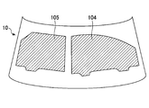
- a plurality of curved plates 104 and 105 may be cut out from one tempered glass plate 10.
- the plurality of curved plates 104 and 105 cut out from one tempered glass plate 10 are a plurality of window glasses on a design surface (for example, a side surface of a vehicle, a top surface of a vehicle, or a curved surface of a building) on which a plurality of window glasses are formed. It may be a shape corresponding to each.
- the plurality of curved plates 104 and 105 are a window glass attached to the front side of the left side surface of a certain type of vehicle and a window glass attached to the rear side of the left side surface of the same type of vehicle.
- the glass plate in the molding step of bending the glass plate, is bent so as to have at least the same curved surface as a continuous region where a plurality of window glasses on the design surface are formed.
- a glass plate is shape
- the plurality of curved plates are cut out from the positions of the tempered glass plates corresponding to the positions where the plurality of window glasses on the design surface are formed in the cutting step.
- each window glass is cut out from the position to be. Not only a plurality of window glasses but also a glass plate is formed on a design surface including a region other than a plurality of window glasses, and each window glass is cut out from the corresponding position. The surface looks beautiful.
- a plurality of curved plates 104 and 105 cut out from one tempered glass plate 10 is used as a plurality of window glasses that form the design surface of the same object.
- the plurality of curved plates 104 and 105 are a window glass attached to the front side of the left side surface of one vehicle and a window glass attached to the rear side of the left side surface of the same vehicle. Since a plurality of window glasses forming the same design surface are cut out from one tempered glass plate 10, the continuity of the plurality of window glasses is better and the appearance of the design surface is beautiful.
- the plurality of curved plates 104 and 105 cut out from one tempered glass plate 10 may be window glass attached to the same design surface of another object.
- the plurality of curved plates 104 and 105 are a window glass attached to the front side of the left side surface of one vehicle and a window glass attached to the rear side of the left side surface of another vehicle of the same shape.
- the continuity of the plurality of window glasses is better than when a single window glass is cut out from one tempered glass plate 10, and the appearance of the design surface is beautiful.
- the plurality of curved plates 104 and 105 cut out from one tempered glass plate 10 only need to be attached to different parts of the design surface, and may have different shapes or the same shape as shown in FIG.
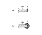
- FIG. 16 is a diagram showing a protection process according to the first embodiment.
- the method for manufacturing the curved plate may further include a step of protecting the cut surface of the cut curved plate (for example, the curved plate 101 in FIG. 16) with the resin 19. Instead of chamfering the cut surface of the curved plate, the curved plate is difficult to break.
- the resin 19 for example, a thermoplastic elastomer (for example, polyvinyl chloride) is used.
- the resin 19 may be formed only on the cut surface of the curved plate as shown in FIG. 16 (a), or may be formed so as to protrude from the cut surface of the curved plate as shown in FIG. 16 (b).
- FIG. 17 is an explanatory diagram of a cutting process according to the second embodiment.
- the same components as those in FIG. 17 are identical to FIG. 17 in FIG. 17, the same components as those in FIG. 17 in FIG. 17, the same components as those in FIG. 17
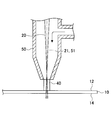
- the cutting step of the present embodiment includes a step of locally blowing the gas 40 to the tempered glass plate 10, and moving the spray position of the gas 40 on the tempered glass plate 10 in conjunction with the irradiation position of the laser light 20.
- the tempered glass plate 10 is cut.
- the irradiation position of the laser beam 20 may exist inside the spray position of the gas 40.
- the spray position of the gas 40 may be in front of or behind the irradiation position of the laser beam 20.
- the gas 40 blows off a deposit (for example, dust) on the tempered glass plate 10 to prevent the laser light 20 from being absorbed by the deposit and prevent the surface 12 of the tempered glass plate 10 from being overheated.
- the gas 40 may be a cooling gas that locally cools the tempered glass plate 10 (for example, compressed air at room temperature). Since a rapid temperature gradient occurs along the moving direction of the irradiation position of the laser beam 20, the distance between the position where the tensile stress reaches a predetermined value (that is, the tip position of the crack 30) and the position of the laser beam 20 is as follows. Shorter. Therefore, since the position controllability of the crack 30 is improved, the cutting accuracy can be further improved.
- a cooling gas that locally cools the tempered glass plate 10 (for example, compressed air at room temperature). Since a rapid temperature gradient occurs along the moving direction of the irradiation position of the laser beam 20, the distance between the position where the tensile stress reaches a predetermined value (that is, the tip position of the crack 30) and the position of the laser beam 20 is as follows. Shorter. Therefore, since the position controllability of the crack 30 is improved, the cutting accuracy can be further improved.
- the nozzle 50 is formed in a cylindrical shape as shown in FIG. 17, for example, and the laser beam 20 may pass through the nozzle 50.
- the central axis 51 of the nozzle 50 and the optical axis 21 of the laser light 20 may be arranged coaxially. The positional relationship between the spray position of the gas 40 and the irradiation position of the laser beam 20 is stabilized.
- the tempered glass plate 10 may move, the nozzle 50 may move, or both may move.
- the curved plate cut out from one tempered glass plate 10 may have a shape corresponding to the design surface of the object to be attached, and is attached to the same portion of each of the plurality of objects having the same design surface. It may be.
Landscapes
- Chemical & Material Sciences (AREA)
- Engineering & Computer Science (AREA)
- Materials Engineering (AREA)
- Organic Chemistry (AREA)
- Physics & Mathematics (AREA)
- Health & Medical Sciences (AREA)
- Optics & Photonics (AREA)
- Toxicology (AREA)
- Thermal Sciences (AREA)
- Re-Forming, After-Treatment, Cutting And Transporting Of Glass Products (AREA)
- Surface Treatment Of Glass (AREA)
- Laser Beam Processing (AREA)
Abstract
湾曲板の製造方法は、加熱により軟化したガラス板を曲げ成形する成形工程と、曲げ成形されたガラス板の表面及び裏面を強化し、強化ガラス板10を作製する強化工程と、強化ガラス板10に局所的にレーザ光を照射し、強化ガラス板10におけるレーザ光20の照射位置を移動させ、強化ガラス板10を板厚方向に貫通するクラック30を内部残留引張応力CTによって伸展させ、強化ガラス板10から湾曲板を切り出す切断工程とを有する。切断工程は、レーザ光20によって徐冷点以下の温度で中間層17を局所的に加熱し、内部残留引張応力CTよりも小さい引張応力、又は圧縮応力を中間層17に局所的に発生させ、内部残留引張応力によるクラック30の伸展速度を制御する。
Description
本発明は、湾曲板の製造方法に関する。
ガラスを強化する強化法として、例えば風冷強化法等の物理強化法、イオン交換法等の化学強化法がある。強化ガラス板は、ガラス板の表面や裏面に残留圧縮応力を生じさせ、ガラス板の表面や裏面を強化したものである。
従来、強化ガラス板の切断が困難であり、曲げ強化ガラス板である湾曲板の製造は、ガラス板を製品サイズに切断し、曲げ成形した後、強化することにより行われていた(例えば、特許文献1参照)。
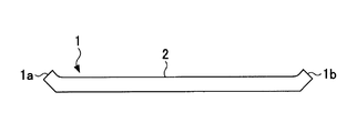
図1は、ガラス板の曲げ成形の説明図(1)である。図2は、図1のガラス板をA面で切断して示す断面図である。図1に示すように、加熱により軟化したガラス板1を曲げ成形するとき、ガラス板1の凸曲面2には、その曲線に沿って引張応力が生じ、引張応力及びポアソン比に応じた圧縮応力が曲線と垂直な方向に生じる。一方、ガラス板1の凹曲面3には、その曲線に沿って圧縮応力が生じ、圧縮応力及びポアソン比に応じた引張応力が曲線と垂直な方向に生じる。このように、凸曲面2と凹曲面3とには異なる応力場が形成され、図2に示すように、ガラス板1の両端1a、1bが意図しない方向に反るという問題があった。ガラス板1の両端1a、1bが反るのは、ガラス板1の端は自由端であるため、ガラス板1の内部よりも自由に動きやすいためである。
図3は、ガラス板の曲げ成形の説明図(2)である。図3では、加熱により軟化したガラス板1を複数の搬送ローラ4で搬送しながら、ガラス板1を曲げ成形する。複数の搬送ローラ4は、湾曲状の上り勾配の搬送経路を形成する。ガラス板1の前端1cや後端1dは自由端であるため、前端1cや後端1dには曲げ応力が生じにくく、前端1cや後端1dで曲げ不足が生じやすい。
図4は、ガラス板の曲げ成形の説明図(3)である。図4では、複数の搬送ロール4でガラス板1を搬送しながら、ガラス板1を曲げ成形するとき、ガラス板1の搬送経路が進行波となるように複数の搬送ロール4を上下動させる。この方法も、図3の方法と同様に、ガラス板1の前端1cや後端1dで曲げ不足が生じやすい。
図5は、ガラス板の曲げ成形の説明図(4)である。図5に示すように、ガラス板1の端部に貫通孔1eが形成されている場合、貫通孔1eの周辺部分1fでは、曲げ応力が生じにくく、曲げ不足が生じやすい。ガラス板1は例えば車両用窓ガラスであって、貫通孔1eは例えばワイパー孔である。
図6は、ガラス板の曲げ成形の説明図(5)である。図6に示すように、ガラス板1の外周の一部が凹んでいる場合、ガラス板1の凸部分1gでは、曲げ応力が生じにくく、曲げ不足が生じやすい。ガラス板1は例えば車両用窓ガラスである。
このように、ガラス板の曲げ成形では、意図しない反りや曲げ不足等の問題が生じやすく、求める形状のガラス板の製造が困難である。
従来、強化ガラス板の切断が困難であったため、曲げ強化ガラス板である湾曲板の製造は、ガラス板を製品サイズに切断し、曲げ成形した後、強化することにより行われていた。製品サイズのガラス板を曲げ成形すると、上述のように、反りや曲げ不足等の問題が生じ、求める形状の湾曲板を得ることが困難であった。
本発明は、上記課題に鑑みてなされたものであって、求める形状が得られる湾曲板の製造方法の提供を目的とする。
上記課題を解決するため、一の態様による湾曲板の製造方法は、
加熱により軟化したガラス板を曲げ成形する成形工程と、
曲げ成形されたガラス板の表面及び裏面を強化し、残留圧縮応力を有する強化層としての表面層及び裏面層、並びに該表面層と裏面層の間に形成され、内部残留引張応力を有する中間層を含む強化ガラス板を作製する強化工程と、
前記強化ガラス板におけるレーザ光の照射位置を移動させ、前記強化ガラス板を板厚方向に貫通するクラックを伸展させ、前記強化ガラス板から湾曲板を切り出す切断工程とを有し、
該切断工程は、前記レーザ光によって徐冷点以下の温度で前記中間層を局所的に加熱し、前記内部残留引張応力よりも小さい引張応力、又は圧縮応力を前記中間層に局所的に発生させ、前記内部残留引張応力によるクラックの伸展速度を制御する。
加熱により軟化したガラス板を曲げ成形する成形工程と、
曲げ成形されたガラス板の表面及び裏面を強化し、残留圧縮応力を有する強化層としての表面層及び裏面層、並びに該表面層と裏面層の間に形成され、内部残留引張応力を有する中間層を含む強化ガラス板を作製する強化工程と、
前記強化ガラス板におけるレーザ光の照射位置を移動させ、前記強化ガラス板を板厚方向に貫通するクラックを伸展させ、前記強化ガラス板から湾曲板を切り出す切断工程とを有し、
該切断工程は、前記レーザ光によって徐冷点以下の温度で前記中間層を局所的に加熱し、前記内部残留引張応力よりも小さい引張応力、又は圧縮応力を前記中間層に局所的に発生させ、前記内部残留引張応力によるクラックの伸展速度を制御する。
本発明によれば、求める形状が得られる湾曲板の製造方法が提供される。
以下、本発明を実施するための形態について図面を参照して説明する。各図面において、同一の又は対応する構成には、同一の又は対応する符号を付して説明を省略する。
[第1実施形態]
曲げ強化ガラス板である湾曲板の製造方法は、成形工程と、強化工程と、切断工程とをこの順で有する。
曲げ強化ガラス板である湾曲板の製造方法は、成形工程と、強化工程と、切断工程とをこの順で有する。
成形工程は、加熱により軟化したガラス板を曲げ成形する。曲げ成形方法は、多種多様であってよく、図3、図4に示すロール成形、リングでガラス板の外周部を支持し、ガラス板を自重で曲げる重力成形、ガラス板をモールドに押し付け、モールドに沿って曲げるプレス成形、ガラス板をモールドで真空吸着しモールドに沿って曲げる真空成形のいずれでもよい。これらの成形法は、組み合わせて用いることも可能である。例えば、プレス成形と真空成形との組み合わせ、プレス成形と重力成形との組合せ等が可能である。
強化工程は、曲げ成形したガラス板の表面や裏面に残留引張応力を生じさせ、ガラス板の表面や裏面を強化し、強化ガラス板を作製する。強化方法は、風冷強化法等の物理強化法、イオン交換法等の化学強化法のいずれでもよい。
風冷強化法は、軟化点付近の温度のガラス板を両側から急冷し、ガラス板の表面や裏面と、ガラス板の内部との間に温度差をつけることで、ガラス板の表面や裏面に残留圧縮応力を生じさせ、ガラス板の表面や裏面を強化する。
イオン交換法は、ガラス板の表面や裏面をイオン交換し、ガラスに含まれる小さなイオン半径のイオン(例えば、Liイオン、Naイオン)を大きなイオン半径のイオン(例えば、Kイオン)に置換する。これにより、ガラス板の表面や裏面に残留圧縮応力を生じさせ、ガラス板の表面や裏面を強化する。
ガラス板のガラスの種類は、特に限定されないが、例えばソーダライムガラス、無アルカリガラス等が挙げられる。ガラス板の厚さは、ガラス板の用途に応じて適宜設定され、例えば0.1~25mmである。物理強化による強化ガラス板の場合、1.5mm以上であると強化工程においてガラス板の表面や裏面と内部との間に温度差を付けやすくなるため好ましい。
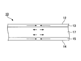
図7は、強化ガラス板の断面の一例を示す図である。図7において、矢印の方向は残留応力の作用方向を示し、矢印の大きさは応力の大きさを示す。
強化ガラス板10は、残留圧縮応力を有する強化層としての表面層13及び裏面層15、並びに表面層13と裏面層15との間に形成され、残留引張応力を有する中間層17を含む。
強化ガラス板10の端面は、表面層13の端部及び裏面層15の端部から延びる強化層で覆われていてよい。また、強化ガラス板10の端面は強化層で覆われておらず、強化ガラス板10の端面に中間層17の端面が露出していてもよい。
図8は、風冷強化ガラス板の残留応力分布の一例を示す模式図である。図9は、化学強化ガラス板の残留応力分布の一例を示す模式図である。
図8及び図9に示すように、強化ガラス板10の板厚方向両端から内部に向かうほど残留圧縮応力が小さくなり、強化ガラス板10の内部には残留引張応力が生じている。
図8及び図9において、CSは強化層13、15の最大残留圧縮応力(表面圧縮応力)(>0)、CTは中間層17における内部残留引張応力(>0)、DOLは強化層13、15の厚さをそれぞれ示す。CSやCT、DOLは、強化処理条件(風冷強化法の場合にはガラス板の加熱温度や冷却速度等、イオン交換法の場合には処理液の濃度や温度、処理液へのガラス板の浸漬時間等)で調節可能である。
強化層13、15の表面圧縮応力(CS)及び強化層13、15の厚さ(DOL)は、例えば、表面応力計FSM-6000(折原製作所製)により測定される。
化学強化ガラス板の場合、中間層17の内部残留引張応力(CT)は、下記の数式(1)で算出される。
CT=(CS×DOL)/(t-2×DOL)・・・(1)
尚、表面層13及び裏面層15が異なる厚さ、異なる最大圧縮応力を有している場合、内部残留引張応力(CT)は、下記の数式(2)で算出される。
CT=(C1×D1/2+C2×D2/2)/(t-D1-D2)・・・(2)
上記式(2)中、C1は表面層13の最大残留圧縮応力、D1は表面層13の厚さ、C2は裏面層15の最大残留圧縮応力、D2は裏面層15の厚さを示す。
CT=(CS×DOL)/(t-2×DOL)・・・(1)
尚、表面層13及び裏面層15が異なる厚さ、異なる最大圧縮応力を有している場合、内部残留引張応力(CT)は、下記の数式(2)で算出される。
CT=(C1×D1/2+C2×D2/2)/(t-D1-D2)・・・(2)
上記式(2)中、C1は表面層13の最大残留圧縮応力、D1は表面層13の厚さ、C2は裏面層15の最大残留圧縮応力、D2は裏面層15の厚さを示す。
物理強化ガラス板の場合、中間層17の内部残留引張応力(CT)は、下記の数式(3)で算出される。
CT=CS/a (3)
数式(3)において、aはガラス板の冷却開始時の温度、ガラスの冷却速度、ガラス板の厚さなどで決まる定数であって、通常は2.0~2.5の範囲内である。
CT=CS/a (3)
数式(3)において、aはガラス板の冷却開始時の温度、ガラスの冷却速度、ガラス板の厚さなどで決まる定数であって、通常は2.0~2.5の範囲内である。
図10は、第1実施形態による切断工程の説明図である。図11は、強化ガラス板におけるレーザ光の照射位置と、クラックの先端位置との関係の一例を示す図である。
切断工程では、強化ガラス板10から湾曲板を切り出す。湾曲板は少なくとも一部が湾曲していればよく、一部が平坦であってもよい
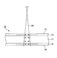
切断工程では、強化ガラス板10に局所的にレーザ光20を照射し、強化ガラス板10におけるレーザ光20の照射位置を移動させ、強化ガラス板10を板厚方向に貫通するクラック30を伸展させる。強化ガラス板10におけるレーザ光20の照射位置の軌跡に沿って、クラック30が伸展する。強化ガラス板10におけるレーザ光20の照射位置の移動のため、強化ガラス板10が移動してもよいし、レーザ光20の光源が移動してもよく、両者が移動してもよい。強化ガラス板10の移動の代わりに、強化ガラス板10の回転を行ってもよい。また、強化ガラス板10におけるレーザ光20の照射位置の移動のため、光源からのレーザ光を強化ガラス板10に向けて反射するガルバノミラーを回転してもよい。
切断工程では、強化ガラス板10に局所的にレーザ光20を照射し、強化ガラス板10におけるレーザ光20の照射位置を移動させ、強化ガラス板10を板厚方向に貫通するクラック30を伸展させる。強化ガラス板10におけるレーザ光20の照射位置の軌跡に沿って、クラック30が伸展する。強化ガラス板10におけるレーザ光20の照射位置の移動のため、強化ガラス板10が移動してもよいし、レーザ光20の光源が移動してもよく、両者が移動してもよい。強化ガラス板10の移動の代わりに、強化ガラス板10の回転を行ってもよい。また、強化ガラス板10におけるレーザ光20の照射位置の移動のため、光源からのレーザ光を強化ガラス板10に向けて反射するガルバノミラーを回転してもよい。
クラック30は強化ガラス板10を板厚方向に貫通しており、本実施形態の切断は所謂フルカット切断である。
強化ガラス板10の切断位置には、レーザ照射前に、スクライブ線(溝線)が形成されなくてよい。スクライブ線が形成されてもよいが、スクライブ線の形成に手間がかかる。また、スクライブ線の形成時に、強化ガラス板10が欠けることがある。
強化ガラス板10の切断開始位置には、初期クラックが形成されてよい。初期クラックは、例えばカッタやヤスリ、レーザで形成される。強化ガラス板10の端面が砥石等で研削されたものである場合、研削によって形成されるマイクロクラックを初期クラックとして利用できる。
強化ガラス板10の切断開始位置や切断終了位置は、強化ガラス板10の外周、強化ガラス板10の内部のいずれでもよい。また、強化ガラス板10の切断線の形状は、多種多様であってよい。
レーザ光20は、光源から出射された後、集光レンズ等の光学系で集光され、強化ガラス板10の表面12に入射し、強化ガラス板10の裏面14から出射する。
強化ガラス板10の表面12におけるレーザ光20の強度をI0とし、強化ガラス板10中を距離L(cm)だけ移動したときのレーザ光20の強度をIとすると、I=I0×exp(-α×L)の式が成立する。この式は、ランベルト・ベールの法則と呼ばれるものである。αはレーザ光20に対する強化ガラス板10の吸収係数(cm-1)を表し、レーザ光20の波長や強化ガラス板10の化学組成等で決まる。αは紫外可視近赤外分光光度計等により測定される。
レーザ光20が強化ガラス板10を通過する間に、強化ガラス板10がレーザ光20の照射エネルギーの一部を熱として吸収し、強化ガラス板10に熱応力が生じる。この熱応力を利用して、強化ガラス板10の切断を制御する。
ところで、本実施形態の強化ガラス板10の切断と、非強化ガラスの切断とは、切断のメカニズムが根本的に異なり、クラックの伸展の仕方が全く異なる。
非強化ガラス板の切断では、ガラス板をレーザ光で局所的に加熱すると共に、ガラス板におけるレーザ光の照射位置を移動させ、移動方向に沿って温度勾配を形成する。レーザ光の照射位置の後方近傍に引張応力が生じ、この引張応力でクラックが伸展する。クラックの先端位置は、レーザ光の照射位置の移動に伴い、レーザ光の照射位置に追従する。このように、クラックの伸展は、レーザ光の照射エネルギーのみで行われる。従って、切断の途中でレーザ照射を中断すると、クラックの伸展が止まる。
これに対し、本実施形態の強化ガラスの切断では、元々ガラス板内部に存在する残留引張応力を利用するために、非強化ガラスの切断の場合のように、レーザ光で引張応力を発生させなくてもよい。また、強化ガラス板に何らかの力を作用させてクラックを発生させると、残留引張応力のためにクラックは自ら伸展する。また、ガラス板内部の残留引張応力はガラス板全体に存在しているのでクラックは任意の方向に伸展しうる。さらにクラックの伸展速度がある速度まで達するとクラックが分岐する。
本発明者の知見によると、中間層17の内部残留引張応力(CT)が30MPa以上になると、中間層17の残留引張応力のみで、強化ガラス板10に形成されたクラックが自然に伸展する(自走する)。
そこで、本実施形態では、内部残留引張応力CTによるクラック30を伸展させることで強化ガラス板10を切断しつつ、レーザ光20によって徐冷点以下の温度で中間層17を局所的に加熱し、内部残留引張応力CTよりも小さい引張応力、又は圧縮応力を中間層17に局所的に発生させ、内部残留引張応力CTによるクラック30の伸展を抑制する。すなわち、レーザ光20の照射位置の移動速度を制御することで、クラック30の伸展速度を制御することができる。クラック30の伸展速度を制御することにより、クラック30の伸展する方向を定めることができ、また、クラック30の分岐を防止できる。つまり、クラックの伸展速度を制御することにより、クラック30の伸展の軌跡を高い精度で制御できる。尚、中間層17を徐冷点以下の温度で加熱するのは、徐冷点を超えて加熱すると、ガラス板の粘性流動により熱応力が緩和されるからである。
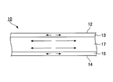
図12は、図11のA-A線に沿った断面での応力分布の一例を示す模式図である。図13は、図11のB-B線に沿った断面での応力分布の一例を示す模式図である。図13の断面は、図12の断面よりも後方の断面である。ここで、「後方」とは、強化ガラス板におけるレーザ光の照射位置の移動方向後方(即ち、強化ガラス板におけるクラックの伸展方向後方)を意味する。図12及び図13において、矢印の方向は応力の作用方向を示し、矢印の長さは応力の大きさを示す。
図12に示すように、中間層17のレーザ照射部分は加熱され、中間層17の他の部分よりも高温になる。そのため、中間層17のレーザ照射部分では、内部残留引張応力CTよりも小さい引張応力、又は圧縮応力が生じ、内部残留引張応力CTによるクラック30の伸展が抑制される。図12に示すように圧縮応力が生じていると、クラック30の伸展を確実に防止できる。一方、内部残留引張応力CTよりも小さい引張応力が生じていると、クラック30の先端位置と、レーザ光20の照射位置とが近くなり、クラック30の先端位置を精度良く制御できる。
これに対し、図13に示すように、中間層17のレーザ照射部分の後方近傍は、中間層17のレーザ照射部分よりも低温になる。そのため、中間層17のレーザ照射部分の後方近傍に、内部残留引張応力CTよりも大きい引張応力が生じる。クラック30は引張応力が所定値を超える部分に形成され、引張応力の大きい部分に集中する。そのため、クラック30の先端位置は、レーザ光20の照射位置の軌跡から外れることはない。
クラック30の先端位置は、レーザ光20の照射位置の移動に伴い、レーザ光20の照射位置に追従し、レーザ光20の照射位置を追い越さない。クラック30の先端位置は、レーザ光20の照射位置を追い越さない限り、レーザ光20の照射位置と一部重なっていてもよい。
このように、本実施形態によれば、レーザ光20によって中間層17を局所的に加熱し、内部残留引張応力CTよりも小さい引張応力、又は圧縮応力を中間層17に局所的に発生させ、内部残留引張応力CTによるクラック30の伸展を抑制する。従って、クラック30の先端位置を精度良く制御することができ、切断精度を向上することができる。
尚、図12に示すように、強化層13、15のレーザ照射部分は、加熱され、強化層13、15の他の部分よりも高温になる。そのため、強化層13、15のレーザ照射部分では、図7~図9に示す残留圧縮応力よりも大きい圧縮応力が生じ、クラック30の伸展が抑制される。
本実施形態では、強化層13、15だけでなく、中間層17をレーザ光20で加熱するため、内部透過率の高いレーザ光20を使用する。強化ガラス板10に入射してから出射するまでのレーザ光20の移動距離をMとすると、α×Mが3.0以下である(即ち、レーザ光の内部透過率が5%以上である)ことが好ましい。
α×Mを3.0以下とすることにより、レーザ光20の照射エネルギーの大部分が強化ガラス板10の表面12近傍で熱として吸収されてしまうのを防ぎ、板厚方向に急激な温度勾配が生じるのを良好に防ぐことができる。これにより、表面層13のレーザ照射部分が中間層17のレーザ照射部分よりも著しく高温になるのを防ぎ、中間層17のレーザ照射部分に内部残留引張応力CTよりも大きな引張応力が生じるのを防ぐことができる。そのため、クラック30の先端位置がレーザ光20の照射位置を追い越すのを防ぐことができる。
α×Mは、より好ましくは0.3以下(レーザ光の内部透過率74%以上)、さらに好ましくは0.105以下(レーザ光の内部透過率90%以上)、特に好ましくは0.02以下(レーザ光の内部透過率98%以上)である。
レーザ光20が強化ガラス板10の表面12に垂直に入射する場合、レーザ光20の移動距離Mは、強化ガラス板10の板厚tと同じ値(M=t)となる。一方、レーザ光20は強化ガラス板10の表面12に斜めに入射する場合、スネルの法則に従って屈折する。屈折角をγとすると、レーザ光20の移動距離Mは、M=t/cosγの式で近似的に求められる。
クラック30の伸展は主に中間層17の残留引張応力で行われるように、内部残留引張応力CTは15MPa以上であることが好ましい。これにより、引張応力が所定値に達する位置(即ち、クラック30の先端位置)と、レーザ光20の照射位置とが十分に近くなり、切断精度が向上する。内部残留引張応力CTは、より好ましくは30MPa以上、さらに好ましくは40MPaである。内部残留引張応力CTが30MPa以上であると、中間層17の残留引張応力のみでクラック30が伸展し、クラック30の先端位置と、レーザ光20の照射位置とがさらに近くなるので、切断精度がさらに向上する。
レーザ光20の光源としては、例えば波長が800~1100nmの近赤外線(以下、単に「近赤外線」という)のレーザが用いられる。近赤外線レーザとしては、例えば、Ybファイバーレーザ(波長:1000~1100nm)、Ybディスクレーザ(波長:1000~1100nm)、Nd:YAGレーザ(波長:1064nm)、高出力半導体レーザ(波長:808~980nm)が挙げられる。これらの近赤外線レーザは、高出力で安価であり、また、α×Mを所望の範囲に調整するのが容易である。
尚、本実施形態では、レーザ光20の光源として高出力で安価な近赤外線レーザが用いられるが、波長が250~5000nmの光源であればよい。例えば、UVレーザ(波長:355nm)、グリーンレーザ(波長:532nm)、Ho:YAGレーザ(波長:2080nm)、Er:YAGレーザ(2940nm)、中赤外光パラメトリック発振器を使用したレーザ(波長:2600~3450nm)等が挙げられる。また、レーザ光20の発振方式に制限はなく、レーザ光を連続発振するCWレーザ、レーザ光を断続発振するパルスレーザのいずれも使用可能である。また、レーザ光20の強度分布に制限はなく、ガウシアン型であっても、トップハット型であってもよい。
1000nm付近(800~1100nm)の近赤外線レーザの場合、強化ガラス板10中の鉄(Fe)の含有量、コバルト(Co)の含有量、銅(Cu)の含有量が多くなるほど、吸収係数αが大きくなる。また、この場合、強化ガラス板10中の希土類元素(例えばYb)の含有量が多くなるほど、希土類原子の吸収波長付近で吸収係数αが大きくなる。吸収係数αの調節にはガラスの透明性、及びコストの観点から鉄が用いられ、コバルト、銅、及び希土類元素は強化ガラス板10中に実質的に含まれていなくてよい。
レーザ光20の強度は、ランベルト・ベールの法則に従って減衰する。そこで、強化ガラス板10の表面12と裏面14とで、レーザパワー密度(W/cm2)が同じか略同じになるように、つまり、温度が同じか略同じになるように、裏面14におけるレーザ光20の面積は、表面12におけるレーザ光20の面積よりも小さくてよい。強化ガラス板10を基準として光源と反対側にレーザ光20の集光位置があると、裏面14におけるレーザ光20の面積が、表面12におけるレーザ光20の面積よりも小さくなる。強化ガラス板10の表面12と裏面14とで温度が同程度であると、強化ガラス板10の表面12と裏面14とでクラック30が同程度に伸展する。
尚、レーザ光20の集光位置は、強化ガラス板10の内部でもよく、また、図12に示すように強化ガラス板10を基準として光源側であってもよい。
強化ガラス板10の表面12において、レーザ光20は強化ガラス板10の板厚tよりも小さい直径φの円形に形成されてよい。直径φを板厚tよりも小さくすることにより、ガラス板10の加熱部分が大きくなり過ぎず、切断面の一部(特に切断開始部分や切断終了部分)が僅かに湾曲するのを防ぐことができる。
尚、強化ガラス板10の表面12におけるレーザ光20の形状は、多種多様であってよく、例えば矩形、楕円形等でもよい。
切断工程で強化ガラス板10から切り出される湾曲板の用途としては、例えば、車両用窓ガラス、建築用窓ガラス、太陽熱発電(Concentrated Solar thermal Power)用曲面鏡、携帯電話やノートパソコン等の携帯機器の筐体等が挙げられる。
図14は、強化ガラス板から切り出される湾曲板の切り出し位置の一例を示す図である。図14において、強化ガラス板から切り出される湾曲板の部分を斜線で示す。
切断工程では、強化ガラス板10のうち、意図しない反り、曲げ不足等の不具合のない部分から、湾曲板101、102、103を切り出すことができる。よって、求める形状の湾曲板を得ることができる。
例えば、図14(a)では、意図しない反り、曲げ不足等の不具合のある部分として、強化ガラス板10の端部を切除することにより、求める形状の湾曲板101を得る。
また、図14(b)では、不具合のある部分として、強化ガラス板10の外周部を切除することにより、求める形状の湾曲板102を得る。風冷強化の場合、強化ガラス板10の外周部をリングで支持するので、強化ガラス板10の支持跡がついた部分を不具合のある部分として切除することもできる。
さらに、図14(c)では、図6に示すように切断後に曲げ成形すると曲げ不足となる形状の湾曲板を、曲げ成形後に切断することで所望の形状にすることができる。この場合、強化ガラス板10には不具合がなくてもよい。また、同様に図5のような貫通孔を有する形状であっても所望の形状にすることができる。
図15は、強化ガラス板から切り出される湾曲板の切り出し位置の別の一例を示す図である。図15において、強化ガラス板から切り出される湾曲板の部分を斜線で示す。
切断工程では、1つの強化ガラス板10から複数の湾曲板104、105を切り出してよい。1つの強化ガラス板10から切り出される複数の湾曲板104、105は、複数の窓ガラスが形成される意匠面(例えば、車両の側面や車両の上面、建築物の湾曲面)の複数の窓ガラスにそれぞれ対応した形状であってよい。例えば、複数の湾曲板104、105は、ある型式の車両の左側面の前側に取り付けられる窓ガラス、同一の型式の車両の左側面の後側に取り付けられる窓ガラスである。その場合、ガラス板を曲げ成形する成形工程は、少なくとも意匠面の複数の窓ガラスが形成される連続した領域と同じ湾曲面となるようにガラス板を曲げ成形する。例えば、車両の側面であれば、前側の窓ガラスと後側の窓ガラスと各窓ガラス間の領域を含めた連続した領域の湾曲面と同じ湾曲面となるようにガラス板を成形する。そして、強化工程を経て、切断工程にて、意匠面の複数の窓ガラスが形成される位置に対応する強化ガラス板の位置からそれぞれ複数の湾曲板を切り出す。例えば、車両の側面であれば、車両側面と同じ湾曲面に成形されている強化ガラス板10から、実際に前側の窓ガラスが形成される位置と後側の窓ガラスが形成される位置に対応する位置から各窓ガラスを切り出す。複数の窓ガラスだけでなく複数の窓ガラス以外の領域を含む意匠面にガラス板を成形した上で、対応する位置から各窓ガラスが切り出されるので、複数の窓ガラスの連続性が良く、意匠面の見た目が美しい。
さらに、1つの強化ガラス板10から切り出される複数の湾曲板104、105が、同一の物体の意匠面を形成する複数の窓ガラスとして用いられることが好ましい。例えば、複数の湾曲板104、105は、一の車両の左側面の前側に取り付けられる窓ガラス、同一の車両の左側面の後側に取り付けられる窓ガラスである。一枚の強化ガラス板10から、同一の意匠面を形成する複数の窓ガラスが切り出されるので、より複数の窓ガラスの連続性が良く、意匠面の見た目が美しい。
なお、1つの強化ガラス板10から切り出される複数の湾曲板104、105は、それぞれ別の物体の同形の意匠面に取り付けられる窓ガラスであってもよい。例えば、複数の湾曲板104、105は、一の車両の左側面の前側に取り付けられる窓ガラス、同形の別の車両の左側面の後側に取り付けられる窓ガラスである。一枚の強化ガラス板10から一枚の窓ガラスを切り出す場合よりも、複数の窓ガラスの連続性が良く、意匠面の見た目が美しい。
尚、1つの強化ガラス板10から切り出される複数の湾曲板104、105は、意匠面の異なる部位に取付けられるものであればよく、図15に示すように異なる形状でも、同じ形状でもよい。
図16は、第1実施形態による保護工程を示す図である。
湾曲板の製造方法は、切り出した湾曲板(例えば図16では湾曲板101)の切断面を樹脂19で保護する工程をさらに有してよい。湾曲板の切断面の面取りの代わりになり、湾曲板が割れにくくなる。樹脂19としては、例えば熱可塑性エラストマー(例えばポリ塩化ビニル)が用いられる。
樹脂19は、図16(a)に示すように湾曲板の切断面のみに形成されてもよいし、図16(b)に示すように湾曲板の切断面からはみ出して形成されてもよい。
[第2実施形態]
図17は、第2実施形態による切断工程の説明図である。図17において、図10と同一の構成には同一の符号を付して説明を省略する。
図17は、第2実施形態による切断工程の説明図である。図17において、図10と同一の構成には同一の符号を付して説明を省略する。
本実施形態の切断工程は、強化ガラス板10に局所的にガス40を吹き付ける工程を含み、強化ガラス板10におけるガス40の吹き付け位置を、レーザ光20の照射位置と連動して移動させることで、強化ガラス板10を切断する。図17に示すように、ガス40の吹き付け位置の内側に、レーザ光20の照射位置が存在してよい。尚、ガス40の吹き付け位置は、レーザ光20の照射位置よりも前方又は後方でもよい。ガス40は、強化ガラス板10の付着物(例えばホコリ)を吹き飛ばして、付着物によるレーザ光20の吸収を防止し、強化ガラス板10の表面12の過熱を防止する。
ガス40は、強化ガラス板10を局所的に冷却する冷却ガス(例えば、室温の圧縮空気)であってもよい。レーザ光20の照射位置の移動方向に沿って急激な温度勾配が生じるので、引張応力が所定値に達する位置(即ち、クラック30の先端位置)と、レーザ光20の位置との間の距離が短くなる。よって、クラック30の位置制御性が高まるため、切断精度をさらに向上できる。
ノズル50は、例えば図17に示すように筒状に形成され、ノズル50の内部をレーザ光20が通過してよい。ノズル50の中心軸51と、レーザ光20の光軸21とは同軸的に配置されてよい。ガス40の吹き付け位置と、レーザ光20の照射位置との位置関係が安定化する。
強化ガラス板10におけるガス40の吹き付け位置の移動のため、強化ガラス板10が移動してもよいし、ノズル50が移動してもよく、両者が移動してもよい。
以上、湾曲板の切断方法の第1~第2実施形態を説明したが、本発明は上記実施形態に限定されず、特許請求の範囲に記載された範囲で、種々の変形及び置換が可能である。
例えば、1つの強化ガラス板10から切り出される湾曲板は、取付け対象の物体の意匠面に対応する形状となっていればよく、同形の意匠面を有する複数の物体それぞれの同じ部位に取り付けられるものであってもよい。
本国際出願は2012年7月11日に出願された日本国特許出願2012-155895号に基づく優先権を主張するものであり、その全内容をここに援用する。
10 強化ガラス板
12 表面
13 表面層
14 裏面
15 裏面層
17 中間層
20 レーザ光
30 クラック
40 ガス
12 表面
13 表面層
14 裏面
15 裏面層
17 中間層
20 レーザ光
30 クラック
40 ガス
Claims (10)
- 加熱により軟化したガラス板を曲げ成形する成形工程と、
曲げ成形されたガラス板の表面及び裏面を強化し、残留圧縮応力を有する強化層としての表面層及び裏面層、並びに該表面層と裏面層の間に形成され、内部残留引張応力を有する中間層を含む強化ガラス板を作製する強化工程と、
前記強化ガラス板に局所的にレーザ光を照射し、前記強化ガラス板におけるレーザ光の照射位置を移動させ、前記強化ガラス板を板厚方向に貫通するクラックを伸展させ、前記強化ガラス板から湾曲板を切り出す切断工程とを有し、
該切断工程は、前記レーザ光によって徐冷点以下の温度で前記中間層を局所的に加熱し、前記内部残留引張応力よりも小さい引張応力、又は圧縮応力を前記中間層に局所的に発生させ、前記内部残留引張応力によるクラックの伸展速度を制御する、湾曲板の製造方法。 - 前記切断工程は、1つの前記強化ガラス板から、複数の湾曲板を切り出す、請求項1に記載の湾曲板の製造方法。
- 1つの前記強化ガラス板から切り出される前記複数の湾曲板は、複数の窓ガラスが形成される意匠面の該複数の窓ガラスにそれぞれ対応した形状であり、
前記成形工程は、少なくとも前記意匠面の複数の窓ガラスが形成される連続した領域と同じ湾曲面となるように前記ガラス板を曲げ成形し、
前記切断工程は、前記意匠面の複数の窓ガラスが形成される位置に対応する前記強化ガラス板の位置からそれぞれ前記複数の湾曲板を切り出す、請求項2に記載の曲げ強化ガラス板の製造方法。 - 前記複数の湾曲板は、同一の物体の前記意匠面を形成する複数の窓ガラスである、請求項2に記載の湾曲板の製造方法。
- 前記湾曲板の切断面を樹脂で保護する保護工程をさらに有する、請求項1~4のいずれか一項に記載の湾曲板の製造方法。
- 前記レーザ光の波長が250~5000nmである、請求項1~5のいずれか一項に記載の湾曲板の製造方法。
- 前記中間層の内部残留引張応力が15MPa以上である、請求項1~6のいずれか一項に記載の湾曲板の製造方法。
- 前記中間層の内部残留引張応力が30MPa以上である、請求項7に記載の湾曲板の製造方法。
- 前記切断工程は、前記強化ガラス板に局所的にガスを吹き付ける工程を含み、前記強化ガラス板におけるガスの吹き付け位置を、前記レーザ光の照射位置と連動して移動させる、請求項1~8のいずれか一項に記載の湾曲板の製造方法。
- 前記ガスは、前記レーザ光で加熱される前記強化ガラス板を冷却する冷却ガスである、請求項9に記載の湾曲板の製造方法。
Applications Claiming Priority (2)
| Application Number | Priority Date | Filing Date | Title |
|---|---|---|---|
| JP2012155895A JP2015171955A (ja) | 2012-07-11 | 2012-07-11 | 湾曲板の製造方法 |
| JP2012-155895 | 2012-07-11 |
Publications (1)
| Publication Number | Publication Date |
|---|---|
| WO2014010600A1 true WO2014010600A1 (ja) | 2014-01-16 |
Family
ID=49916052
Family Applications (1)
| Application Number | Title | Priority Date | Filing Date |
|---|---|---|---|
| PCT/JP2013/068776 Ceased WO2014010600A1 (ja) | 2012-07-11 | 2013-07-09 | 湾曲板の製造方法 |
Country Status (3)
| Country | Link |
|---|---|
| JP (1) | JP2015171955A (ja) |
| TW (1) | TW201412663A (ja) |
| WO (1) | WO2014010600A1 (ja) |
Cited By (3)
| Publication number | Priority date | Publication date | Assignee | Title |
|---|---|---|---|---|
| WO2021157305A1 (ja) * | 2020-02-05 | 2021-08-12 | 日本電気硝子株式会社 | ガラス板の製造方法 |
| US20210300811A1 (en) * | 2018-06-30 | 2021-09-30 | Agp America S.A. | Method for manufacturing flush vehicle glazing |
| WO2025106200A1 (en) * | 2023-11-15 | 2025-05-22 | Corning Incorporated | Reformed glass-based articles and method of making the same |
Families Citing this family (2)
| Publication number | Priority date | Publication date | Assignee | Title |
|---|---|---|---|---|
| EP3505988B1 (en) * | 2016-08-24 | 2021-05-19 | Hamamatsu Photonics K.K. | Fabry-perot interference filter |
| JP6775822B2 (ja) * | 2016-09-28 | 2020-10-28 | 三星ダイヤモンド工業株式会社 | 脆性材料基板の分断方法並びに分断装置 |
Citations (7)
| Publication number | Priority date | Publication date | Assignee | Title |
|---|---|---|---|---|
| JP2006256944A (ja) * | 2005-03-14 | 2006-09-28 | Lemi Ltd | 脆性材料の割断方法及び装置 |
| WO2010135614A1 (en) * | 2009-05-21 | 2010-11-25 | Corning Incorporated | Thin substrates having mechanically durable edges |
| WO2011025903A1 (en) * | 2009-08-28 | 2011-03-03 | Corning Incorporated | Methods for laser cutting glass substrates |
| WO2011142464A1 (ja) * | 2010-05-14 | 2011-11-17 | 旭硝子株式会社 | 切断方法および切断装置 |
| WO2012096285A1 (ja) * | 2011-01-11 | 2012-07-19 | 旭硝子株式会社 | 強化ガラス板の切断方法 |
| WO2013031778A1 (ja) * | 2011-08-31 | 2013-03-07 | 旭硝子株式会社 | 強化ガラス板の切断方法、および強化ガラス板切断装置 |
| JP2013119495A (ja) * | 2011-12-07 | 2013-06-17 | Asahi Glass Co Ltd | 強化ガラス板の切断方法 |
-
2012
- 2012-07-11 JP JP2012155895A patent/JP2015171955A/ja active Pending
-
2013
- 2013-07-09 WO PCT/JP2013/068776 patent/WO2014010600A1/ja not_active Ceased
- 2013-07-11 TW TW102124981A patent/TW201412663A/zh unknown
Patent Citations (7)
| Publication number | Priority date | Publication date | Assignee | Title |
|---|---|---|---|---|
| JP2006256944A (ja) * | 2005-03-14 | 2006-09-28 | Lemi Ltd | 脆性材料の割断方法及び装置 |
| WO2010135614A1 (en) * | 2009-05-21 | 2010-11-25 | Corning Incorporated | Thin substrates having mechanically durable edges |
| WO2011025903A1 (en) * | 2009-08-28 | 2011-03-03 | Corning Incorporated | Methods for laser cutting glass substrates |
| WO2011142464A1 (ja) * | 2010-05-14 | 2011-11-17 | 旭硝子株式会社 | 切断方法および切断装置 |
| WO2012096285A1 (ja) * | 2011-01-11 | 2012-07-19 | 旭硝子株式会社 | 強化ガラス板の切断方法 |
| WO2013031778A1 (ja) * | 2011-08-31 | 2013-03-07 | 旭硝子株式会社 | 強化ガラス板の切断方法、および強化ガラス板切断装置 |
| JP2013119495A (ja) * | 2011-12-07 | 2013-06-17 | Asahi Glass Co Ltd | 強化ガラス板の切断方法 |
Cited By (6)
| Publication number | Priority date | Publication date | Assignee | Title |
|---|---|---|---|---|
| US20210300811A1 (en) * | 2018-06-30 | 2021-09-30 | Agp America S.A. | Method for manufacturing flush vehicle glazing |
| US11718551B2 (en) * | 2018-06-30 | 2023-08-08 | Agp America S.A. | Method for manufacturing flush vehicle glazing |
| WO2021157305A1 (ja) * | 2020-02-05 | 2021-08-12 | 日本電気硝子株式会社 | ガラス板の製造方法 |
| JP2021123518A (ja) * | 2020-02-05 | 2021-08-30 | 日本電気硝子株式会社 | ガラス板の製造方法 |
| JP7515777B2 (ja) | 2020-02-05 | 2024-07-16 | 日本電気硝子株式会社 | ガラス板の製造方法 |
| WO2025106200A1 (en) * | 2023-11-15 | 2025-05-22 | Corning Incorporated | Reformed glass-based articles and method of making the same |
Also Published As
| Publication number | Publication date |
|---|---|
| TW201412663A (zh) | 2014-04-01 |
| JP2015171955A (ja) | 2015-10-01 |
Similar Documents
| Publication | Publication Date | Title |
|---|---|---|
| JP5201295B2 (ja) | 強化ガラス板の切断方法 | |
| WO2014010599A1 (ja) | 積層板の製造方法 | |
| CN103781734A (zh) | 强化玻璃板的切断方法及强化玻璃板切断装置 | |
| JPWO2014010689A1 (ja) | 小サイズ板の製造方法及び構造体並びに構造体の製造方法 | |
| WO2012172960A1 (ja) | ガラス板の切断方法 | |
| WO2013031778A1 (ja) | 強化ガラス板の切断方法、および強化ガラス板切断装置 | |
| TWI637922B (zh) | 玻璃基板之倒角方法及雷射加工裝置 | |
| JP2013203630A (ja) | 強化ガラス板の切断方法 | |
| US9334188B2 (en) | Method for processing glass plate | |
| JP2015171955A (ja) | 湾曲板の製造方法 | |
| WO2014175147A1 (ja) | ガラス板の切断方法 | |
| TW201309608A (zh) | 板玻璃、其製造方法、及其製造裝置 | |
| WO2014010686A1 (ja) | 機能性基板の製造方法 | |
| JP6725836B2 (ja) | 切断ガラス板の製造方法及びガラス素板の切断装置 | |
| WO2014171396A1 (ja) | ガラス板の切断方法 | |
| WO2014175146A1 (ja) | ガラス板の切断方法 | |
| WO2014175145A1 (ja) | ガラス板の切断方法 | |
| JP2015034095A (ja) | 強化ガラス板の切断方法、および強化ガラス板切断装置 |
Legal Events
| Date | Code | Title | Description |
|---|---|---|---|
| 121 | Ep: the epo has been informed by wipo that ep was designated in this application |
Ref document number: 13816159 Country of ref document: EP Kind code of ref document: A1 |
|
| NENP | Non-entry into the national phase |
Ref country code: DE |
|
| 122 | Ep: pct application non-entry in european phase |
Ref document number: 13816159 Country of ref document: EP Kind code of ref document: A1 |
|
| NENP | Non-entry into the national phase |
Ref country code: JP |