WO2014010366A1 - 拡管用プラグ - Google Patents
拡管用プラグ Download PDFInfo
- Publication number
- WO2014010366A1 WO2014010366A1 PCT/JP2013/066458 JP2013066458W WO2014010366A1 WO 2014010366 A1 WO2014010366 A1 WO 2014010366A1 JP 2013066458 W JP2013066458 W JP 2013066458W WO 2014010366 A1 WO2014010366 A1 WO 2014010366A1
- Authority
- WO
- WIPO (PCT)
- Prior art keywords
- tube
- pipe
- expansion
- aluminum
- lubricating oil
- Prior art date
- Legal status (The legal status is an assumption and is not a legal conclusion. Google has not performed a legal analysis and makes no representation as to the accuracy of the status listed.)
- Ceased
Links
Images

Classifications
-
- B—PERFORMING OPERATIONS; TRANSPORTING
- B21—MECHANICAL METAL-WORKING WITHOUT ESSENTIALLY REMOVING MATERIAL; PUNCHING METAL
- B21D—WORKING OR PROCESSING OF SHEET METAL OR METAL TUBES, RODS OR PROFILES WITHOUT ESSENTIALLY REMOVING MATERIAL; PUNCHING METAL
- B21D37/00—Tools as parts of machines covered by this subclass
- B21D37/18—Lubricating, e.g. lubricating tool and workpiece simultaneously
-
- B—PERFORMING OPERATIONS; TRANSPORTING
- B21—MECHANICAL METAL-WORKING WITHOUT ESSENTIALLY REMOVING MATERIAL; PUNCHING METAL
- B21D—WORKING OR PROCESSING OF SHEET METAL OR METAL TUBES, RODS OR PROFILES WITHOUT ESSENTIALLY REMOVING MATERIAL; PUNCHING METAL
- B21D39/00—Application of procedures in order to connect objects or parts, e.g. coating with sheet metal otherwise than by plating; Tube expanders
- B21D39/08—Tube expanders
- B21D39/20—Tube expanders with mandrels, e.g. expandable
-
- B—PERFORMING OPERATIONS; TRANSPORTING
- B21—MECHANICAL METAL-WORKING WITHOUT ESSENTIALLY REMOVING MATERIAL; PUNCHING METAL
- B21D—WORKING OR PROCESSING OF SHEET METAL OR METAL TUBES, RODS OR PROFILES WITHOUT ESSENTIALLY REMOVING MATERIAL; PUNCHING METAL
- B21D53/00—Making other particular articles
- B21D53/02—Making other particular articles heat exchangers or parts thereof, e.g. radiators, condensers fins, headers
- B21D53/08—Making other particular articles heat exchangers or parts thereof, e.g. radiators, condensers fins, headers of both metal tubes and sheet metal
Definitions
- the present invention relates to a tube-expanding plug used when expanding an aluminum (including pure aluminum and aluminum alloy) tube.
- a copper heat transfer tube having a spiral groove formed on the inner surface is used.
- studies have been made to change the heat transfer tube from copper to aluminum alloy.
- aluminum has a lower hardness than copper, it is difficult to form a spiral groove like a copper heat transfer tube. Therefore, in the heat transfer tube made of aluminum alloy, a linear groove extending in the axial direction of the tube, that is, a straight groove, is formed instead of a spiral groove.
- the assembly of the heat exchanger is generally performed as follows. First, the heat radiation fin material in which the predetermined collar portion is formed is laminated, and the heat transfer tube is passed through the cylindrical collar portion. Next, the heat transfer tube and the radiating fin are fixed by performing a tube expansion process of forcibly inserting a tube expansion plug having an outer diameter larger than the inner diameter of the heat transfer tube to expand the outer diameter of the heat transfer tube. .
- lubricating oil When expanding the tube, lubricating oil is used to reduce friction between the expansion plug and the heat transfer tube and to suppress or prevent the occurrence of seizure. After pipe expansion, it is desired to reduce the remaining amount of unnecessary lubricating oil as much as possible and to reduce the amount of residual oil. Further, from the viewpoint of cost reduction, there is a demand for a reduction in the amount of lubricating oil used during pipe expansion.
- JP-A-2-182330 Japanese Patent Laid-Open No. 10-263713 Japanese Patent Laid-Open No. 2008-93713
- lubricating oil is supplied to the inner surface of the aluminum tube in advance, and the pipe expansion plug is inserted into the aluminum pipe in a state where the lubricating oil is present on the inner surface.
- the introduced lubricating oil easily flows out through the straight grooves. For this reason, it is difficult to perform expansion by sufficiently supplying lubricating oil between the aluminum tube and the expansion plug.
- the lubricating oil supplied to the inner surface of the aluminum tube exists along the straight groove. Therefore, the lubricating oil present in the convex portion of the straight groove is reduced, and the friction between the convex portion of the groove and the pipe for expanding the tube tends to increase. As a result, there is a risk of causing seizure.
- the present invention has been made in view of such a background, and can be expanded with a small amount of lubricating oil, and also for an aluminum tube in which a straight groove extending in the axial direction is formed on the inner surface. It is an object of the present invention to provide a pipe expansion plug that can be expanded by sufficiently supplying lubricating oil between the pipe and the pipe expansion pipe.
- One aspect of the present invention is a pipe for expanding a tube that is used to expand the aluminum pipe by being relatively advanced in the axial direction of the aluminum pipe while being inserted into an aluminum pipe supplied with lubricating oil on the inner surface.
- the average value D ⁇ m of the depth of the depression and the average value L ⁇ m of the equivalent circle diameter of the opening of the depression satisfy the relationship of 2 ⁇ D ⁇ 100, 10 ⁇ L ⁇ 200, and L / D ⁇ 25,
- the tube expansion plug is characterized in that the area ratio of the opening of the depression in the dimple region is 10 to 50%.
- the tube expansion plug has the dimple region in which a plurality of depressions having an equivalent circle diameter of 3 ⁇ m or more are formed in at least the contact region.
- the relations 2 ⁇ D ⁇ 100, 10 ⁇ L ⁇ 200, and L / D ⁇ 25 are satisfied, and the area ratio of the opening in the dimple region is 10 to 50%. Therefore, when the pipe expansion plug is advanced into the aluminum pipe at the time of pipe expansion, the lubricating oil present on the inner surface of the aluminum pipe is held in the depression in the dimple region. Therefore, the lubricating oil can be easily held in the contact area even with a small amount of supply. Therefore, the occurrence of image sticking during tube expansion can be sufficiently suppressed.
- the lubricating oil can be held in the recess, even if it is applied to an aluminum tube in which a straight groove extending in the axial direction is formed on the inner surface, the lubricating oil is discharged through the straight groove. Can be suppressed.
- lubricating oil is hold
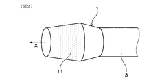
- FIG. 3 is a perspective view of a pipe expansion plug in the first embodiment.
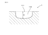
- Explanatory drawing which shows the expanded cross section of the hollow in the advancing direction of the pipe expansion plug in Example 1.
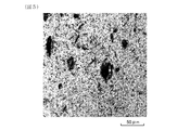
- FIG. 2 is a laser micrograph of the surface of a dimple region of a pipe expansion plug in Example 1.
- the pipe for expanding the tube is used for expanding the aluminum tube by being inserted into the aluminum tube and relatively moving in the axial direction of the aluminum tube.
- the plug for pipe expansion has a slope or a curved surface on the surface for increasing the diameter of the aluminum pipe.
- the pipe expansion plug generally has a region where the outer diameter increases from the front end side in the traveling direction to the rear in the contact region with the inner surface of the aluminum tube.
- the tube expansion plug can be formed in, for example, a spherical shape, an elliptical spherical shape, a bullet shape, a triangular pyramid shape, or a cylindrical shape in which a tapered region is provided in at least a part of the outer shape.
- the maximum diameter of the pipe for expansion is the inner diameter of the expanded aluminum pipe. Therefore, the maximum diameter of the pipe expansion plug can be appropriately set according to the inner diameter of the aluminum pipe, but can be set within a range of 3 to 12 mm, for example.
- the aluminum tube may be made of either pure aluminum or an aluminum alloy.
- the aluminum tube In expanding the tube, the aluminum tube can be arranged horizontally, diagonally, or vertically.
- the expansion plug In the case where the expansion is performed by arranging the aluminum tube obliquely or vertically, it is preferable that the expansion plug is advanced from above to below.
- the tube expansion plug can be used for expansion of an aluminum tube having a linear straight groove formed on the inner surface, or can be used for expansion of an aluminum tube having no inner surface and a smooth inner surface. it can.
- the above-mentioned plug for pipe expansion is used for pipe expansion of an aluminum pipe in which a linear groove extending in the axial direction is formed on the inner surface.
- the above-described advantage that the lubricating oil can be held in the recess formed on the surface of the pipe expansion plug can be sufficiently utilized.
- One linear straight groove may be formed on the inner surface of the aluminum tube, but a plurality of straight grooves may be formed.
- the tube expansion plug has a dimple region on the surface of which a plurality of depressions having an equivalent circle diameter of 3 ⁇ m or more are formed.
- the dimple region is formed in a contact region with the inner surface of the aluminum tube on the surface of the tube expansion plug.
- the dimple region is formed not only from the contact region but also from the front end of the tube expansion plug in the contact region to a further 1 mm or more forward.
- the lubricating oil can be sufficiently held to the front of the contact area during tube expansion processing.
- the dimple region may be formed on the entire surface of the tube expansion plug. In this case, when the depression is formed on the surface of the tube expansion plug, it is not necessary to provide a depression non-formation region, so that design and processing are facilitated.
- the depression in the dimple region has an equivalent circular diameter of the opening of 3 ⁇ m or more.
- the average value D ⁇ m of the depths of these depressions and the average value L ⁇ m of the equivalent circle diameters of the openings of these depressions are 2 ⁇ D ⁇ 100, 10 ⁇ L ⁇ 200 and L / D ⁇ 25 are satisfied.
- the relationship of 2 ⁇ D ⁇ 100, 10 ⁇ L ⁇ 200, and L / D ⁇ 25 is satisfied for the recess having an equivalent circle diameter of 3 ⁇ m or more.
- D ⁇ 2 there is a possibility that the amount of lubricating oil retained in the recess is reduced, and a sufficient amount of lubricating oil cannot be retained in the contact area.
- D> 100 the depth of the recess becomes too large, and the strength of the tube expansion plug itself may be reduced. Therefore, there is a possibility that breakage starting from the depression occurs during tube expansion processing.
- the lubricating oil may be accumulated at the bottom of the depression. Therefore, it may be necessary to increase the supply amount of the lubricating oil in order to sufficiently supply the lubricating oil to the surface of the pipe expansion plug that originally needs the lubricating oil. More preferably, 5 ⁇ D ⁇ 25 is good.
- the depth of the dent is the depth of the deepest part in the dent
- D is the average value of the depth of the deepest part. It should be noted that the depth of the deepest part of each depression having an equivalent circle diameter of 3 ⁇ m or more in the dimple region is measured by microscopic observation, and the average value thereof can be used as the above-described average value D of the depression depths.
- the dent may be filled with aluminum wear powder.
- L> 200 partial adhesion is caused.
- the lubricating oil tends to stay in the recess, and it may be difficult to sufficiently supply the lubricating oil to the surface of the pipe for expansion, which originally needs the lubricating oil.
- the circle-equivalent diameter of the opening is the diameter of the circle assuming a circle having the same area as the area of the opening of the depression. It should be noted that the equivalent circle diameter of the opening of each depression having an equivalent circle diameter of 3 ⁇ m or more in the dimple region is measured by microscopic observation, and the average value thereof can be used as the aforementioned equivalent circle diameter L.
- L / D> 25 the oil easily flows out from the inside of the recess, and it is difficult to sufficiently retain the lubricating oil in the contact area at the time of tube expansion processing. Moreover, there is a risk that the amount of lubricating oil necessary for the pipe expansion process will increase. More preferably, L / D ⁇ 15 is good.
- the area ratio of the opening portion of the recess having the equivalent circle diameter of 3 ⁇ m or more in the dimple region is 10 to 50%.
- the area ratio is less than 10%, a region where the lubricating oil is difficult to be supplied increases in the contact region between the tube for expanding the tube and the aluminum tube at the time of expanding the tube. Therefore, the pipe expansion load becomes large, and it becomes difficult to perform the pipe expansion process sufficiently with a small amount of lubricating oil.
- the area ratio exceeds 50%, the contact area between the surface of the tube for expanding the tube and the inner surface of the aluminum tube is decreased, and the surface pressure may be increased. As a result, adhesion is likely to occur.
- the area ratio is 10 to 40%, more preferably 15 to 30%.
- the area of the openings of all the depressions having an equivalent circle diameter of 3 ⁇ m or more in the dimple region was measured by microscopic observation, and the ratio of the area of the openings of the depressions having an equivalent circle diameter of 3 ⁇ m or more to the total area of the dimple region By calculating (percentage), the area ratio of the opening in the dimple region can be calculated.
- the depression can be formed by, for example, sand blasting or laser processing.
- the shape of the depression is not particularly limited, but the depression can be formed by processing so that the shape of the opening becomes a shape close to, for example, a perfect circle, an ellipse, or a rhombus. Strictly speaking, since it is difficult to form a perfect circle, ellipse, or rhombus, the shape of the opening tends to be indefinite.
- a plurality of depressions may be randomly arranged, or may be arranged in a state of being aligned at a predetermined interval by laser processing, for example. For example, it can arrange
- the material for the pipe expansion plug examples include cemented carbide, tool steel, and ceramics. Cemented carbide or tool steel is preferable.
- the surface of the above-mentioned pipe for expanding pipe may be untreated, but may be subjected to a hard film treatment.
- swelling can be used for the assembly of the heat exchanger which expands the heat exchanger tube which consists of aluminum pipes, for example, and is assembled
- Example 1 Next, an embodiment of the pipe expansion plug will be described.
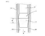
- the tube expansion plug 1 of this example is expanded into the aluminum tube 2 by being relatively advanced in the axial direction of the aluminum tube 2 while being inserted into the aluminum tube 2 supplied with lubricating oil to the inner surface 21.
- a cross section of the aluminum tube 2 is shown, and a side surface of the tube expansion plug 1 is shown.
- the tube expansion plug 1 has a bullet shape made of cemented carbide and has a maximum diameter of 6 mm.
- a shaft rod 3 for advancing the tube expansion plug 1 in the aluminum tube 2 is connected to the rear of the tube expansion plug 1 in the traveling direction X.
- This example is an example in which the aluminum pipe 2 is fixed in the vertical direction, and the pipe expansion plug 1 is advanced from the upper side to the lower side in the vertical direction to perform the pipe expansion.
- the aluminum tube 2 a tube in which a plurality of straight grooves 25 extending in the axial direction are formed on the inner surface 21 is used.
- the contact region S where the surface of the tube for expanding the tube contacts the inner surface of the aluminum tube has a dimple region 11 in which a plurality of depressions 110 are formed.
- the contact region S is expressed with a predetermined width, but in reality, the surface of the tube expansion plug within the range of this width becomes the contact region S.
- a dimple region 11 exists over at least the entire contact region S.
- a dimple region 11 is a region represented by dot hatching.
- the dimple region 11 in this example is formed not only in the contact region S but also in the forward direction X of the tube expansion plug 1 from the front end of the contact region 11 to 1 mm or more forward (see FIG. 1).
- a plurality of depressions 110 are arranged in the dimple region 11 over the entire area. As shown in FIG. 4, each of the recesses 110 has an opening 111 formed in an indefinite shape. In the dimple region 11 of this example, the depressions 110 are randomly arranged (see FIGS. 4 and 5).
- the depression 110 is formed by sandblasting
- FIG. 4 is a schematic diagram of the dimple region showing only the depression 110 having a predetermined size.
- An example of a laser micrograph of the depression 110 in the dimple region 11 actually formed by sandblasting is shown in FIG.
- the depression 110 in this specification refers to an opening having an equivalent circle diameter of 3 ⁇ m or more. Those having an equivalent circle diameter of less than 3 ⁇ m do not correspond to the depression 110.
- the average value D ⁇ m of the depth of these recesses and the average value L ⁇ m of the equivalent circle diameter of the opening of these recesses Satisfies the relationship of 2 ⁇ D ⁇ 100, 10 ⁇ L ⁇ 200, and L / D ⁇ 25, and the area ratio of the opening 111 of these recesses 110 is 10 to 50%.
- the area ratio of the opening 111 of the depression 110 in the dimple region 11 is 20%.
- all irregularities (indentations and portions that are not indentations) on the surface of the dimple region are binarized, and the equivalent circle diameter of each indentation is calculated from the area of all indentations regardless of the equivalent circle diameter.
- a recess having an equivalent circle diameter of 3 ⁇ m or more is extracted.
- the depth of each depression (depth of the deepest part) and the equivalent circle diameter of each depression are calculated, their average values D and L are obtained, and the area ratio of the extracted depressions is calculated. .
- the average depth D is determined by obtaining a 3D profile with a laser microscope and calculating the average depth of the deepest portion of each recess in the dimple region 11 from the profile.
- the average value D ( ⁇ m) of the depth of the recess, the average value L ( ⁇ m) of the equivalent circle diameter of the opening of the recess, L / D, The area ratio (%) value is shown in Table 1 described later.
- the average value D ( ⁇ m) of the depth of the depression, the average value L ( ⁇ m) of the equivalent circle diameter of the opening of the depression, L / D, and the area ratio (%) of the opening of the depression At least one of 21 types of tube expansion plugs (sample 2 to sample 22) different from sample 1 described above was further prepared. Other configurations are the same as those of the sample 1. Samples 2 to 22 were prepared by changing the processing time by sandblasting, the particle size of the abrasive, and the like. For these samples 2 to 22 as well, the depth D ( ⁇ m) of the depression, the equivalent circle diameter L ( ⁇ m), L / D, and the area ratio (%) of the opening are shown in Table 1 described later. In Samples 14 to 16, a hard film is formed on the surface of the pipe for expanding the pipe. The materials are also shown in Table 1. DLC in the table means Diamond Like Carbon.
- a commercially available lubricating oil for aluminum processing (“RF530” manufactured by NSL Bricantz Co., Ltd., kinematic viscosity 2.2 cSt at a temperature of 40 ° C.) is supplied downward from above in the vertical direction. Lubricating oil is supplied to the inner surface 21.
- a tube expansion plug 1 (samples 1 to 22) is inserted into the aluminum tube 2, a predetermined load is applied to the shaft rod 3, and the tube expansion plug 1 is advanced in the axial direction from above in the vertical direction. Tube expansion processing of the aluminum tube 2 is performed.
- Oil quantity evaluation test In the same manner as the pipe expansion load evaluation test, five aluminum pipes are expanded using the pipe expansion plugs (samples 1 to 22). At this time, a predetermined amount of lubricating oil is dropped with a pipette along the inner surface of the aluminum tube, and tube expansion is performed. And after performing the pipe expansion process of five aluminum pipes, the surface of the pipe for pipe expansion was observed with the microscope of 50 times magnification, and the presence or absence of the adhesion of the metal aluminum which has metallic luster was confirmed. By increasing the amount of lubricating oil in the pipe expansion process by 0.1 ml, the amount of lubricating oil necessary for performing the pipe expansion process without causing adhesion of aluminum was determined.
- the tube expansion plug 1 of the samples 1 to 16 has a dimple region 11 in which a plurality of depressions 110 having an equivalent circle diameter of an opening of 3 ⁇ m or more are formed at least in the contact region S.
- the average value D ⁇ m of the depth of 110 and the average value L ⁇ m of the equivalent circle diameter of the opening 111 of the depression 110 satisfy the relationship of 2 ⁇ D ⁇ 100, 10 ⁇ L ⁇ 200, and L / D ⁇ 25 (FIG. 1 to FIG. 5). Further, the area ratio of the opening 111 having an equivalent circle diameter of 3 ⁇ m or more in the dimple region 11 is 10 to 50%.
- the lubricating oil present on the inner surface 21 of the aluminum pipe 2 is held in the depression 110 in the dimple region 11. Therefore, the lubricating oil can be easily held in the contact region S even with a small supply amount. Therefore, the occurrence of image sticking during tube expansion can be sufficiently suppressed. Further, since the lubricating oil can be held in the recess 110, even if the lubricating oil is applied to the aluminum pipe 2 in which the straight groove 25 extending in the axial direction is formed on the inner surface 21, the lubricating oil travels through the straight groove 25. It can suppress discharging.
- the lubricating oil is held in the recess 110, it is easy to supply the lubricating oil to the convex portion of the straight groove 25. Therefore, the lubricating oil can be sufficiently supplied to the contact region S with a small amount of supply even to the aluminum pipe 2 in which the straight groove 25 is formed. Therefore, the occurrence of image sticking or the like can be sufficiently suppressed.
- the pipe expansion plugs of Samples 1 to 16 actually show excellent results in the pipe expansion load and oil amount evaluation tests.
- the depth of the depression is too small. Therefore, it becomes difficult to sufficiently supply the lubricant to the contact area. Moreover, it becomes easy for aluminum abrasion powder to fill a hollow. As a result, the pipe expansion load and the amount of lubricating oil necessary for pipe expansion also increase. Further, in the sample 18, the average value of the equivalent circle diameter of the opening is too small. Therefore, the aluminum wear powder easily fills the recess. As a result, the amount of lubricating oil required for pipe expansion increases. Further, in the sample 19, the average value of the equivalent circle diameters of the openings is too large. Therefore, it becomes easy to create a location where the lubricating oil is not partially introduced in the contact region. As a result, the pipe expansion load and the amount of lubricating oil necessary for pipe expansion also increase.
- the area ratio of the opening in the dimple region is too small. Therefore, the region where the lubricating oil is difficult to be supplied increases in the contact region between the tube expansion plug and the aluminum tube. As a result, the pipe expansion load and the amount of lubricating oil necessary for pipe expansion also increase. Further, in the sample 21, the area ratio of the opening in the dimple region is too large. Therefore, the contact area between the surface of the tube expansion plug and the inner surface of the aluminum tube is reduced, and the surface pressure is increased. As a result, the amount of lubricating oil required for pipe expansion increases. Further, in the sample 22, the equivalent circle diameter of the opening with respect to the depth of the depression is too large.
- a depression was formed on the surface of the tube expansion plug by sandblasting. For this reason, even if the shape of the opening of the depression is approximated to a perfect circle, the shape is actually indefinite (see FIG. 5).
- a depression is formed by laser processing, a depression having an opening of a desired shape can be formed. Thereby, the shape of an opening part can be made into a perfect circle, a rhombus, or a shape close
Landscapes
- Engineering & Computer Science (AREA)
- Mechanical Engineering (AREA)
- Metal Extraction Processes (AREA)
- Pistons, Piston Rings, And Cylinders (AREA)
Abstract
内面(21)に潤滑油を供給したアルミニウム管(2)を拡管させるために用いられる拡管用プラグ(1)である。拡管用プラグ(1)は,その表面がアルミニウム管(2)の内面(21)に接触する接触領域Sに,開口部の円相当径が3μm以上の複数の窪みが形成されたディンプル領域(11)を有する。窪みの深さの平均値Dμmと,窪みの開口部の円相当径の平均値Lμmは,2≦D≦100,10≦L≦200,及びL/D≦25という関係を満足する。ディンプル領域(11)における窪みの開口部の面積率が10~50%である
Description
本発明は、アルミニウム(純アルミニウム及びアルミニウム合金を含む)管を拡管加工する際に用いられる拡管用プラグに関する。
例えば熱交換器においては、内面にらせん状の溝が形成された銅製の伝熱管が用いられている。近年、銅価格の高騰から、伝熱管を銅製からアルミニウム合金製に変更する検討がなされている。
ところが、アルミニウムは、銅に比較して硬度が低いため、銅製の伝熱管のように、らせん状の溝を形成することが困難である。そこで、アルミニウム合金製の伝熱管においては、らせん状の溝ではなく、管の軸方向に伸びるライン状の溝、即ちストレート溝が形成されている。
ところが、アルミニウムは、銅に比較して硬度が低いため、銅製の伝熱管のように、らせん状の溝を形成することが困難である。そこで、アルミニウム合金製の伝熱管においては、らせん状の溝ではなく、管の軸方向に伸びるライン状の溝、即ちストレート溝が形成されている。
熱交換器の組立は、一般的に次のようにして行われている。
まず、所定のカラー部が形成された放熱フィン材を積層し、円筒状のカラー部内に伝熱管を通す。次いで、伝熱管の内側にその内径よりも大きな外径を有する拡管用プラグを強制的に挿入して伝熱管の外径を拡張させるという拡管加工を行うことにより、伝熱管と放熱フィンを固定する。
まず、所定のカラー部が形成された放熱フィン材を積層し、円筒状のカラー部内に伝熱管を通す。次いで、伝熱管の内側にその内径よりも大きな外径を有する拡管用プラグを強制的に挿入して伝熱管の外径を拡張させるという拡管加工を行うことにより、伝熱管と放熱フィンを固定する。
拡管の際には、拡管用プラグと伝熱管との摩擦を低減し、焼き付きの発生を抑制又は防止するために、潤滑油が用いられている。拡管後には、不必要な潤滑油の残存をできる限り減らし、残油量を小さくすることが望まれている。また、コストの低減という観点から、拡管時に使用される潤滑油量の低減が求められている。
これまでに、面粗度が低いセラミックスからなる拡管用プラグが開発されている(特許文献1参照)。また、拡管プラグを固定する芯金の貫通孔に潤滑材を供給する方法が開発されている(特許文献2参照)。また、本体部とその外周表面にダイヤモンドライクカーボン処理(DLC処理)により形成された表面処理層を有する拡管治具が開発されている(特許文献3参照)。
しかしながら、芯金に潤滑油を流す方法を採用すると、潤滑油の粘度などの性状が制限されてしまう。また、芯金に潤滑油が付着するため、コスト的に不利である。
また、セラミックスからなる拡管用プラグを用いると摩擦の低減を図ることが可能であるが、さらなる改良が求められている。
また、DLC処理により表面処理層を形成する方法も、コスト的に不利である。
また、セラミックスからなる拡管用プラグを用いると摩擦の低減を図ることが可能であるが、さらなる改良が求められている。
また、DLC処理により表面処理層を形成する方法も、コスト的に不利である。
拡管加工においては、一般に、潤滑油を予めアルミニウム管の内面に供給し、潤滑油が内面に存在する状態において、拡管用プラグをアルミニウム管内に挿入させる。
ストレート溝が形成されたアルミニウム管に対して、潤滑油を供給して拡管用プラグにより拡管を行うと、導入された潤滑油がストレート溝を伝わって流れ出やすくなる。そのため、アルミニウム管と拡管用プラグとの間に潤滑油を十分に供給させて拡管を行うことが困難になる。また、アルミニウム管の内面に供給された潤滑油は、ストレート溝内に沿って存在する。そのため、ストレート溝の凸部に存在する潤滑油が少なくなり、溝の凸部と拡管用プラグとの摩擦が大きくなりやすい。その結果、焼き付きを引き起こすおそれがある。
ストレート溝が形成されたアルミニウム管に対して、潤滑油を供給して拡管用プラグにより拡管を行うと、導入された潤滑油がストレート溝を伝わって流れ出やすくなる。そのため、アルミニウム管と拡管用プラグとの間に潤滑油を十分に供給させて拡管を行うことが困難になる。また、アルミニウム管の内面に供給された潤滑油は、ストレート溝内に沿って存在する。そのため、ストレート溝の凸部に存在する潤滑油が少なくなり、溝の凸部と拡管用プラグとの摩擦が大きくなりやすい。その結果、焼き付きを引き起こすおそれがある。
本発明は、かかる背景に鑑みてなされたものであって、少量の潤滑油により拡管を行うことができると共に、軸方向に伸びるストレート溝が内面に形成されたアルミニウム管に対しても、アルミニウム管と拡管用プラグとの間に十分に潤滑油を供給して拡管を行うことができる拡管用プラグを提供しようとするものである。
本発明の一態様は、内面に潤滑油を供給したアルミニウム管内に挿入しつつ、該アルミニウム管の軸方向に相対的に進行させて上記アルミニウム管を拡管させるために用いられる拡管用プラグであって、
該拡管用プラグの表面が上記アルミニウム管の内面に接触する接触領域に、開口部の円相当径が3μm以上の複数の窪みが形成されたディンプル領域を有し、
上記窪みの深さの平均値Dμmと、上記窪みの開口部の円相当径の平均値Lμmは、2≦D≦100、10≦L≦200、及びL/D≦25という関係を満足し、
上記ディンプル領域における上記窪みの上記開口部の面積率が10~50%であることを特徴とする拡管用プラグにある。
該拡管用プラグの表面が上記アルミニウム管の内面に接触する接触領域に、開口部の円相当径が3μm以上の複数の窪みが形成されたディンプル領域を有し、
上記窪みの深さの平均値Dμmと、上記窪みの開口部の円相当径の平均値Lμmは、2≦D≦100、10≦L≦200、及びL/D≦25という関係を満足し、
上記ディンプル領域における上記窪みの上記開口部の面積率が10~50%であることを特徴とする拡管用プラグにある。
上記拡管用プラグは、少なくとも上記接触領域に、開口部の円相当径が3μm以上の複数の窪みが形成された上記ディンプル領域を有している。そして、上記のごとく、2≦D≦100、10≦L≦200、及びL/D≦25という関係を満足し、上記ディンプル領域における上記開口部の面積率が10~50%である。そのため、拡管時にアルミニウム管内に拡管用プラグを進行させると、アルミニウム管の内面に存在する潤滑油が、上記ディンプル領域の窪みに保持される。それ故、少量の供給量でも、上記潤滑油を上記接触領域に保持し易くなる。それ故、拡管時における焼き付きの発生を十分に抑制することができる。また、潤滑油を窪み内に保持することができるため、内面に軸方向に伸びるストレート溝が形成されたアルミニウム管に対して適用しても、潤滑油がストレート溝を伝って排出されてしまうことを抑制できる。また、潤滑油が窪み内に保持されるため、ストレート溝の凸部にも潤滑油を供給することができる。そのため、ストレート溝が形成されたアルミニウム管に対しても、少量の供給量で潤滑油を上記接触領域に十分に供給することができる。それ故、焼き付き等の発生を十分に抑制することができる。
次に、上記拡管用プラグの好ましい実施形態について説明する。
上記拡管用プラグは、アルミニウム管内に挿入しつつ、該アルミニウム管の軸方向に相対的に進行させて上記アルミニウム管を拡管させるために用いられる。拡管用プラグは、表面に、上記アルミニウム管の径を大きくするための斜面又は曲面を有している。具体的には、拡管用プラグは、アルミニウム管の内面との接触領域において、一般に、進行方向の先端側から後方に向けて外径が大きくなる領域を有する。より具体的には、拡管用プラグは、例えば球形状、楕円球形、弾丸形状、三角錐形状、又は外形の少なくとも一部にテーパ領域を設けた円柱形状等により構成することができる。一般に、拡管用プラグの最大径が拡管後のアルミニウム管の内径となる。したがって、拡管用プラグの最大径は、アルミニウム管の内径に応じて適宜設定することができるが、例えば3~12mmの範囲に設定することができる。
上記拡管用プラグは、アルミニウム管内に挿入しつつ、該アルミニウム管の軸方向に相対的に進行させて上記アルミニウム管を拡管させるために用いられる。拡管用プラグは、表面に、上記アルミニウム管の径を大きくするための斜面又は曲面を有している。具体的には、拡管用プラグは、アルミニウム管の内面との接触領域において、一般に、進行方向の先端側から後方に向けて外径が大きくなる領域を有する。より具体的には、拡管用プラグは、例えば球形状、楕円球形、弾丸形状、三角錐形状、又は外形の少なくとも一部にテーパ領域を設けた円柱形状等により構成することができる。一般に、拡管用プラグの最大径が拡管後のアルミニウム管の内径となる。したがって、拡管用プラグの最大径は、アルミニウム管の内径に応じて適宜設定することができるが、例えば3~12mmの範囲に設定することができる。
アルミニウム管は、純アルミニウム、又はアルミニウム合金のいずれからなるものであってもよい。
拡管にあたっては、アルミニウム管は、水平、斜め、又は鉛直方向に配置することができる。アルミニウム管を斜め又は鉛直方向に配置して拡管を行う場合には、上方から下方へ向けて上記拡管用プラグを進行させることが好ましい。また、比較的長尺なアルミニウム管については、アルミニウム管を水平又は水平に近い状態に配置して拡管を行うことが好ましい。
拡管にあたっては、アルミニウム管は、水平、斜め、又は鉛直方向に配置することができる。アルミニウム管を斜め又は鉛直方向に配置して拡管を行う場合には、上方から下方へ向けて上記拡管用プラグを進行させることが好ましい。また、比較的長尺なアルミニウム管については、アルミニウム管を水平又は水平に近い状態に配置して拡管を行うことが好ましい。
上記拡管用プラグは、内面にライン状のストレート溝が形成されたアルミニウム管の拡管に用いることもできるし、内面に溝が形成されておらず、内面が平滑なアルミニウム管の拡管に用いることもできる。
好ましくは、上記拡管用プラグは、軸方向に伸びるライン状の溝が内面に形成されたアルミニウム管の拡管に用いられることがよい。
この場合には、上記拡管用プラグの表面に形成された窪み内に潤滑油を保持できるという上述の利点を十分にいかすことができる。
アルミニウム管の内面に形成されるライン状のストレート溝は、1つでもよいが、複数形成されていてもよい。
好ましくは、上記拡管用プラグは、軸方向に伸びるライン状の溝が内面に形成されたアルミニウム管の拡管に用いられることがよい。
この場合には、上記拡管用プラグの表面に形成された窪み内に潤滑油を保持できるという上述の利点を十分にいかすことができる。
アルミニウム管の内面に形成されるライン状のストレート溝は、1つでもよいが、複数形成されていてもよい。
また、上記拡管用プラグは、その表面に開口部の円相当径が3μm以上の複数の窪みが形成されたディンプル領域を有する。ディンプル領域は、拡管プラグの表面におけるアルミニウム管の内面との接触領域に形成されている。
好ましくは、上記ディンプル領域は、上記接触領域だけでなく、該接触領域における上記拡管用プラグの進行方向の前端からさらに1mm以上前方まで形成されていることがよい。
この場合には、拡管加工時に上記接触領域の前方にまで十分に潤滑油を保持させることができる。
また、ディンプル領域は、拡管用プラグの表面全体に形成されていてもよい。この場合には、拡管用プラグの表面に窪みを形成する際に、窪みの非形成領域を設ける必要がなくなるため、設計及び加工が容易になる。
好ましくは、上記ディンプル領域は、上記接触領域だけでなく、該接触領域における上記拡管用プラグの進行方向の前端からさらに1mm以上前方まで形成されていることがよい。
この場合には、拡管加工時に上記接触領域の前方にまで十分に潤滑油を保持させることができる。
また、ディンプル領域は、拡管用プラグの表面全体に形成されていてもよい。この場合には、拡管用プラグの表面に窪みを形成する際に、窪みの非形成領域を設ける必要がなくなるため、設計及び加工が容易になる。
上記ディンプル領域における上記窪みは、開口部の円相当径が3μm以上のものである。そして、上記円相当径が3μm以上の全ての窪みについて、これらの窪みの深さの平均値Dμmと、これらの窪みの開口部の円相当径の平均値Lμmは、2≦D≦100、10≦L≦200、及びL/D≦25という関係を満足する。ディンプル領域には、開口部の円相当径が3μm未満という小さな窪みが存在してもよいが、これら小さな窪みは本発明における窪みには該当しない。上記ディンプル領域においては、上記のごとく、円相当径が3μm以上の窪みについて、2≦D≦100、10≦L≦200、及びL/D≦25という関係を満足する。
D<2の場合には、窪み内の潤滑油の保持量が少なくなり、接触領域に十分量の潤滑油を保持させることができなくなるおそれがある。一方、D>100の場合には、窪みの深さが大きくなりすぎて、拡管用プラグ自体の強度が低下するおそれがある。そのため、拡管加工中に窪みを起点とした破断が発生するおそれがある。また、100μmを超える大きな深さの窪みを形成すると、潤滑油が窪みの底に貯まってしまうおそれがある。そのため、本来潤滑油が必要な拡管用プラグの表面に潤滑油を十分に供給するために、潤滑油の供給量を増やす必要性が生じるおそれがある。より好ましくは、5≦D≦25がよい。
窪みの深さは、窪みにおける最深部の深さであり、Dは最深部の深さの平均値である。なお、ディンプル領域における円相当径3μm以上の各窪みの最深部の深さを顕微鏡観察により測定し、その平均値をもって上述の窪みの深さの平均値Dとすることができる。
D<2の場合には、窪み内の潤滑油の保持量が少なくなり、接触領域に十分量の潤滑油を保持させることができなくなるおそれがある。一方、D>100の場合には、窪みの深さが大きくなりすぎて、拡管用プラグ自体の強度が低下するおそれがある。そのため、拡管加工中に窪みを起点とした破断が発生するおそれがある。また、100μmを超える大きな深さの窪みを形成すると、潤滑油が窪みの底に貯まってしまうおそれがある。そのため、本来潤滑油が必要な拡管用プラグの表面に潤滑油を十分に供給するために、潤滑油の供給量を増やす必要性が生じるおそれがある。より好ましくは、5≦D≦25がよい。
窪みの深さは、窪みにおける最深部の深さであり、Dは最深部の深さの平均値である。なお、ディンプル領域における円相当径3μm以上の各窪みの最深部の深さを顕微鏡観察により測定し、その平均値をもって上述の窪みの深さの平均値Dとすることができる。
また、L<10の場合には、窪みがアルミ摩耗粉で埋まってしまうおそれがある。一方、L>200の場合には、部分的な凝着の原因となる。また、この場合には、窪み内に潤滑油が入り込んだままとどまり易くなり、本来潤滑油が必要な拡管用プラグの表面に潤滑油を十分に供給することが困難になるおそれがある。より好ましくは30≦L≦80がよい。
開口部の円相当径は、窪みの開口部の面積と同面積の円を想定し、その円の直径である。なお、ディンプル領域における円相当径3μm以上の各窪みの開口部の円相当径を顕微鏡観察により測定し、その平均値をもって上述の円相当径Lとすることができる。
開口部の円相当径は、窪みの開口部の面積と同面積の円を想定し、その円の直径である。なお、ディンプル領域における円相当径3μm以上の各窪みの開口部の円相当径を顕微鏡観察により測定し、その平均値をもって上述の円相当径Lとすることができる。
また、L/D>25の場合には、窪み内から油が流出し易くなり、拡管加工時に、接触領域に潤滑油を十分保持させることが困難になる。また、拡管加工に必要な潤滑油量が増大してしまうおそれがある。より好ましくは、L/D≦15がよい。
また、ディンプル領域における上記円相当径が3μm以上の上記窪みの開口部の面積率は、10~50%である。
面積率が10%未満の場合には、拡管加工時に、拡管用プラグとアルミニウム管との接触領域に潤滑油が供給されにくい領域が増大する。そのため、拡管荷重が大きくなり、少ない潤滑油量で十分に拡管加工を行うことが困難になる。一方、面積率が50%を超える場合には、拡管用プラグの表面とアルミニウム管の内面との接触面積が少なくなり、かえって面圧が大きくなってしまうおそれがある。その結果、凝着が発生し易くなる。より好ましくは、面積率は10~40%がよく、さらに好ましくは15~30%がよい。
なお、ディンプル領域における上記円相当径が3μm以上のすべての窪みの開口部の面積を顕微鏡観察により測定し、ディンプル領域の全面積に対する上記円相当径が3μm以上の窪みの開口部の面積の割合(百分率)を算出することにより、ディンプル領域における開口部の面積率を算出することができる。
面積率が10%未満の場合には、拡管加工時に、拡管用プラグとアルミニウム管との接触領域に潤滑油が供給されにくい領域が増大する。そのため、拡管荷重が大きくなり、少ない潤滑油量で十分に拡管加工を行うことが困難になる。一方、面積率が50%を超える場合には、拡管用プラグの表面とアルミニウム管の内面との接触面積が少なくなり、かえって面圧が大きくなってしまうおそれがある。その結果、凝着が発生し易くなる。より好ましくは、面積率は10~40%がよく、さらに好ましくは15~30%がよい。
なお、ディンプル領域における上記円相当径が3μm以上のすべての窪みの開口部の面積を顕微鏡観察により測定し、ディンプル領域の全面積に対する上記円相当径が3μm以上の窪みの開口部の面積の割合(百分率)を算出することにより、ディンプル領域における開口部の面積率を算出することができる。
窪みは、例えばサンドブラスト又はレーザー加工により形成することができる。窪みの形状は特に限定されることはないが、開口部の形状が例えば真円、楕円、又は菱形に近い形状になるように加工を行って、窪みを形成することができる。厳密には、完全な真円、楕円、又は菱形にすることは困難であるため、開口部の形状は不定形となりやすい。
また、ディンプル領域においては、複数の窪みをランダムに配置してもよいし、例えばレーザー加工により、所定の間隔で整列させた状態で配置してもよい。例えば格子状又は千鳥状に配置させることができる。
上記拡管用プラグの材質としては、例えば超硬合金、工具鋼、セラミックスなどがある。好ましくは、超硬合金又は工具鋼がよい。
また、上記拡管用プラグの表面は、無処理でもよいが、硬質皮膜処理が施されていてもよい。
また、上記拡管用プラグは、例えばアルミニウム管よりなる伝熱管を拡管させて放熱フィンに組み付けるという熱交換器の組立に用いることができる。
また、上記拡管用プラグの表面は、無処理でもよいが、硬質皮膜処理が施されていてもよい。
また、上記拡管用プラグは、例えばアルミニウム管よりなる伝熱管を拡管させて放熱フィンに組み付けるという熱交換器の組立に用いることができる。
(実施例1)
次に、拡管用プラグの実施例について、説明する。
図1に示すごとく、本例の拡管用プラグ1は、内面21に潤滑油を供給したアルミニウム管2内に挿入しつつ、アルミニウム管2の軸方向に相対的に進行させてアルミニウム管2を拡管させるために用いられる。なお、図1においては、説明の便宜のため、アルミニウム管2についてはその断面を示し、拡管用プラグ1についてはその側面を示している。
次に、拡管用プラグの実施例について、説明する。
図1に示すごとく、本例の拡管用プラグ1は、内面21に潤滑油を供給したアルミニウム管2内に挿入しつつ、アルミニウム管2の軸方向に相対的に進行させてアルミニウム管2を拡管させるために用いられる。なお、図1においては、説明の便宜のため、アルミニウム管2についてはその断面を示し、拡管用プラグ1についてはその側面を示している。
図1及び図2に示すごとく、拡管用プラグ1は、超硬合金製の弾丸形状であり、その最大径は6mmである。拡管用プラグ1の進行方向Xの後方には、アルミニウム管2内において拡管用プラグ1を進行させるための軸棒3が連結されている。
本例は、アルミニウム管2を鉛直方向に固定し、拡管用プラグ1を鉛直方向の上方から下方へ進行させて拡管を行う例である。アルミニウム管2としては、軸方向に伸びる複数のストレート溝25が内面21に形成された管を用いる。
図1~図4に示すごとく、拡管用プラグの表面が上記アルミニウム管の内面に接触する接触領域Sには、複数の窪み110が形成されたディンプル領域11を有する。なお、図1において、接触領域Sは、所定の幅で表現されているが、実際にはこの幅の範囲内にある拡管用プラグの表面が接触領域Sとなる。
そして、少なくとも接触領域Sの全域にわたって、ディンプル領域11が存在する。図1において、ディンプル領域11は、ドットハッチングを付けて表した領域である。本例におけるディンプル領域11は、接触領域Sだけでなく、拡管用プラグ1の進行方向Xにおける接触領域11の前端からさらに1mm以上前方にまで形成されている(図1参照)。ディンプル領域11には、その全域にわたって複数の窪み110が配置されている。図4に示すごとく、窪み110はそれぞれ開口部111が不定形で形成されている。本例のディンプル領域11において、窪み110は、ランダムに配置されている(図4、図5参照)。
そして、少なくとも接触領域Sの全域にわたって、ディンプル領域11が存在する。図1において、ディンプル領域11は、ドットハッチングを付けて表した領域である。本例におけるディンプル領域11は、接触領域Sだけでなく、拡管用プラグ1の進行方向Xにおける接触領域11の前端からさらに1mm以上前方にまで形成されている(図1参照)。ディンプル領域11には、その全域にわたって複数の窪み110が配置されている。図4に示すごとく、窪み110はそれぞれ開口部111が不定形で形成されている。本例のディンプル領域11において、窪み110は、ランダムに配置されている(図4、図5参照)。
本例において、窪み110は、サンドブラストにより形成されており、図4は、所定の大きさの窪み110のみを示したディンプル領域の概略図である。実際にサンドブラストにより形成されたディンプル領域11における窪み110のレーザー顕微鏡写真の一例を図5に示す。同図に示すごとく、サンドブラストにより形成された窪みには大小様々なものが存在するが、本明細書における窪み110は、開口部の円相当径が3μm以上のものをいう。円相当径が3μm未満のものは、窪み110に該当しない。実施例にかかる拡管用プラグ1においては、開口部の円相当径が3μm以上の窪みについて、これらの窪みの深さの平均値Dμmと、これらの窪みの開口部の円相当径の平均値Lμmが2≦D≦100、10≦L≦200、L/D≦25という関係を満足し、これらの窪み110の開口部111の面積率が10~50%にある。
本例の拡管用プラグ1(試料1)において、図3に示すごとく、窪み110の深さの平均値D(最深部の深さの平均値)は、D=2μmであり、窪み110の開口部111の円相当径の平均値Lは、L=50μmである。また、ディンプル領域11における窪み110の開口部111の面積率は20%である。
これらの深さ、円相当径、面積率は、オリンパス(株)製のレーザー顕微鏡(OLS3000)による顕微鏡観察により求めることができる。より具体的には、ディンプル領域の表面における全ての凹凸(窪みと窪みでない部分)を2値化し、円相当径を問わずに全ての窪みの面積から各窪みの円相当径を算出する。次いで、円相当径が3μm以上の窪みを抽出する。抽出した全ての窪みについて、各窪みの深さ(最深部の深さ)、各窪みの円相当径を算出し、これらの平均値D、Lを求め、さらに抽出した窪みの面積率を算出する。なお、窪みの深さの平均値Dは、レーザー顕微鏡により3Dプロファイルを得て、そのプロファイルからディンプル領域11における各窪みの最深部の深さの平均値を算出することにより決定する。
これらの深さ、円相当径、面積率は、オリンパス(株)製のレーザー顕微鏡(OLS3000)による顕微鏡観察により求めることができる。より具体的には、ディンプル領域の表面における全ての凹凸(窪みと窪みでない部分)を2値化し、円相当径を問わずに全ての窪みの面積から各窪みの円相当径を算出する。次いで、円相当径が3μm以上の窪みを抽出する。抽出した全ての窪みについて、各窪みの深さ(最深部の深さ)、各窪みの円相当径を算出し、これらの平均値D、Lを求め、さらに抽出した窪みの面積率を算出する。なお、窪みの深さの平均値Dは、レーザー顕微鏡により3Dプロファイルを得て、そのプロファイルからディンプル領域11における各窪みの最深部の深さの平均値を算出することにより決定する。
本例の拡管用プラグ1(試料1)について、窪みの深さの平均値D(μm)、窪みの開口部の円相当径の平均値L(μm)、L/D、窪みの開口部の面積率(%)の値を後述の表1に示す。
また、本例においては、窪みの深さの平均値D(μm)、窪みの開口部の円相当径の平均値L(μm)、L/D、窪みの開口部の面積率(%)の少なくともいずれかが、上述の試料1とは異なる21種類の拡管用プラグ(試料2~試料22)をさらに準備した。その他の構成は試料1と同様である。これらの試料2~22は、サンドブラストによる処理時間や研磨材の粒径等を変更することにより作製した。これらの試料2~22についても、窪みの深さD(μm)、開口部の円相当径L(μm)、L/D、開口部の面積率(%)を後述の表1に示す。
なお、試料14~16においては、拡管用プラグの表面に硬質皮膜を形成してある。その材質を表1に併記する。表中のDLCは、ダイヤモンド・ライク・カーボン(Diamond Like Carbon)を意味する。
なお、試料14~16においては、拡管用プラグの表面に硬質皮膜を形成してある。その材質を表1に併記する。表中のDLCは、ダイヤモンド・ライク・カーボン(Diamond Like Carbon)を意味する。

次に、各試料の拡管用プラグを用いて、拡管荷重及び油量の評価試験を行った。
「拡管荷重評価試験」
最大径φ6mmの拡管用プラグ(試料1~24)を用いて、外径:7.0mm、内面ストレート溝付のJIS A3003のアルミニウム合金管(アルミニウム管)を作製する。アルミニウム管は、溝深さ(フィン高さ):300μm、底肉厚(溝底から外周面までの肉厚):475μmである。
具体的には、図1に示すごとく、軸方向に伸びる複数のストレート溝25が内面21に形成されたアルミニウム管2をその軸方向が鉛直方向になるように固定する。そして、市販のアルミニウム加工用の潤滑油(エヌ・エス ルブリカンツ(株)製の「RF530」、温度40℃における動粘度2.2cSt)を鉛直方向の上方から下方へ向けて供給し、アルミニウム管2の内面21に潤滑油を供給する。次いで、アルミニウム管2内に拡管用プラグ1(試料1~22)を挿入し、軸棒3に所定の荷重をかけて拡管用プラグ1を鉛直方向の上方から下方へ軸方向に進行させて、アルミニウム管2の拡管加工を行う。
「拡管荷重評価試験」
最大径φ6mmの拡管用プラグ(試料1~24)を用いて、外径:7.0mm、内面ストレート溝付のJIS A3003のアルミニウム合金管(アルミニウム管)を作製する。アルミニウム管は、溝深さ(フィン高さ):300μm、底肉厚(溝底から外周面までの肉厚):475μmである。
具体的には、図1に示すごとく、軸方向に伸びる複数のストレート溝25が内面21に形成されたアルミニウム管2をその軸方向が鉛直方向になるように固定する。そして、市販のアルミニウム加工用の潤滑油(エヌ・エス ルブリカンツ(株)製の「RF530」、温度40℃における動粘度2.2cSt)を鉛直方向の上方から下方へ向けて供給し、アルミニウム管2の内面21に潤滑油を供給する。次いで、アルミニウム管2内に拡管用プラグ1(試料1~22)を挿入し、軸棒3に所定の荷重をかけて拡管用プラグ1を鉛直方向の上方から下方へ軸方向に進行させて、アルミニウム管2の拡管加工を行う。
拡管荷重の評価にあたっては、長さ100mmのアルミニウム管を5本準備し、1本のアルミニウム管に対して0.5mlの潤滑油を用いる。ピペットを用いてアルミニウム管の端部に潤滑油を塗り、アルミニウム管の外部を拘束せずに、管内に各試料の拡管用プラグを挿入することにより上述のごとく拡管を行う。アルミニウム管2内における拡管用プラグ1の移動速度(拡管速度)は、50mm/minとする。そして、拡管を5本のアルミニウム管について連続して行い、拡管プラグの合計移動距離100~500mmの範囲、即ち、2本目のはじめから5本目のおわりまでの拡管に必要な平均荷重(拡管荷重)を測定した。そして、表面にディンプル領域が全く形成されていない拡管用プラグを用いて同様の拡管加工を行い、ディンプル領域のない拡管用プラグよりも拡管荷重が10%以上低下した場合を○として評価し、10%未満しか低下しなかった場合を×として評価した。その結果を表2に示す。
「油量評価試験」
拡管荷重の評価試験と同様にして、拡管用プラグ(試料1~22)を用いて5本のアルミニウム管の拡管加工を行う。このとき、所定量の潤滑油をアルミニウム管の内面に沿ってピペットで滴下し、拡管加工を行う。そして、5本のアルミニウム管の拡管加工を行った後に、拡管用プラグの表面を倍率50倍の顕微鏡にて観察し、金属光沢を有する金属アルミニウムの凝着の有無を確認した。拡管加工における潤滑油量を0.1mlずつ増加させることにより、アルミニウムの凝着を起こすことなく拡管加工を行うために必要な潤滑油量を決定した。必要な潤滑油量が0.5ml以下の場合を◎として評価した。また、必要な潤滑油量が0.5mlを超えかつ1ml未満の場合を○として評価した。また、必要な潤滑油量が1ml以上の場合を×として評価した。その結果を表2に示す。
拡管荷重の評価試験と同様にして、拡管用プラグ(試料1~22)を用いて5本のアルミニウム管の拡管加工を行う。このとき、所定量の潤滑油をアルミニウム管の内面に沿ってピペットで滴下し、拡管加工を行う。そして、5本のアルミニウム管の拡管加工を行った後に、拡管用プラグの表面を倍率50倍の顕微鏡にて観察し、金属光沢を有する金属アルミニウムの凝着の有無を確認した。拡管加工における潤滑油量を0.1mlずつ増加させることにより、アルミニウムの凝着を起こすことなく拡管加工を行うために必要な潤滑油量を決定した。必要な潤滑油量が0.5ml以下の場合を◎として評価した。また、必要な潤滑油量が0.5mlを超えかつ1ml未満の場合を○として評価した。また、必要な潤滑油量が1ml以上の場合を×として評価した。その結果を表2に示す。
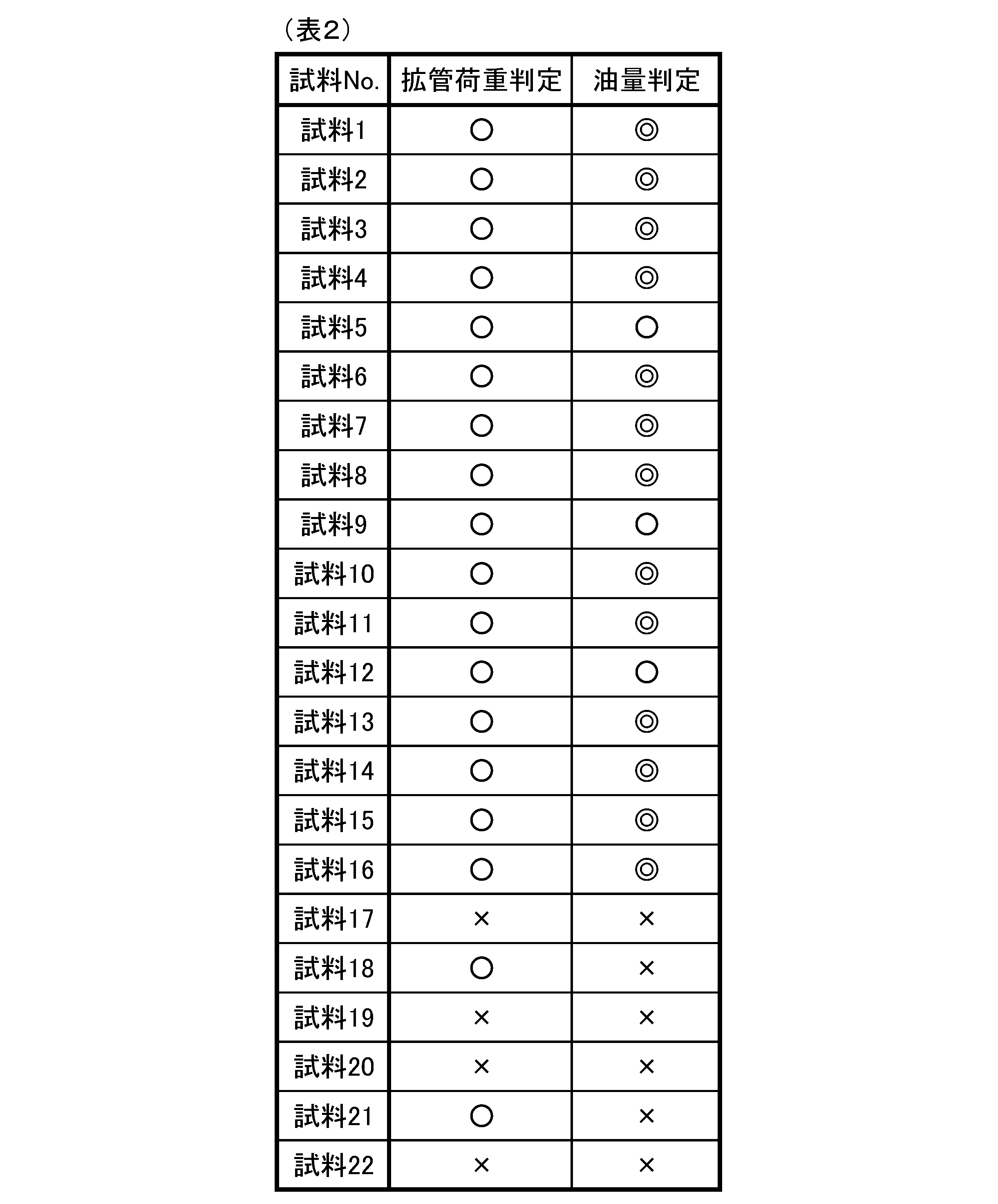
表1より知られるごとく、試料1~16の拡管用プラグ1は、少なくとも接触領域Sに、開口部の円相当径が3μm以上の複数の窪み110が形成されたディンプル領域11を有し、窪み110の深さの平均値Dμmと、窪み110の開口部111の円相当径の平均値Lμmが2≦D≦100、10≦L≦200、及びL/D≦25という関係を満足する(図1~図5参照)。さらに、ディンプル領域11における円相当径が3μm以上の開口部111の面積率が10~50%である。
そのため、図1に示すごとく、拡管時にアルミニウム管2内に拡管用プラグ1を進行させると、アルミニウム管2の内面21に存在する潤滑油が、ディンプル領域11の窪み110に保持される。それ故、少量の供給量でも、潤滑油を接触領域Sに保持し易くなる。それ故、拡管時における焼き付きの発生を十分に抑制することができる。また、潤滑油を窪み110内に保持することができるため、内面21に軸方向に伸びるストレート溝25が形成されたアルミニウム管2に対して適用しても、潤滑油がストレート溝25を伝って排出されてしまうことを抑制できる。また、潤滑油が窪み110内に保持されるため、ストレート溝25の凸部にも潤滑油を供給し易くなる。そのため、ストレート溝25が形成されたアルミニウム管2に対しても、少量の供給量で潤滑油を接触領域Sに十分に供給することができる。それ故、焼き付き等の発生を十分に抑制することができる。
表2より知られるごとく、試料1~16の拡管用プラグは、実際に拡管荷重及び油量の評価試験において優れた結果を示している。
表2より知られるごとく、試料1~16の拡管用プラグは、実際に拡管荷重及び油量の評価試験において優れた結果を示している。
一方、試料17は、窪みの深さが小さすぎる。そのため、接触領域に十分に潤滑油を供給することが困難になる。また、アルミニウム摩耗粉が窪みを埋めてしまい易くなる。その結果、拡管荷重も拡管に必要な潤滑油量も増大してしまう。
また、試料18は、開口部の円相当径の平均値が小さすぎる。そのため、アルミニウム摩耗粉が窪みを埋めてしまい易くなる。その結果、拡管に必要な潤滑油量が増大してしまう。
また、試料19は、開口部の円相当径の平均値が大きすぎる。そのため、接触領域において部分的に潤滑油が導入されない箇所ができやすくなる。その結果、拡管荷重も拡管に必要な潤滑油量も増大してしまう。
また、試料18は、開口部の円相当径の平均値が小さすぎる。そのため、アルミニウム摩耗粉が窪みを埋めてしまい易くなる。その結果、拡管に必要な潤滑油量が増大してしまう。
また、試料19は、開口部の円相当径の平均値が大きすぎる。そのため、接触領域において部分的に潤滑油が導入されない箇所ができやすくなる。その結果、拡管荷重も拡管に必要な潤滑油量も増大してしまう。
また、試料20は、ディンプル領域における開口部の面積率が小さすぎる。そのため、拡管用プラグとアルミニウム管との接触領域に潤滑油が供給されにくい領域が増大する。その結果、拡管荷重も拡管に必要な潤滑油量も増大してしまう。
また、試料21は、ディンプル領域における開口部の面積率が大きすぎる。そのため、拡管用プラグの表面とアルミニウム管の内面との接触面積が少なくなり、かえって面圧が大きくなってしまう。その結果、拡管に必要な潤滑油量が増大してしまう。
また、試料22は、窪みの深さに対する開口部の円相当径が大きすぎる。そのため、窪み内から油が流出し易くなり、拡管加工時に、接触領域に潤滑油を十分保持させることが困難になる。その結果、拡管荷重も拡管に必要な潤滑油量も増大してしまう。
また、試料21は、ディンプル領域における開口部の面積率が大きすぎる。そのため、拡管用プラグの表面とアルミニウム管の内面との接触面積が少なくなり、かえって面圧が大きくなってしまう。その結果、拡管に必要な潤滑油量が増大してしまう。
また、試料22は、窪みの深さに対する開口部の円相当径が大きすぎる。そのため、窪み内から油が流出し易くなり、拡管加工時に、接触領域に潤滑油を十分保持させることが困難になる。その結果、拡管荷重も拡管に必要な潤滑油量も増大してしまう。
なお、本例においては、サンドブラストにより拡管用プラグの表面に窪みを形成した。そのため、窪みの開口部の形状を真円に近づけようとしても、実際には不定形となる(図5参照)。例えばレーザー加工により窪みを形成すると、所望の形状の開口部を有する窪みを形成することが可能になる。これにより、開口部の形状を例えば真円、菱形、又はこれらに近い形状にすることができる。
Claims (3)
- 内面に潤滑油を供給したアルミニウム管内に挿入しつつ、該アルミニウム管の軸方向に相対的に進行させて上記アルミニウム管を拡管させるために用いられる拡管用プラグであって、
該拡管用プラグの表面が上記アルミニウム管の内面に接触する接触領域に、開口部の円相当径が3μm以上の複数の窪みが形成されたディンプル領域を有し、
上記窪みの深さの平均値Dμmと、上記窪みの開口部の円相当径の平均値Lμmは、2≦D≦100、10≦L≦200、及びL/D≦25という関係を満足し、
上記ディンプル領域における上記窪みの上記開口部の面積率が10~50%であることを特徴とする拡管用プラグ。 - 請求項1に記載の拡管用プラグにおいて、軸方向に伸びるライン状のストレート溝が内面に形成されたアルミニウム管の拡管に用いられることを特徴とする拡管用プラグ。
- 請求項1又は2に記載の拡管用プラグにおいて、上記ディンプル領域は、上記接触領域だけでなく、該接触領域における上記拡管用プラグの進行方向の前端からさらに1mm以上前方まで形成されていることを特徴とする拡管用プラグ。
Priority Applications (1)
| Application Number | Priority Date | Filing Date | Title |
|---|---|---|---|
| JP2014524701A JP6106171B2 (ja) | 2012-07-13 | 2013-06-14 | 拡管用プラグ |
Applications Claiming Priority (2)
| Application Number | Priority Date | Filing Date | Title |
|---|---|---|---|
| JP2012157048 | 2012-07-13 | ||
| JP2012-157048 | 2012-07-13 |
Publications (1)
| Publication Number | Publication Date |
|---|---|
| WO2014010366A1 true WO2014010366A1 (ja) | 2014-01-16 |
Family
ID=49915834
Family Applications (1)
| Application Number | Title | Priority Date | Filing Date |
|---|---|---|---|
| PCT/JP2013/066458 Ceased WO2014010366A1 (ja) | 2012-07-13 | 2013-06-14 | 拡管用プラグ |
Country Status (3)
| Country | Link |
|---|---|
| JP (1) | JP6106171B2 (ja) |
| CN (2) | CN203578594U (ja) |
| WO (1) | WO2014010366A1 (ja) |
Cited By (2)
| Publication number | Priority date | Publication date | Assignee | Title |
|---|---|---|---|---|
| JP2021137835A (ja) * | 2020-03-04 | 2021-09-16 | 日本製鉄株式会社 | 差厚管の製造装置及び差厚管の製造方法 |
| JP7745860B1 (ja) * | 2025-04-25 | 2025-09-30 | ニッシン・パーテクチュアル株式会社 | パンチおよびパンチの製造方法 |
Families Citing this family (2)
| Publication number | Priority date | Publication date | Assignee | Title |
|---|---|---|---|---|
| WO2014010366A1 (ja) * | 2012-07-13 | 2014-01-16 | 住友軽金属工業株式会社 | 拡管用プラグ |
| US11440072B2 (en) | 2019-03-28 | 2022-09-13 | Carrier Corporation | Tube bending mandrel and system using the same |
Citations (3)
| Publication number | Priority date | Publication date | Assignee | Title |
|---|---|---|---|---|
| JPH06210370A (ja) * | 1993-01-19 | 1994-08-02 | Mazda Motor Corp | プレス成形用金型 |
| JP2000117362A (ja) * | 1998-10-12 | 2000-04-25 | Hitachi Cable Ltd | 金属管の拡管用マンドレル及び拡管方法 |
| WO2009131072A1 (ja) * | 2008-04-24 | 2009-10-29 | 三菱電機株式会社 | 熱交換器、及びこの熱交換器を用いた空気調和機 |
Family Cites Families (6)
| Publication number | Priority date | Publication date | Assignee | Title |
|---|---|---|---|---|
| JPH02182330A (ja) * | 1989-01-10 | 1990-07-17 | Mitsubishi Metal Corp | セラミックス製拡管用プラグ |
| CA2218786C (en) * | 1996-10-18 | 2005-12-06 | Andrew Van Doorn | Solar panel and method of manufacturing thereof |
| JP3783325B2 (ja) * | 1997-03-19 | 2006-06-07 | アイシン精機株式会社 | パイプ曲げ加工装置 |
| CN1330576A (zh) * | 1999-11-10 | 2002-01-09 | 日高精机株式会社 | 热交换器用传热管的扩管方法及扩管装置 |
| JP5436751B2 (ja) * | 2006-10-13 | 2014-03-05 | 株式会社Uacj | 金属管の拡管方法、それに用いる拡管冶具、及びそれに用いる潤滑油 |
| WO2014010366A1 (ja) * | 2012-07-13 | 2014-01-16 | 住友軽金属工業株式会社 | 拡管用プラグ |
-
2013
- 2013-06-14 WO PCT/JP2013/066458 patent/WO2014010366A1/ja not_active Ceased
- 2013-06-14 JP JP2014524701A patent/JP6106171B2/ja not_active Expired - Fee Related
- 2013-07-12 CN CN201320413830.8U patent/CN203578594U/zh not_active Expired - Lifetime
- 2013-07-12 CN CN201310293516.5A patent/CN103537573B/zh not_active Expired - Fee Related
Patent Citations (3)
| Publication number | Priority date | Publication date | Assignee | Title |
|---|---|---|---|---|
| JPH06210370A (ja) * | 1993-01-19 | 1994-08-02 | Mazda Motor Corp | プレス成形用金型 |
| JP2000117362A (ja) * | 1998-10-12 | 2000-04-25 | Hitachi Cable Ltd | 金属管の拡管用マンドレル及び拡管方法 |
| WO2009131072A1 (ja) * | 2008-04-24 | 2009-10-29 | 三菱電機株式会社 | 熱交換器、及びこの熱交換器を用いた空気調和機 |
Cited By (3)
| Publication number | Priority date | Publication date | Assignee | Title |
|---|---|---|---|---|
| JP2021137835A (ja) * | 2020-03-04 | 2021-09-16 | 日本製鉄株式会社 | 差厚管の製造装置及び差厚管の製造方法 |
| JP7436814B2 (ja) | 2020-03-04 | 2024-02-22 | 日本製鉄株式会社 | 差厚管の製造装置及び差厚管の製造方法 |
| JP7745860B1 (ja) * | 2025-04-25 | 2025-09-30 | ニッシン・パーテクチュアル株式会社 | パンチおよびパンチの製造方法 |
Also Published As
| Publication number | Publication date |
|---|---|
| CN103537573A (zh) | 2014-01-29 |
| JP6106171B2 (ja) | 2017-03-29 |
| CN203578594U (zh) | 2014-05-07 |
| JPWO2014010366A1 (ja) | 2016-06-20 |
| CN103537573B (zh) | 2017-04-19 |
Similar Documents
| Publication | Publication Date | Title |
|---|---|---|
| JP6106171B2 (ja) | 拡管用プラグ | |
| Fatima et al. | A comparative study on cutting performance of rake-flank face structured cutting tool in orthogonal cutting of AISI/SAE 4140 | |
| CN104481420B (zh) | 一种新型抽油杆接箍及其制备工艺 | |
| JP6173317B2 (ja) | 拡管用プラグ | |
| CN104619434B (zh) | 无缝钢管的轧制用顶头、该顶头的制造方法以及使用该顶头的无缝钢管的制造方法 | |
| JP2009242837A (ja) | 工具磨耗低減銅合金鋳塊及び銅合金管 | |
| JP2009243715A (ja) | 漏洩検知管および熱交換器 | |
| WO2013153972A1 (ja) | アルミニウム合金製内面溝付き伝熱管 | |
| CN106734438A (zh) | 一种带小曲率弯曲半径l型薄壁铝合金弯管推弯成形方法 | |
| JP2015137345A (ja) | 引抜加工用潤滑剤および引抜加工方法並びに金属管の製造方法 | |
| JP5610101B1 (ja) | 熱間製管用プラグ | |
| JP2008190858A (ja) | 漏洩検知管 | |
| JP2015150566A (ja) | 拡管プラグ | |
| JP6288581B2 (ja) | アルミニウムまたはアルミニウム合金製伝熱管の拡管方法 | |
| US10478877B2 (en) | Die for drawing metal wire rod, and method for manufacturing same | |
| CN104364413B (zh) | 穿轧用芯棒的制造方法 | |
| KR101385925B1 (ko) | 냉간 인발용 소관 및 그 제조 방법 및 냉간 인발관의 제조 방법 | |
| JP2009090352A (ja) | 段付き金属管の製造方法及び拡管用プラグ | |
| JP7493161B2 (ja) | 継目無鋼管製造用プラグ、継目無鋼管製造用ピアッシングミルおよび継目無鋼管の製造方法 | |
| JP5882615B2 (ja) | エアコン用アルミニウム合金製内面溝付き管及びその溝付き管を備えるエアコン並びにアルミニウム合金内面溝付き管の製造方法及びエアコン用アルミニウム内面溝付き管の製造方法 | |
| JP2005103603A (ja) | 内面溝付管の製造装置及び内面溝付管の製造方法 | |
| JP2007271238A (ja) | 熱交換器 | |
| JP7630050B1 (ja) | 伸線ダイス | |
| WO2018230450A1 (ja) | 継目無金属管の製造方法 | |
| JP2009229032A (ja) | 漏洩検知管および熱交換器 |
Legal Events
| Date | Code | Title | Description |
|---|---|---|---|
| 121 | Ep: the epo has been informed by wipo that ep was designated in this application |
Ref document number: 13817362 Country of ref document: EP Kind code of ref document: A1 |
|
| ENP | Entry into the national phase |
Ref document number: 2014524701 Country of ref document: JP Kind code of ref document: A |
|
| NENP | Non-entry into the national phase |
Ref country code: DE |
|
| 122 | Ep: pct application non-entry in european phase |
Ref document number: 13817362 Country of ref document: EP Kind code of ref document: A1 |