WO2014010356A1 - Acquisition method for s-parameters in microwave introduction modules, and malfunction detection method - Google Patents
Acquisition method for s-parameters in microwave introduction modules, and malfunction detection method Download PDFInfo
- Publication number
- WO2014010356A1 WO2014010356A1 PCT/JP2013/066016 JP2013066016W WO2014010356A1 WO 2014010356 A1 WO2014010356 A1 WO 2014010356A1 JP 2013066016 W JP2013066016 W JP 2013066016W WO 2014010356 A1 WO2014010356 A1 WO 2014010356A1
- Authority
- WO
- WIPO (PCT)
- Prior art keywords
- microwave introduction
- microwave
- modules
- introduction modules
- parameter
- Prior art date
Links
Images


Classifications
-
- G—PHYSICS
- G01—MEASURING; TESTING
- G01R—MEASURING ELECTRIC VARIABLES; MEASURING MAGNETIC VARIABLES
- G01R27/00—Arrangements for measuring resistance, reactance, impedance, or electric characteristics derived therefrom
- G01R27/02—Measuring real or complex resistance, reactance, impedance, or other two-pole characteristics derived therefrom, e.g. time constant
- G01R27/04—Measuring real or complex resistance, reactance, impedance, or other two-pole characteristics derived therefrom, e.g. time constant in circuits having distributed constants, e.g. having very long conductors or involving high frequencies
- G01R27/06—Measuring reflection coefficients; Measuring standing-wave ratio
-
- H—ELECTRICITY
- H01—ELECTRIC ELEMENTS
- H01J—ELECTRIC DISCHARGE TUBES OR DISCHARGE LAMPS
- H01J37/00—Discharge tubes with provision for introducing objects or material to be exposed to the discharge, e.g. for the purpose of examination or processing thereof
- H01J37/32—Gas-filled discharge tubes
- H01J37/32009—Arrangements for generation of plasma specially adapted for examination or treatment of objects, e.g. plasma sources
- H01J37/32082—Radio frequency generated discharge
- H01J37/321—Radio frequency generated discharge the radio frequency energy being inductively coupled to the plasma
-
- G—PHYSICS
- G01—MEASURING; TESTING
- G01R—MEASURING ELECTRIC VARIABLES; MEASURING MAGNETIC VARIABLES
- G01R27/00—Arrangements for measuring resistance, reactance, impedance, or electric characteristics derived therefrom
- G01R27/28—Measuring attenuation, gain, phase shift or derived characteristics of electric four pole networks, i.e. two-port networks; Measuring transient response
-
- H—ELECTRICITY
- H01—ELECTRIC ELEMENTS
- H01J—ELECTRIC DISCHARGE TUBES OR DISCHARGE LAMPS
- H01J37/00—Discharge tubes with provision for introducing objects or material to be exposed to the discharge, e.g. for the purpose of examination or processing thereof
- H01J37/32—Gas-filled discharge tubes
- H01J37/32009—Arrangements for generation of plasma specially adapted for examination or treatment of objects, e.g. plasma sources
- H01J37/32192—Microwave generated discharge
-
- H—ELECTRICITY
- H01—ELECTRIC ELEMENTS
- H01J—ELECTRIC DISCHARGE TUBES OR DISCHARGE LAMPS
- H01J37/00—Discharge tubes with provision for introducing objects or material to be exposed to the discharge, e.g. for the purpose of examination or processing thereof
- H01J37/32—Gas-filled discharge tubes
- H01J37/32917—Plasma diagnostics
- H01J37/32926—Software, data control or modelling
-
- H—ELECTRICITY
- H05—ELECTRIC TECHNIQUES NOT OTHERWISE PROVIDED FOR
- H05H—PLASMA TECHNIQUE; PRODUCTION OF ACCELERATED ELECTRICALLY-CHARGED PARTICLES OR OF NEUTRONS; PRODUCTION OR ACCELERATION OF NEUTRAL MOLECULAR OR ATOMIC BEAMS
- H05H1/00—Generating plasma; Handling plasma
- H05H1/24—Generating plasma
- H05H1/46—Generating plasma using applied electromagnetic fields, e.g. high frequency or microwave energy
- H05H1/461—Microwave discharges
- H05H1/463—Microwave discharges using antennas or applicators
-
- H—ELECTRICITY
- H05—ELECTRIC TECHNIQUES NOT OTHERWISE PROVIDED FOR
- H05H—PLASMA TECHNIQUE; PRODUCTION OF ACCELERATED ELECTRICALLY-CHARGED PARTICLES OR OF NEUTRONS; PRODUCTION OR ACCELERATION OF NEUTRAL MOLECULAR OR ATOMIC BEAMS
- H05H2242/00—Auxiliary systems
- H05H2242/20—Power circuits
- H05H2242/26—Matching networks
Definitions
- the present invention relates to an S parameter acquisition method and an abnormality detection method in a plasma processing apparatus including a microwave introduction device having a plurality of microwave introduction modules.
- a slot antenna type plasma that generates plasma by introducing a microwave into a processing container using a planar antenna having a plurality of slots.
- Processing devices are known.
- an inductively coupled plasma (ICP) type plasma processing apparatus is known in which a high frequency is introduced into a processing container using a coiled antenna to generate plasma. .
- ICP inductively coupled plasma
- the current 300 mm diameter is ensured while ensuring the uniformity of processing within the wafer surface. It is necessary to enlarge the wafer to a diameter of 450 mm. For this purpose, it is necessary to make the plasma distribution (density distribution) uniform in the processing chamber which is enlarged in correspondence with the wafer.
- the control of the plasma distribution is performed by the shape and arrangement of the slots, the shape design of the processing container and the microwave introduction window, and the like.
- the planar antenna in order to change the plasma distribution in accordance with the processing content, it is necessary to replace the planar antenna with a different slot shape and arrangement that are optimally adjusted.
- the antenna in order to change the plasma distribution, it is necessary to convert the antenna into antennas having different coil shapes and arrangements that are optimally adjusted.
- such antenna replacement is a large-scale operation that requires time and effort for redesign and the like.
- the plasma distribution can be adjusted to an optimum plasma environment by changing process parameters such as microwave power, processing pressure, and gas flow rate.
- process parameters such as microwave power, processing pressure, and gas flow rate.
- process parameters such as microwave power, processing pressure, and gas flow rate.
- the change width (margin) of the plasma distribution within a range in which the process parameters can be changed is small, and the effect is limited.
- a plasma processing apparatus that introduces microwaves to different places in the processing container and controls the distribution of a plurality of plasmas generated by these microwaves. Conceivable.
- a plurality of (for example, seven) microwave introduction modules for introducing microwaves are provided in the processing container.
- Patent Document 1 Japanese Patent Laid-Open No. 2002-305182
- Patent Document 2 Japanese Patent Application Laid-Open No. 2004-119179 discloses a plasma processing apparatus in which power is supplied from two high-frequency power sources having different output frequencies by monitoring the voltage on the power supply circuit and the like. A method for monitoring the presence or absence of abnormalities is described.
- Patent Document 3 Japanese Patent Laid-Open No. 2006-317448 describes that 2-port S-parameter calibration is executed in the power calibration of a vector network analyzer.
- a plasma processing apparatus provided with a plurality of microwave introduction modules, it is required to introduce microwaves in a balanced manner among the plurality of microwave introduction modules.
- an abnormality occurs in one or more microwave introduction modules, the balance among the plurality of microwave introduction modules is lost, and as a result, the plasma processing cannot be performed normally. Therefore, in such a plasma processing apparatus, it is required to detect an abnormality in the microwave introduction module that breaks the balance between the plurality of microwave introduction modules.
- the present invention provides a method for acquiring an S parameter and a method for detecting an abnormality in a microwave introduction module in a plasma processing apparatus provided with a plurality of microwave introduction modules.
- a plasma processing apparatus to which an S parameter acquisition method of the present invention is applied includes a processing container that accommodates an object to be processed, and a plurality of microwaves that introduce a microwave for generating plasma in the processing container into the processing container.
- a microwave introduction device having an introduction module; and an exhaust device for evacuating the inside of the processing container.
- Each of the plurality of microwave introduction modules introduces the microwaves to different places in the processing container.
- the microwave is introduced into each of the plurality of microwave introduction modules while the inside of the processing container is in a vacuum state and the plasma is not generated. Then, based on the microwave and the reflected microwave reflected from the processing container to the plurality of microwave introduction modules, an S parameter for each of two combinations selected from the plurality of microwave introduction modules is obtained.
- each of the plurality of microwave introduction modules may include a power measuring device that measures the power values of the microwave and the reflected microwave.
- the S parameter for each of the two combinations selected from among the plurality of microwave introduction modules may be obtained using the power values of the microwave and the reflected microwave.
- the microwave may include a plurality of incident waves having different power values for each of the plurality of microwave introduction modules
- the reflected microwave may include a plurality of reflected waves respectively corresponding to the plurality of incident waves.
- the S parameter for each of the two combinations selected from the plurality of microwave introduction modules may be obtained by the least square method from the power values of the plurality of incident waves and the power values of the plurality of reflected waves.
- the microwave introduction device may have first to seventh microwave introduction modules as a plurality of microwave introduction modules.
- the processing container has first to seventh microwave introduction ports through which microwaves introduced by the first to seventh microwave introduction modules respectively pass through the processing container.
- the ceiling part which has can be included.
- the first microwave introduction port may be disposed in the central portion of the ceiling portion.
- each of the second to seventh microwave introduction ports may be arranged at the apex of a virtual regular hexagon centering on the first microwave introduction port in the ceiling portion.
- the microwave introduction device when the microwave introduction device includes the first to seventh microwave introduction modules, the two combinations selected from among the plurality of microwave introduction modules are: A combination of the microwave introduction module and any one of the second to seventh microwave introduction modules may be included.
- the microwave introduction device when the microwave introduction device includes first to seventh microwave introduction modules, two combinations selected from among the plurality of microwave introduction modules are as follows. At least one of the first to third combinations may be included.
- the first combination is a combination of two microwave introduction modules adjacent along the outer periphery of the virtual regular hexagon.
- the second combination is a combination of two microwave introduction modules adjacent to each other along the outer periphery of the virtual regular hexagon.
- every two microwave introduction modules adjacent to each other along the outer periphery of the virtual regular hexagon are combined.
- the microwave introduction device when the microwave introduction device includes the first to seventh microwave introduction modules, the two combinations selected from among the plurality of microwave introduction modules are the first to seventh. A combination that covers all of the seventh microwave introduction modules may be used.
- a plasma processing apparatus to which an abnormality detection method of the present invention is applied includes a processing container that accommodates an object to be processed, and a plurality of microwave introduction modules that introduce a microwave for generating plasma in the processing container into the processing container. And an exhaust device for evacuating the inside of the processing vessel under reduced pressure.
- Each of the plurality of microwave introduction modules introduces the microwaves to different places in the processing container.
- the abnormality detection method of the present invention obtains a difference between the absolute values of a plurality of S parameters acquired by the S parameter acquisition method of the present invention, and detects the abnormality based on this difference.
- the absolute value of the difference may be compared with a predetermined threshold value representing an abnormality in a plurality of microwave introduction modules.
- the difference may be a plurality of differences obtained by mutually calculating all of the acquired plurality of S parameters, and further, a maximum absolute value of the plurality of differences and the threshold value. The value may be compared.
- a microwave is introduced for each of a plurality of microwave introduction modules, and an S parameter is obtained based on the microwave and the reflected microwave.
- S parameter can be acquired in the plasma processing apparatus provided with the several microwave introduction module.
- the abnormality detection method of the present invention a difference between the absolute value of the S parameter and another S parameter having a different combination of the plurality of microwave introduction modules is obtained, and the difference and the abnormality in the plurality of microwave introduction modules are determined. Compare with a predetermined threshold to represent. Thereby, according to this invention, abnormality in a microwave introduction module can be detected.
- FIG. 1 is a cross-sectional view showing a schematic configuration of a plasma processing apparatus in the present embodiment.
- FIG. 2 is an explanatory diagram illustrating a configuration of the control unit illustrated in FIG. 1.
- the plasma processing apparatus 1 according to the present embodiment includes, for example, a film forming process and a diffusion process for a semiconductor wafer (hereinafter simply referred to as “wafer”) W for manufacturing a semiconductor device, with a plurality of continuous operations.
- Wa semiconductor wafer hereinafter simply referred to as “wafer”
- An apparatus for performing a predetermined process such as an etching process or an ashing process.
- the plasma processing apparatus 1 includes a processing container 2 that accommodates a wafer W that is an object to be processed, a mounting table 21 that is disposed inside the processing container 2 and has a mounting surface 21 a on which the wafer W is mounted, and a processing container 2.
- a microwave introduction device 5 having an introduction module 61 and a control unit 8 that controls each component of the plasma processing apparatus 1 are provided.
- an external gas supply mechanism that is not included in the configuration of the plasma processing apparatus 1 may be used instead of the gas supply mechanism 3.
- the processing container 2 has a substantially cylindrical shape, for example.
- the processing container 2 is made of a metal material such as aluminum and an alloy thereof.
- the microwave introduction device 5 is provided in the upper part of the processing container 2 and functions as a plasma generating unit that introduces electromagnetic waves (microwaves) into the processing container 2 to generate plasma.
- the configuration of the microwave introduction device 5 will be described in detail later.
- the processing container 2 includes a plate-like ceiling part 11 and a bottom part 13, and a side wall part 12 connecting the ceiling part 11 and the bottom part 13.
- the ceiling part 11 has a plurality of microwave introduction ports 11a provided so as to penetrate from the upper surface to the lower surface. The arrangement of the plurality of microwave introduction ports 11a will be described in detail later.
- the side wall portion 12 has a loading / unloading port 12 a for loading / unloading the wafer W to / from a transfer chamber (not shown) adjacent to the processing container 2.
- a gate valve G is disposed between the processing container 2 and a transfer chamber (not shown).
- the gate valve G has a function of opening and closing the loading / unloading port 12a.
- the gate valve G hermetically seals the processing container 2 in the closed state, and enables the transfer of the wafer W between the processing container 2 and a transfer chamber (not shown) in the open state.
- the bottom portion 13 has a plurality (two in FIG. 1) of exhaust ports 13a.
- the plasma processing apparatus 1 further includes an exhaust pipe 14 that connects the exhaust port 13 a and the exhaust apparatus 4.
- the exhaust device 4 includes an APC valve and a high-speed vacuum pump that can depressurize the internal space of the processing container 2 at a high speed to a predetermined degree of vacuum. Examples of such a high-speed vacuum pump include a turbo molecular pump. By operating the high-speed vacuum pump of the exhaust device 4, the internal space of the processing container 2 is depressurized to a predetermined vacuum level, for example, 0.133 Pa.
- the plasma processing apparatus 1 further includes a support member 22 that supports the mounting table 21 in the processing container 2 and an insulating member 23 made of an insulating material provided between the support member 22 and the bottom portion 13 of the processing container 2.
- the mounting table 21 is used for horizontally mounting the wafer W, which is an object to be processed.
- the support member 22 has a cylindrical shape extending from the center of the bottom portion 13 toward the internal space of the processing container 2.
- the mounting table 21 and the support member 22 are made of, for example, aluminum whose surface is anodized (anodized).
- the mounting table 21 has a plurality of support pins (not shown) provided so as to protrude and retract with respect to the mounting surface 21a.
- the plurality of support pins are configured to be displaced up and down by an arbitrary lifting mechanism so that the wafer W can be transferred to and from a transfer chamber (not shown) at the raised position.
- the plasma processing apparatus 1 further includes a high-frequency bias power source 25 that supplies high-frequency power to the mounting table 21 and a matching unit 24 provided between the mounting table 21 and the high-frequency bias power source 25.
- the high frequency bias power supply 25 supplies high frequency power to the mounting table 21 in order to attract ions to the wafer W.
- the plasma processing apparatus 1 further includes a temperature control mechanism for heating or cooling the mounting table 21.
- the temperature control mechanism controls the temperature of the wafer W within a range of 25 ° C. (room temperature) to 900 ° C.
- the plasma processing apparatus 1 further includes a gas introduction part 15 provided in the ceiling part 11 of the processing container 2.
- the gas introduction part 15 has a plurality of nozzles 16 having a cylindrical shape.
- the nozzle 16 has a gas hole 16a formed on the lower surface thereof.
- the gas supply mechanism 3 includes a gas supply device 3 a including a gas supply source 31, and a pipe 32 that connects the gas supply source 31 and the gas introduction unit 15.
- a gas supply device 3 a including a gas supply source 31, and a pipe 32 that connects the gas supply source 31 and the gas introduction unit 15.
- one gas supply source 31 is illustrated, but the gas supply device 3 a may include a plurality of gas supply sources according to the type of gas used.
- the gas supply source 31 is used as a gas supply source of, for example, a rare gas for plasma generation or a processing gas used for oxidation treatment, nitridation treatment, film formation treatment, etching treatment, and ashing treatment.
- the gas supply source 31 is used to clean the inside of the processing container 2, the film forming raw material gas, the purge gas used when replacing the atmosphere in the processing container 2, and the inside of the processing container 2. It is used as a supply source for cleaning gas and the like used in the process.
- the gas supply device 3a further includes a mass flow controller and an opening / closing valve provided in the middle of the pipe 32.
- the types of gases supplied into the processing container 2, the flow rates of these gases, and the like are controlled by a mass flow controller and an open / close valve.
- Each component of the plasma processing apparatus 1 is connected to the control unit 8 and controlled by the control unit 8.
- the control unit 8 is typically a computer.
- the control unit 8 includes a process controller 81 including a CPU, and a user interface 82 and a storage unit 83 connected to the process controller 81.
- the process controller 81 is a component related to process conditions such as temperature, pressure, gas flow rate, high frequency power for bias application, microwave output, and the like (for example, high frequency bias power supply 25, gas supply device). 3a, the exhaust device 4, the microwave introduction device 5 and the like).
- the user interface 82 includes a keyboard and a touch panel on which a process manager manages command input in order to manage the plasma processing apparatus 1, a display that visualizes and displays the operating status of the plasma processing apparatus 1, and the like.
- the storage unit 83 stores a control program (software) for realizing various processes executed by the plasma processing apparatus 1 under the control of the process controller 81, a recipe in which processing condition data, and the like are recorded. .
- the process controller 81 calls and executes an arbitrary control program or recipe from the storage unit 83 as necessary, such as an instruction from the user interface 82. Thereby, under the control of the process controller 81, desired processing can be performed in the processing container 2 of the plasma processing apparatus 1, and processing related to acquisition of S parameters and abnormality detection described later can be performed.
- control program and recipe described above can be stored in a computer-readable storage medium such as a CD-ROM, hard disk, flexible disk, flash memory, DVD, or Blu-ray disk. Also, the above recipe can be transmitted from other devices as needed via, for example, a dedicated line and used online.
- FIG. 3 is an explanatory diagram showing the configuration of the microwave introduction device 5.
- FIG. 4 is a cross-sectional view showing a part of the microwave introduction module 61.
- FIG. 5 is a perspective view showing an antenna portion of the microwave introduction module 61.
- FIG. 6 is a plan view showing a planar antenna of the microwave introduction module 61.
- the microwave introduction device 5 generates a microwave, distributes the microwave to a plurality of paths, and outputs the microwave, and the microwave output unit 50. And a plurality of microwave introduction modules 61 for introducing the microwaves distributed by the above into different places in the processing container 2.
- the microwave output unit 50 distributes the microwave amplified by the power supply unit 51, the microwave oscillator 52, the amplifier 53 that amplifies the microwave oscillated by the microwave oscillator 52, and the microwave amplified by the amplifier 53 to a plurality of paths. And a distributor 54.
- the microwave oscillator 52 oscillates microwaves (for example, PLL oscillation) at a predetermined frequency (for example, 2.45 GHz). Note that the frequency of the microwave is not limited to 2.45 GHz, and may be 8.35 GHz, 5.8 GHz, 1.98 GHz, or the like. Such a microwave output unit 50 can also be applied to a case where the frequency of the microwave is in the range of 800 MHz to 1 GHz.
- the distributor 54 distributes the microwave while matching the impedances of the input side and the output side.
- the plurality of microwave introduction modules 61 are arranged at different positions from each other, and introduce the microwaves distributed by the distributor 54 into different places in the processing container 2.
- the plurality of microwave introduction modules 61 have the same configuration.
- Each microwave introduction module 61 includes an amplifier unit 62 that mainly amplifies and outputs the distributed microwave, and a microwave introduction unit 63 that introduces the microwave output from the amplifier unit 62 into the processing container 2. Have.
- the amplifier unit 62 includes a phase shifter 62A that changes the phase of the microwave, a variable gain amplifier 62B that adjusts the power level of the microwave input to the main amplifier 62C, a main amplifier 62C configured as a solid state amplifier, An isolator 62D that separates microwaves that are reflected by an antenna unit of a microwave introduction unit 63, which will be described later, and that travels toward the main amplifier 62C; a microwave that is introduced into the processing container 2; and a reflected microwave that is reflected by the processing container 2 And a power measuring device 62E for measuring a power value (power).
- a phase shifter 62A that changes the phase of the microwave
- a variable gain amplifier 62B that adjusts the power level of the microwave input to the main amplifier 62C
- a main amplifier 62C configured as a solid state amplifier
- An isolator 62D that separates microwaves that are reflected by an antenna unit of a microwave introduction unit 63, which will be described later,
- the phase shifter 62A is configured to change the microwave radiation characteristic by changing the phase of the microwave.
- the phase shifter 62A is used to change the plasma distribution by controlling the directivity of the microwave by adjusting the phase of the microwave for each microwave introduction module 61, for example. If such adjustment of the radiation characteristics is not performed, the phase shifter 62A may not be provided.
- the variable gain amplifier 62B is used for adjusting the dispersion of the individual microwave introduction modules 61 and adjusting the plasma intensity. For example, by changing the variable gain amplifier 62B for each microwave introduction module 61, the plasma distribution in the entire processing chamber 2 can be adjusted.
- the main amplifier 62C includes, for example, an input matching circuit, a semiconductor amplifying element, an output matching circuit, and a high Q resonance circuit.
- the semiconductor amplifying element for example, GaAs HEMT, GaN HEMT, and LD (Laterally Diffused) -MOS capable of class E operation are used.
- the isolator 62D has a circulator and a dummy load (coaxial terminator).
- the circulator guides the microwave reflected by the antenna section of the microwave introduction section 63 described later to the dummy load.
- the dummy load converts the microwave guided by the circulator into heat.
- a plurality of microwave introduction modules 61 are provided, and each microwave introduction module 63 of the plurality of microwave introduction modules 61 is introduced into the processing container 2.
- the microwave is synthesized in the processing container 2. Therefore, each isolator 62D may be small, and the isolator 62D can be provided adjacent to the main amplifier 62C.
- the power measuring device 62E is configured to measure the power values of the microwave and the reflected microwave introduced into the processing container 2.
- the power measuring device 62E may be configured by a directional coupler capable of detecting incident waves and reflected waves.
- the position of the power measuring device 62E is not limited to the example shown in FIG. 3, and can be arbitrarily set.
- the amplifier unit 62 includes, instead of the power measuring device 62E, a power measuring device that measures the power value of the microwave introduced into the processing container 2, and a power measuring device that measures the power value of the reflected microwave. You may have.
- these power measuring devices may be arranged at different positions.
- the power measuring device that measures the power value of the microwave introduced into the processing container 2 may be disposed at a position closer to the microwave oscillator 52.
- the microwave introduction unit 63 includes a tuner 64 that matches impedance, an antenna unit 65 that radiates the amplified microwave into the processing container 2, and a metal material, and constitutes a coaxial tube.
- the main body container 66 has a cylindrical shape extending in the vertical direction in FIG. 4 and constitutes an outer conductor of the coaxial tube.
- the inner conductor 67 has a rod-like or cylindrical shape extending in the vertical direction in FIG. A space between the inner peripheral surface of the main body container 66 and the outer peripheral surface of the inner conductor 67 forms a microwave transmission path 68.
- the microwave introduction module 61 further includes a power feeding conversion unit provided on the base end side (upper end side) of the main body container 66.
- the power feeding conversion unit is connected to the amplifier unit 62 via a coaxial cable.
- the antenna unit 65 is provided on the opposite side of the main body container 66 from the power conversion unit. As will be described later, a portion of the main body container 66 closer to the base end than the antenna portion 65 is in an impedance adjustment range by the tuner 64.
- the antenna unit 65 includes a planar antenna 71 connected to the lower end of the inner conductor 67, a microwave slow wave material 72 disposed on the upper surface side of the planar antenna 71, and a planar surface. And a microwave transmission plate 73 disposed on the lower surface side of the antenna 71. The lower surface of the microwave transmission plate 73 is exposed in the internal space of the processing container 2. The microwave transmission plate 73 is fitted to the plurality of microwave introduction ports 11 a of the ceiling portion 11 through the main body container 66.
- the planar antenna 71 has a disc shape.
- the planar antenna 71 has a slot 71 a formed so as to penetrate the planar antenna 71.
- a slot 71 a formed so as to penetrate the planar antenna 71.
- four slots 71 a are provided, and each slot 71 a has an arc shape that is equally divided into four.
- the number of slots 71a is not limited to four, but may be five or more, or may be one or more and three or less.
- the shape of the slot 71a is not limited to the arc shape, and may be a rectangular shape, for example.
- the microwave slow wave material 72 is formed of a material having a dielectric constant larger than that of a vacuum.
- a material for forming the microwave slow wave material 72 for example, fluororesin such as quartz, ceramics, polytetrafluoroethylene resin, polyimide resin, or the like can be used. Microwaves have a longer wavelength in vacuum.
- the microwave slow wave material 72 has a function of adjusting the plasma by shortening the wavelength of the microwave. Further, the phase of the microwave varies depending on the thickness of the microwave slow wave material 72. Therefore, by adjusting the phase of the microwave according to the thickness of the microwave slow wave material 72, the planar antenna 71 can be adjusted to be at the antinode position of the standing wave. Thereby, while being able to suppress the reflected wave in the planar antenna 71, the radiation energy of the microwave radiated
- the microwave transmission plate 73 is made of a dielectric material.
- a dielectric material for forming the microwave transmission plate 73 for example, quartz or ceramics is used.
- the microwave transmission plate 73 has a shape capable of efficiently radiating microwaves in the TE mode. In the example shown in FIG. 5, the microwave transmission plate 73 has a cylindrical shape.
- the shape of the microwave transmission plate 73 is not limited to a cylindrical shape, and may be, for example, a rectangular parallelepiped shape, a pentagonal column shape, a hexagonal column shape, or an octagonal column shape.
- the microwave amplified by the main amplifier 62C passes between the inner peripheral surface of the main body container 66 and the outer peripheral surface of the inner conductor 67 (microwave transmission path 68). It passes through the planar antenna 71, passes through the microwave transmitting plate 73 from the slot 71 a of the planar antenna 71, and is radiated to the internal space of the processing container 2.
- the tuner 64 constitutes a slag tuner. Specifically, as shown in FIG. 4, the tuner 64 includes two slugs 74 ⁇ / b> A and 74 ⁇ / b> B disposed on the base end side (upper end side) of the antenna body 65 of the main body container 66, and 2 An actuator 75 for operating the two slugs 74A and 74B and a tuner controller 76 for controlling the actuator 75 are provided.
- the slugs 74 ⁇ / b> A and 74 ⁇ / b> B have a plate shape and an annular shape, and are disposed between the inner peripheral surface of the main body container 66 and the outer peripheral surface of the inner conductor 67.
- the slugs 74A and 74B are made of a dielectric material.
- a dielectric material for forming the slags 74A and 74B for example, high-purity alumina having a relative dielectric constant of 10 can be used.
- High-purity alumina usually has a relative dielectric constant larger than that of quartz (relative dielectric constant 3.88) or Teflon (registered trademark) (relative dielectric constant 2.03), which is used as a material for forming slag.
- the thickness of 74A, 74B can be made small.
- high-purity alumina has a feature that the dielectric loss tangent (tan ⁇ ) is smaller than that of quartz or Teflon (registered trademark), and the loss of microwaves can be reduced.
- High-purity alumina further has a feature of low distortion and a feature of being resistant to heat.
- the high-purity alumina is preferably an alumina sintered body having a purity of 99.9% or more. Further, single crystal alumina (sapphire) may be used as high purity alumina.
- the tuner 64 moves the slugs 74A and 74B in the vertical direction by the actuator 75 based on a command from the tuner controller 76. Thereby, the tuner 64 adjusts the impedance. For example, the tuner controller 76 adjusts the positions of the slugs 74A and 74B so that the terminal impedance is 50 ⁇ .
- the main amplifier 62C, the tuner 64, and the planar antenna 71 are arranged close to each other.
- the tuner 64 and the planar antenna 71 constitute a lumped constant circuit and function as a resonator.
- the tuner 64 can be tuned with high accuracy including plasma, and the influence of reflection on the planar antenna 71 can be eliminated.
- the tuner 64 can eliminate impedance mismatch up to the planar antenna 71 with high accuracy, and can substantially make the mismatched portion a plasma space. Thereby, the tuner 64 enables high-precision plasma control.
- FIG. 7 is a plan view showing the bottom surface of the ceiling portion 11 of the processing container 2.
- the main body container 66 is not shown.
- the microwave introduction device 5 includes first to seventh microwave introduction modules 611, 612, 613, 614, 615, 616, and 617 as the plurality of microwave introduction modules 61.
- the ceiling portion 11 includes first to seventh microwave introduction ports 11a1, 11a2, 11a3, 11a4, 11a5, 11a6, and 11a7 as a plurality of microwave introduction ports 11a.
- the first to seventh microwave introduction ports 11a1 to 11a7 allow the microwaves introduced from the first to seventh microwave introduction modules 611 to 617 to pass through the processing container 2, respectively.
- the first microwave introduction port 11a1 is disposed in the central portion of the ceiling portion 11.
- the second to seventh microwave introduction ports 11a2 to 11a7 are respectively arranged at the vertices of a virtual regular hexagon centered on the first microwave introduction port 11a1 in the ceiling portion 11.
- the first microwave introduction port 11a1 is arranged such that the center of the planar shape (the shape viewed from above) and the center of the virtual regular hexagon coincide or substantially coincide with each other.
- the second to seventh microwave introduction ports 11a2 to 11a7 are arranged such that the centers of the respective planar shapes coincide with or substantially coincide with the vertices of the virtual regular hexagon. Note that the center of the planar shape and the center or vertex of the virtual regular hexagon substantially coincide with each other from the viewpoint of processing accuracy of the first to seventh microwave introduction ports 11a1 to 11a7.
- the position means that it may be slightly deviated from the desired position.
- the microwave transmission plates 73 of the first to seventh microwave introduction modules 611 to 617 are fitted in the first to seventh microwave introduction ports 11a1 to 11a7, respectively.
- the microwave introduction part 63 which is a part of the first to seventh microwave introduction modules 611 to 617 has an integrated structure including the microwave transmission plate 73. Accordingly, the first to seventh microwave introduction modules 611 to 617 are arranged at different positions according to the arrangement of the first to seventh microwave introduction ports 11a1 to 11a7 shown in FIG.
- the first microwave introduction module 611 is disposed in the central portion of the ceiling portion 11.
- the second to seventh microwave introduction modules 612 to 617 are respectively formed on the tops of virtual regular hexagons around the first microwave introduction module 611 in the ceiling portion 11. Has been placed.
- the plurality of nozzles 16 of the gas introduction unit 15 surround the first microwave introduction port 11a1 between the first microwave introduction port 11a1 and the second to seventh microwave introduction ports 11a2 to 11a7. are arranged as follows.
- each end device of the plasma processing apparatus 1 for example, the high-frequency bias power supply 25, the gas supply apparatus 3a, the exhaust apparatus 4, and the microwave introduction is performed so that the plasma nitriding process is performed according to the conditions based on the recipe.
- a control signal is sent to the apparatus 5 or the like.
- the gate valve G is opened, and the wafer W is loaded into the processing container 2 through the gate valve G and the loading / unloading port 12a by a transfer device (not shown).
- the wafer W is placed on the placement surface 21 a of the placement table 21.
- the gate valve G is closed, and the inside of the processing container 2 is evacuated by the exhaust device 4.
- a rare gas and a nitrogen-containing gas having a predetermined flow rate are introduced into the processing container 2 through the gas introduction unit 15 by the gas supply mechanism 3.
- the internal space of the processing container 2 is adjusted to a predetermined pressure by adjusting the exhaust amount and the gas supply amount.
- the microwave to be introduced into the processing container 2 is generated in the microwave output unit 50.
- the microwaves output from the distributor 54 of the microwave output unit 50 are input to the plurality of microwave introduction modules 61 and introduced into the processing container 2 by the microwave introduction modules 61.
- the microwave propagates through the amplifier unit 62 and the microwave introduction unit 63.
- the microwaves that have reached the antenna unit 65 of the microwave introduction unit 63 are transmitted from the slot 71 a of the planar antenna 71 through the microwave transmission plate 73 and radiated to the space above the wafer W in the processing chamber 2. In this way, microwaves are introduced into the processing container 2 by the microwave introduction modules 61.
- the microwave introduced into the processing container 2 is converted into a plasma from a processing gas such as an inert gas or a nitrogen-containing gas introduced into the processing container 2 and synthesized in the processing container 2. Then, the silicon surface of the wafer W is nitrided by the action of active species in the plasma, such as radicals or ions, to form a thin silicon nitride film SiN.
- a processing gas such as an inert gas or a nitrogen-containing gas introduced into the processing container 2 and synthesized in the processing container 2.
- the oxidation treatment can be performed on the wafer W by using an oxygen-containing gas instead of the nitrogen-containing gas.
- the film forming process can be performed on the wafer W by the plasma CVD method.
- microwave introduction device 5 includes the above-described first to seventh microwave introduction modules 611 to 617 will be described as an example.
- incident microwaves the first to seventh microwave introduction modules 611 to 617
- the relationship with the reflected microwave reflected from 611 to 617 is expressed by the following equation (1).
- Equation (1) a 1 to a 7 represent incident microwaves introduced by the first to seventh microwave introduction modules 611 to 617, respectively, and b 1 to b 7 represent the first to seventh , respectively.
- the reflected microwaves reflected by the microwave introduction modules 611 to 617 are shown.
- i and j each represent an integer of 1 to 7.
- an arbitrary microwave introduction module is referred to as “i-th microwave introduction module 61i”, “j-th” using i and j.
- the microwave introduction module 61j ".
- S ij represents an S parameter representing the relationship between the incident microwave introduced by the j-th microwave introduction module 61j and the reflected microwave reflected by the i-th microwave introduction module 61i.
- the S parameter satisfies the relationship represented by the following formula (2).
- the S parameter preferably satisfies the relationship represented by the formula (2).
- the S parameter preferably satisfies the relationship represented by the formula (2).
- the S parameter is obtained using the power values of the incident microwave and the reflected microwave measured by the power meter 62E.
- the incident microwave is absorbed by the plasma, and the power value of the reflected microwave cannot be measured accurately.
- the S parameter is preferably obtained in a state where the inside of the processing container 2 is in a vacuum state and no plasma is generated.
- the “state in which plasma is not generated” means, for example, a state in which no processing gas is supplied into the processing vessel 2 or a gas supply amount and pressure conditions that do not cause plasma discharge due to the Paschen curve. Means a state.
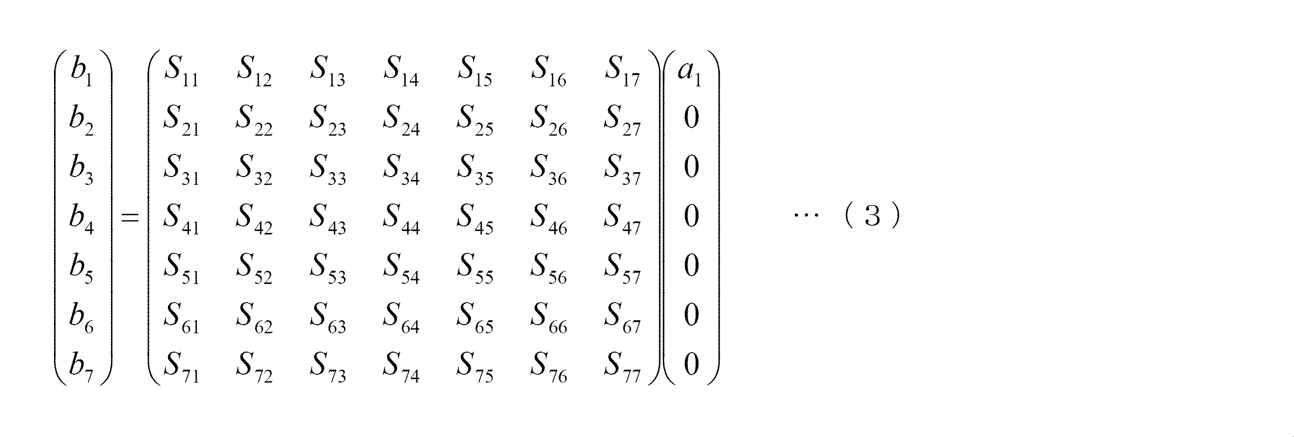
- the S parameter S i1 representing the relationship between the incident microwave introduced into the processing container 2 from the first microwave introduction module 611 and the reflected microwave reflected by the i-th microwave introduction module 61 i is obtained. Will be explained.
- the introduction of microwaves from the second to seventh microwave introduction modules 612 to 617 is stopped.
- the relationship between the incident microwave and the reflected microwave is expressed by the following equation (3).
- the incident microwave is introduced into the processing container 2 by the first microwave introduction module 611, and the power value of the incident microwave is measured by the power measuring device 62E of the first microwave introduction module 611.
- the power values of the reflected microwaves are measured by the respective power measuring devices 62E of the first to seventh microwave introduction modules 611 to 617.
- the power value of the incident microwave and the power value of the reflected microwave satisfy the relationship represented by the following formula (4).
- the incident microwave introduced by the first microwave introduction module 611 includes a plurality of incident waves having different power values.
- the incident microwave may include five incident waves having different power values by 1 W within a range of 1 W to 5 W.
- the reflected microwave includes a plurality of reflected waves that respectively correspond to a plurality of incident waves. Then,
- the acquisition method of ij (j ⁇ 1) is the same as the acquisition method of the S parameter S i1 described above. That is, by introducing incident microwaves for each of the second to seventh microwave introduction modules 612 to 617 and measuring the reflected microwaves reflected by the first to seventh microwave introduction modules 611 to 617, The S parameter S ij can be determined.
- the S parameter S ij relating to two combinations selected from among the plurality of microwave introduction modules 61 may be acquired so as to cover all the two combinations selected from among the plurality of microwave introduction modules 61. You may acquire about a specific combination. Specific combinations include, for example, a combination of the first microwave introduction module 611 and the second to seventh microwave introduction modules 612 to 617, or between the second to seventh microwave introduction modules 612 to 617. There are combinations. Examples of combinations between the second to seventh microwave introduction modules 612 to 617 include first to third combinations described below.
- FIG. 8 is an explanatory diagram showing the first combination.
- the first combination is a combination of two microwave introduction modules 61 that are adjacent along the outer periphery of the above-mentioned virtual regular hexagon.
- a combination of two adjacent microwave introduction modules 61 is indicated by a two-dot chain line.
- FIG. 9 is an explanatory diagram showing the second combination.
- the second combination is a combination of two microwave introduction modules 61 that are adjacent to each other along the outer circumference of the virtual regular hexagon.
- a combination of two microwave introduction modules 61 adjacent to each other is indicated by a two-dot chain line.
- FIG. 10 is an explanatory diagram showing the third combination.
- the third combination is a combination of two microwave introduction modules 61 that are adjacent to each other along the outer periphery of the virtual regular hexagon.
- a combination of two microwave introduction modules 61 adjacent to every other two is indicated by a two-dot chain line.
- an abnormality in the plurality of microwave introduction modules 61 is detected using the S parameter S ij acquired as described above.
- This abnormality detection can be performed at any time after the use of the plasma processing apparatus 1 is started. For example, this abnormality detection may be performed before processing a product of a specific lot.
- the absolute value of the difference includes ⁇ S 1 , ⁇ S 2 , ⁇ S 3 , ⁇ S 4 , ⁇ S 5 , and ⁇ S 6 defined by the following formula (5).
- Expression (5) is derived based on Expression (2). Therefore, ideally, ⁇ S 1 to ⁇ S 6 are all zero. However, if any abnormality occurs in the microwave introduction module 61, ⁇ S 1 to ⁇ S 6 become larger than zero. Examples of the abnormality in the microwave introduction module 61 include a failure of the amplifier unit 62, the tuner 64, and the antenna unit 65.
- [Delta] S 4 represents the absolute value of the difference S-parameters S ij between the first combination of the foregoing
- [Delta] S 5 represents the absolute value of the difference S-parameters S ij between the second combination of the foregoing
- ⁇ S 6 represents the absolute value of the difference between the S parameters S ij of the third combination described above.
- each maximum value of ⁇ S 1 to ⁇ S 6 is obtained.
- the maximum values of ⁇ S 1 to ⁇ S 6 are referred to as ⁇ S 1max to ⁇ S 6max .
- a maximum value ⁇ S max is calculated from ⁇ S 1max to ⁇ S 6max .
- ⁇ S max is compared with a predetermined threshold value representing an abnormality in the plurality of microwave introduction modules 61.
- ⁇ S max when ⁇ S max is smaller than a predetermined threshold value, it is determined that all the microwave introduction modules 61 are normal. When ⁇ S max is equal to or greater than a predetermined threshold value, it is determined that any of the plurality of microwave introduction modules 61 is abnormal.
- the threshold value can be set to a predetermined value with reference to the S parameter in a normal state of the microwave introduction module 61 and the S parameter in a state where an abnormality has occurred, for example, 0.07. be able to.
- the microwave introduction module 61 in which an abnormality has occurred can be identified, for example, by examining which combination of the plurality of microwave introduction modules 61 has obtained ⁇ S max .
- the microwave introduction module 61 in which an abnormality has been detected is removed from the plasma processing apparatus 1 and replaced with a normal microwave introduction module 61. Thereby, it becomes possible to use the plasma processing apparatus 1 normally.
- the microwave introduction module 61 removed from the plasma processing apparatus 1 is checked for various operations, and repairs such as component replacement are performed according to the results. As a result, the microwave introduction module 61 can be used as a normal microwave introduction module 61.
- FIG. 11 is a flowchart illustrating an example of the procedure of the abnormality detection method.
- FIG. 12 is a flowchart illustrating an example of a procedure of an S parameter acquisition method.
- the S parameter S ij is acquired.
- the inside of the processing vessel 2 is in a vacuum state and a state in which plasma is not generated.
- an incident microwave is introduced by the first microwave introduction module 611.
- the reflected microwaves are measured in the first to seventh microwave introduction modules 611 to 617.
- S parameters S 11 to S 71 are obtained.
- the step of obtaining the S parameter from the step of introducing the incident microwave is sequentially executed from the second microwave introduction module 612 to the seventh microwave introduction module 617.
- the above arithmetic processing can be performed by, for example, the process controller 81 of the control unit 8.
- ⁇ S 1 to ⁇ S 6 are obtained as shown in FIG.
- ⁇ S 1max to ⁇ S 6max are obtained.
- ⁇ S max is obtained.
- ⁇ S max is compared with a predetermined threshold value representing an abnormality in the plurality of microwave introduction modules 61.
- the above arithmetic processing can be performed by, for example, the process controller 81 of the control unit 8.
- ⁇ S max is smaller than the predetermined threshold value, it can be confirmed that all the microwave introduction modules 61 are in a normal state. Therefore, the process controller 81 controls the control signal to execute the predetermined plasma processing. And plasma processing is executed in the processing container 2.
- ⁇ S max is equal to or greater than a predetermined threshold
- an abnormality in the microwave introduction module 61 is detected.
- the microwave introduction module 61 in which an abnormality has occurred is identified. In this case, for example, the fact that an abnormality has been detected and the information of the microwave introduction module 61 in which the abnormality has been detected can be displayed on the display of the user interface 82 of the control unit 8.
- the procedure so far can be automatically executed by the process controller 81 of the control unit 8 based on, for example, an abnormality detection recipe.
- the microwave introduction module 61 in which the abnormality is detected is replaced with a normal microwave introduction module 61.
- the abnormality detection method according to the present embodiment is executed again.
- an incident microwave is introduced into each of the plurality of microwave introduction modules 61 (611 to 617), and a plurality of incident microwaves and a plurality of components from the processing container 2 are introduced.
- the S parameter S ij for every two combinations selected from among the plurality of microwave introduction modules 61 is obtained.
- the absolute value of the S parameter S ij of any two combinations selected from the plurality of microwave introduction modules 61 and the other two microwave introductions having different combinations are introduced.
- a difference from the absolute value of the S parameter S ij of the module 61 is obtained, and a maximum value of the absolute value of the difference is compared with a predetermined threshold value representing an abnormality in the plurality of microwave introduction modules 61. From these things, according to this Embodiment, the abnormality in the microwave introduction module 61 can be detected.
- the abnormality in the microwave introduction module 61 may be detected by directly comparing each of ⁇ S 1 to ⁇ S 6 which is the absolute value of the difference between the S parameters S ij with a predetermined threshold value. Further, the difference itself may be compared with the threshold value regardless of the absolute values ⁇ S 1 to ⁇ S 6 of the differences between the S parameters S ij depending on how the threshold value is set. Further, as long as the requirements of the claims are satisfied, the number and arrangement of the microwave introduction modules 61 are not limited to the example shown in the embodiment, and are arbitrary.
Landscapes
- Physics & Mathematics (AREA)
- Engineering & Computer Science (AREA)
- Plasma & Fusion (AREA)
- Chemical & Material Sciences (AREA)
- Analytical Chemistry (AREA)
- Electromagnetism (AREA)
- Spectroscopy & Molecular Physics (AREA)
- General Physics & Mathematics (AREA)
- Plasma Technology (AREA)
- Drying Of Semiconductors (AREA)
Abstract
Description
以下、本発明の実施の形態について図面を参照して詳細に説明する。始めに、図1及び図2を参照して、本発明の一実施の形態に係るSパラメータの取得方法及び異常検知方法が適用されるプラズマ処理装置の概略の構成について説明する。図1は、本実施の形態におけるプラズマ処理装置の概略の構成を示す断面図である。図2は、図1に示した制御部の構成を示す説明図である。本実施の形態におけるプラズマ処理装置1は、連続する複数の動作を伴って、例えば半導体デバイス製造用の半導体ウエハ(以下、単に「ウエハ」と記す。)Wに対して、成膜処理、拡散処理、エッチング処理、アッシング処理等の所定の処理を施す装置である。 [Plasma processing equipment]
Hereinafter, embodiments of the present invention will be described in detail with reference to the drawings. First, a schematic configuration of a plasma processing apparatus to which an S parameter acquisition method and an abnormality detection method according to an embodiment of the present invention are applied will be described with reference to FIGS. 1 and 2. FIG. 1 is a cross-sectional view showing a schematic configuration of a plasma processing apparatus in the present embodiment. FIG. 2 is an explanatory diagram illustrating a configuration of the control unit illustrated in FIG. 1. The
処理容器2は、例えば略円筒形状をなしている。処理容器2は、例えばアルミニウム及びその合金等の金属材料によって形成されている。マイクロ波導入装置5は、処理容器2の上部に設けられ、処理容器2内に電磁波(マイクロ波)を導入してプラズマを生成するプラズマ生成手段として機能する。マイクロ波導入装置5の構成については、後で詳しく説明する。 <Processing container>
The
底部13は、複数(図1では2つ)の排気口13aを有している。プラズマ処理装置1は、更に、排気口13aと排気装置4とを接続する排気管14を備えている。排気装置4は、APCバルブと、処理容器2の内部空間を所定の真空度まで高速に減圧することが可能な高速真空ポンプとを有している。このような高速真空ポンプとしては、例えばターボ分子ポンプ等がある。排気装置4の高速真空ポンプを作動させることによって、処理容器2は、その内部空間が所定の真空度、例えば0.133Paまで減圧される。 <Exhaust device>
The
プラズマ処理装置1は、更に、処理容器2内において載置台21を支持する支持部材22と、支持部材22と処理容器2の底部13との間に設けられた絶縁材料よりなる絶縁部材23とを備えている。載置台21は、被処理体であるウエハWを水平に載置するためのものである。支持部材22は、底部13の中央から処理容器2の内部空間に向かって延びる円筒状の形状を有している。載置台21及び支持部材22は、例えば表面にアルマイト処理(陽極酸化処理)が施されたアルミニウム等によって形成されている。 <Mounting table>
The
プラズマ処理装置1は、更に、載置台21に高周波電力を供給する高周波バイアス電源25と、載置台21と高周波バイアス電源25との間に設けられた整合器24とを備えている。高周波バイアス電源25は、ウエハWにイオンを引き込むために、載置台21に高周波電力を供給する。 <High frequency bias power supply>
The
図示しないが、プラズマ処理装置1は、更に、載置台21を加熱又は冷却する温度制御機構を備えている。温度制御機構は、例えば、ウエハWの温度を、25℃(室温)~900℃の範囲内で制御する。 <Temperature control mechanism>
Although not shown, the
プラズマ処理装置1は、更に、処理容器2の天井部11に設けられたガス導入部15を備えている。ガス導入部15は、円筒形状をなす複数のノズル16を有している。ノズル16は、その下面に形成されたガス孔16aを有している。 <Gas supply mechanism>
The
プラズマ処理装置1の各構成部は、それぞれ制御部8に接続されて、制御部8によって制御される。制御部8は、典型的にはコンピュータである。図2に示した例では、制御部8は、CPUを備えたプロセスコントローラ81と、このプロセスコントローラ81に接続されたユーザーインターフェース82及び記憶部83とを備えている。 <Control unit>
Each component of the
次に、図1、図3ないし図6を参照して、マイクロ波導入装置5の構成について詳しく説明する。図3は、マイクロ波導入装置5の構成を示す説明図である。図4は、マイクロ波導入モジュール61の一部を示す断面図である。図5は、マイクロ波導入モジュール61のアンテナ部を示す斜視図である。図6は、マイクロ波導入モジュール61の平面アンテナを示す平面図である。図1及び図3に示したように、マイクロ波導入装置5は、マイクロ波を生成すると共に、このマイクロ波を複数の経路に分配して出力するマイクロ波出力部50と、マイクロ波出力部50によって分配されたマイクロ波を、処理容器2内の別々の場所に導入する複数のマイクロ波導入モジュール61とを有している。 [Microwave introduction device]
Next, the configuration of the
マイクロ波出力部50は、電源部51と、マイクロ波発振器52と、マイクロ波発振器52によって発振されたマイクロ波を増幅するアンプ53と、アンプ53によって増幅されたマイクロ波を複数の経路に分配する分配器54とを有している。マイクロ波発振器52は、所定の周波数(例えば、2.45GHz)でマイクロ波を発振(例えば、PLL発振)させる。なお、マイクロ波の周波数は、2.45GHzに限らず、8.35GHz、5.8GHz、1.98GHz等であってもよい。また、このようなマイクロ波出力部50は、マイクロ波の周波数を800MHzから1GHzの範囲内とする場合にも適用することが可能である。分配器54は、入力側と出力側のインピーダンスを整合させながらマイクロ波を分配する。 <Microwave output section>
The
複数のマイクロ波導入モジュール61は、それぞれ、互いに異なる位置に配置され、分配器54によって分配されたマイクロ波を、処理容器2内の別々の場所に導入する。本実施の形態では、複数のマイクロ波導入モジュール61の構成は全て同一である。各マイクロ波導入モジュール61は、分配されたマイクロ波を主に増幅して出力するアンプ部62と、アンプ部62から出力されたマイクロ波を処理容器2内に導入するマイクロ波導入部63とを有している。 <Microwave introduction module>
The plurality of
アンプ部62は、マイクロ波の位相を変化させる位相器62Aと、メインアンプ62Cに入力されるマイクロ波の電力レベルを調整する可変ゲインアンプ62Bと、ソリッドステートアンプとして構成されたメインアンプ62Cと、後述するマイクロ波導入部63のアンテナ部で反射されてメインアンプ62Cに向かうマイクロ波を分離するアイソレータ62Dと、処理容器2内に導入されるマイクロ波及び処理容器2で反射された反射マイクロ波の電力値(パワー)を測定する電力測定器62Eとを含んでいる。 (Amplifier part)
The
図1に示したように、複数のマイクロ波導入部63は、天井部11に設けられている。図4に示したように、マイクロ波導入部63は、インピーダンスを整合させるチューナ64と、増幅されたマイクロ波を処理容器2内に放射するアンテナ部65と、金属材料よりなり、同軸管を構成する本体容器66及び内部導体67とを有している。本体容器66は、図4における上下方向に延びる円筒状の形状を有し、同軸管の外側導体を構成している。内側導体67は、図4における上下方向に延びる棒状又は筒状の形状を有している。本体容器66の内周面と内側導体67の外周面との間の空間は、マイクロ波伝送路68を形成する。 (Microwave introduction part)
As shown in FIG. 1, the plurality of
次に、図7を参照して、天井部11における複数のマイクロ波導入ポート11aの配置について説明する。図7は、処理容器2の天井部11の底面を示す平面図である。なお、図7では、本体容器66の図示を省略している。 [Microwave introduction port]
Next, the arrangement of the plurality of
次に、プラズマ処理装置1におけるプラズマ処理の一例について説明する。ここでは、処理ガスとして窒素を含有するガスを使用して、ウエハWの表面に対してプラズマ窒化処理を施す場合を例に挙げて、プラズマ処理の手順について説明する。まず、例えばユーザーインターフェース82から、プラズマ処理装置1においてプラズマ窒化処理を行うように、プロセスコントローラ81に指令が入力される。次に、プロセスコントローラ81は、この指令を受けて、記憶部83又はコンピュータ読み取り可能な記憶媒体に保存されたレシピを読み出す。次に、レシピに基づく条件によってプラズマ窒化処理が実行されるように、プロセスコントローラ81からプラズマ処理装置1の各エンドデバイス(例えば、高周波バイアス電源25、ガス供給装置3a、排気装置4、マイクロ波導入装置5等)に制御信号が送出される。 [Processing procedure]
Next, an example of plasma processing in the
次に、本実施の形態に係るSパラメータの取得方法について説明する。ここでは、マイクロ波導入装置5が前述の第1ないし第7のマイクロ波導入モジュール611~617を有する場合を例にとって説明する。 [S parameter acquisition method]
Next, an S parameter acquisition method according to the present embodiment will be described. Here, a case where the


次に、本実施の形態に係る異常検知方法について説明する。本実施の形態では、上述のようにして取得されたSパラメータSijを用いて、複数のマイクロ波導入モジュール61における異常を検知している。なお、この異常検知は、プラズマ処理装置1の使用開始後、任意の時期に行うことができる。例えば、特定のロットの製品を処理する前に、この異常検知を実行してもよい。 [Abnormality detection method]
Next, the abnormality detection method according to the present embodiment will be described. In the present embodiment, an abnormality in the plurality of

This international application claims priority based on Japanese Patent Application No. 2012-153902 filed on July 9, 2012, the entire contents of which are incorporated herein by reference.
Claims (12)
- 被処理体を収容する処理容器と、
前記処理容器内においてプラズマを生成させるためのマイクロ波を前記処理容器内に導入する複数のマイクロ波導入モジュールを有するマイクロ波導入装置と、
前記処理容器内を減圧排気する排気装置と、
を備えたプラズマ処理装置において前記マイクロ波導入モジュールのSパラメータを取得する方法であって、
前記複数のマイクロ波導入モジュールは、それぞれ、前記マイクロ波を前記処理容器内の別々の場所に導入するものであり、
前記処理容器内を、真空状態、且つ、前記プラズマが生成されない状態にして、前記複数のマイクロ波導入モジュール毎に前記マイクロ波を導入し、このマイクロ波と、前記処理容器から前記複数のマイクロ波導入モジュールに反射された反射マイクロ波に基づいて、前記複数のマイクロ波導入モジュールの中から選ばれる2つの組み合わせ毎のSパラメータを求めることを特徴とするSパラメータの取得方法。 A processing container for storing an object to be processed;
A microwave introduction device having a plurality of microwave introduction modules for introducing microwaves for generating plasma in the processing vessel into the processing vessel;
An exhaust device for evacuating the inside of the processing vessel;
A method for obtaining S parameters of the microwave introduction module in a plasma processing apparatus comprising:
Each of the plurality of microwave introduction modules introduces the microwaves to different places in the processing container,
The inside of the processing container is in a vacuum state and the plasma is not generated, and the microwave is introduced into each of the plurality of microwave introduction modules, and the microwave and the plurality of microwaves from the processing container are introduced. A method for obtaining an S parameter, wherein an S parameter for each of two combinations selected from the plurality of microwave introduction modules is obtained based on the reflected microwave reflected by the introduction module. - 前記複数のマイクロ波導入モジュールは、それぞれ、前記マイクロ波及び前記反射マイクロ波の電力値を測定する電力測定器を有し、
前記複数のマイクロ波導入モジュールの中から選ばれる2つの組み合わせ毎のSパラメータは、前記マイクロ波及び前記反射マイクロ波の電力値を用いて求められるものであることを特徴とする請求項1に記載のSパラメータの取得方法。 Each of the plurality of microwave introduction modules has a power measuring device for measuring power values of the microwave and the reflected microwave,
The S parameter for each of two combinations selected from the plurality of microwave introduction modules is obtained using the power values of the microwave and the reflected microwave. Of obtaining S-parameters. - 前記マイクロ波は、前記複数のマイクロ波導入モジュール毎に電力値の異なる複数の入射波を含み、
前記反射マイクロ波は、それぞれ前記複数の入射波に対応する複数の反射波を含むことを特徴とする請求項2に記載のSパラメータの取得方法。 The microwave includes a plurality of incident waves having different power values for the plurality of microwave introduction modules,
The S-parameter acquisition method according to claim 2, wherein the reflected microwave includes a plurality of reflected waves respectively corresponding to the plurality of incident waves. - 前記複数のマイクロ波導入モジュールの中から選ばれる2つの組み合わせ毎のSパラメータは、前記複数の入射波の電力値と前記複数の反射波の電力値から、最小二乗法によって求められるものであることを特徴とする請求項3に記載のSパラメータの取得方法。 The S parameter for each of the two combinations selected from the plurality of microwave introduction modules is obtained by the least square method from the power values of the plurality of incident waves and the power values of the plurality of reflected waves. The method for acquiring an S parameter according to claim 3.
- 前記マイクロ波導入装置は、前記複数のマイクロ波導入モジュールとして、第1ないし第7のマイクロ波導入モジュールを有し、
前記処理容器は、それぞれ前記第1ないし第7のマイクロ波導入モジュールによって導入される前記マイクロ波を前記処理容器内に通過させる第1ないし第7のマイクロ波導入ポートを有する天井部を含み、
前記第1のマイクロ波導入ポートは、前記天井部の中央部分に配置され、
前記第2ないし第7のマイクロ波導入ポートは、それぞれ、前記天井部において、前記第1のマイクロ波導入ポートを中心とする仮想の正六角形の頂点に配置されることを特徴とする請求項1に記載のSパラメータの取得方法。 The microwave introduction device has first to seventh microwave introduction modules as the plurality of microwave introduction modules,
The processing container includes a ceiling portion having first to seventh microwave introduction ports for allowing the microwaves introduced by the first to seventh microwave introduction modules to pass through the processing container, respectively.
The first microwave introduction port is disposed in a central portion of the ceiling;
2. The second to seventh microwave introduction ports are respectively arranged at vertices of virtual regular hexagons centering on the first microwave introduction port in the ceiling portion. The acquisition method of S parameter as described in 1 .. - 前記複数のマイクロ波導入モジュールの中から選ばれる2つの組み合わせは、前記第1のマイクロ波導入モジュールと前記第2ないし第7のいずれかのマイクロ波導入モジュールとの組み合わせを含むことを特徴とする請求項5に記載のSパラメータの取得方法。 Two combinations selected from the plurality of microwave introduction modules include a combination of the first microwave introduction module and any one of the second to seventh microwave introduction modules. The method for obtaining an S parameter according to claim 5.
- 前記複数のマイクロ波導入モジュールの中から選ばれる2つの組み合わせは、前記仮想の正六角形の外周に沿って隣接する2つのマイクロ波導入モジュールを組み合わせる第1の組み合わせと、前記仮想の正六角形の外周に沿って1つおきに隣接する2つのマイクロ波導入モジュールを組み合わせる第2の組み合わせと、前記仮想の正六角形の外周に沿って2つおきに隣接する2つのマイクロ波導入モジュールを組み合わせる第3の組み合わせのうち、少なくとも1つを含むことを特徴とする請求項5に記載のSパラメータの取得方法。 Two combinations selected from among the plurality of microwave introduction modules include a first combination that combines two microwave introduction modules adjacent along the outer periphery of the virtual regular hexagon, and an outer periphery of the virtual regular hexagon. A second combination that combines two microwave introduction modules that are adjacent to each other along the outer circumference of the virtual regular hexagon, and a third combination that combines two microwave introduction modules that are adjacent to each other along the outer circumference of the virtual regular hexagon. 6. The method for acquiring an S parameter according to claim 5, wherein at least one of the combinations is included.
- 前記複数のマイクロ波導入モジュールの中から選ばれる2つの組み合わせは、前記第1ないし第7のマイクロ波導入モジュールの全てを網羅する組み合わせであることを特徴とする請求項5に記載のSパラメータの取得方法。 6. The S parameter according to claim 5, wherein the two combinations selected from the plurality of microwave introduction modules are combinations that cover all of the first to seventh microwave introduction modules. Acquisition method.
- 被処理体を収容する処理容器と、
前記処理容器内においてプラズマを生成させるためのマイクロ波を前記処理容器内に導入する複数のマイクロ波導入モジュールを有するマイクロ波導入装置と、
前記処理容器内を減圧排気する排気装置と、
を備えたプラズマ処理装置において、前記マイクロ波導入モジュールにおける異常を検知する方法であって、
前記複数のマイクロ波導入モジュールは、それぞれ、前記マイクロ波を前記処理容器内の別々の場所に導入するものであり、
請求項1から8のいずれか1項に記載のSパラメータの取得方法によって取得された、複数のSパラメータの絶対値の間で差分を求め、この差分に基づき前記異常を検知することを特徴とする異常検知方法。 A processing container for storing an object to be processed;
A microwave introduction device having a plurality of microwave introduction modules for introducing microwaves for generating plasma in the processing vessel into the processing vessel;
An exhaust device for evacuating the inside of the processing vessel;
In the plasma processing apparatus comprising: a method for detecting an abnormality in the microwave introduction module,
Each of the plurality of microwave introduction modules introduces the microwaves to different places in the processing container,
A difference between absolute values of a plurality of S parameters acquired by the S parameter acquisition method according to claim 1 is obtained, and the abnormality is detected based on the difference. Anomaly detection method to do. - 前記差分の絶対値を、前記複数のマイクロ波導入モジュールにおける異常を表す所定のしきい値と比較することを特徴とする請求項9に記載の異常検知方法。 10. The abnormality detection method according to claim 9, wherein the absolute value of the difference is compared with a predetermined threshold value representing an abnormality in the plurality of microwave introduction modules.
- 前記差分は、取得された複数のSパラメータのすべてについて相互に演算して得られた複数の差分であることを特徴とする請求項10に記載の異常検知方法。 The abnormality detection method according to claim 10, wherein the difference is a plurality of differences obtained by mutually calculating all of the plurality of acquired S parameters.
- 前記複数の差分の絶対値の最大値と、前記しきい値とを比較することを特徴とする請求項11に記載の異常検知方法。
The abnormality detection method according to claim 11, wherein a maximum absolute value of the plurality of differences is compared with the threshold value.
Priority Applications (4)
| Application Number | Priority Date | Filing Date | Title |
|---|---|---|---|
| US14/413,170 US9702913B2 (en) | 2012-07-09 | 2013-06-11 | Acquisition method for S-parameters in microwave introduction modules, and malfunction detection method |
| CN201380036701.4A CN104472020B (en) | 2012-07-09 | 2013-06-11 | The S parameter adquisitiones and method for detecting abnormality that microwave is imported in component |
| KR1020177018571A KR101856430B1 (en) | 2012-07-09 | 2013-06-11 | Malfunction detection method in microwave introduction modules |
| KR1020157000359A KR101759406B1 (en) | 2012-07-09 | 2013-06-11 | Acquisition method for s-parameters in microwave introduction modules, and malfunction detection method |
Applications Claiming Priority (2)
| Application Number | Priority Date | Filing Date | Title |
|---|---|---|---|
| JP2012-153902 | 2012-07-09 | ||
| JP2012153902A JP6037688B2 (en) | 2012-07-09 | 2012-07-09 | Anomaly detection method in microwave introduction module |
Publications (1)
| Publication Number | Publication Date |
|---|---|
| WO2014010356A1 true WO2014010356A1 (en) | 2014-01-16 |
Family
ID=49915824
Family Applications (1)
| Application Number | Title | Priority Date | Filing Date |
|---|---|---|---|
| PCT/JP2013/066016 WO2014010356A1 (en) | 2012-07-09 | 2013-06-11 | Acquisition method for s-parameters in microwave introduction modules, and malfunction detection method |
Country Status (5)
| Country | Link |
|---|---|
| US (1) | US9702913B2 (en) |
| JP (1) | JP6037688B2 (en) |
| KR (2) | KR101856430B1 (en) |
| CN (1) | CN104472020B (en) |
| WO (1) | WO2014010356A1 (en) |
Cited By (1)
| Publication number | Priority date | Publication date | Assignee | Title |
|---|---|---|---|---|
| CN104316785A (en) * | 2014-10-08 | 2015-01-28 | 中国电子科技集团公司第四十一研究所 | Antenna feeder tester and extending device error correction method |
Families Citing this family (11)
| Publication number | Priority date | Publication date | Assignee | Title |
|---|---|---|---|---|
| KR102069558B1 (en) * | 2014-01-24 | 2020-01-23 | 한국전자통신연구원 | Plasma antenna |
| JP6479562B2 (en) * | 2015-05-07 | 2019-03-06 | 東京エレクトロン株式会社 | Method of generating processing condition of plasma processing apparatus and plasma processing apparatus |
| CN105510738B (en) * | 2015-11-27 | 2019-01-01 | 电子科技大学 | Microwave high power device Nonlinear thermal system for automatically testing parameters and its test method |
| JP6704275B2 (en) * | 2016-03-28 | 2020-06-03 | 株式会社ディスコ | Device wafer evaluation method |
| US10748745B2 (en) * | 2016-08-16 | 2020-08-18 | Applied Materials, Inc. | Modular microwave plasma source |
| CN106680684B (en) * | 2017-03-24 | 2023-06-02 | 中国工程物理研究院应用电子学研究所 | Measuring device and method for high-frequency system of folded waveguide traveling wave tube |
| JP6960813B2 (en) * | 2017-09-20 | 2021-11-05 | 東京エレクトロン株式会社 | Graphene structure forming method and forming device |
| JP2021042409A (en) * | 2019-09-09 | 2021-03-18 | 東京エレクトロン株式会社 | Plasma treatment apparatus and temperature control method |
| CN110954818B (en) * | 2019-12-13 | 2022-08-09 | 哈尔滨工业大学 | Intermediate relay coil soft fault detection method |
| CN111578851B (en) * | 2020-05-12 | 2021-08-17 | 晶澳太阳能有限公司 | Method for testing plate type PECVD microwave capability |
| JP2022150627A (en) * | 2021-03-26 | 2022-10-07 | 東京エレクトロン株式会社 | Plasma processing device and plasma processing method |
Citations (4)
| Publication number | Priority date | Publication date | Assignee | Title |
|---|---|---|---|---|
| JP2005158684A (en) * | 2003-10-29 | 2005-06-16 | Sumihide Ikenouchi | Plasma processing device, evaluation method and control method of the same |
| JP2009099496A (en) * | 2007-10-19 | 2009-05-07 | Hitachi High-Technologies Corp | Plasma treatment device, and method of detecting its condition |
| JP2009230915A (en) * | 2008-03-19 | 2009-10-08 | Tokyo Electron Ltd | Power combiner and microwave introduction mechanism |
| JP2011202973A (en) * | 2010-03-24 | 2011-10-13 | Daihen Corp | High-frequency measuring device, and method for calibrating high-frequency measuring device |
Family Cites Families (9)
| Publication number | Priority date | Publication date | Assignee | Title |
|---|---|---|---|---|
| JP2002305182A (en) * | 2001-04-06 | 2002-10-18 | Matsushita Electric Ind Co Ltd | Method and apparatus for plasma processing |
| JP2003197609A (en) * | 2001-12-27 | 2003-07-11 | Tokyo Electron Ltd | Method for monitoring plasma treatment device, and plasma treatment device |
| JP4071077B2 (en) * | 2002-09-26 | 2008-04-02 | 株式会社ダイヘン | Method and apparatus for monitoring plasma processing apparatus |
| JP4694130B2 (en) * | 2004-01-19 | 2011-06-08 | 東京エレクトロン株式会社 | Plasma processing equipment |
| CN1292624C (en) * | 2004-09-23 | 2006-12-27 | 烽火通信科技股份有限公司 | Dynamic design method and device for plasma resonant chamber |
| US7061254B1 (en) | 2005-05-12 | 2006-06-13 | Agilent Technologies, Inc. | Power calibration for multi-port vector network analyzer (VNA) |
| JP4777717B2 (en) * | 2005-08-10 | 2011-09-21 | 東京エレクトロン株式会社 | Film forming method, plasma processing apparatus, and recording medium |
| JP5376816B2 (en) * | 2008-03-14 | 2013-12-25 | 東京エレクトロン株式会社 | Microwave introduction mechanism, microwave plasma source, and microwave plasma processing apparatus |
| JP2012089334A (en) | 2010-10-19 | 2012-05-10 | Tokyo Electron Ltd | Microwave plasma source and plasma processing apparatus |
-
2012
- 2012-07-09 JP JP2012153902A patent/JP6037688B2/en active Active
-
2013
- 2013-06-11 KR KR1020177018571A patent/KR101856430B1/en active IP Right Grant
- 2013-06-11 WO PCT/JP2013/066016 patent/WO2014010356A1/en active Application Filing
- 2013-06-11 CN CN201380036701.4A patent/CN104472020B/en active Active
- 2013-06-11 US US14/413,170 patent/US9702913B2/en active Active
- 2013-06-11 KR KR1020157000359A patent/KR101759406B1/en active IP Right Grant
Patent Citations (4)
| Publication number | Priority date | Publication date | Assignee | Title |
|---|---|---|---|---|
| JP2005158684A (en) * | 2003-10-29 | 2005-06-16 | Sumihide Ikenouchi | Plasma processing device, evaluation method and control method of the same |
| JP2009099496A (en) * | 2007-10-19 | 2009-05-07 | Hitachi High-Technologies Corp | Plasma treatment device, and method of detecting its condition |
| JP2009230915A (en) * | 2008-03-19 | 2009-10-08 | Tokyo Electron Ltd | Power combiner and microwave introduction mechanism |
| JP2011202973A (en) * | 2010-03-24 | 2011-10-13 | Daihen Corp | High-frequency measuring device, and method for calibrating high-frequency measuring device |
Cited By (2)
| Publication number | Priority date | Publication date | Assignee | Title |
|---|---|---|---|---|
| CN104316785A (en) * | 2014-10-08 | 2015-01-28 | 中国电子科技集团公司第四十一研究所 | Antenna feeder tester and extending device error correction method |
| CN104316785B (en) * | 2014-10-08 | 2017-03-01 | 中国电子科技集团公司第四十一研究所 | A kind of antenna feeder tester and extension device error correcting method |
Also Published As
| Publication number | Publication date |
|---|---|
| US9702913B2 (en) | 2017-07-11 |
| JP2014017121A (en) | 2014-01-30 |
| KR101856430B1 (en) | 2018-05-09 |
| KR101759406B1 (en) | 2017-07-18 |
| KR20170082662A (en) | 2017-07-14 |
| JP6037688B2 (en) | 2016-12-07 |
| CN104472020B (en) | 2018-01-09 |
| KR20150040846A (en) | 2015-04-15 |
| US20150212127A1 (en) | 2015-07-30 |
| CN104472020A (en) | 2015-03-25 |
Similar Documents
| Publication | Publication Date | Title |
|---|---|---|
| JP6037688B2 (en) | Anomaly detection method in microwave introduction module | |
| JP5893865B2 (en) | Plasma processing apparatus and microwave introduction apparatus | |
| KR101475591B1 (en) | Plasma processing apparatus and plasma monitoring method | |
| KR100960424B1 (en) | Microwave plasma processing device | |
| WO2013027470A1 (en) | Plasma processor, microwave introduction device, and plasma processing method | |
| WO2021157445A1 (en) | Plasma treatment apparatus and gas flow-rate control method | |
| US20170263421A1 (en) | Plasma Processing Apparatus and Plasma Processing Method | |
| US20130022760A1 (en) | Plasma nitriding method | |
| JP5953057B2 (en) | Plasma processing method and plasma processing apparatus | |
| US20210110999A1 (en) | Plasma processing apparatus | |
| JP5479013B2 (en) | Plasma processing apparatus and slow wave plate used therefor | |
| US10777389B2 (en) | Plasma processing apparatus and plasma processing method | |
| WO2011013633A1 (en) | Planar antenna member and plasma processing device equipped with same | |
| WO2009113680A1 (en) | Flat antenna member and a plasma processing device provided with same | |
| US20230343561A1 (en) | Plasma processing apparatus and ceiling wall | |
| JP5728565B2 (en) | Plasma processing apparatus and slow wave plate used therefor |
Legal Events
| Date | Code | Title | Description |
|---|---|---|---|
| 121 | Ep: the epo has been informed by wipo that ep was designated in this application |
Ref document number: 13816152 Country of ref document: EP Kind code of ref document: A1 |
|
| WWE | Wipo information: entry into national phase |
Ref document number: 14413170 Country of ref document: US |
|
| ENP | Entry into the national phase |
Ref document number: 20157000359 Country of ref document: KR Kind code of ref document: A |
|
| NENP | Non-entry into the national phase |
Ref country code: DE |
|
| 122 | Ep: pct application non-entry in european phase |
Ref document number: 13816152 Country of ref document: EP Kind code of ref document: A1 |