WO2014007373A1 - エンジン装置 - Google Patents
エンジン装置 Download PDFInfo
- Publication number
- WO2014007373A1 WO2014007373A1 PCT/JP2013/068519 JP2013068519W WO2014007373A1 WO 2014007373 A1 WO2014007373 A1 WO 2014007373A1 JP 2013068519 W JP2013068519 W JP 2013068519W WO 2014007373 A1 WO2014007373 A1 WO 2014007373A1
- Authority
- WO
- WIPO (PCT)
- Prior art keywords
- engine
- exhaust
- bracket
- exhaust gas
- side bracket
- Prior art date
Links
Images


Classifications
-
- F—MECHANICAL ENGINEERING; LIGHTING; HEATING; WEAPONS; BLASTING
- F02—COMBUSTION ENGINES; HOT-GAS OR COMBUSTION-PRODUCT ENGINE PLANTS
- F02B—INTERNAL-COMBUSTION PISTON ENGINES; COMBUSTION ENGINES IN GENERAL
- F02B75/00—Other engines
- F02B75/06—Engines with means for equalising torque
-
- F—MECHANICAL ENGINEERING; LIGHTING; HEATING; WEAPONS; BLASTING
- F01—MACHINES OR ENGINES IN GENERAL; ENGINE PLANTS IN GENERAL; STEAM ENGINES
- F01N—GAS-FLOW SILENCERS OR EXHAUST APPARATUS FOR MACHINES OR ENGINES IN GENERAL; GAS-FLOW SILENCERS OR EXHAUST APPARATUS FOR INTERNAL COMBUSTION ENGINES
- F01N13/00—Exhaust or silencing apparatus characterised by constructional features ; Exhaust or silencing apparatus, or parts thereof, having pertinent characteristics not provided for in, or of interest apart from, groups F01N1/00 - F01N5/00, F01N9/00, F01N11/00
- F01N13/18—Construction facilitating manufacture, assembly, or disassembly
- F01N13/1805—Fixing exhaust manifolds, exhaust pipes or pipe sections to each other, to engine or to vehicle body
- F01N13/1811—Fixing exhaust manifolds, exhaust pipes or pipe sections to each other, to engine or to vehicle body with means permitting relative movement, e.g. compensation of thermal expansion or vibration
- F01N13/1822—Fixing exhaust manifolds, exhaust pipes or pipe sections to each other, to engine or to vehicle body with means permitting relative movement, e.g. compensation of thermal expansion or vibration for fixing exhaust pipes or devices to vehicle body
-
- F—MECHANICAL ENGINEERING; LIGHTING; HEATING; WEAPONS; BLASTING
- F01—MACHINES OR ENGINES IN GENERAL; ENGINE PLANTS IN GENERAL; STEAM ENGINES
- F01N—GAS-FLOW SILENCERS OR EXHAUST APPARATUS FOR MACHINES OR ENGINES IN GENERAL; GAS-FLOW SILENCERS OR EXHAUST APPARATUS FOR INTERNAL COMBUSTION ENGINES
- F01N13/00—Exhaust or silencing apparatus characterised by constructional features ; Exhaust or silencing apparatus, or parts thereof, having pertinent characteristics not provided for in, or of interest apart from, groups F01N1/00 - F01N5/00, F01N9/00, F01N11/00
- F01N13/08—Other arrangements or adaptations of exhaust conduits
- F01N13/10—Other arrangements or adaptations of exhaust conduits of exhaust manifolds
-
- F—MECHANICAL ENGINEERING; LIGHTING; HEATING; WEAPONS; BLASTING
- F01—MACHINES OR ENGINES IN GENERAL; ENGINE PLANTS IN GENERAL; STEAM ENGINES
- F01N—GAS-FLOW SILENCERS OR EXHAUST APPARATUS FOR MACHINES OR ENGINES IN GENERAL; GAS-FLOW SILENCERS OR EXHAUST APPARATUS FOR INTERNAL COMBUSTION ENGINES
- F01N13/00—Exhaust or silencing apparatus characterised by constructional features ; Exhaust or silencing apparatus, or parts thereof, having pertinent characteristics not provided for in, or of interest apart from, groups F01N1/00 - F01N5/00, F01N9/00, F01N11/00
- F01N13/18—Construction facilitating manufacture, assembly, or disassembly
- F01N13/1805—Fixing exhaust manifolds, exhaust pipes or pipe sections to each other, to engine or to vehicle body
-
- F—MECHANICAL ENGINEERING; LIGHTING; HEATING; WEAPONS; BLASTING
- F01—MACHINES OR ENGINES IN GENERAL; ENGINE PLANTS IN GENERAL; STEAM ENGINES
- F01N—GAS-FLOW SILENCERS OR EXHAUST APPARATUS FOR MACHINES OR ENGINES IN GENERAL; GAS-FLOW SILENCERS OR EXHAUST APPARATUS FOR INTERNAL COMBUSTION ENGINES
- F01N13/00—Exhaust or silencing apparatus characterised by constructional features ; Exhaust or silencing apparatus, or parts thereof, having pertinent characteristics not provided for in, or of interest apart from, groups F01N1/00 - F01N5/00, F01N9/00, F01N11/00
- F01N13/18—Construction facilitating manufacture, assembly, or disassembly
- F01N13/1838—Construction facilitating manufacture, assembly, or disassembly characterised by the type of connection between parts of exhaust or silencing apparatus, e.g. between housing and tubes, between tubes and baffles
- F01N13/1844—Mechanical joints
- F01N13/1855—Mechanical joints the connection being realised by using bolts, screws, rivets or the like
-
- F—MECHANICAL ENGINEERING; LIGHTING; HEATING; WEAPONS; BLASTING
- F01—MACHINES OR ENGINES IN GENERAL; ENGINE PLANTS IN GENERAL; STEAM ENGINES
- F01N—GAS-FLOW SILENCERS OR EXHAUST APPARATUS FOR MACHINES OR ENGINES IN GENERAL; GAS-FLOW SILENCERS OR EXHAUST APPARATUS FOR INTERNAL COMBUSTION ENGINES
- F01N3/00—Exhaust or silencing apparatus having means for purifying, rendering innocuous, or otherwise treating exhaust
- F01N3/02—Exhaust or silencing apparatus having means for purifying, rendering innocuous, or otherwise treating exhaust for cooling, or for removing solid constituents of, exhaust
- F01N3/021—Exhaust or silencing apparatus having means for purifying, rendering innocuous, or otherwise treating exhaust for cooling, or for removing solid constituents of, exhaust by means of filters
- F01N3/023—Exhaust or silencing apparatus having means for purifying, rendering innocuous, or otherwise treating exhaust for cooling, or for removing solid constituents of, exhaust by means of filters using means for regenerating the filters, e.g. by burning trapped particles
- F01N3/0231—Exhaust or silencing apparatus having means for purifying, rendering innocuous, or otherwise treating exhaust for cooling, or for removing solid constituents of, exhaust by means of filters using means for regenerating the filters, e.g. by burning trapped particles using special exhaust apparatus upstream of the filter for producing nitrogen dioxide, e.g. for continuous filter regeneration systems [CRT]
-
- F—MECHANICAL ENGINEERING; LIGHTING; HEATING; WEAPONS; BLASTING
- F01—MACHINES OR ENGINES IN GENERAL; ENGINE PLANTS IN GENERAL; STEAM ENGINES
- F01N—GAS-FLOW SILENCERS OR EXHAUST APPARATUS FOR MACHINES OR ENGINES IN GENERAL; GAS-FLOW SILENCERS OR EXHAUST APPARATUS FOR INTERNAL COMBUSTION ENGINES
- F01N3/00—Exhaust or silencing apparatus having means for purifying, rendering innocuous, or otherwise treating exhaust
- F01N3/02—Exhaust or silencing apparatus having means for purifying, rendering innocuous, or otherwise treating exhaust for cooling, or for removing solid constituents of, exhaust
- F01N3/021—Exhaust or silencing apparatus having means for purifying, rendering innocuous, or otherwise treating exhaust for cooling, or for removing solid constituents of, exhaust by means of filters
- F01N3/033—Exhaust or silencing apparatus having means for purifying, rendering innocuous, or otherwise treating exhaust for cooling, or for removing solid constituents of, exhaust by means of filters in combination with other devices
- F01N3/035—Exhaust or silencing apparatus having means for purifying, rendering innocuous, or otherwise treating exhaust for cooling, or for removing solid constituents of, exhaust by means of filters in combination with other devices with catalytic reactors, e.g. catalysed diesel particulate filters
-
- F—MECHANICAL ENGINEERING; LIGHTING; HEATING; WEAPONS; BLASTING
- F02—COMBUSTION ENGINES; HOT-GAS OR COMBUSTION-PRODUCT ENGINE PLANTS
- F02B—INTERNAL-COMBUSTION PISTON ENGINES; COMBUSTION ENGINES IN GENERAL
- F02B67/00—Engines characterised by the arrangement of auxiliary apparatus not being otherwise provided for, e.g. the apparatus having different functions; Driving auxiliary apparatus from engines, not otherwise provided for
-
- F—MECHANICAL ENGINEERING; LIGHTING; HEATING; WEAPONS; BLASTING
- F02—COMBUSTION ENGINES; HOT-GAS OR COMBUSTION-PRODUCT ENGINE PLANTS
- F02B—INTERNAL-COMBUSTION PISTON ENGINES; COMBUSTION ENGINES IN GENERAL
- F02B77/00—Component parts, details or accessories, not otherwise provided for
-
- F—MECHANICAL ENGINEERING; LIGHTING; HEATING; WEAPONS; BLASTING
- F02—COMBUSTION ENGINES; HOT-GAS OR COMBUSTION-PRODUCT ENGINE PLANTS
- F02F—CYLINDERS, PISTONS OR CASINGS, FOR COMBUSTION ENGINES; ARRANGEMENTS OF SEALINGS IN COMBUSTION ENGINES
- F02F7/00—Casings, e.g. crankcases or frames
-
- F—MECHANICAL ENGINEERING; LIGHTING; HEATING; WEAPONS; BLASTING
- F02—COMBUSTION ENGINES; HOT-GAS OR COMBUSTION-PRODUCT ENGINE PLANTS
- F02M—SUPPLYING COMBUSTION ENGINES IN GENERAL WITH COMBUSTIBLE MIXTURES OR CONSTITUENTS THEREOF
- F02M35/00—Combustion-air cleaners, air intakes, intake silencers, or induction systems specially adapted for, or arranged on, internal-combustion engines
- F02M35/10—Air intakes; Induction systems
- F02M35/104—Intake manifolds
-
- F—MECHANICAL ENGINEERING; LIGHTING; HEATING; WEAPONS; BLASTING
- F01—MACHINES OR ENGINES IN GENERAL; ENGINE PLANTS IN GENERAL; STEAM ENGINES
- F01N—GAS-FLOW SILENCERS OR EXHAUST APPARATUS FOR MACHINES OR ENGINES IN GENERAL; GAS-FLOW SILENCERS OR EXHAUST APPARATUS FOR INTERNAL COMBUSTION ENGINES
- F01N2590/00—Exhaust or silencing apparatus adapted to particular use, e.g. for military applications, airplanes, submarines
- F01N2590/08—Exhaust or silencing apparatus adapted to particular use, e.g. for military applications, airplanes, submarines for heavy duty applications, e.g. trucks, buses, tractors, locomotives
-
- Y—GENERAL TAGGING OF NEW TECHNOLOGICAL DEVELOPMENTS; GENERAL TAGGING OF CROSS-SECTIONAL TECHNOLOGIES SPANNING OVER SEVERAL SECTIONS OF THE IPC; TECHNICAL SUBJECTS COVERED BY FORMER USPC CROSS-REFERENCE ART COLLECTIONS [XRACs] AND DIGESTS
- Y02—TECHNOLOGIES OR APPLICATIONS FOR MITIGATION OR ADAPTATION AGAINST CLIMATE CHANGE
- Y02T—CLIMATE CHANGE MITIGATION TECHNOLOGIES RELATED TO TRANSPORTATION
- Y02T10/00—Road transport of goods or passengers
- Y02T10/10—Internal combustion engine [ICE] based vehicles
- Y02T10/12—Improving ICE efficiencies
Definitions
- the present invention relates to an engine device mounted on a work machine such as a construction engineering machine, an agricultural machine, and an engine generator.
- DPF diesel particulate filter
- the soot filter regeneration operation occurs when the exhaust gas temperature is higher than the reproducible temperature (for example, about 300 ° C.). For this reason, there is a demand for mounting the DPF at a position where the exhaust gas temperature is high, that is, directly on the engine.
- the mounting space of the engine varies depending on the work machine to be mounted, but in recent years, the mounting space is often limited (narrow) due to demands for weight reduction and compactness. For this reason, when the DPF is directly mounted on the engine, it is necessary to lay out the DPF as compactly as possible.
- the present invention has a technical problem to provide an engine device that has been improved by examining the current situation as described above.
- the invention of claim 1 comprises an engine having an intake manifold and an exhaust manifold, and an exhaust gas purification device for purifying exhaust gas of the engine, and the exhaust gas purification is provided on the upper side of the engine via a mounting base.
- An engine device equipped with a device comprising: an intake side bracket and an exhaust side bracket, wherein the exhaust side bracket and the exhaust side bracket are provided to support one end side of the exhaust gas purification device of the mounting base Are connected to each other, and the other end sides of the intake side bracket and the exhaust side bracket are connected to the engine side.
- one end of the exhaust gas purifying device is connected to one of the intake side bracket and the exhaust side bracket.
- a temporary locking notch is formed in one of the intake side bracket and the exhaust side bracket, and the remaining locking shaft is provided on the other side. It is configured to be able to be locked to the temporary fixing notch.
- a lower end side of a lifting bracket for lifting the engine on one of the intake side bracket and the exhaust side bracket Is concluded.
- the invention according to claim 5 is the engine device according to claim 1, comprising a rotation angle detection member for detecting a rotation angle of the output shaft in the engine, and an output shaft pulsar provided in the flywheel of the engine,
- a mounting plate for supporting an engine starter starter is provided on one side of the flywheel side of the engine so as to be positioned between one side of the engine and the flywheel.
- a rotation angle detection member is disposed, and the rotation angle detection member is opposed to a side surface facing one side of the engine in the output shaft pulser.
- a recess is formed on an inner surface side of the flywheel close to the engine, the output shaft pulser is disposed in the recess, and the concave The tip end side of the rotation angle detecting means is inserted into the station.
- a seventh aspect of the present invention is the engine device according to the fifth or sixth aspect, wherein a ring gear for the starter for starting the engine is provided on an outer peripheral portion of the flywheel on the inner surface side close to the engine, and the output shaft pulser is provided. And the ring gear are fitted and fixed to the flywheel from the same side.
- an intake side bracket and an exhaust side bracket are provided to support one end side of the exhaust gas purifying device of the mounting base, and the one end sides of the intake side bracket and the exhaust side bracket are connected to each other. Since the other end sides of the intake side bracket and the exhaust side bracket are connected to the engine side, the mounting base is separated into the intake side bracket and the exhaust side bracket.
- the exhaust gas purifying device can be stably mounted on the engine by reducing the weight and securing sufficient support strength by mutual fastening. Therefore, it is possible to prevent deterioration and damage of the exhaust gas purification device due to vibrations of the engine or the like, thereby contributing to improvement in durability of the exhaust gas purification device.
- one end side of the exhaust gas purification device is connected to one of the intake side bracket and the exhaust side bracket, either one of the intake side bracket or the exhaust side bracket. Can be loaded and unloaded on the engine while being connected to one end of the exhaust gas purification device, and the workability of assembling the exhaust gas purification device to the engine can be improved.
- the remaining one of the intake side bracket and the exhaust side bracket can be used as a mounting seat for a lifting bracket for lifting an engine, for example.
- a temporary fixing notch is formed on one of the intake side bracket and the exhaust side bracket, and the remaining locking shaft body provided on the other side is configured to be engageable with the temporary fixing notch. Therefore, the engagement position of the other bracket with respect to one of the brackets and the mounting position of the exhaust gas purifying device with respect to the engine can be simplified by engaging the locking shaft body with the temporary fixing notch. Can be positioned. In addition, it is not necessary to perform assembly work such as bolt fastening or removal work while supporting the total weight of the exhaust gas treatment device, and when the exhaust gas purification device is loaded or unloaded, or assembling and disassembling the exhaust gas purification device The labor at the time of work can be greatly reduced.
- the lifting bracket for lifting the engine since the lower end side of the lifting bracket for lifting the engine is fastened to one of the intake side bracket and the exhaust side bracket, high rigidity for supporting the exhaust gas purification device is provided.
- One of the brackets that are parts is also used as a fastening portion for the lifting bracket, and the lifting bracket can be firmly fastened to the engine while suppressing the number of parts (the connection strength of the lifting bracket to the engine). Can be secured).
- an engine device comprising a rotation angle detection member for detecting a rotation angle of an output shaft in the engine, and an output shaft pulser provided on a flywheel of the engine,
- a mounting plate for supporting an engine starter starter is provided on one side of the flywheel side so as to be positioned between the one side of the engine and the flywheel, and the rotation angle is set on the mounting plate. Since the detection member is disposed and the rotation angle detection member is opposed to the side surface facing one side of the engine in the output shaft pulser, the rotation angle is set on the mounting plate that is lighter than a flywheel housing. The detection member can be supported, and a flywheel housing that is heavy is not necessary. Therefore, the engine can be reduced in weight and size.
- a recess is formed in the flywheel on the inner surface side close to the engine, the output shaft pulser is disposed in the recess, and the tip of the rotation angle detecting means is disposed in the recess. Since the side is plunged, the output shaft pulser and the rotation angle detection member can be compactly arranged with respect to the flywheel and the mounting plate. Therefore, the thickness of the flywheel and the mounting plate in the output shaft direction can be reduced, which contributes to space saving around the engine.
- a ring gear for the engine starter is provided on an outer peripheral portion of the flywheel on the inner surface side close to the engine, and the output shaft pulser and the ring gear are connected to the flywheel. Since they are fitted and fixed from the same side, the output shaft pulser and the ring gear are located between the flywheel and the mounting plate. Accordingly, it is possible to prevent dust and foreign matter from entering the vicinity of the output shaft pulser and the ring gear.
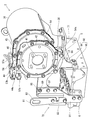
- both sides along the output shaft 3 are left and right
- the cooling fan 9 arrangement side is the front side
- the flywheel 11 arrangement side is the rear side
- the exhaust manifold 7 arrangement side is The left side and the intake manifold 6 arrangement side are referred to as the right side, and these are used as a reference for the positional relationship between the four sides and the top and bottom in the engine 1 for convenience.
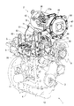
- an engine 1 as a prime mover mounted on a work machine such as a construction civil machine or an agricultural machine has a continuously regenerative exhaust gas purification device 2 (DPF).
- the exhaust gas purification device 2 removes particulate matter (PM) in the exhaust gas discharged from the engine 1 and reduces carbon monoxide (CO) and hydrocarbons (HC) in the exhaust gas.
- the engine 1 includes a cylinder block 4 that incorporates an output shaft 3 (crankshaft) and a piston (not shown).
- a cylinder head 5 is mounted on the cylinder block 4.
- An intake manifold 6 is disposed on the right side surface of the cylinder head 5.
- An exhaust manifold 7 is disposed on the left side surface of the cylinder head 5. That is, the intake manifold 6 and the exhaust manifold 7 are distributed and arranged on both side surfaces along the output shaft 3 in the engine 1.
- a head cover 8 is disposed on the upper surface of the cylinder head 5.
- a cooling fan 9 is provided on one side of the engine 1 that intersects the output shaft 3, specifically, on the front surface of the cylinder block 4.
- a mounting plate 10 is provided on the rear surface of the cylinder block 4.
- the flywheel 11 is arranged so as to overlap the mounting plate 10.
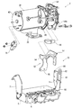
- a fuel supply pump 14 for supplying fuel is mounted on the right side surface of the cylinder block 4 above the oil filter 13 (below the intake manifold 6).
- the engine 1 is provided with injectors 15 for four cylinders with electromagnetic opening / closing control type fuel injection valves (not shown).
- a fuel tank (not shown) mounted on the work machine is connected to each injector 15 via a fuel supply pump 14, a cylindrical common rail 16 and a fuel filter (not shown).
- the fuel in the fuel tank is pumped from the fuel supply pump 14 to the common rail 16 via a fuel filter (not shown), and high-pressure fuel is stored in the common rail 16.
- a fuel filter not shown
- high-pressure fuel is stored in the common rail 16.
- An engine starter 18 is provided on the mounting plate 10.
- the pinion gear 127 of the engine starter 18 is engaged with the ring gear 124 of the flywheel 11 (see FIGS. 16 and 17).
- the cooling water pump 21 is disposed coaxially with the fan shaft of the cooling fan 9 on the front side (cooling fan 9 side) of the cylinder head 5.
- an alternator 23 is provided as a generator that generates power using the power of the engine 1.
- the cooling water pump 21 and the alternator 23 are driven together with the cooling fan 9 via the cooling fan driving V-belt 22. Cooling water in the radiator 19 (see FIGS. 3 and 4) mounted on the work machine is supplied to the cylinder block 4 and the cylinder head 5 by driving the cooling water pump 21, thereby cooling the engine 1.
- engine leg mounting portions 24 are respectively provided on the left and right side surfaces of the oil pan 12. Each engine leg mounting portion 24 can be bolted to an engine leg (not shown) having vibration-proof rubber.
- the oil pan 12 is sandwiched between a pair of left and right engine support chassis 25 in the work machine, and the engine leg mounting portion 24 on the oil pan 12 side is bolted to each engine support chassis 25, thereby The engine support chassis 25 supports the engine 1.
- an air cleaner (not shown) is connected to the inlet of the intake manifold 6 via an EGR device 26 (exhaust gas recirculation device).
- the EGR device 26 is mainly disposed on the right side of the engine 1, specifically, on the right side of the cylinder head 5.
- the fresh air (external air) sucked into the air cleaner is dust-removed and purified by the air cleaner, then sent to the intake manifold 6 via the EGR device 26 and supplied to each cylinder of the engine 1.
- the EGR device 26 includes an EGR main body case 27 that mixes a part of the exhaust gas (EGR gas) of the engine 1 and fresh air and supplies the mixture to the intake manifold 6, and an intake throttle member 28 that causes the EGR main body case 27 to communicate with an air cleaner. And a recirculation exhaust gas pipe 30 connected to the exhaust manifold 7 via an EGR cooler 29, and an EGR valve member 31 for communicating the EGR main body case 27 with the recirculation exhaust gas pipe 30.
- EGR gas exhaust gas
- an intake throttle member 28 is connected to the intake manifold 6 via an EGR main body case 27.
- An outlet side of the recirculation exhaust gas pipe 30 is connected to the EGR main body case 27.
- the inlet side of the recirculated exhaust gas pipe 30 is connected to the exhaust manifold 7 via the EGR cooler 29.
- fresh air is supplied from the air cleaner through the intake throttle member 28 into the EGR main body case 27, while EGR gas is supplied from the exhaust manifold 7 into the EGR main body case 27.
- EGR gas is supplied from the exhaust manifold 7 into the EGR main body case 27.
- the mixed gas is supplied to the intake manifold 6.
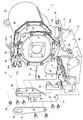
- the exhaust gas purification device 2 is disposed on the upper surface side of the engine 1 above the exhaust manifold 7, that is, above the exhaust manifold 7 on the left side of the cylinder head 5. In this case, the attitude of the exhaust gas purification device 2 is set so that the longitudinal direction of the exhaust gas purification device 2 extends in parallel with the output shaft 3 of the engine 1.
- a purification inlet pipe 36 is provided on the outer peripheral portion of the exhaust gas purification device 2 on the exhaust upstream side. The purification inlet pipe 36 is connected to the outlet portion of the exhaust manifold 7. Exhaust gas discharged from each cylinder of the engine 1 to the exhaust manifold 7 is discharged to the outside via the exhaust gas purification device 2 and the like.
- the exhaust gas purification device 2 includes a purification casing 38 having a purification inlet pipe 36. Inside the purification casing 38 is a diesel oxidation catalyst 39 such as platinum that generates nitrogen dioxide (NO 2 ), and a soot filter having a honeycomb structure that continuously oxidizes and removes the collected particulate matter (PM) at a relatively low temperature. 40 are arranged in series in the exhaust gas movement direction.
- the diesel oxidation catalyst 39 and the soot filter 40 correspond to a gas purification filter accommodated in the purification casing 38.
- a silencer or a tail pipe is connected to the exhaust gas outlet 41 of the purification casing 38 via an exhaust pipe, and the exhaust gas is discharged from the exhaust gas outlet 41 to the outside via the silencer or the tail pipe.
- nitrogen dioxide (NO 2 ) generated by the oxidation action of the diesel oxidation catalyst 39 is taken into the soot filter 40.
- Particulate matter contained in the exhaust gas of the engine 1 is collected by the soot filter 40 and continuously oxidized and removed by nitrogen dioxide (NO 2 ).
- the content of carbon monoxide (CO) and hydrocarbon (HC) in the exhaust gas of the engine 1 is reduced.
- a purification inlet pipe 36 is provided on the outer peripheral portion of the purification casing 38 on the upstream side of the exhaust.
- the purification inlet pipe 36 of the embodiment is formed in a half cylinder shape that opens upward.
- a rectangular upward opening end on the large diameter side of the purification inlet pipe 36 is welded and fixed to the outer periphery of the purification casing 38 so as to cover an exhaust gas inlet (not shown) formed in the purification casing 38.
- the exhaust gas intake side of the purification inlet pipe 36 is located on the center side in the longitudinal direction of the purification casing 38.
- the exhaust gas intake side of the purification inlet pipe 36 is fastened to the outlet portion of the exhaust manifold 7.
- the lid 42 is fixed by welding to the exhaust downstream end of the purification casing 38.
- An end of the purification casing 38 on the exhaust downstream side is closed by a lid 42.
- An exhaust gas outlet 41 is opened substantially at the center of the lid 42.
- An inlet lid 43 is welded and fixed to the exhaust upstream end of the purification casing 38.
- An end of the purification casing 38 on the upstream side of the exhaust is closed by an inlet side lid body 43.
- the purification casing 38 is provided with a thermistor type exhaust gas temperature sensor 57.
- a thermistor type exhaust gas temperature sensor 57 There are a pair of exhaust gas temperature sensors 57 of the embodiment, and a sensor pipe 57a is extended from each.
- the detection portion at the tip of each sensor pipe 57a enters the exhaust upstream side of the diesel oxidation catalyst 39 and between the diesel oxidation catalyst 39 and the soot filter 40, and detects the exhaust gas temperature in each space.
- the exhaust gas temperature sensor 57 converts the exhaust gas temperature into an electrical signal and outputs it to an engine controller (not shown).
- the exhaust pressure sensor 44 is attached to the purification casing 38.
- the exhaust pressure sensor 44 detects the pressure difference of the exhaust gas between the upstream side and the downstream side of the soot filter 40, converts the pressure difference of the exhaust gas into an electric signal, and sends it to an engine controller (not shown). It is configured to output. Based on the exhaust pressure difference between the upstream and downstream of the soot filter 40, the amount of particulate matter accumulated in the soot filter 40 is calculated, and the clogged state in the soot filter 40 is grasped.
- a sensor fastening portion 46 with a through hole is provided on the intermediate clamping flange 45 of the purification casing 38 so as to be positioned on the head cover 8 side in the outer peripheral portion of the purification casing 38.
- the exhaust pressure sensor 44 and the electrical wiring connector 57 b of each exhaust gas temperature sensor 57 provided integrally with the electrical wiring connector 44 a are attached to the sensor bracket 58.
- the sensor bracket 58 is made of aluminum formed in a substantially L-shaped plate shape, and is lightened.
- An exhaust pressure sensor 44 is attached to the horizontal plate portion of the sensor bracket 58 via a heat insulation and vibration prevention sheet (not shown), and each exhaust gas is attached to the vertical plate portion of the sensor bracket 58 via a heat insulation and vibration prevention sheet (not shown).
- the electrical wiring connector 57b of the temperature sensor 57 is attached vertically. With this configuration, since the electrical wiring connectors 44a and 57b of the various sensors 44 and 57 are grouped, the wiring relations for the electrical wiring connectors 44a and 57b can be easily integrated. Wiring work is also simplified.
- the exhaust pressure sensor 44 is connected to one end side of an upstream sensor pipe 47 and a downstream sensor pipe 48, respectively.
- the upstream and downstream sensor piping boss bodies 49 and 50 are provided in the purification casing 38 so as to sandwich the soot filter 40 in the purification casing 38.
- Fastening boss bodies 51 and 52 provided on the other end side of the sensor pipes 47 and 48 are fastened to the sensor pipe boss bodies 49 and 50 via pipe joint bolts 53.
- the exhaust pressure sensor 44 detects the difference between the exhaust gas pressure upstream (inflow) of the soot filter 40 and the exhaust gas pressure downstream (outflow) of the soot filter 40 (exhaust gas differential pressure). Is done. Since the residual amount of particulate matter in the exhaust gas collected by the soot filter 40 is proportional to the differential pressure of the exhaust gas, the exhaust pressure is increased when the amount of particulate matter remaining in the soot filter 40 increases more than a predetermined value. Based on the detection result of the sensor 44, regeneration control for reducing the amount of particulate matter in the soot filter 40 (for example, control for increasing the exhaust temperature) is executed. When the residual amount of the particulate matter further increases beyond the regeneration controllable range, the cleaning casing 38 is detached and disassembled, the soot filter 40 is cleaned, and the particulate matter is removed manually. Is called.
- the electrical wiring connectors 44a and 57b for the various sensors 44 and 57 (detection members) for the exhaust gas purification device 2 are arranged on the head cover 8 side in the outer peripheral portion of the exhaust gas purification device 2, the exhaust gas purification is performed.
- the electric wiring connectors 44a and 57b can be positioned at a height that is substantially the same as or lower than the upper end of the device 2, and the electric wiring connector 44a is arranged with respect to the total height of the engine 1 including the exhaust gas purification device 2. , 57b can be reduced or eliminated. For this reason, in the engine 1 to which the exhaust gas purification device 2 is assembled, it is effective to keep the overall height as low as possible, and contributes to the downsizing of the engine 1.
- the exhaust gas purification device 2 is supported above the exhaust manifold 7 on the upper surface side of the engine 1 so as to extend parallel to the output shaft 3 of the engine 1 with respect to the cylinder head 5 and the exhaust manifold 7. For this reason, the exhaust gas purification device 2 can be shipped after the exhaust gas purification device 2 is incorporated into the engine 1, but the exhaust gas purification device 2 is highly rigid using the cylinder head 5 and the exhaust manifold 7 which are high rigidity components of the engine 1.
- the exhaust gas purification device 2 can be prevented from being damaged due to vibration or the like. Further, the exhaust gas purification device 2 can be communicated with the exhaust manifold 7 at a close distance, so that the exhaust gas purification device 2 can be easily maintained at an appropriate temperature, and high exhaust gas purification performance can be maintained. As a result, the exhaust gas purification device 2 can also be reduced in size.
- the exhaust gas intake side of the purification inlet pipe 36 of the purification casing 38 is fastened to the outlet portion of the exhaust manifold 7.
- the exhaust gas from the exhaust manifold 7 is supplied to the exhaust gas purification device 2 via the purification inlet pipe 36.
- the exhaust manifold 7 also functions as a casing support that supports the exhaust gas purification device 2. In this case, the exhaust manifold 7 supports a longitudinal midway portion of the purification casing 38 via the purification inlet pipe 36.
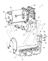
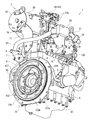
- the engine 1 is provided with an inlet side bracket body 71 and an outlet side bracket body 72 for supporting and fixing the exhaust gas purification device 2.
- the inlet side bracket body 71 and the outlet side bracket body 72 are formed wide in a direction intersecting the output shaft 3 of the engine 1.
- the inlet side bracket body 71 and the outlet side bracket body 72 are detachably fixed to the cylinder head 5 of the engine 1.
- the inlet side bracket body 71 and the outlet side bracket body 72 are erected on the front side and the rear side that intersect the output shaft 3 in the cylinder head 5.
- the inlet side bracket body 71 is located on the rear surface side of the cylinder head 5 and supports the exhaust upstream side of the purification casing 38.
- the outlet side bracket body 72 is located on the front side of the cylinder head and supports the exhaust downstream side of the purification casing 38.
- the inlet side bracket body 71 and the outlet side bracket body 72 correspond to a mounting base.
- the inlet side bracket body 71 is arranged on the rear surface side (above the mounting plate 10) of the cylinder head 5 as described above.
- the lower end side of the inlet side bracket body 71 is bolted to the rear surface of the cylinder head 5.
- An extension bracket 76 is bolted to the upper end side of the inlet side bracket body 71.
- the distal end side of the extension bracket 76 is fastened to an inlet side lid 43 that closes the exhaust upstream end of the purification casing 38 via bolts and nuts.
- the exhaust upstream side of the purification casing 38 is detachably fixed to the rear surface side of the cylinder head 5 via the inlet side bracket body 71.
- the outlet side bracket body 72 is arranged on the front side (cooling fan 9 side) of the cylinder head 5 as described above.
- the outlet side bracket body 72 of the embodiment is configured to be separated into an intake side bracket 91 and an exhaust side bracket 92.
- the lower end side of the intake side bracket 91 is bolted to the front side of the cylinder head 5.
- a reinforcing bracket 93 is bolted to the upper surface of the intake manifold 6.
- the front side of the reinforcing bracket 93 is overlapped with the upper and lower halfway part on the rear surface side of the intake side bracket 91, and both 91 and 93 are bolted.
- a first lifting bracket 81 described later is attached to the upper and lower halfway part on the front side of the intake side bracket 91.
- these three members 81, 91, 93 are fastened together with the reinforcing bracket 93 and the first lifting bracket 81 sandwiching the middle part of the intake side bracket 91.
- the exhaust side bracket 92 is formed by welding and fixing a rear frame plate 95 having a square cross section to the rear surface side of the front frame plate 94 having a substantially downward C opening.
- the base end side of the front frame plate 95 is bolted to the bracket fastening portion 54 a of the outlet holding flange 54 in the purification casing 38 via the spacer body 96. That is, one end side of the exhaust gas purification device 2 is connected to the exhaust side bracket 92.
- the intake side bracket 91 may be connected to one end side of the exhaust gas purification device 2.
- an embedded bolt 97 as a locking shaft body is provided on the front end side of the front frame plate 94 in the exhaust side bracket 92.
- the embedded bolt 97 projects forward from the front surface of the front frame plate 94.
- an upward opening temporary fixing notch 98 is formed on the upper end side of the intake side bracket 91. That is, a bolt hole for inserting the embedded bolt 97 formed on the upper end side of the intake side bracket 91 is cut out in an upwardly open shape to form a temporary fixing notch 98.
- An embedding bolt 97 of the front frame plate 94 can be locked to a temporary fixing notch 98 on the upper end side of the intake side bracket 91.
- the front end of the front frame plate 94 of the exhaust side bracket 92 is overlapped with the upper end of the rear surface of the intake side bracket 91, and the embedded bolt 97 is engaged with the temporary fixing notch 98.
- the bracket 92 and thus the purification casing 38 is supported.
- the exhaust downstream side of the purification casing 38 can be held at a predetermined position by the engagement of the embedded bolt 97 and the temporary fixing notch 98. That is, by engaging the embedded bolt 97 and the temporary fixing notch 98, the assembly position of the exhaust-side bracket 92 with respect to the intake-side bracket 91, and hence the mounting position of the exhaust gas purification device 2 with respect to the engine 1, can be easily determined.
- an embedded bolt 97 may be provided in the intake side bracket 91 and a temporary fixing notch 98 may be provided in the exhaust side bracket 92.
- the opening direction of the temporary fixing notch 98 may be set according to the positional relationship with the embedded bolt 97 and is not limited to the upward opening shape.
- the front end side of the front frame plate 94 in the exhaust side bracket 92 and the upper end side of the rear side of the intake side bracket 91 are bolted.
- a locking nut 99 is screwed into the embedding bolt 97 (tightening), and the one end sides of the intake side bracket 91 and the exhaust side bracket 92 are connected to each other.
- the lower end side of the rear frame plate 95 in the exhaust side bracket 92 is bolted to the left side front portion of the cylinder head 5.
- the exhaust downstream side of the purification casing 38 is detachably fixed to the front surface and the left front portion (front surface side) of the cylinder head 5 via the outlet side bracket body 72.
- the assembly position of the exhaust side bracket 92 with respect to the intake side bracket 91 and the mounting position of the exhaust gas purification device 2 with respect to the engine 1 can be easily determined by the engagement of the embedded bolt 97 and the temporary fixing notch 98. it can. Further, it is not necessary to perform assembly work such as bolt fastening or removal work while supporting the entire weight of the exhaust gas treatment device 2, and when the exhaust gas purification device 2 is loaded or unloaded, or assembling and disassembling the exhaust gas purification device 2. The labor at the time of work can be greatly reduced.
- the intake-side bracket 91 and the exhaust-side bracket 92 are used as the mounting base that supports one end side of the exhaust gas purification device 2 (exit-side bracket body 72).
- the intake side bracket 91 and the exhaust side bracket 92 are fastened to each other, and the other end sides of the intake side bracket 91 and the exhaust side bracket 92 are connected to the engine 1 (cylinder head 5) side. Therefore, the mounting base (exit-side bracket body 72) is separated into the intake-side bracket 91 and the exhaust-side bracket 92, and the brackets 91 and 92 are designed to reduce the weight of each bracket.
- the exhaust gas purification device 2 can be stably mounted on the engine 1 with sufficient support strength secured by fastening. Therefore, it is possible to prevent deterioration and damage of the exhaust gas purification device 2 due to vibrations of the engine 1 and the like, thereby contributing to improvement in durability of the exhaust gas purification device 2.
- one end side of the exhaust gas purification device 2 is connected to one of the intake side bracket 91 and the exhaust side bracket 92, so that the intake side bracket 91 and the exhaust-side bracket 92 can be mounted on and removed from the engine 1 in a state where one of the exhaust-side brackets 92 is connected to one end of the exhaust-gas purification device 2, and the assembly workability of the exhaust-gas purification device 2 with respect to the engine 1 Improvements can be made.
- the other of the intake side bracket 91 and the exhaust side bracket 92 can be used as a mounting seat for a lifting bracket 81 for lifting the engine 1, for example.
- a temporary fixing notch 98 is formed in one of the intake side bracket 91 and the exhaust side bracket 92, and a locking shaft body 97 provided on the remaining other side. Is configured to be able to be locked to the temporary fixing notch 98, and by engaging the locking shaft body 97 and the temporary fixing notch 98, the other bracket 92 (to one bracket 91 (92) is connected. 91), that is, the mounting position of the exhaust gas purification device 2 with respect to the engine 1 can be easily determined.
- the reference position for mounting the exhaust gas purifying device 2 with respect to the engine 1 can be set with high accuracy. For this reason, even if the exhaust gas purification device 2 is heavier than a muffler or the like as a post-processing device, it can be properly mounted at a predetermined position.
- the engine 1 includes a pair of lifting hardware 81 and 82.
- the pair of lifting brackets 81 and 82 are arranged separately on both side surfaces intersecting the output shaft 3 in the engine 1.
- the lifting brackets 81 and 82 of the embodiment are distributed to the front side and the rear side of the cylinder head 5 in the engine 1.
- the second lifting bracket 82 is a long plate-shaped metal plate.
- a through suspension hole 86 for inserting a wire rope or the like is formed on the upper end side of the second lifting bracket 82, for example.
- the lower end side of the second lifting bracket 82 is bolted to the rear surface of the cylinder head 5.
- the first lifting bracket 81 is also a long plate metal plate. On the upper end side of the first lifting bracket 81, a through suspension hole 83 for inserting a wire rope or the like is formed.
- the lower end side of the second lifting bracket 82 is bolted to the rear surface of the cylinder head 5.
- the lower end side of the first lifting bracket 81 is bolted to the intake side bracket 91.
- the upper and lower middle portions of the intake side bracket 91 are clamped by the reinforcing bracket 93 bolted to the upper surface of the intake manifold 6 and the lower end side of the first lifting bracket 81, and these three members 81, 91 are held in the clamped state. , 93 are tightened together.
- the first lifting bracket 81 may be provided on the exhaust side bracket 92.
- the strength of the first lifting bracket 81 is set to be smaller than the strength of the intake side bracket 91 and the reinforcing bracket 93. For this reason, for example, when an excessive external force is applied when the engine 1 is lifted, the first lifting bracket 81 is plastically deformed or damaged before the intake side bracket 91 and the reinforcing bracket 93. That is, the deformation of the intake side bracket 91 and the reinforcing bracket 93 due to the lifting of the engine 1 can be prevented, and as a result, the application of external force to the exhaust gas purification device 2 when the engine 1 is lifted can be suppressed.
- the lower end side of the lifting bracket 81 for lifting the engine 1 is fastened to one of the intake side bracket 91 and the exhaust side bracket 92.
- the engine 1 can be connected to the engine 1 while suppressing the number of parts by using either one of the brackets 91 and 92, which are high-rigidity parts that support the exhaust gas purification device 2, as a fastening portion for the lifting bracket 81.
- the lifting bracket 81 can be firmly fastened (the connection strength of the lifting bracket 81 to the engine 1 can be secured).
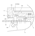
- the mounting plate 10 is provided on one side surface (specifically, the rear surface of the cylinder block 4) that intersects the output shaft 3 in the engine 1.
- the flywheel 11 is arranged so as to overlap the mounting plate 10.
- a flywheel 11 is pivotally supported on the output shaft 3. Therefore, the mounting plate 10 is located between the rear surface of the cylinder block 4 and the flywheel 11.
- a recess 121 is formed on the inner surface of the flywheel 11 near the engine 1 (cylinder block 4).
- An annular output shaft pulser 122 is disposed in the recess 121.
- a pulsar engagement step portion 123 that protrudes toward the rear surface of the cylinder block 4 along the direction of the output shaft 3 is formed in the recess 121.
- the output shaft pulsar 122 is attached to the pulsar engagement step portion 123 by press fitting or shrink fitting.
- a ring gear 124 for the engine starter 18 is provided on the outer peripheral portion of the flywheel 11 on the inner surface side close to the engine 1 (cylinder block 4).
- a stepped gear engagement step portion 125 is formed on the outer peripheral portion on the inner surface side of the flywheel 11.
- the ring gear 124 is attached to the gear engagement step 125 by press fitting or shrink fitting. Therefore, the output shaft pulser 122 and the ring gear 124 are fitted and fixed to the flywheel 11 from the same side (the inner surface side close to the engine
- the output protrusion 122a is formed on the outer peripheral surface of the output shaft pulsar 122 as a detected portion that is arranged at every predetermined rotation angle (crank angle).
- a missing tooth portion 122b is formed in a portion corresponding to the top dead center (TDC) of the first or fourth cylinder.
- a rotation angle sensor 126 as a rotation angle detection member is provided on the right side of the mounting plate 10. The distal end side (detection side) of the rotation angle sensor 126 protrudes into the recess 121 and faces the output protrusion 122a and the missing tooth portion 122b on the outer peripheral portion on the inner surface side of the output shaft pulsar 122.
- the rotation angle sensor 126 detects the rotation angle (crank angle) of the output shaft 3, and the rotation angle of the output shaft 122 as the output protrusion 122 a of the output shaft pulsar 122 passes with the rotation of the output shaft 3. Output a signal.
- the engine starter 18 having a pinion gear 127 on the output shaft is mounted on the left side of the mounting plate 10.
- the pinion gear 127 of the engine starter 18 is meshed with the ring gear 124 of the flywheel 11.
- cranking is executed.
- a rotation angle signal output from a rotation angle sensor according to rotation of an output shaft (crankshaft) of an engine and a cam angle according to rotation of a cam shaft is performed in combination with the cam angle signal output from the sensor, and fuel injection and ignition for each cylinder are executed based on the cylinder discrimination result.
- the engine is driven by such fuel injection and ignition for each cylinder (see, for example, JP 2010-261322 A).
- the cylinder discrimination means that the rotation angle (rotation position) of the output shaft in one cycle (720 ° CA) in the engine is specified.
- a flywheel that rotates integrally with the output shaft is disposed on one side of the engine in the output shaft direction.
- a rotation angle sensor is arranged close to the outer peripheral side of the output shaft pulser attached to the flywheel.
- a flywheel housing is provided on one side in the output shaft direction of the engine, and the flywheel is accommodated in the flywheel housing.
- the rotation angle sensor is provided on the outer peripheral side of the flywheel housing so as to face the output shaft pulser.
- the thickness of the flywheel housing in the output shaft direction must be increased.
- the weight of the engine device as a whole increases by the amount of the flywheel housing, and the size of the engine device increases.
- the engine including the rotation angle detection member 126 for detecting the rotation angle of the output shaft 3 in the engine 1 and the output shaft pulser 122 provided in the flywheel 11 of the engine 1.
- a mounting plate 10 that supports an engine starter starter 18 is disposed between one side of the engine 1 and the flywheel 11 on one side of the engine 1 on the flywheel 11 side.
- the rotation angle detection member 126 is disposed on the mounting plate 10, and the rotation angle detection member 126 is opposed to the side surface of the output shaft pulsar 122 facing one side of the engine 1. Therefore, the rotation angle detecting member 126 is supported on the mounting plate 10 which is lighter than the flywheel housing. Can, flywheel housing is not needed which is a heavy object. Accordingly, the engine 1 can be reduced in weight and size.
- a recess 121 is formed on the inner surface side of the flywheel 11 near the engine 1, and the output shaft pulser 122 is disposed in the recess 121. Since the leading end side of the rotation angle detecting means 126 is inserted into the recess 121, the output shaft pulser 122 and the rotation angle detecting member 126 with respect to the flywheel 11 and the mounting plate 10. Can be arranged compactly. Accordingly, the thickness of the flywheel 11 and the mounting plate 10 in the direction of the output shaft 3 can be reduced, which contributes to space saving around the engine 1.
- a ring gear 124 for the engine starter 18 is provided on the outer peripheral portion of the flywheel 11 on the inner surface side close to the engine 1, and the output shaft pulser is provided.
- 122 and the ring gear 124 are fitted and fixed to the flywheel 11 from the same side, so that the output shaft pulser 122 and the ring gear 124 are interposed between the flywheel 11 and the mounting plate 10. Will be located. Accordingly, it is possible to prevent dust and foreign matter from entering the vicinity of the output shaft pulser 122 and the ring gear 124.
Landscapes
- Engineering & Computer Science (AREA)
- Chemical & Material Sciences (AREA)
- Combustion & Propulsion (AREA)
- Mechanical Engineering (AREA)
- General Engineering & Computer Science (AREA)
- Chemical Kinetics & Catalysis (AREA)
- Exhaust Gas After Treatment (AREA)
- Processes For Solid Components From Exhaust (AREA)
Priority Applications (4)
| Application Number | Priority Date | Filing Date | Title |
|---|---|---|---|
| EP13813671.8A EP2889464B1 (en) | 2012-07-05 | 2013-07-05 | Engine device |
| KR1020147035316A KR102069917B1 (ko) | 2012-07-05 | 2013-07-05 | 엔진 장치 |
| US14/412,003 US9512778B2 (en) | 2012-07-05 | 2013-07-05 | Engine apparatus |
| CN201380035744.0A CN104411939B (zh) | 2012-07-05 | 2013-07-05 | 发动机装置 |
Applications Claiming Priority (4)
| Application Number | Priority Date | Filing Date | Title |
|---|---|---|---|
| JP2012151389A JP2014013026A (ja) | 2012-07-05 | 2012-07-05 | エンジン装置 |
| JP2012-151389 | 2012-07-05 | ||
| JP2012-165920 | 2012-07-26 | ||
| JP2012165920A JP5981255B2 (ja) | 2012-07-26 | 2012-07-26 | エンジン装置 |
Publications (1)
| Publication Number | Publication Date |
|---|---|
| WO2014007373A1 true WO2014007373A1 (ja) | 2014-01-09 |
Family
ID=49882124
Family Applications (1)
| Application Number | Title | Priority Date | Filing Date |
|---|---|---|---|
| PCT/JP2013/068519 WO2014007373A1 (ja) | 2012-07-05 | 2013-07-05 | エンジン装置 |
Country Status (5)
| Country | Link |
|---|---|
| US (1) | US9512778B2 (ko) |
| EP (1) | EP2889464B1 (ko) |
| KR (1) | KR102069917B1 (ko) |
| CN (1) | CN104411939B (ko) |
| WO (1) | WO2014007373A1 (ko) |
Cited By (3)
| Publication number | Priority date | Publication date | Assignee | Title |
|---|---|---|---|---|
| JP2016079867A (ja) * | 2014-10-15 | 2016-05-16 | ヤンマー株式会社 | エンジン装置 |
| CN106062335A (zh) * | 2014-03-20 | 2016-10-26 | 洋马株式会社 | 发动机装置以及搭载其的固定型作业机 |
| EP3208439A4 (en) * | 2014-10-15 | 2017-12-13 | Yanmar Co., Ltd. | Engine device |
Families Citing this family (6)
| Publication number | Priority date | Publication date | Assignee | Title |
|---|---|---|---|---|
| JP6451240B2 (ja) | 2014-11-17 | 2019-01-16 | コベルコ建機株式会社 | 建設機械 |
| CN113217166B (zh) * | 2016-04-08 | 2023-04-14 | 洋马动力科技有限公司 | 发动机装置 |
| JP6731876B2 (ja) * | 2017-03-24 | 2020-07-29 | ヤンマーパワーテクノロジー株式会社 | エンジン装置 |
| JP6737741B2 (ja) | 2017-06-15 | 2020-08-12 | ヤンマーパワーテクノロジー株式会社 | エンジン |
| JP6515967B2 (ja) * | 2017-08-24 | 2019-05-22 | マツダ株式会社 | 車両用パワートレインユニット |
| JP7311475B2 (ja) * | 2020-09-28 | 2023-07-19 | 株式会社クボタ | 作業車 |
Citations (11)
| Publication number | Priority date | Publication date | Assignee | Title |
|---|---|---|---|---|
| JPH0533693A (ja) * | 1991-07-24 | 1993-02-09 | Nissan Motor Co Ltd | エンジン用クランク角センサの取付装置 |
| JPH1016573A (ja) * | 1996-06-28 | 1998-01-20 | Suzuki Motor Corp | エンジンマウントブラケット |
| JP2000145430A (ja) | 1998-11-13 | 2000-05-26 | Ibiden Co Ltd | 排気ガス浄化装置 |
| JP2003027922A (ja) | 2001-07-13 | 2003-01-29 | Ibiden Co Ltd | 排気ガス浄化装置 |
| JP2004225794A (ja) * | 2003-01-22 | 2004-08-12 | Yanmar Co Ltd | ベルト張力調整装置 |
| US20060021593A1 (en) * | 2004-08-02 | 2006-02-02 | Banks Clayton E Jr | Skid steer loader including muffler support for engine |
| JP2010071176A (ja) | 2008-09-18 | 2010-04-02 | Yanmar Co Ltd | エンジン装置 |
| JP2010071177A (ja) * | 2008-09-18 | 2010-04-02 | Yanmar Co Ltd | エンジン装置 |
| JP2010174810A (ja) * | 2009-01-30 | 2010-08-12 | Yanmar Co Ltd | 横型エンジン |
| JP2010261322A (ja) | 2009-04-30 | 2010-11-18 | Yanmar Co Ltd | エンジン |
| JP2012057656A (ja) * | 2010-09-06 | 2012-03-22 | Kawasaki Heavy Ind Ltd | エンジンのバランサ軸構造 |
Family Cites Families (11)
| Publication number | Priority date | Publication date | Assignee | Title |
|---|---|---|---|---|
| JPS6181034A (ja) | 1984-09-28 | 1986-04-24 | Sony Corp | 受信装置 |
| US5944398A (en) | 1998-03-20 | 1999-08-31 | Wei Shun Enterprise Co., Ltd. | Casing having right and left side plates adapted to cover right and left openings of the casing without using locking screws |
| CN201144997Y (zh) * | 2008-01-23 | 2008-11-05 | 青岛金环汽配制造有限公司 | 一种汽车发动机飞轮总成及安装有该飞轮总成的发动机 |
| US8191668B2 (en) * | 2008-08-07 | 2012-06-05 | Caterpillar Inc. | Mounting assembly for emissions control system |
| WO2010032646A1 (ja) * | 2008-09-18 | 2010-03-25 | ヤンマー株式会社 | エンジン装置 |
| JP5483857B2 (ja) * | 2008-10-20 | 2014-05-07 | ヤンマー株式会社 | 走行車両搭載用のエンジン装置 |
| CN201326684Y (zh) | 2008-12-19 | 2009-10-14 | 奇瑞汽车股份有限公司 | 发动机飞轮总成 |
| CN201363226Y (zh) * | 2008-12-31 | 2009-12-16 | 哈尔滨东安汽车动力股份有限公司 | 新型车用发动机起动装置 |
| CN102365431B (zh) * | 2009-03-26 | 2013-01-02 | 株式会社小松制作所 | 内燃机的排气气体净化装置 |
| JP5616194B2 (ja) * | 2010-01-14 | 2014-10-29 | 株式会社クボタ | 排気処理装置付きエンジン |
| JP2011196194A (ja) * | 2010-03-17 | 2011-10-06 | Yanmar Co Ltd | 排気ガス浄化装置 |
-
2013
- 2013-07-05 US US14/412,003 patent/US9512778B2/en active Active
- 2013-07-05 CN CN201380035744.0A patent/CN104411939B/zh not_active Expired - Fee Related
- 2013-07-05 EP EP13813671.8A patent/EP2889464B1/en not_active Not-in-force
- 2013-07-05 WO PCT/JP2013/068519 patent/WO2014007373A1/ja active Application Filing
- 2013-07-05 KR KR1020147035316A patent/KR102069917B1/ko active IP Right Grant
Patent Citations (11)
| Publication number | Priority date | Publication date | Assignee | Title |
|---|---|---|---|---|
| JPH0533693A (ja) * | 1991-07-24 | 1993-02-09 | Nissan Motor Co Ltd | エンジン用クランク角センサの取付装置 |
| JPH1016573A (ja) * | 1996-06-28 | 1998-01-20 | Suzuki Motor Corp | エンジンマウントブラケット |
| JP2000145430A (ja) | 1998-11-13 | 2000-05-26 | Ibiden Co Ltd | 排気ガス浄化装置 |
| JP2003027922A (ja) | 2001-07-13 | 2003-01-29 | Ibiden Co Ltd | 排気ガス浄化装置 |
| JP2004225794A (ja) * | 2003-01-22 | 2004-08-12 | Yanmar Co Ltd | ベルト張力調整装置 |
| US20060021593A1 (en) * | 2004-08-02 | 2006-02-02 | Banks Clayton E Jr | Skid steer loader including muffler support for engine |
| JP2010071176A (ja) | 2008-09-18 | 2010-04-02 | Yanmar Co Ltd | エンジン装置 |
| JP2010071177A (ja) * | 2008-09-18 | 2010-04-02 | Yanmar Co Ltd | エンジン装置 |
| JP2010174810A (ja) * | 2009-01-30 | 2010-08-12 | Yanmar Co Ltd | 横型エンジン |
| JP2010261322A (ja) | 2009-04-30 | 2010-11-18 | Yanmar Co Ltd | エンジン |
| JP2012057656A (ja) * | 2010-09-06 | 2012-03-22 | Kawasaki Heavy Ind Ltd | エンジンのバランサ軸構造 |
Non-Patent Citations (1)
| Title |
|---|
| See also references of EP2889464A4 |
Cited By (4)
| Publication number | Priority date | Publication date | Assignee | Title |
|---|---|---|---|---|
| CN106062335A (zh) * | 2014-03-20 | 2016-10-26 | 洋马株式会社 | 发动机装置以及搭载其的固定型作业机 |
| JP2016079867A (ja) * | 2014-10-15 | 2016-05-16 | ヤンマー株式会社 | エンジン装置 |
| EP3208439A4 (en) * | 2014-10-15 | 2017-12-13 | Yanmar Co., Ltd. | Engine device |
| US10669913B2 (en) | 2014-10-15 | 2020-06-02 | Yanmar Co., Ltd. | Engine apparatus |
Also Published As
| Publication number | Publication date |
|---|---|
| US9512778B2 (en) | 2016-12-06 |
| EP2889464B1 (en) | 2017-07-05 |
| EP2889464A4 (en) | 2016-09-28 |
| US20150198086A1 (en) | 2015-07-16 |
| CN104411939A (zh) | 2015-03-11 |
| EP2889464A1 (en) | 2015-07-01 |
| KR20150033609A (ko) | 2015-04-01 |
| KR102069917B1 (ko) | 2020-01-23 |
| CN104411939B (zh) | 2017-07-07 |
Similar Documents
| Publication | Publication Date | Title |
|---|---|---|
| WO2014007373A1 (ja) | エンジン装置 | |
| JP5981255B2 (ja) | エンジン装置 | |
| JP5882158B2 (ja) | エンジン装置 | |
| WO2013108724A1 (ja) | 排気ガス浄化装置 | |
| JP6192576B2 (ja) | エンジン装置 | |
| WO2013099980A1 (ja) | エンジン装置 | |
| JP5843608B2 (ja) | エンジン装置 | |
| KR20170054494A (ko) | 엔진 장치 | |
| JP5889140B2 (ja) | エンジン装置 | |
| JP5939921B2 (ja) | エンジン装置 | |
| WO2014007374A1 (ja) | エンジン装置 | |
| JP6033026B2 (ja) | エンジン装置 | |
| WO2013108667A1 (ja) | 排気ガス浄化装置 | |
| JP2013160146A (ja) | 排気ガス浄化装置 | |
| JP5906149B2 (ja) | エンジン装置 | |
| JP2013160145A (ja) | 排気ガス浄化装置 | |
| JP2014013026A (ja) | エンジン装置 | |
| JP5872301B2 (ja) | 排気ガス浄化装置 | |
| JP2013148035A (ja) | 排気ガス浄化装置 | |
| JP6129733B2 (ja) | エンジン装置 |
Legal Events
| Date | Code | Title | Description |
|---|---|---|---|
| 121 | Ep: the epo has been informed by wipo that ep was designated in this application |
Ref document number: 13813671 Country of ref document: EP Kind code of ref document: A1 |
|
| ENP | Entry into the national phase |
Ref document number: 20147035316 Country of ref document: KR Kind code of ref document: A |
|
| WWE | Wipo information: entry into national phase |
Ref document number: 14412003 Country of ref document: US |
|
| NENP | Non-entry into the national phase |
Ref country code: DE |
|
| REEP | Request for entry into the european phase |
Ref document number: 2013813671 Country of ref document: EP |
|
| WWE | Wipo information: entry into national phase |
Ref document number: 2013813671 Country of ref document: EP |