WO2014007122A1 - Circuit magnétique - Google Patents
Circuit magnétique Download PDFInfo
- Publication number
- WO2014007122A1 WO2014007122A1 PCT/JP2013/067505 JP2013067505W WO2014007122A1 WO 2014007122 A1 WO2014007122 A1 WO 2014007122A1 JP 2013067505 W JP2013067505 W JP 2013067505W WO 2014007122 A1 WO2014007122 A1 WO 2014007122A1
- Authority
- WO
- WIPO (PCT)
- Prior art keywords
- magnetic circuit
- magnet
- diameter side
- magnetic
- arc
- Prior art date
Links
Images


Classifications
-
- H—ELECTRICITY
- H01—ELECTRIC ELEMENTS
- H01F—MAGNETS; INDUCTANCES; TRANSFORMERS; SELECTION OF MATERIALS FOR THEIR MAGNETIC PROPERTIES
- H01F7/00—Magnets
- H01F7/02—Permanent magnets [PM]
- H01F7/0205—Magnetic circuits with PM in general
-
- G—PHYSICS
- G01—MEASURING; TESTING
- G01R—MEASURING ELECTRIC VARIABLES; MEASURING MAGNETIC VARIABLES
- G01R33/00—Arrangements or instruments for measuring magnetic variables
- G01R33/20—Arrangements or instruments for measuring magnetic variables involving magnetic resonance
- G01R33/28—Details of apparatus provided for in groups G01R33/44 - G01R33/64
- G01R33/38—Systems for generation, homogenisation or stabilisation of the main or gradient magnetic field
- G01R33/3806—Open magnet assemblies for improved access to the sample, e.g. C-type or U-type magnets
-
- G—PHYSICS
- G01—MEASURING; TESTING
- G01R—MEASURING ELECTRIC VARIABLES; MEASURING MAGNETIC VARIABLES
- G01R33/00—Arrangements or instruments for measuring magnetic variables
- G01R33/20—Arrangements or instruments for measuring magnetic variables involving magnetic resonance
- G01R33/28—Details of apparatus provided for in groups G01R33/44 - G01R33/64
- G01R33/38—Systems for generation, homogenisation or stabilisation of the main or gradient magnetic field
- G01R33/383—Systems for generation, homogenisation or stabilisation of the main or gradient magnetic field using permanent magnets
-
- G—PHYSICS
- G01—MEASURING; TESTING
- G01N—INVESTIGATING OR ANALYSING MATERIALS BY DETERMINING THEIR CHEMICAL OR PHYSICAL PROPERTIES
- G01N24/00—Investigating or analyzing materials by the use of nuclear magnetic resonance, electron paramagnetic resonance or other spin effects
- G01N24/10—Investigating or analyzing materials by the use of nuclear magnetic resonance, electron paramagnetic resonance or other spin effects by using electron paramagnetic resonance
-
- G—PHYSICS
- G01—MEASURING; TESTING
- G01R—MEASURING ELECTRIC VARIABLES; MEASURING MAGNETIC VARIABLES
- G01R33/00—Arrangements or instruments for measuring magnetic variables
- G01R33/20—Arrangements or instruments for measuring magnetic variables involving magnetic resonance
- G01R33/28—Details of apparatus provided for in groups G01R33/44 - G01R33/64
- G01R33/38—Systems for generation, homogenisation or stabilisation of the main or gradient magnetic field
- G01R33/387—Compensation of inhomogeneities
- G01R33/3873—Compensation of inhomogeneities using ferromagnetic bodies ; Passive shimming
-
- G—PHYSICS
- G01—MEASURING; TESTING
- G01R—MEASURING ELECTRIC VARIABLES; MEASURING MAGNETIC VARIABLES
- G01R33/00—Arrangements or instruments for measuring magnetic variables
- G01R33/20—Arrangements or instruments for measuring magnetic variables involving magnetic resonance
- G01R33/60—Arrangements or instruments for measuring magnetic variables involving magnetic resonance using electron paramagnetic resonance
Definitions
- the present invention relates to a magnetic circuit that generates magnetic resonance in an object.
- active oxygen is generated by external factors such as radiation and ultraviolet rays, or by internal factors such as hypoxia and inflammation. Therefore, accurate measurement of free radicals such as active oxygen in the body is important for the health and welfare of the public, such as the evaluation and creation of antioxidant drugs.
- Patent Document 1 describes a measuring device that performs measurements necessary to acquire information about free radicals in an animal body.
- the measuring device uses a first external magnetic field generator for ESR (Electron Spin Resonance) excitation and a second external magnetic field generator for MRI (Magnetic Resonance Imaging) excitation for a coil moving in a linear direction. Is applied.
- ESR measures signals generated by electron spin resonance and acquires information on free radicals in a living body housed in a coil.
- MRI measures a signal generated by nuclear magnetic resonance and acquires information on the form of a living body.
- the measuring device supplements the functional information of free radicals obtained by ESR with the information obtained by MRI, and acquires information on free radicals in the animal body.
- the measurement device of Patent Document 1 causes the electron spin in the living body to transition by the Overhauser effect, and causes the energy transition in the nuclear spin to display the functional image and the morphological image in each part inside the living body. It is also used as an electronic multiplex magnetic resonance measuring apparatus.
- Patent Document 2 discloses a technique of applying a first magnetic field for ESR measurement and a second magnetic field for MRI measurement to a moving coil placed on a rotary table.
- the measurement device In order for the measurement device to measure ESR with high sensitivity, it is desirable to apply a uniform magnetic field for a long time to sufficiently excite electron spin in the living body.
- the relaxation time after electron spin excitation it is desirable to perform MRI excitation at a short time interval after ESR excitation, so the rotation speed of the turntable cannot be reduced. Therefore, it is necessary to widen the uniform magnetic field space, and the first external magnetic field generator is provided with a plurality of disk-shaped magnets juxtaposed.
- the uniform magnetic field space is a circle in plan view near the center of each of the first external magnetic field generators. It is limited to the shape space. Therefore, the uniform magnetic field space formed by the first external magnetic field generator is still narrow in order to sufficiently excite the electron spin, so that the time for applying the magnetic field by the first external magnetic field generator is insufficient. was there.
- the present invention has been made based on such problems, and an object thereof is to provide a magnetic circuit capable of applying a magnetic field to a target for a sufficient time.
- a magnetic circuit according to the present invention includes two arc-shaped magnets arranged opposite to each other, and two arc-shaped yokes arranged opposite to each other in the same direction as the two magnets with the two magnets interposed therebetween.
- the magnet is arcuate, a magnetic field can be applied to the object for a sufficient time.
- the two magnets are formed by arranging a plurality of small magnets along a connecting portion that connects a large-diameter arc portion, a small-diameter arc portion, and ends of the two arc portions. It is characterized by.
- the magnet is formed including the large-diameter arc portion, the small-diameter arc portion, and the connecting portion connecting the ends of the two arc portions, so that the magnetic field can be made uniform in a wide space. it can.
- the magnetic circuit according to the present invention includes two arc-shaped magnetic pole pieces arranged between the two magnets in the same direction as the two magnets, and an outer periphery of each magnetic pole piece, toward the other magnetic pole piece. And a protruding piece that protrudes.
- the pole piece is arcuate, a magnetic field can be applied to the object for a sufficient time.
- the magnetic circuit according to the present invention is characterized in that the protruding piece includes a large-diameter side protruding piece positioned on the large-diameter side of the magnetic pole piece and a small-diameter side protruding piece positioned on the small-diameter side of the magnetic pole piece. To do.
- the magnetic field can be made uniform in a wide space.
- the magnetic circuit according to the present invention is characterized in that the yoke includes a plurality of holes along a similar arc similar to the outer periphery of the magnet.
- the magnetic field strength can be partially adjusted by, for example, appropriately screwing a screw into the hole.
- the magnetic circuit according to the present invention includes a plate-like auxiliary yoke that connects the two yokes.
- the magnetic flux can be effectively utilized by providing the auxiliary yoke.
- the magnetic circuit according to the present invention is characterized in that the auxiliary yoke is provided along the outer circumference on the large diameter side of the two yokes, and one end side in the longitudinal direction is thicker than the other end side.
- the present invention when one end side in the longitudinal direction of the auxiliary yoke is thicker than the other end side, when another magnetic circuit is provided on one end side, the influence of the magnetic field leaking from the other magnetic circuit is suppressed. Can do.
- the magnetic circuit according to the present invention includes an auxiliary magnet attached to the magnet.
- the magnetic field strength can be partially adjusted by providing the auxiliary magnet.
- the magnetic circuit according to the present invention is characterized in that the auxiliary magnet is fixed to the one end side inside the connecting portion.
- the auxiliary magnet when another magnetic circuit is provided on one end side, the auxiliary magnet is fixed to the one end side on the inner side of the connecting arc portion, thereby preventing the magnetic field leaking from the other magnetic circuit. The influence can be suppressed.
- the magnetic circuit according to the present invention is characterized in that a non-magnetic plate is disposed between the magnet and the yoke facing the magnet.
- the magnetic field strength of the entire magnetic circuit can be adjusted by the nonmagnetic plate.
- the magnetic field can be applied to the measurement object for a sufficient time.
- FIG. 3 is a schematic plan view showing a first magnetic pole piece. It is a disassembled perspective view of a 2nd magnetic pole. It is a graph which shows the magnetic field intensity in the 1st magnetic circuit. It is the typical perspective view shown about the back yoke.
- the magnetic field application device includes a coil 5, a motor 41, a machine base 42, a rotary shaft 43, a rotary base 44, a first magnetic circuit 10, and a second magnetic circuit 30.
- the first magnetic circuit 10 includes a first magnetic pole 1, a second magnetic pole 2, a back yoke 3 that is a third yoke, a mounting table 4, and a column 6.
- the second magnetic circuit 30 includes magnetic poles 31 and 32, a back yoke 33, and a mounting table 34.
- the machine base 42 in the rotating device has a cylindrical shape, and a motor 41 is embedded therein.
- a rotating shaft 43 extending in the vertical direction protrudes from the machine base 42.
- a rotating table 44 At the upper end of the rotating shaft 43, there is provided a rotating table 44 that is disk-shaped and fixed coaxially to the rotating shaft 43.
- the control unit 8 is connected to the motor 41, controls the operation and stop of the motor 41, and acquires information about the rotation angle of the rotating shaft 43.
- a cylindrical coil 5 is fixed laterally on the periphery of the upper surface of the turntable 44.
- the coil 5 is hollow and accommodates a living body 7 such as a mouse or a rat that is a measurement object.
- the living body 7 is an example, and for example, a semiconductor device or the like may be used as a measurement object in order to analyze a structure or a function.
- the coil 5 is connected to the control unit 8, and the control unit 8 transmits a signal having a predetermined frequency to the coil 5.
- an electron spin resonance signal is generated.
- nuclear magnetic resonance occurs in the living body 7, a nuclear magnetic resonance signal is generated.
- the coil 5 detects the electron spin resonance signal and the nuclear magnetic resonance signal and transmits them to the control unit 8.
- the control unit 8 images the electron spin resonance signal and the nuclear magnetic resonance signal and displays them on the display unit 9.
- the display unit 9 is, for example, a liquid crystal display, a plasma display, an organic EL (Electro Luminescence) display, or the like.
- the first magnetic circuit 10 is used as an electron spin excitation device or the like in, for example, ESR or OMRI (Overhauser Magnetic Resonance Imaging System).
- the first magnetic pole 1 in the first magnetic circuit 10 has an arc shape in plan view along the outer edge of the rotating table 44 and is mounted on the mounting table 4.
- the second magnetic pole 2 has a shape symmetrical to the first magnetic pole 1 and is opposed to the first magnetic pole 1 in the vertical direction with a gap.
- the direction from the first magnetic pole 1 to the second magnetic pole 2 is the upward direction.
- such a direction is an example and is not particularly limited. Therefore, the first magnetic pole 1 and the second magnetic pole 2 do not have to have an arc shape in plan view as long as they have an arc shape.
- the first magnetic pole 1 and the second magnetic pole 2 are connected to each other by a first yoke 11 and a second yoke 21 which will be described later via a back yoke 3 provided to effectively use magnetic flux.
- the second magnetic pole 2 is supported by a column 6 provided along the back yoke 3.
- the first magnetic pole 1 and the second magnetic pole 2 generate a magnetic field in the gap.
- a part of the turntable 44 is disposed so as to pass through the gap between the first magnetic pole 1 and the second magnetic pole 2. When the turntable 44 rotates about the rotation shaft 43, the coil 5 passes through the gap.
- a second magnetic circuit 30 is provided at a position separated from the first magnetic circuit 10 in the clockwise direction along the outer edge of the turntable 44.
- the second magnetic circuit 30 is used as a nuclear spin excitation device or the like in MRI or OMRI.
- two magnetic poles 31 and 32 each having a disk-shaped magnet are arranged to face each other with a gap therebetween. Thereby, the second magnetic circuit 30 generates a magnetic field in the gap.
- the coil 5 passes through the gap between the magnetic pole 31 and the magnetic pole 32.
- the operation of the magnetic field application device will be described.
- the living body 7 is injected with a probe agent derivatized with a nitroxyl radical that is highly sensitive to redox metabolism in the living body.
- the control unit 8 transmits a signal instructing the start of operation to the motor 41.
- the motor 41 receives a signal from the control unit 8 and rotates the rotating shaft 43.
- the rotation speed is, for example, one rotation per second.
- the numerical values shown in the present embodiment are merely examples, and the present invention is not limited to this.
- the control unit 8 transmits a signal having a predetermined frequency that causes electron spin resonance to the coil 5 immediately before the coil 5 enters the gap in the first magnetic circuit 10 based on the information about the rotation angle of the rotating shaft 43.
- a magnetic field is applied to the coil 5, and electron spin resonance occurs in the living body 7.
- the coil 5 detects an electron spin resonance signal generated by electron spin resonance in the living body 7.
- the control unit 8 receives the electron spin resonance signal detected by the coil 5.
- the controller 8 stops transmitting a signal having a predetermined frequency that causes electron spin resonance when the coil 5 has passed through the gap of the first magnetic circuit 10. Further, the control unit 8 transmits a signal having a predetermined frequency that causes nuclear magnetic resonance to the coil 5 immediately before the coil 5 enters the gap in the second magnetic circuit 30.
- the coil 5 When the coil 5 receives a signal of a predetermined frequency and passes through the gap in the second magnetic circuit 30, a magnetic field is applied to the coil 5, and nuclear magnetic resonance occurs in the living body 7.
- the coil 5 detects a nuclear magnetic resonance signal generated by nuclear magnetic resonance.
- the control unit 8 receives the nuclear magnetic resonance signal detected by the coil 5.
- the control unit 8 stops transmitting a signal having a predetermined frequency that causes nuclear magnetic resonance.
- the control unit 8 transmits a signal instructing to stop the operation to the motor 41.
- the motor 41 receives a signal from the control unit 8 and stops the rotation of the rotating shaft 43.
- the control unit 8 performs a process of imaging free radicals of the living body 7 from the received electron spin resonance signal. Moreover, the control part 8 performs the process which images the external shape of the biological body 7 from the received nuclear magnetic resonance signal. Finally, the control unit 8 performs a process of combining the two images and causes the display unit 9 to display the combined image.
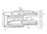
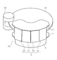
- FIG. 3 is a schematic perspective view showing the first magnetic circuit 10
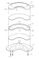
- FIG. 4 is an exploded perspective view of the first magnetic pole 1.
- the first magnetic pole 1 includes a first yoke 11, a first nonmagnetic plate 12, a first magnet 13, a first resin plate 14, a first magnetic pole piece 15, a first small diameter side protruding piece 161, 1 large-diameter side protruding piece 162.
- a silicon steel plate or iron is used for the first yoke 11 of the first magnetic pole 1, and the lower surface of the first yoke 11 is in contact with the upper surface of the mounting table 4 forming a horizontal plane.
- the first yoke 11 has a plate shape that is arcuate in plan view, and the outer edge on the large-diameter side has a shape in which a part of a plurality of line segments are continuous at an obtuse angle.
- the shape of the first yoke 11 is not particularly limited as long as it is larger than the first magnet 13.
- the outer edge on the large diameter side may be arcuate.
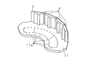
- FIG. 5 is a schematic perspective view showing the first yoke 11, the back yoke 3 and the support 6.
- the plurality of line segments in the side portion of the first yoke 11 are respectively connected to the lower side surface of the small diameter side of the back yoke 3 formed by connecting a plurality of flat plates in the longitudinal direction.
- the upper side surface of the back yoke 3 on the small diameter side is connected to a second yoke 21 described later.
- a plurality of columns 6, 6,... Supporting the second yoke 21 are provided along the back yoke 3.
- the upper surface on the small diameter side of the first yoke 11 is in contact with the lower surface of the first nonmagnetic plate 12.
- the first nonmagnetic plate 12 has a plate shape whose outer shape is an arc shape in plan view, and a nonmagnetic material such as austenitic stainless steel or aluminum is used.
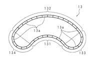
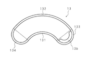
- FIG. 6 is a schematic plan view of the first magnet 13.
- the first magnet 13 includes a first small-diameter side arc portion 131, a first large-diameter side arc portion 132, a first one end side connecting arc portion 133, and a first other end side connecting arc portion 134.
- the first small-diameter side arc portion 131 and the first large-diameter side arc portion 132 are concentric circular arcs of 110 degrees, for example.
- the first one end side connecting arc part 133 has, for example, a semicircular arc shape, and connects the ends close to the second magnetic circuit side 30 of the first small diameter side arc part 131 and the first large diameter side arc part 132, respectively.
- the first other end side connecting arc part 134 has, for example, a semicircular arc shape, and connects the far end to the second magnetic circuit side 30 of each of the first small diameter side arc part 131 and the first large diameter side arc part 132.
- the 1st one end side connection arc part 133 and the 1st other end side connection arc part 134 do not necessarily need to be circular arc shape.
- the first small-diameter side arc portion 131 and the first large-diameter side arc portion 132 may be connected in a straight line, or may be V-shaped.
- the first magnet 13 is formed by arranging a plurality of first small magnets 13a, 13a,... Using a plurality of block-shaped ferrites or neodymium. Accordingly, the first magnet 13 has a circular arc shape in plan view, and no magnet is provided on the inner side from the inner side surface. With such a configuration, the first magnet 13 can suppress the difference in strength of the magnetic field in the gap.
- the upper surface of the first magnet 13 is a plate shape having a planar arc shape similar to that of the first nonmagnetic plate 12, and is in contact with the lower surface of the first resin plate 14 using, for example, a fluororesin or a phenol resin.
- the upper surface of the first resin plate 14 has a plate shape having a planar arc shape similar to that of the first nonmagnetic plate 12, and is in contact with the lower surface of the first magnetic pole piece 15 using, for example, a silicon steel plate or iron. ing.
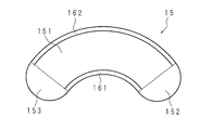
- FIG. 7 is a schematic plan view of the first magnetic pole piece 15.
- the first magnetic pole piece 15 includes a first central portion 151, a first one end portion 152, and a first other end portion 153.
- the first central portion is, for example, a portion having an arc shape of 110 °
- the first one end side end portion 152 is a semicircular portion including an end close to the second magnetic circuit side 30, and the first other end side.
- the end 153 is a semicircular portion including the end far from the second magnetic circuit side 30.
- a first small-diameter side protruding piece 161 is fixed to the outer edge of the first central portion 151 on the small-diameter side
- a first large-diameter side protruding piece 162 is fixed to the outer edge of the first central portion 151 on the large-diameter side.
- the first small diameter side protruding piece 161 has a larger amount of protrusion than the first large diameter side protruding piece 162.
- the first small-diameter side protruding piece 161 is provided on a part of the first magnetic pole piece 15 on the inner peripheral side
- the first large-diameter side protruding piece 162 is provided on a part of the first magnetic pole piece 15 on the large diameter side. It only has to be.
- the first small-diameter side protruding piece 161 may be provided only on a part of the first central portion 151 on the small-diameter side, and a part of the first small-diameter side protruding piece 161 is provided on the first one end side end 152 or the first other end side end 153. It may be provided. The same applies to the first large-diameter side protruding piece 162.
- the first nonmagnetic plate 12, the first magnet 13, the first resin plate 14, and the first magnetic pole piece 15 have substantially the same outer shape, and the area of the upper surface and the lower surface is smaller than that of the first yoke 11.
- the first yoke 11 may have any shape as long as the areas of the upper surface and the lower surface are larger than those of the first nonmagnetic plate 12, the first magnet 13, the first resin plate 14, and the first magnetic pole piece 15.
- the first yoke 11 has a first magnet 13 defined by a first small-diameter side arc portion 131, a first large-diameter side arc portion 132, a first one end side connecting arc portion 133, and a first other end side connecting arc portion 134.
- First screw holes 11a, 11a,... Are provided at positions similar to the arrangement.
- the first screw holes 11a, 11a,... are provided along a similar arc smaller than the inner surface of the first magnet 13, for example.
- the first magnetic pole 1 may partially have a strength different from the magnetic field strength planned at the time of design due to the influence of the use environment or the distortion of the first magnet 13. In this case, the magnetic field strength is partially adjusted by appropriately screwing the screw 17 into the one or more first screw holes 11a from the lower surface side of the first yoke 11.
- the first screw hole 11a may be a hole in which a screw is not cut. In this case, a rod-like object using a ferromagnetic material is inserted into the hole instead of the screw 17. Moreover, the hole which is not penetrated may be provided instead of the screw hole.
- the similar arc formed by the first screw holes 11 a, 11 a,... May be larger than the inner surface of the first magnet 13.
- FIG. 8 is an exploded perspective view of the second magnetic pole 2.
- the second magnetic pole 2 includes a second yoke 21, a second nonmagnetic plate 22, a second magnet 23, a second resin plate 24, a second magnetic pole piece 25, a second small diameter side protruding piece 261, 2 large-diameter side protruding pieces 262.
- the lower surface of the second yoke 21 made of, for example, a silicon steel plate or iron having a shape symmetrical to the first yoke 11 is supported by the support columns 6, 6.
- the plurality of line segments on the side portion of the second yoke 21 are respectively connected to the upper side surface on the small diameter side of the back yoke 3 formed by connecting a plurality of flat plates in the longitudinal direction.
- the lower surface of the second yoke 21 has a shape symmetrical to the first nonmagnetic plate 12 and is in contact with the upper surface of the second nonmagnetic plate 22 using a nonmagnetic material such as aluminum or austenitic stainless steel. .
- the lower surface of the second non-magnetic plate 22 is in contact with the upper surface of the second magnet 23 that is symmetrical with the first magnet 13.
- the second magnet 23 includes a second small-diameter side arc portion 231, a second large-diameter side arc portion 232, a second one end side connecting arc portion 233, and a second other end side connecting arc portion 234.
- the second small-diameter side arc portion 231 and the second large-diameter side arc portion 232 are concentric circular arcs of 110 degrees, for example.
- the second one end side connecting arc part 233 has, for example, a semicircular arc shape, and connects the ends of the second small diameter side arc part 231 and the second large diameter side arc part 232 close to the second magnetic circuit 30.
- the second other end side connecting arc portion 234 has, for example, a semicircular arc shape, and connects the far end to the second magnetic circuit 30 of each of the second small diameter side arc portion 231 and the second large diameter side arc portion 232.
- the second one end side connecting arc portion 233 and the second other end side connecting arc portion 234 do not necessarily have an arc shape.
- the second small end side arc portion 231 and the second large diameter side arc portion 232 are formed in a straight line. It may be tied or V-shaped. Similar to the first magnet 13, the second magnet 23 is formed by arranging small magnets using a plurality of block-shaped ferrites, neodymium, or the like.
- the lower surface of the second magnet 23 is in contact with the upper surface of a resin-made second resin plate 24 that is symmetrical with the first resin plate 14. Further, the lower surface of the second resin plate 24 is in contact with the upper surface of the second magnetic pole piece 25 made of, for example, a silicon steel plate or iron having a shape symmetrical to the first magnetic pole piece 15.
- a second small diameter side protruding piece 261 is fixed to the outer edge of the second central portion 251 on the small diameter side, and a second large diameter side protruding piece 262 is fixed to the outer edge of the second central portion 251 on the large diameter side, respectively. ing.
- the second small-diameter side protruding piece 261 and the second large-diameter side protruding piece 262 are made of silicon steel plate or iron, and protrude downward in the position where the first magnetic pole 1 is disposed.
- the second small diameter side protruding piece 261 has a larger amount of protrusion than the second large diameter side protruding piece 262.
- no protruding piece is provided on the second end-side end 252 and the second other-end end 253.
- the first small-diameter-side protruding piece 161 is opposed to the second small-diameter-side protruding piece 261, and the first large-diameter-side protruding piece 162 is opposed to the second large-diameter-side protruding piece 262, respectively.
- the second small-diameter side protruding piece 261 is provided on a part of the second magnetic pole piece 25 on the inner peripheral side
- the second large-diameter side protruding piece 262 is provided on a part of the second magnetic pole piece 25 on the large diameter side. It only has to be.
- the second small-diameter-side protruding piece 261 may be provided only on a part of the second central portion 251 on the small-diameter side, and a part of the second small-diameter-side protruding piece 261 is provided on the second one end side end 252 or the second other end side end 253. It may be provided. The same applies to the second large-diameter side protruding piece 262.
- the second non-magnetic plate 22, the second magnet 23, the second resin plate 24, and the second magnetic pole piece 25 have substantially the same outer shape, and the upper and lower surfaces are smaller than the second yoke 21.
- the shape of the second yoke 21 is not limited as long as the areas of the upper surface and the lower surface are larger than those of the second nonmagnetic plate 22, the second magnet 23, the second resin plate 24, and the second magnetic pole piece 25.
- the second yoke 21 includes a second magnet 23 defined by a second small-diameter side arc portion 231, a second large-diameter side arc portion 232, a second one end side connecting arc portion 233, and a second other end side connecting arc portion 234.
- Second screw holes 21a, 21a,... Penetrating at positions similar to the arrangement are provided.
- the second screw holes 21a, 21a,... Are provided along a similar arc smaller than the inner surface of the second magnet 23, for example.
- FIG. 9 is a graph showing the magnetic field strength in the first magnetic circuit 10.
- the horizontal axis represents the rotation angle (°) from the predetermined position of the rotary shaft 43, and the vertical axis represents the magnetic field strength (mT).
- the broken lines indicate the magnetic field strength when the protruding pieces are provided on the entire periphery of the first magnetic pole piece 15 and the second magnetic pole piece 25.
- the first small diameter side protruding piece 161 and the first large diameter side protruding piece 162 are connected at the periphery of the first magnetic pole piece 15, and the second small diameter side protruding piece 261 and the second large diameter side protruding piece 262 are connected to each other.
- the solid line indicates the magnetic field strength in the case of the present embodiment.
- the first small-diameter side protruding piece 161 and the first large-diameter side protruding piece 162 are provided only in the first center portion 151, and the second small-diameter side protruding piece 261 and the second large-diameter side protruding piece 262 are the second center. Only the part 251 is provided.
- the first small-diameter side protruding piece 161 and the first large-diameter side protruding piece 162 are provided only at the periphery of the first central portion 151, and the second small-diameter side protruding piece 261 and the second large-diameter side protruding piece 262 are the second central portion.
- the uniform magnetic field space can be widened.
- one or both of the first nonmagnetic plate 12 and the second nonmagnetic plate 22 can be replaced with nonmagnetic plates having different thicknesses.
- the first magnetic circuit 10 can apply a magnetic field for a long time.
- FIG. 10 is a schematic perspective view showing the back yoke 3.
- the back yoke 3 according to the present embodiment is thicker at one end side, which is closer to the second magnetic circuit 30, than at the other end side.
- the flat plates 3 a to 3 d constituting the back yoke 3 are configured to increase in thickness as they are closer to the second magnetic circuit 30. That is, the thickness of each flat plate constituting the back yoke 3 increases in the order of the flat plates 3a, 3b, 3c, and 3d.
- the magnetic field generated by the second magnetic circuit 30 is stronger than the magnetic field generated by the first magnetic circuit 10.
- the uniform magnetic field space formed by the first magnetic circuit 10 may be damaged by the influence of the magnetic field leaking from the second magnetic circuit 30.
- the influence of the magnetic field leaking from the second magnetic circuit 30 can be suppressed by thickening the end on the one end side of the back yoke 3.
- the back yoke 3 may be composed of one or a plurality of curved plates.
- FIG. 11 is a schematic perspective view showing another example of the back yoke 3.
- the back yoke 3 is configured by a single curved plate, and the back yoke 3 is configured to be thicker as it is closer to the second magnetic circuit 30.
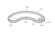
- FIG. 12 is a schematic plan view showing an example in which the first auxiliary magnet 13 b is provided on the first magnet 13.
- the first auxiliary magnet 13 b is fixed to the inside of the first one end side connecting arc portion 133.
- the first auxiliary magnet 13b plays a role of increasing the magnetic field strength at the end of the first magnetic circuit 10 on the second magnetic circuit 30 side, and assisting the homogenization of the magnetic field in the predetermined space.
- an auxiliary magnet fixed to the second one end side connecting arc portion 233 may be provided on the second magnet 23.
- the first auxiliary magnet 13b is a schematic perspective view showing another example in which the first auxiliary magnet 13 b is provided on the first magnet 13.
- the first auxiliary magnet 13b does not need to be fixed to the first one end side connecting arc part 133, and may be attached to the first magnet 13 in a form of being placed on the first nonmagnetic plate 12 on one end side, for example. .
- the first auxiliary magnet 13b can increase the magnetic field strength at the end on the second magnetic circuit 30 side, the influence of the magnetic field by the second magnetic circuit 30 described above can be suppressed. .
Landscapes
- Physics & Mathematics (AREA)
- Condensed Matter Physics & Semiconductors (AREA)
- General Physics & Mathematics (AREA)
- Electromagnetism (AREA)
- Engineering & Computer Science (AREA)
- Power Engineering (AREA)
- Magnetic Resonance Imaging Apparatus (AREA)
Abstract
Priority Applications (3)
| Application Number | Priority Date | Filing Date | Title |
|---|---|---|---|
| US14/409,181 US9576712B2 (en) | 2012-07-02 | 2013-06-26 | Magnetic circuit for magnetic field generator |
| EP13812934.1A EP2868271A4 (fr) | 2012-07-02 | 2013-06-26 | Circuit magnétique |
| JP2014523692A JP5892246B2 (ja) | 2012-07-02 | 2013-06-26 | 磁気回路 |
Applications Claiming Priority (2)
| Application Number | Priority Date | Filing Date | Title |
|---|---|---|---|
| JP2012-148864 | 2012-07-02 | ||
| JP2012148864 | 2012-07-02 |
Publications (1)
| Publication Number | Publication Date |
|---|---|
| WO2014007122A1 true WO2014007122A1 (fr) | 2014-01-09 |
Family
ID=49881879
Family Applications (1)
| Application Number | Title | Priority Date | Filing Date |
|---|---|---|---|
| PCT/JP2013/067505 WO2014007122A1 (fr) | 2012-07-02 | 2013-06-26 | Circuit magnétique |
Country Status (4)
| Country | Link |
|---|---|
| US (1) | US9576712B2 (fr) |
| EP (1) | EP2868271A4 (fr) |
| JP (1) | JP5892246B2 (fr) |
| WO (1) | WO2014007122A1 (fr) |
Cited By (1)
| Publication number | Priority date | Publication date | Assignee | Title |
|---|---|---|---|---|
| WO2016061876A1 (fr) * | 2014-10-24 | 2016-04-28 | 广东电网有限责任公司东莞供电局 | Capteur de résonance magnétique nucléaire à un seul côté en arc de cercle |
Families Citing this family (2)
| Publication number | Priority date | Publication date | Assignee | Title |
|---|---|---|---|---|
| EP2869078A4 (fr) * | 2012-07-02 | 2016-06-15 | Dispositif d'application de champ magnétique | |
| US10970614B2 (en) * | 2018-06-21 | 2021-04-06 | Rosemount Inc. | Single-use pressure transducer disposable interface |
Citations (7)
| Publication number | Priority date | Publication date | Assignee | Title |
|---|---|---|---|---|
| JPS6182607U (fr) * | 1984-11-06 | 1986-05-31 | ||
| JP2001076925A (ja) * | 1999-08-31 | 2001-03-23 | Hitachi Metals Ltd | 平面多極異方性を有する永久磁石およびアクチュエータ |
| JP2002502648A (ja) * | 1998-02-09 | 2002-01-29 | オーディン・メディカル・テクノロジーズ・リミテッド | Mri又はmrtプローブで使用するための開いた磁石及び開いた磁気装置を設計するための方法 |
| JP2006204551A (ja) | 2005-01-28 | 2006-08-10 | Kyushu Univ | 生体計測装置及びその方法 |
| WO2008007771A1 (fr) * | 2006-07-13 | 2008-01-17 | Hitachi Metals, Ltd. | Procédé de réglage de champ magnétique et générateur de champ magnétique |
| JP2010227247A (ja) | 2009-03-26 | 2010-10-14 | Kyushu Univ | 計測装置および計測方法 |
| JP2011527222A (ja) * | 2008-07-08 | 2011-10-27 | 国立大学法人九州大学 | 計測装置及び計測方法 |
Family Cites Families (10)
| Publication number | Priority date | Publication date | Assignee | Title |
|---|---|---|---|---|
| EP0161782B1 (fr) * | 1984-04-11 | 1988-11-09 | Sumitomo Special Metal Co., Ltd. | Dispositif pour la génération d'un champ magnétique pour NMR-CT |
| EP0998876B1 (fr) * | 1998-04-14 | 2007-12-12 | Hitachi Metals, Limited | Generateur de champ magnetique pour irm |
| EP1004270B1 (fr) * | 1998-06-19 | 2007-04-04 | Neomax Co., Ltd. | Generateur de champ magnetique pour irm |
| WO2001055732A2 (fr) * | 2000-01-25 | 2001-08-02 | Uri Rapoport | Mecanismes de reglage du champ et procedes permettant l'agencement d'un aimant permanent au moyen d'une plaque d'appui |
| WO2003068066A1 (fr) * | 2002-02-15 | 2003-08-21 | Sumitomo Special Metals Co., Ltd. | Generateur de champ magnetique et son procede de fabrication |
| US6946941B2 (en) | 2003-08-29 | 2005-09-20 | Astronautics Corporation Of America | Permanent magnet assembly |
| JP4090971B2 (ja) * | 2003-09-10 | 2008-05-28 | 信越化学工業株式会社 | 磁気回路 |
| CN1985339B (zh) * | 2004-02-03 | 2010-12-08 | 美国宇航公司 | 永磁体组件 |
| WO2006038261A1 (fr) * | 2004-09-30 | 2006-04-13 | Neomax Co., Ltd. | Generateur de champ magnétique pour mri |
| FR2958443B1 (fr) * | 2010-03-31 | 2012-10-05 | Cooltech Applications | Generateur de champ magnetique et dispositif thermique magnetocalorique comportant ledit generateur de champ magnetique. |
-
2013
- 2013-06-26 US US14/409,181 patent/US9576712B2/en not_active Expired - Fee Related
- 2013-06-26 WO PCT/JP2013/067505 patent/WO2014007122A1/fr active Application Filing
- 2013-06-26 JP JP2014523692A patent/JP5892246B2/ja active Active
- 2013-06-26 EP EP13812934.1A patent/EP2868271A4/fr not_active Withdrawn
Patent Citations (7)
| Publication number | Priority date | Publication date | Assignee | Title |
|---|---|---|---|---|
| JPS6182607U (fr) * | 1984-11-06 | 1986-05-31 | ||
| JP2002502648A (ja) * | 1998-02-09 | 2002-01-29 | オーディン・メディカル・テクノロジーズ・リミテッド | Mri又はmrtプローブで使用するための開いた磁石及び開いた磁気装置を設計するための方法 |
| JP2001076925A (ja) * | 1999-08-31 | 2001-03-23 | Hitachi Metals Ltd | 平面多極異方性を有する永久磁石およびアクチュエータ |
| JP2006204551A (ja) | 2005-01-28 | 2006-08-10 | Kyushu Univ | 生体計測装置及びその方法 |
| WO2008007771A1 (fr) * | 2006-07-13 | 2008-01-17 | Hitachi Metals, Ltd. | Procédé de réglage de champ magnétique et générateur de champ magnétique |
| JP2011527222A (ja) * | 2008-07-08 | 2011-10-27 | 国立大学法人九州大学 | 計測装置及び計測方法 |
| JP2010227247A (ja) | 2009-03-26 | 2010-10-14 | Kyushu Univ | 計測装置および計測方法 |
Non-Patent Citations (1)
| Title |
|---|
| See also references of EP2868271A4 |
Cited By (1)
| Publication number | Priority date | Publication date | Assignee | Title |
|---|---|---|---|---|
| WO2016061876A1 (fr) * | 2014-10-24 | 2016-04-28 | 广东电网有限责任公司东莞供电局 | Capteur de résonance magnétique nucléaire à un seul côté en arc de cercle |
Also Published As
| Publication number | Publication date |
|---|---|
| JP5892246B2 (ja) | 2016-03-23 |
| EP2868271A4 (fr) | 2016-05-18 |
| US20150137922A1 (en) | 2015-05-21 |
| US9576712B2 (en) | 2017-02-21 |
| JPWO2014007122A1 (ja) | 2016-06-02 |
| EP2868271A1 (fr) | 2015-05-06 |
Similar Documents
| Publication | Publication Date | Title |
|---|---|---|
| US20090072939A1 (en) | Magnet system and mri apparatus | |
| RU2012110609A (ru) | Устройство и способ генерации и перемещения магнитного поля, имеющего линию отсутствия поля | |
| JP2011503541A5 (fr) | ||
| JP5892246B2 (ja) | 磁気回路 | |
| WO2009155700A8 (fr) | Système de radiothérapie | |
| MY153308A (en) | Calibratable multidimensional magnetic point sensor | |
| US9664757B2 (en) | Coil device and magnetic resonance imaging apparatus | |
| JP2000070238A (ja) | 磁気共鳴システム | |
| JP2005118098A (ja) | 磁気共鳴イメージング装置 | |
| JP5866720B2 (ja) | 磁場印加装置 | |
| JP2006006936A (ja) | 磁界生成装置及びそのシミング方法 | |
| Antoniou et al. | Challenges regarding MR compatibility of an MRgFUS robotic system | |
| TWM324205U (en) | Single-sided portable NMR apparatus | |
| US20190162801A1 (en) | Method for modifying and controlling magnetic field and apparatus for the same | |
| JP6268325B1 (ja) | 磁性体定量装置及びその製造方法 | |
| JP2008108763A (ja) | 着磁装置および着磁方法 | |
| Chang et al. | Simple mobile single-sided NMR apparatus with a relatively homogeneous B0 distribution | |
| Araujo et al. | Characterization of magnetic nanoparticles by a modular Hall magnetometer | |
| JP2005147693A (ja) | 電子スピン共鳴状態測定装置および測定方法 | |
| JP6840398B2 (ja) | 磁場印加装置 | |
| Zhu et al. | High spatial resolution NMR imaging of polymer layers on metallic substrates | |
| RU2584720C1 (ru) | Способ измерения магнитного поля | |
| US11105874B2 (en) | Magnetic resonance unit and method for compensating for basic magnetic field inhomogeneities of the first order in an examination region of the magnetic resonance unit | |
| JPH04117943A (ja) | 磁気共鳴影像装置 | |
| JP2003116812A5 (fr) |
Legal Events
| Date | Code | Title | Description |
|---|---|---|---|
| 121 | Ep: the epo has been informed by wipo that ep was designated in this application |
Ref document number: 13812934 Country of ref document: EP Kind code of ref document: A1 |
|
| WWE | Wipo information: entry into national phase |
Ref document number: 14409181 Country of ref document: US |
|
| ENP | Entry into the national phase |
Ref document number: 2014523692 Country of ref document: JP Kind code of ref document: A |
|
| NENP | Non-entry into the national phase |
Ref country code: DE |
|
| WWE | Wipo information: entry into national phase |
Ref document number: 2013812934 Country of ref document: EP |