WO2014006998A1 - 溶接方法 - Google Patents
溶接方法 Download PDFInfo
- Publication number
- WO2014006998A1 WO2014006998A1 PCT/JP2013/064499 JP2013064499W WO2014006998A1 WO 2014006998 A1 WO2014006998 A1 WO 2014006998A1 JP 2013064499 W JP2013064499 W JP 2013064499W WO 2014006998 A1 WO2014006998 A1 WO 2014006998A1
- Authority
- WO
- WIPO (PCT)
- Prior art keywords
- groove
- welding
- members
- arc
- filler wire
- Prior art date
- Legal status (The legal status is an assumption and is not a legal conclusion. Google has not performed a legal analysis and makes no representation as to the accuracy of the status listed.)
- Ceased
Links
Images



Classifications
-
- B—PERFORMING OPERATIONS; TRANSPORTING
- B23—MACHINE TOOLS; METAL-WORKING NOT OTHERWISE PROVIDED FOR
- B23K—SOLDERING OR UNSOLDERING; WELDING; CLADDING OR PLATING BY SOLDERING OR WELDING; CUTTING BY APPLYING HEAT LOCALLY, e.g. FLAME CUTTING; WORKING BY LASER BEAM
- B23K9/00—Arc welding or cutting
- B23K9/02—Seam welding; Backing means; Inserts
- B23K9/0213—Narrow gap welding
-
- B—PERFORMING OPERATIONS; TRANSPORTING
- B23—MACHINE TOOLS; METAL-WORKING NOT OTHERWISE PROVIDED FOR
- B23K—SOLDERING OR UNSOLDERING; WELDING; CLADDING OR PLATING BY SOLDERING OR WELDING; CUTTING BY APPLYING HEAT LOCALLY, e.g. FLAME CUTTING; WORKING BY LASER BEAM
- B23K9/00—Arc welding or cutting
- B23K9/16—Arc welding or cutting making use of shielding gas
- B23K9/173—Arc welding or cutting making use of shielding gas and of a consumable electrode
- B23K9/1735—Arc welding or cutting making use of shielding gas and of a consumable electrode making use of several electrodes
Definitions
- the present invention relates to a welding method for welding a pair of members.
- arc welding is performed to join a pair of members.
- Arc welding for example, welds a pair of members by melting the joint and electrodes of the pair of members by an arc generated between the joint of the pair of members and an electrode such as a welding wire. is there.
- the groove of the pair of members is used as a Y groove formed in a groove having a Y-shaped cross section (see, for example, Patent Document 1). ).
- the groove is a Y groove
- the groove width of the Y groove is widened, so that the thermal distortion (thermal shrinkage) of the surplus formed by arc welding increases.
- the positional relationship between the members varies.
- the groove spreads toward the surface of the member the variation in the positional relationship between the members further increases.
- the groove is a Y groove
- the groove area increases, and the amount of heat input to each member increases.
- the influence of thermal strain (heat shrinkage) on the vicinity of the welded portion increases.
- thermal strain heat shrinkage
- the bearing mechanism is distorted by the heat of welding, and the function as the bearing mechanism is greatly reduced.
- a member having a large influence of thermal strain needs to be assembled in the vicinity of the welded portion after welding, it is a factor that hinders reduction in man-hours.
- an object of one aspect of the present invention is to provide a welding method capable of suppressing the influence of heat.
- a welding method is a welding method for welding a pair of members, a groove forming step of forming a groove-shaped groove in the pair of members, and a pair of members along the groove.
- a welding step for welding, and in the groove forming step, the groove is a narrow groove having a substantially U-shaped cross section in which the opposing surfaces are substantially parallel.
- the groove width of the groove is narrower than that of the Y groove by setting the groove to be a narrow groove. (Heat shrinkage) is reduced. Thereby, since the deterioration of the balance of the heat shrink along a welding surface can be suppressed, the fluctuation
- the narrow groove is formed in a substantially U-shaped cross section in which the opposing surfaces are substantially parallel, fluctuations in the positional relationship between the members can be further suppressed. Further, since the narrow groove has a groove area smaller than that of the Y groove, the amount of heat input to each member is small. For this reason, the influence of the thermal strain (heat shrinkage) in the vicinity of the welded portion can be suppressed.
- the distance between the pair of members in the narrow groove may be 5 mm or more and 15 mm or less.
- the depth of the narrow groove may be 2.5 mm or more and 15 mm or less.
- a molten portion is formed in a groove by an arc generated by energizing an electrode, and a subsequent wire is supplied to the molten portion without being energized before the molten portion is cured. May be.
- the trailing wire may be supplied to the rising portion of the melting portion at the rear of the arc traveling direction.
- the trailing wire can be prevented from being directly heated by the arc, so that the cooling effect of the melting portion can be increased, and the trailing wire is supplied before the melting portion is cooled and hardened. Therefore, it is possible to suppress the insufficient formation of the surplus.
- FIG. 1 is a diagram conceptually showing a welding apparatus.
- the welding apparatus 1 is a welding apparatus for performing cold tandem welding, and includes an arc welding torch 2, a filler wire supply device 3, and a connecting member 4.
- the cold tandem welding will be described later.
- the arc welding torch 2 performs arc welding.
- the arc welding torch 2 sends out a welding wire 6 as a consumable electrode sent out from the first wire sending device 5 to a welding position P1 of the base material.
- the arc welding torch 2 energizes the welding wire 6 with the welding current supplied from the power supply device 7 to generate an arc between the welding wire 6 and the base material.
- the welding wire 6 for example, a solid wire conforming to JIS Z3312 YGW12 can be used.
- the filler wire supply device 3 sends the filler wire 9 sent from the second wire sending device 8 to the position P2 close to the welding position P1 of the base material without energization.
- the filler wire 9 for example, a solid wire conforming to JIS Z3312 YGW12 can be used.
- the connecting member 4 maintains the distance between the arc welding torch 2 and the filler wire supply device 3 so that the position P1 and the position P2 are at a predetermined distance, and the arc welding torch 2 and the filler wire supply device 3 Is a device for connecting the two.
- the connecting member 4 may connect the arc welding torch 2 and the filler wire supply device 3 in a detachable manner, or may connect the arc welding torch 2 and the filler wire supply device 3 fixedly.
- the connection member 4 may fix the space
- the welding device 1 configured as described above is configured such that when the arc welding torch 2 and the filler wire supply device 3 connected to the connecting member 4 move relative to the base material, the filler wire A supply device 3 is disposed behind the arc welding torch 2. For this reason, the position P2 is behind the position P1 in the movement direction.
- the direction in which the arc welding torch 2 and the filler wire supply device 3 move relative to the base material is referred to as “traveling direction”.
- a groove forming step is performed in which a groove-shaped groove is formed at a joint portion of a pair of members.
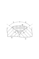
- FIG. 2 is a cross-sectional view showing the groove formed by the groove forming step.
- the one member 10 (base material) to be joined and the other member 11 (base material) are abutted, and a groove shape is formed at a portion where the one member 10 and the other member 11 are joined. This is done by forming a narrow groove 12.
- the narrow groove 12 is formed in a substantially U-shaped cross section in which the opposed surfaces are substantially parallel. That is, the narrow groove 12 is defined by the one member facing surface 10a facing the other member 11 of the one member 10 and the other member facing surface 11b facing the one member 10 of the other member 11. The one member facing surface 10a and the other member facing surface 11b are substantially parallel.
- the shape of the bottom surface of the narrow groove 12 is not particularly limited, and may be flat or curved.
- the separation distance A between the one member facing surface 10a and the other member facing surface 11b in the narrow groove 12 is not particularly limited, but may be 5 mm or more and 15 mm or less.
- the depth of the narrow groove 12 is not particularly limited, but can be 2.5 mm or more and 15 mm or less.
- a welding process is performed in which a pair of members are arc welded along the narrow groove.
- Cold tandem welding is a welding method using two wires, a leading welding wire and a trailing filler wire, in which a molten portion is formed in the groove by an arc generated by energizing the preceding welding wire. This is a welding method in which the subsequent filler wire is supplied to the molten portion without energization before the portion is cured.
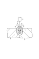
- FIG. 3 is a diagram for explaining the welding process.
- the arc welding torch 2 and the filler wire supply device 3 are moved relative to the one member 10 and the other member 11 as the base material along the narrow groove 12. .
- the arc welding torch 2 moves ahead of the filler wire supply device 3, and the filler wire supply device 3 moves behind the arc welding torch.
- the melting part 14 is constituted by a molten pool.
- the melted portion 14 is dug down under the arc 13 by receiving pressure (arc force) from the arc 13, and the portion dug up most by the arc force becomes the bottom 14 a of the melted portion 14. Further, as the melting portion 14 moves away from the bottom portion 14a, the influence of the arc force is weakened and gradually rises and rises. For this reason, the rising part 14b where the fusion
- the raised portion 14b is a portion made of molten metal before being hardened (solidified). Then, the raised portion 14 b is cooled and hardened (solidified), so that the surplus 15 is formed between the one member 10 and the other member 11. In addition, this surplus 15 is also called a bead.
- the filler wire 9 is supplied from the filler wire supply device 3 following the arc welding torch 2 to the rising portion 14b of the melting portion 14 without energization.
- the supply position of the filler wire 9 can be adjusted, for example, by adjusting the distance between the arc welding torch 2 and the filler wire supply device 3 by the connecting member 4 or adjusting the direction of the filler wire supply device 3.
- the filler wire 9 When the filler wire 9 is supplied to the rising part 14b of the melting part 14, the filler wire 9 is melted by the heat of the melting part 14, and the molten metal is replenished to the melting part 14. As a result, a good surplus 15 is formed.
- the filler wire 9 that is not energized is not heated, when the filler wire 9 is supplied to the rising portion 14b of the melting portion 14, the heat of the melting portion 14 is taken away by the filler wire 9, and the melting portion 14 is cooled.
- FIG. 4 is a view showing a state where a Y groove is formed and normal welding is performed.
- FIG. 5 is a diagram showing a state where a narrow groove is formed and normal welding is performed.
- FIG. 6 is a view showing a state where a narrow groove is formed and cold tandem welding is performed.
- the groove spreads toward the surfaces of the one member 10 and the other member 11.
- the shrinkage range D of the melting part 14 is widened. For this reason, when the melting part 14 is cooled and hardened, the melting part 14 contracts greatly. As a result, the positional relationship between the one member 10 and the other member 11 varies greatly, and a large internal stress is generated.
- the Y groove has a large groove area, the amount of heat input from the melted portion 14 to the one member 10 and the other member 11 increases.
- the shrinkage range D of the fusion zone 14 is Y open. It becomes narrower than before. For this reason, when the fusion
- the narrow groove has a groove area smaller than that of the Y groove, the amount of heat input from the melting portion 14 to the one member 10 and the other member 11 is suppressed to be smaller than that in the case of the Y groove.
- the influence of heat can be suppressed and the amount of heat input to the one member 10 and the other member 11 by making the groove narrow. Can be reduced.
- the molten portion 14 can be cooled by the cold filler wire 9, so that the amount of heat input to the one member 10 and the other member 11 can be significantly reduced. it can. Accordingly, for example, even if welding is performed after a member having a large influence of thermal strain is assembled in the vicinity of the welded portion, the influence of the thermal strain on the member can be suppressed, so that the welding process is reduced. be able to.
- the filler wire 9 that is not energized is not heated, the melted portion 16 is cooled by supplying the filler wire 9 that is not energized to the melting portion 16 before being cured, and the amount of heat input to each member Can be further reduced. For this reason, even if it welds after attaching the member with the big influence of a thermal strain in the vicinity of a welding part, the influence of the thermal strain to the said member can be suppressed. Thereby, reduction of a welding process can be aimed at. Moreover, since the heat shrinkage is remarkably suppressed in the portion to which the filler wire 9 is supplied, the substantial heat shrinkage range of the melting part 16 is narrowed.
- melting part 16 carrying out cooling hardening is suppressed significantly, the fluctuation
- the molten metal is replenished to the melting part 16, so that a good surplus 15 can be formed and the occurrence of poor welding such as humping can be suppressed. Can do.
- the separation distance A between the one member facing surface 10a and the other member facing surface 11b in the narrow groove 12 is set to 5 mm or more and 15 mm or less, it is possible to suppress the influence of thermal strain while ensuring workability. .
- the depth of the narrow groove 12 is set to 2.5 mm or more and 15 mm or less, it is possible to suppress the influence of thermal strain while ensuring the bonding strength.
- the said embodiment demonstrated as what supplies the filler wire 9 to the swelling part 14b of the fusion
- the welding apparatus has been specifically described.
- the welding apparatus is not limited to the above-described one.
- JP 2008-055506 A, JP 2011-224586 A, and the like. Can be used.
Landscapes
- Engineering & Computer Science (AREA)
- Physics & Mathematics (AREA)
- Plasma & Fusion (AREA)
- Mechanical Engineering (AREA)
- Arc Welding In General (AREA)
Abstract
一対の部材を溶接する溶接方法であって、一対の部材に溝状の開先を形成する開先形成工程と、開先に沿って一対の部材を溶接する溶接工程と、を有し、開先形成工程では、開先を、対向面が略平行となる断面略U字状の狭開先とする、溶接方法。
Description
本発明は、一対の部材を溶接する溶接方法に関する。
一般的に、一対の部材を接合するために、アーク溶接が行われている。アーク溶接は、例えば、一対の部材の接合部と溶接ワイヤなどの電極との間に発生させたアークにより、一対の部材の接合部及び電極を溶融させることで、一対の部材を溶接するものである。そして、このようなアーク溶接を行い易くするために、一対の部材の開先を、断面Y字状の溝に形成されたY開先とすることが行われている(例えば、特許文献1参照)。
しかしながら、開先をY開先とすると、Y開先の溝幅が広くなるため、アーク溶接により形成される余盛の熱歪(熱収縮)が大きくなる。これにより、溶接面に沿った熱収縮のバランスが悪くなるため、部材間の位置関係が変動する。しかも、開先が部材の表面に向けて広がっているため、部材間の位置関係の変動が更に増大する。
また、開先をY開先とすると、開先面積が大きくなるため、各部材への入熱量が大きくなる。その結果、溶接部の近傍への熱歪(熱収縮)の影響が大きくなる。例えば、ベアリング機構を溶接部の近傍に組み付けた状態で溶接を行うと、ベアリング機構は、溶接の熱によって歪んでしまい、ベアリング機構としての機能が大きく低下する。このため、熱歪の影響が大きい部材は、溶接を行った後に溶接部の近傍に組み付ける必要があるため、工数の削減を阻害する要因となっている。
そこで、本発明の一側面は、熱の影響を抑制することができる溶接方法を提供することを目的とする。
本発明の一側面に係る溶接方法は、一対の部材を溶接する溶接方法であって、一対の部材に溝状の開先を形成する開先形成工程と、開先に沿って一対の部材を溶接する溶接工程と、を有し、開先形成工程では、開先を、対向面が略平行となる断面略U字状の狭開先とする。
本発明の一側面に係る溶接方法によれば、開先を狭開先とすることで、Y開先よりも開先の溝幅が狭くなるため、溶接により形成される余盛の熱歪(熱収縮)が小さくなる。これにより、溶接面に沿った熱収縮のバランスの悪化を抑制することができるため、部材間の位置関係の変動を抑制することができる。しかも、この狭開先は、対向面が略平行となる断面略U字状に形成されているため、部材間の位置関係の変動を更に抑制することができる。また、狭開先はY開先よりも開先面積が小さいため、各部材への入熱量が小さくなる。このため、溶接部の近傍における熱歪(熱収縮)の影響を抑制することができる。
この場合、狭開先における一対の部材の離間距離は、5mm以上15mm以下としてもよい。
また、狭開先の深さは、2.5mm以上15mm以下としてもよい。
本発明の一側面の溶接工程は、電極を通電して発生させたアークにより開先に溶融部を形成し、溶融部が硬化する前に、後行ワイヤを通電せずに溶融部に供給してもよい。
この場合、後行ワイヤを、アークの進行方向後方における溶融部の盛り上がり部に供給してもよい。これにより、後行ワイヤがアークにより直接的に加熱されるのを抑制することができるため、溶融部の冷却効果を高めることができ、また、溶融部が冷却硬化する前に後行ワイヤを供給することができるため、余盛の形成不足を抑制することができる。
本発明の一側面によれば、熱の影響を抑制することができる溶接方法を提供することができる。
以下、本発明の一側面の好適な実施形態について、図面を参照して詳細に説明する。本実施形態は、本発明の一側面に係る溶接方法を、コールドタンデム溶接に適用したものである。なお、以下の説明において同一又は相当要素には同一符号を付し、重複する説明を省略する。
まず、本実施形態に係る溶接方法を説明する前に、溶接に用いる溶接装置について説明する。
図1は、溶接装置を概念的に示す図である。図1に示すように、溶接装置1は、コールドタンデム溶接を行うための溶接装置であり、アーク溶接用トーチ2と、フィラーワイヤ供給装置3と、連結部材4と、を備えている。なお、コールドタンデム溶接については後述する。
アーク溶接用トーチ2は、アーク溶接を行うものである。このアーク溶接用トーチ2は、第一ワイヤ送出装置5から送り出された消耗電極としての溶接ワイヤ6を母材の溶接位置P1に送り出す。また、アーク溶接用トーチ2は、電源供給装置7から供給された溶接電流を溶接ワイヤ6に通電して、この溶接ワイヤ6と母材との間にアークを発生させる。溶接ワイヤ6としては、例えば、JIS Z3312 YGW12に準拠するソリッドワイヤを用いることができる。
フィラーワイヤ供給装置3は、第二ワイヤ送出装置8から送り出されたフィラーワイヤ9を、通電することなく、母材の溶接位置P1から近接した位置P2に送り出すものである。フィラーワイヤ9としては、例えば、JIS Z3312 YGW12に準拠するソリッドワイヤを用いることができる。
連結部材4は、位置P1と位置P2とが所定の距離となるようにアーク溶接用トーチ2とフィラーワイヤ供給装置3との間隔を維持しつつ、アーク溶接用トーチ2とフィラーワイヤ供給装置3とを連結する装置である。連結部材4は、アーク溶接用トーチ2とフィラーワイヤ供給装置3とを脱着可能に連結してもよく、アーク溶接用トーチ2とフィラーワイヤ供給装置3とを固定的に連結してもよい。また、連結部材4は、アーク溶接用トーチ2とフィラーワイヤ供給装置3との間隔を固定としてもよく、アーク溶接用トーチ2とフィラーワイヤ供給装置3との間隔を可変としてもよい。
このように構成される溶接装置1は、連結部材4に連結されたアーク溶接用トーチ2及びフィラーワイヤ供給装置3が母材に対して相対的に移動する際に、当該移動方向において、フィラーワイヤ供給装置3がアーク溶接用トーチ2の後方に配置される。このため、位置P2は、当該移動方向において、位置P1の後方となる。本実施形態では、アーク溶接用トーチ2及びフィラーワイヤ供給装置3が母材に対して相対的に移動する方向を、「進行方向」という。
次に、本実施形態に係る溶接方法について説明する。
本実施形態に係る溶接方法は、まず、一対の部材の接合部に溝状の開先を形成する開先形成工程を行う。
図2を参照して、開先形成工程について詳しく説明する。図2は、開先形成工程により形成した開先を示す断面図である。図2に示すように、開先形成工程では、接合する一方部材10(母材)と他方部材11(母材)とを突き合わせ、一方部材10と他方部材11とが接合する部分に、溝状の狭開先12を形成することにより行う。
狭開先12は、対向面が略平行となる断面略U字状に形成されている。つまり、狭開先12は、一方部材10の他方部材11に対向する一方部材対向面10aと、他方部材11の一方部材10に対向する他方部材対向面11bと、により画成されるものであり、一方部材対向面10aと他方部材対向面11bとが略平行になっている。なお、狭開先12の底面の形状は特に限定されるものではなく、平面状であってもよく、曲面状であってもよい。
狭開先12における一方部材対向面10aと他方部材対向面11bとの離間距離Aは、特に限定されるものではないが、5mm以上15mm以下とすることができる。
狭開先12の深さは、特に限定されるものではないが、2.5mm以上15mm以下とすることができる。
開先形成工程が終了すると、次に、狭開先に沿って一対の部材をアーク溶接する溶接工程を行う。
溶接工程では、コールドタンデム溶接を行う。コールドタンデム溶接は、先行溶接ワイヤ及び後行フィラーワイヤの2本のワイヤを用いた溶接方法であって、先行溶接ワイヤを通電して発生させたアークにより開先に溶融部を形成し、この溶融部が硬化する前に後行フィラーワイヤを通電せずに溶融部に供給する溶接方法である。
図3を参照して、溶接工程について詳しく説明する。図3は、溶接工程を説明するための図である。図3に示すように、溶接工程では、狭開先12に沿って、アーク溶接用トーチ2及びフィラーワイヤ供給装置3を母材となる一方部材10及び他方部材11に対して相対的に移動させる。すると、アーク溶接用トーチ2は、フィラーワイヤ供給装置3に先行して移動し、フィラーワイヤ供給装置3は、アーク溶接用トーチに後行して移動する。
このとき、フィラーワイヤ供給装置3に先行するアーク溶接用トーチ2において、溶接ワイヤ6に溶接電流を通電し、溶接ワイヤ6と狭開先12との間にアーク13を発生させる。すると、狭開先12に、溶接ワイヤ6、一方部材10及び他方部材11が溶融した溶融部14が形成される。
溶融部14は、溶融池により構成されている。この溶融部14は、アーク13の下方において、アーク13からの圧力(アーク力)を受けて掘り下げられており、アーク力により最も掘り下げられた部分が溶融部14の底部14aとなる。また、溶融部14は、底部14aから遠ざかるに従いアーク力の影響が弱まり、次第に上昇して盛り上がる。このため、底部14aの進行方向後方に、溶融部14が盛り上がった盛り上がり部14bが形成される。なお、盛り上がり部14bは、硬化(凝固)される前の溶融金属で構成される部分である。そして、盛り上がり部14bが冷却硬化(凝固)されることで、一方部材10と他方部材11との間に余盛15が形成される。なお、この余盛15は、ビードともいう。
一方、アーク溶接用トーチ2に後行するフィラーワイヤ供給装置3から、フィラーワイヤ9を通電せずに溶融部14の盛り上がり部14bに供給する。フィラーワイヤ9の供給位置の調整は、例えば、連結部材4によるアーク溶接用トーチ2とフィラーワイヤ供給装置3との間隔の調整や、フィラーワイヤ供給装置3の向きの調整などにより行うことができる。
フィラーワイヤ9を溶融部14の盛り上がり部14bに供給すると、フィラーワイヤ9が溶融部14の熱により溶融され、溶融部14に溶融金属が補充される。これにより、良好な余盛15が形成される。
また、通電されていないフィラーワイヤ9は加熱されていないため、フィラーワイヤ9を溶融部14の盛り上がり部14bに供給すると、溶融部14の熱がフィラーワイヤ9に奪われ、溶融部14が冷却される。
ここで、開先をY開先として通常の溶接を行う場合と、開先を狭開先として通常の溶接を行う場合と、開先を狭開先としてコールドタンデム溶接を行う場合と、について、熱歪(熱収縮)及び入熱状態について比較する。図4は、Y開先を形成して通常の溶接を行う状態を示した図である。図5は、狭開先を形成して通常の溶接を行う状態を示した図である。図6は、狭開先を形成してコールドタンデム溶接を行う状態を示した図である。
図4に示すように、一方部材10と他方部材11との開先をY開先として通常の溶接を行う場合は、開先が一方部材10及び他方部材11の表面に向けて広がっているため、溶融部14の収縮範囲Dが広くなる。このため、溶融部14が冷却硬化される際に、溶融部14が大きく収縮する。その結果、一方部材10と他方部材11の位置関係が大きく変動するとともに、大きな内部応力が発生する。しかも、Y開先は開先面積が大きいため、溶融部14から一方部材10及び他方部材11への入熱量が大きくなる。
これに対し、図5に示すように、開先を狭開先として通常の溶接を行う場合は、開先が深さ方向において略同じ幅であるため、溶融部14の収縮範囲DがY開先よりも狭くなる。このため、溶融部14が冷却硬化される際に、溶融部14の収縮がY開先の場合よりも小さくなる。しかも、狭開先はY開先よりも開先面積が小さいため、溶融部14から一方部材10及び他方部材11への入熱量がY開先の場合よりも小さく抑えられる。
更に、図6に示すように、開先を狭開先としてコールドタンデム溶接を行う場合は、溶融部14の中央部にフィラーワイヤ9が溶融した低温の溶融部16が形成されるため、溶融部14の収縮範囲Dが通常の溶接を行う場合よりも狭くなる。このため、溶融部14が冷却硬化される際に、溶融部14の収縮が通常の溶接を行う場合よりも格段に小さくなる。しかも、溶融部14では、冷たいフィラーワイヤ9を溶融するために熱が奪われるため、溶融部14から一方部材10及び他方部材11への入熱量を通常の溶接を行った場合よりも格段に小さく抑えることができる。
以上説明したように、本実施形態に係る溶接方法によれば、開先を狭開先とすることで、熱の影響を抑制することができるとともに、一方部材10及び他方部材11への入熱量を小さくすることができる。
しかも、狭開先に沿ってコールドタンデム溶接を行うことで、冷たいフィラーワイヤ9により溶融部14を冷却することができるため、一方部材10及び他方部材11への入熱量を格段に小さくすることができる。これにより、例えば、熱歪の影響が大きい部材を溶接部の近傍に組み付けた後に溶接を行ったとしても、当該部材への熱歪の影響を抑制することができるため、溶接工程の低減を図ることができる。
つまり、通電していないフィラーワイヤ9は加熱されていないため、硬化する前の溶融部16に通電していないフィラーワイヤ9を供給することで、溶融部16が冷却され、各部材への入熱量を更に小さく抑えることができる。このため、熱歪の影響が大きい部材を溶接部の近傍に組み付けた後に溶接を行ったとしても、当該部材への熱歪の影響を抑制することができる。これにより、溶接工程の低減を図ることができる。また、フィラーワイヤ9が供給された部分は熱収縮が格段に抑えられるため、溶融部16の実質的な熱収縮範囲が狭くなる。これにより、溶融部16が冷却硬化する際の熱収縮が格段に抑えられるため、部材間の位置関係の変動を格段に抑制することができる。しかも、溶融部16にフィラーワイヤ9を供給することで、溶融部16に溶融金属が補充されるため、良好な余盛15を形成することができ、ハンピングなどの溶接不良の発生を抑制することができる。
また、狭開先12における一方部材対向面10aと他方部材対向面11bとの離間距離Aを、5mm以上15mm以下とすることで、作業性を確保しつつ熱歪の影響を抑制することができる。
また、狭開先12の深さを、2.5mm以上15mm以下とすることで、接合強度を確保しつつ熱歪の影響を抑制することができる。
以上、本発明の一側面の好適な実施形態について説明したが、本発明は上記実施形態に限定されるものではない。
例えば、上記実施形態では、溶接工程においてコールドタンデム溶接を行うものとして説明したが、開先形成工程において開先を狭開先とすれば、溶接工程において如何なる溶接手法を採用してもよい。
また、上記実施形態では、溶接工程において、フィラーワイヤ9を溶融部14の盛り上がり部14bに供給するものとして説明したが、フィラーワイヤ9の供給位置は、適宜設定することができる。
また、上記実施形態では、溶接装置を具体的に説明したが、溶接装置は、上記のものに限定されるものではなく、例えば、特開2008-055506号公報や特開2011-224586号公報などに記載されたものを用いることができる。
1…溶接装置、2…アーク溶接用トーチ、3…フィラーワイヤ供給装置、4…連結部材、5…第一ワイヤ送出装置、6…溶接ワイヤ(電極)、7…電源供給装置、8…第二ワイヤ送出装置、9…フィラーワイヤ(後行ワイヤ)、10…一方部材、10a…一方部材対向面、11…他方部材、11b…他方部材対向面、12…狭開先、13…アーク、14…溶融部、14a…底部、14b…盛り上がり部、15…余盛、16…溶融部。
Claims (5)
- 一対の部材を溶接する溶接方法であって、
前記一対の部材に溝状の開先を形成する開先形成工程と、
前記開先に沿って前記一対の部材を溶接する溶接工程と、
を有し、
前記開先形成工程では、前記開先を、対向面が略平行となる断面略U字状の狭開先とする、
溶接方法。 - 前記狭開先における前記一対の部材の離間距離は、5mm以上15mm以下である、
請求項1に記載の溶接方法。 - 前記狭開先の深さは、2.5mm以上15mm以下である、
請求項1又は2に記載の溶接方法。 - 前記溶接工程は、電極を通電して発生させたアークにより前記開先に溶融部を形成し、前記溶融部が硬化する前に、後行ワイヤを通電せずに前記溶融部に供給する、
請求項1~3の何れか一項に記載の溶接方法。 - 前記後行ワイヤを、前記アークの進行方向後方における前記溶融部の盛り上がり部に供給する、請求項4に記載の溶接方法。
Applications Claiming Priority (2)
| Application Number | Priority Date | Filing Date | Title |
|---|---|---|---|
| JP2012-151720 | 2012-07-05 | ||
| JP2012151720A JP2014014823A (ja) | 2012-07-05 | 2012-07-05 | 溶接方法 |
Publications (1)
| Publication Number | Publication Date |
|---|---|
| WO2014006998A1 true WO2014006998A1 (ja) | 2014-01-09 |
Family
ID=49881759
Family Applications (1)
| Application Number | Title | Priority Date | Filing Date |
|---|---|---|---|
| PCT/JP2013/064499 Ceased WO2014006998A1 (ja) | 2012-07-05 | 2013-05-24 | 溶接方法 |
Country Status (2)
| Country | Link |
|---|---|
| JP (1) | JP2014014823A (ja) |
| WO (1) | WO2014006998A1 (ja) |
Cited By (1)
| Publication number | Priority date | Publication date | Assignee | Title |
|---|---|---|---|---|
| CN105618904A (zh) * | 2016-02-23 | 2016-06-01 | 中信重工机械股份有限公司 | 一种大型厚壁油缸的窄间隙埋弧焊坡口结构及装焊方法 |
Citations (6)
| Publication number | Priority date | Publication date | Assignee | Title |
|---|---|---|---|---|
| JPS53113734A (en) * | 1977-03-17 | 1978-10-04 | Nippon Steel Corp | One-side arc welding method for 9% ni steel |
| JPS61144274A (ja) * | 1984-12-18 | 1986-07-01 | Kawasaki Steel Corp | 狭開先ミグ・ア−ク溶接方法 |
| JPH0663754A (ja) * | 1992-08-20 | 1994-03-08 | Hitachi Zosen Corp | ガスシールドアーク溶接法 |
| JP2002018592A (ja) * | 2000-07-06 | 2002-01-22 | Nkk Corp | 炭素鋼鋼管周溶接用ソリッドワイヤ及びそれを使用する溶接方法 |
| JP2008055506A (ja) * | 2006-07-31 | 2008-03-13 | Daihen Corp | 2溶接ワイヤ送給アーク溶接方法及び多層盛り溶接方法及び狭開先溶接方法 |
| JP2011218362A (ja) * | 2010-04-02 | 2011-11-04 | Nippon Steel Corp | レーザ・アーク複合溶接方法、及び突き合わせ溶接用金属板の開先 |
-
2012
- 2012-07-05 JP JP2012151720A patent/JP2014014823A/ja active Pending
-
2013
- 2013-05-24 WO PCT/JP2013/064499 patent/WO2014006998A1/ja not_active Ceased
Patent Citations (6)
| Publication number | Priority date | Publication date | Assignee | Title |
|---|---|---|---|---|
| JPS53113734A (en) * | 1977-03-17 | 1978-10-04 | Nippon Steel Corp | One-side arc welding method for 9% ni steel |
| JPS61144274A (ja) * | 1984-12-18 | 1986-07-01 | Kawasaki Steel Corp | 狭開先ミグ・ア−ク溶接方法 |
| JPH0663754A (ja) * | 1992-08-20 | 1994-03-08 | Hitachi Zosen Corp | ガスシールドアーク溶接法 |
| JP2002018592A (ja) * | 2000-07-06 | 2002-01-22 | Nkk Corp | 炭素鋼鋼管周溶接用ソリッドワイヤ及びそれを使用する溶接方法 |
| JP2008055506A (ja) * | 2006-07-31 | 2008-03-13 | Daihen Corp | 2溶接ワイヤ送給アーク溶接方法及び多層盛り溶接方法及び狭開先溶接方法 |
| JP2011218362A (ja) * | 2010-04-02 | 2011-11-04 | Nippon Steel Corp | レーザ・アーク複合溶接方法、及び突き合わせ溶接用金属板の開先 |
Cited By (2)
| Publication number | Priority date | Publication date | Assignee | Title |
|---|---|---|---|---|
| CN105618904A (zh) * | 2016-02-23 | 2016-06-01 | 中信重工机械股份有限公司 | 一种大型厚壁油缸的窄间隙埋弧焊坡口结构及装焊方法 |
| CN105618904B (zh) * | 2016-02-23 | 2018-10-16 | 中信重工机械股份有限公司 | 一种大型厚壁油缸的窄间隙埋弧焊坡口结构的装焊方法 |
Also Published As
| Publication number | Publication date |
|---|---|
| JP2014014823A (ja) | 2014-01-30 |
Similar Documents
| Publication | Publication Date | Title |
|---|---|---|
| JP7029610B2 (ja) | 溶接方法 | |
| JP4494496B2 (ja) | 抵抗溶接方法及び溶接構造体 | |
| CN102602072B (zh) | 电阻点焊制品及其形成方法 | |
| JP5955370B2 (ja) | 金属接合体の製造方法 | |
| JP7407354B2 (ja) | レーザ溶接方法 | |
| US20140034622A1 (en) | Method and system for narrow grove welding using laser and hot-wire system | |
| JP2016078075A (ja) | レーザ溶接方法及びレーザ溶接装置 | |
| JP2019136748A (ja) | 抵抗スポット溶接方法 | |
| JP5803116B2 (ja) | インダイレクトスポット溶接方法 | |
| JP6328367B2 (ja) | プロペラシャフトの製造方法及びプロペラシャフト | |
| WO2015037652A1 (ja) | 抵抗スポット溶接方法および溶接構造物 | |
| US10259068B2 (en) | Aluminium/copper heterogeneous welding | |
| JP2012223799A (ja) | 溶接継手の製造方法 | |
| JPWO2017170106A1 (ja) | 接合構造 | |
| JP6430094B2 (ja) | リアアクスルの製造方法 | |
| KR102900441B1 (ko) | 레이저 브레이징 접합 방법 | |
| WO2014006998A1 (ja) | 溶接方法 | |
| JP6446502B2 (ja) | リアアクスルの製造方法 | |
| WO2019172025A1 (ja) | 接合構造及び接合方法 | |
| CN105531065B (zh) | 电阻点焊方法以及焊接构造物 | |
| CN115488486A (zh) | 接合装置和接合方法 | |
| CN116213866B (zh) | 一种异材金属接头焊接方法及异材焊接接头 | |
| JP2017132467A (ja) | プロペラシャフトの製造方法 | |
| JP2025516503A (ja) | 溶接結合された作動シリンダ・アセンブリ及び溶接結合された作動シリンダ・アセンブリを製造するための方法 | |
| JP2002035969A (ja) | 積層体の溶接方法 |
Legal Events
| Date | Code | Title | Description |
|---|---|---|---|
| 121 | Ep: the epo has been informed by wipo that ep was designated in this application |
Ref document number: 13812692 Country of ref document: EP Kind code of ref document: A1 |
|
| NENP | Non-entry into the national phase |
Ref country code: DE |
|
| 122 | Ep: pct application non-entry in european phase |
Ref document number: 13812692 Country of ref document: EP Kind code of ref document: A1 |