WO2014002264A1 - 収納ボックス用発光装置 - Google Patents
収納ボックス用発光装置 Download PDFInfo
- Publication number
- WO2014002264A1 WO2014002264A1 PCT/JP2012/066746 JP2012066746W WO2014002264A1 WO 2014002264 A1 WO2014002264 A1 WO 2014002264A1 JP 2012066746 W JP2012066746 W JP 2012066746W WO 2014002264 A1 WO2014002264 A1 WO 2014002264A1
- Authority
- WO
- WIPO (PCT)
- Prior art keywords
- light emitting
- light
- emitting panel
- organic
- panel
- Prior art date
- Legal status (The legal status is an assumption and is not a legal conclusion. Google has not performed a legal analysis and makes no representation as to the accuracy of the status listed.)
- Ceased
Links
Images







Classifications
-
- B—PERFORMING OPERATIONS; TRANSPORTING
- B60—VEHICLES IN GENERAL
- B60Q—ARRANGEMENT OF SIGNALLING OR LIGHTING DEVICES, THE MOUNTING OR SUPPORTING THEREOF OR CIRCUITS THEREFOR, FOR VEHICLES IN GENERAL
- B60Q3/00—Arrangement of lighting devices for vehicle interiors; Lighting devices specially adapted for vehicle interiors
- B60Q3/50—Mounting arrangements
- B60Q3/57—Retractable or concealable lighting devices
-
- B—PERFORMING OPERATIONS; TRANSPORTING
- B60—VEHICLES IN GENERAL
- B60Q—ARRANGEMENT OF SIGNALLING OR LIGHTING DEVICES, THE MOUNTING OR SUPPORTING THEREOF OR CIRCUITS THEREFOR, FOR VEHICLES IN GENERAL
- B60Q3/00—Arrangement of lighting devices for vehicle interiors; Lighting devices specially adapted for vehicle interiors
- B60Q3/20—Arrangement of lighting devices for vehicle interiors; Lighting devices specially adapted for vehicle interiors for lighting specific fittings of passenger or driving compartments; mounted on specific fittings of passenger or driving compartments
- B60Q3/225—Small compartments, e.g. glove compartments
-
- F—MECHANICAL ENGINEERING; LIGHTING; HEATING; WEAPONS; BLASTING
- F21—LIGHTING
- F21V—FUNCTIONAL FEATURES OR DETAILS OF LIGHTING DEVICES OR SYSTEMS THEREOF; STRUCTURAL COMBINATIONS OF LIGHTING DEVICES WITH OTHER ARTICLES, NOT OTHERWISE PROVIDED FOR
- F21V33/00—Structural combinations of lighting devices with other articles, not otherwise provided for
-
- F—MECHANICAL ENGINEERING; LIGHTING; HEATING; WEAPONS; BLASTING
- F21—LIGHTING
- F21Y—INDEXING SCHEME ASSOCIATED WITH SUBCLASSES F21K, F21L, F21S and F21V, RELATING TO THE FORM OR THE KIND OF THE LIGHT SOURCES OR OF THE COLOUR OF THE LIGHT EMITTED
- F21Y2105/00—Planar light sources
Definitions
- the present invention relates to a light emitting device for a storage box that illuminates the inside of the storage box.
- a vehicle is usually provided with a storage box for storing storage items such as small items.
- a storage box for a vehicle for example, an accessory case located in front of a passenger seat on a front panel of a vehicle is generally used. Techniques for illuminating the interior of such an accessory box have been proposed in prior art documents such as Patent Document 1.
- an organic EL (electroluminescence) illumination device is provided on an opening / closing lid that opens and closes the accessory case, and the organic EL illumination device emits light when the opening / closing lid is opened. Illumination of the glove compartment is performed.
- the organic EL lighting device emits light on both sides, it is also used as a vehicle interior lamp that illuminates the vehicle interior when the open / close lid is closed.
- the accessory case lighting device of the prior art as disclosed in Patent Document 1 is suitable for illumination inside the accessory case, but the accessory case is located in the lower part of the passenger compartment such as in front of the passenger seat. Therefore, there is a problem that the entire vehicle interior cannot be sufficiently illuminated.
- the problem to be solved by the present invention is the light emitting device for a storage box that can sufficiently illuminate not only the interior of the storage box such as an accessory case but also the surroundings of the storage box. It is an object of the present invention to provide
- a light-emitting device for a storage box is a light-emitting device that illuminates the interior of a storage box having a storage space having an opening for taking in and out stored items.
- the surface light emitting panel is movably held so that the surface light emitting panel projects outside from the opening and illuminates the outside of the storage box.
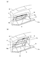
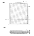
- FIG. 1 It is a perspective view which shows the light-emitting device for accessory cases of Example 1 of this invention. It is the front view and sectional drawing of the organic electroluminescent light emission panel in the light-emitting device of FIG. It is a block diagram which shows the drive control system which drives the organic electroluminescent light emission panel in the light-emitting device of FIG. It is a perspective view which each shows the illumination state in the accessory case by the light-emitting device of FIG. 1, and the illumination state in a vehicle interior. It is a perspective view which shows the light-emitting device for accessory cases of Example 2 of this invention. It is a front view of the organic electroluminescent light emission panel in the light-emitting device of FIG. FIG.
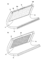
- FIG. 6 is a block diagram showing a drive control system for driving an organic EL light emitting panel in the light emitting device of FIG. 5. It is a perspective view which each shows the illumination state in the accessory case by the light-emitting device of FIG. 5, and the illumination state in a vehicle interior. It is a perspective view which shows the light-emitting device for accessory cases of Example 3 of this invention. It is the front view and sectional drawing of the organic electroluminescent light emission panel in the light-emitting device of FIG. It is a perspective view which each shows the illumination state in the accessory case by the light-emitting device of FIG. 9, and the illumination state in a vehicle interior. It is a perspective view which shows the light-emitting device for accessory cases of Example 4 of this invention.
- the holder 11 has a light emitting opening 13 on the front surface thereof so that the light emitting surface 12a of the organic EL light emitting panel 12 is exposed to the outside when the organic EL light emitting panel 12 is housed inside.
- the light exit opening 13 has substantially the same shape as the rectangular shape of the actual light emitting region of the light emitting surface 12a of the organic EL light emitting panel 12.
- the rear surface of the holder 11 is an attachment surface (not shown) attached to the interior of the accessory case of the vehicle.
- the holder 11 holds the organic EL light emitting panel 12 movably in the direction along the plane, and also pulls out the organic EL light emitting panel 12 from the holder 11 along the light emitting surface 12a in the moving direction.
- a drawer opening 15 communicating with the internal space is provided.
- the drawer opening 15 corresponds to the upper side surface among the four side surfaces between the front surface and the rear surface of the holder 11 and communicates with the light emitting opening portion 13.
- the remaining outer peripheral portion of the front surface of the holder 11 other than the light emitting opening 13 serves as a holding portion 14.
- the holding portion 14 has a U-shaped cross section including the back surface and the side surface portion of the outer peripheral portion of the holder 11.
- the organic EL light emitting panel 12 is slidably held when the edge of the organic EL light emitting panel 12 enters the inside of the U-shaped holding portion 14.
- the organic EL light emitting panel 12 In the state where the organic EL light emitting panel 12 is housed in the holder 11, as shown in FIG. 1, the upper portion of the organic EL light emitting panel 12 protrudes slightly from the drawer opening 15 to the outside. Further, the organic EL light emitting panel 12 has a handle 16 (operation unit) at the upper portion as shown in FIGS. 1 and 2A. The handle 16 is used when the organic EL light emitting panel 12 is pulled out. A stopper mechanism for preventing further movement of the organic EL light emitting panel 12 when the organic EL light emitting panel 12 is pulled out from the holder 11 and most of the light emitting surface 12a is located above the light emitting opening 13 is provided with the holder 11 and It may be provided in at least one of the organic EL light emitting panels 12.
- the holder 11 may have a mechanism for holding the organic EL light-emitting panel 12 in a state where movement of the organic EL light-emitting panel 12 is stopped at an arbitrary movement position.
- the inside of the organic EL light emitting panel 12 is shown in FIG. 2 (b) as a cross-section of the XY portion of FIG. 2 (a), and an organic function including a transparent electrode anode 22 and a light emitting layer on a transparent substrate 21.
- the layer 23, the metal electrode cathode 24, and the sheet-like transparent member 25 are sequentially laminated.
- the anode 22, the organic functional layer 23, and the cathode 24 are organic EL elements, and a plurality of these organic EL elements may be formed on the transparent substrate 21.
- the above-described laminated portion of the organic EL light emitting panel 12 is covered with a protective material 27 made of a resin having optical transparency. Although not shown between the laminated portion and the protective material 27, an adhesive may be filled.
- FIG. 3 shows the configuration of the drive control system 40 of the light emitting device 10 of FIG.
- the drive control system 40 drives the organic EL light-emitting panel 12 using a vehicle battery 41 as a power source.
- the brass terminal of the battery 41 is connected to a DC-DC converter 43 via an on / off switch 42.
- the negative terminal of the battery 41 is grounded.
- the on / off switch 42 is a switch that interlocks with opening / closing of an opening / closing lid 31a of the accessory case 31 described later. That is, the on / off switch 42 is turned off when the opening / closing lid 31a is closed, and the on / off switch 42 is turned on when the opening / closing lid 31a is opened.
- the DC-DC converter 43 converts the output DC voltage of the battery 41 into a drive voltage for the organic EL light emitting panel 12.
- a drive circuit 44 is connected to the output of the DC-DC converter 43.
- the drive circuit 44 includes, for example, a power transistor, and supplies a desired drive current between the anode 22 and the cathode 24 of the organic EL light emitting panel 12 using the output voltage of the DC-DC converter 43.
- the drive control system 40 and each of the anode 22 and the cathode 24 of the organic EL light emitting panel 12 are connected via a cord (connection means) not shown. Note that the cord has a sufficient length so that the organic EL light-emitting panel 12 can slide in the holder 11.
- connection between the drive control system 40 and each of the anode 22 and the cathode 24 of the organic EL light emitting panel 12 does not use the above-described cord, and the holder 11 does not move even if the organic EL light emitting panel 12 slides inside the holder 11.
- a contact mechanism (not shown) that maintains electrical contact for each of the anode 22 and the cathode 24 may be provided between the organic EL light emitting panel 12 and the organic EL light emitting panel 12.
- the accessory case 31 is a storage box located in front of the passenger seat on the front panel 32 of the vehicle.
- the accessory case 31 is integrated with an opening / closing lid 31a, and the opening / closing lid 31a is a door that opens and closes an opening for taking in and out stored items (accessories) in the accessory case 31. By pulling the opening / closing lid 31a toward the passenger seat, the opening / closing lid 31a is opened.
- the accessory case 31 is configured as a storage box having a V-shaped bowl-shaped storage space.
- the light emitting device 10 is attached to an inner wall surface (innermost wall surface at the innermost position) facing obliquely with respect to the inner wall surface on the opening / closing lid 31a side inside the accessory case 31.
- the attachment method may be fixed by an adhesive or a screw, or may be detachably attached by a mechanical attachment mechanism.
- the on / off switch 42 is turned on, and the drive current is supplied to the organic EL light emitting panel 12, so that the organic EL light emitting panel 12 emits light.
- the light is emitted in the direction of arrow A from the light emitting surface 12 a of the organic EL light emitting panel 12. Since the organic EL light emitting panel 12 is accommodated in the internal illumination position in the holder 11, the accommodation space in the accessory case 31 is illuminated by the emitted light.
- a user such as a vehicle occupant can operate the handle 16 to move the organic EL light-emitting panel 12 from the holder 11 in the direction of arrow B.
- the organic EL light emitting panel 12 moves to the position where the organic EL light emitting panel 12 protrudes outside through the opening of the accessory case 31, that is, the external lighting position, the external EL light emitting panel 12 reaches the external lighting position and is from the light emitting surface 12a of the organic EL light emitting panel 12.
- the emitted light is directed into the vehicle interior in the direction of arrow C, and the vehicle interior can be illuminated.
- FIG. 5 shows an accessory case light emitting device 50 according to a second embodiment of the present invention.
- the accessory case light emitting device 50 of Example 2 includes an organic EL light emitting panel 17 including a first light emitting region 51 a and a second light emitting region 52 a in the vertical direction of the light emitting surface 17 a.
- the organic EL light emitting panel 17 includes a first light emitting unit 51 corresponding to the upper first light emitting region 51a and a second light emitting unit 52 corresponding to the lower second light emitting region 52a.
- each of the first light-emitting portion 51 and the second light-emitting portion 52 has the same structure as that of the organic EL light-emitting panel 12 of Example 1 shown in FIG. 2B, description thereof is omitted here.
- the structure including the shape of the holder 11 of the light-emitting device 50 of FIG. 5 and the organic EL light-emitting panel 17 is the same as that of the light-emitting device 10 of FIG. 1, and the same reference numerals are used for the same portions.
- the drive control system 60 of the light emitting device 50 individually drives the two light emitting units 51 and 52 of the organic EL light emitting panel 17 using a vehicle battery 61 as a power source.
- the brass terminal of the battery 61 is connected to a DC-DC converter 63 via an on / off switch 62.
- the negative terminal of the battery 61 is grounded.
- the on / off switch 62 is a switch (open / close detection means) that is linked to the opening / closing of the opening / closing lid 31a. That is, the on / off switch 62 is turned off when the opening / closing lid 31a is closed, and the on / off switch 62 is turned on when the opening / closing lid 31a is opened.
- the DC-DC converter 63 converts the output DC voltage of the battery 61 into a drive voltage for the organic EL light emitting panel 17.
- Two drive circuits 64 a and 64 b are connected to the output of the DC-DC converter 63.
- Each of the drive circuits 64 a and 64 b includes, for example, a power transistor, and supplies a desired drive current between the anode and the cathode of each of the light emitting units 51 and 52 using the output voltage of the DC-DC converter 63.
- the drive control system 60 and each of the anodes and cathodes of the light emitting units 51 and 52 are connected via a cord.
- the cord has a sufficient length so that the organic EL light-emitting panel 17 can slide on the holder 11.
- the drive control system 60 has a drawer detection unit 65 and a control unit 66.
- the drawer detection unit 65 is a drawer detection unit that detects that the organic EL light-emitting panel 17 has been pulled out and moved to a predetermined drawer position (external illumination position) in the holder 11.
- a detection method by the drawer detection unit 65 a mechanical detection method, a magnetic detection method, or an optical detection method can be used.
- the drawer detection unit 65 of the mechanical detection method is turned on when pressed by the organic EL light-emitting panel 17 when the organic EL light-emitting panel 17 is present at the drawer position (external illumination position) of the holder 11, and is present at other positions. It consists of an on / off switch that is turned off.
- the organic EL light emitting panel 17 is brought out in a non-contact position using the photo interrupter 111 and the light detection hole 112 formed in the organic EL light emitting panel 17 as shown in FIG. It may be detected that it has been pulled out.
- the photo interrupter 111 is provided in the holder 11, and when light detection holes 112 are positioned in the groove 111 a of the photo interrupter 111, light emitted from a light emitting unit (not shown) of the photo interrupter 111 is passed through the light detection holes 112. Since the light receiving unit (not shown) of the photo interrupter 111 receives the light, it is detected that the organic EL light emitting panel 17 has reached the drawing position.
- the drawer position detected by the drawer detector 65 may include a range from the position where the organic EL light-emitting panel 17 is most pulled out in the holder 11 to a position in the storage direction.
- a control unit 66 is connected to the output of the drawer detection unit 65.
- the control unit 66 can be configured by a logic circuit, for example.
- the control unit 66 instructs the drive circuits 64a and 64b to drive in accordance with a signal indicating the detection result of the drawer detection unit 65. Specifically, when the drawer detection unit 65 detects that the organic EL light emitting panel 17 does not exist at the drawing position, a drive command is generated for the drive circuit 64a, and the drawer detection unit 65 generates the organic EL light emitting panel 17. Is detected at the pull-out position, a drive command is generated for both the drive circuits 64a and 64b.
- the accessory case light emitting device 50 is attached to the accessory case 31 of the vehicle as shown in FIG.
- the accessory case 31 is a storage box located in front of the front passenger seat of the front panel 32 of the vehicle.
- the light emitting device 50 is attached to a surface facing the opening / closing lid 31a side inside the accessory case 31 at an angle, and the attachment method is the same as in the first embodiment.
- the on / off switch 62 is turned on. Further, when the organic EL light emitting panel 17 is held at the internal illumination position of the holder 11 as shown in FIG. 8A, the organic EL light emitting panel 17 does not exist at the drawer position by the drawer detection unit 65. Thus, the control unit 66 generates a drive command for the drive circuit 64a. Since the drive circuit 64a supplies a drive current to the first light emitting unit 51 of the organic EL light emitting panel 17 in accordance with the drive command, the first light emitting unit 51 emits light, and the light is emitted from the first light emitting region of the organic EL light emitting panel 17.
- the light is emitted from 51a in the direction indicated by the arrow A. Therefore, the storage space inside the accessory case 31 is illuminated by the light emitted from the first light emitting region 51a.
- the controller 66 does not generate a drive command for the drive circuit 64b
- the drive circuit 64b does not drive the second light emitting unit 52 of the organic EL light emitting panel 17. Therefore, since the second light emitting unit 52 does not emit light, no light is emitted from the second light emitting region 52a. Since the light emitted from the first light emitting region 51a is sufficient for illumination inside the accessory case 31, which is a narrow storage space, energy saving can be achieved.
- a user such as a vehicle occupant can operate the handle 16 to move the organic EL light emitting panel 17 from the holder 11 in the direction of arrow B.
- the extraction detection unit 65 detects that the organic EL light emission panel 17 exists at the extraction position, and thereby the control unit 66 generates a drive command for the drive circuits 64a and 64b. Since the drive circuit 64a continuously supplies the drive current to the first light emitting unit 51 of the organic EL light emitting panel 17 according to the drive command, the light emission of the first light emitting unit 51 is maintained, and the light is emitted from the organic EL light emitting panel 17.
- the drive circuit 64b supplies a drive current to the second light emitting unit 52 of the organic EL light emitting panel 17 in accordance with the drive command, the second light emitting unit 52 emits light, and the light is emitted from the second light emitting region of the organic EL light emitting panel 17. Similarly, the light is emitted in the direction indicated by arrow C from 52a. Therefore, the emitted light from each of the first and second light emitting areas 51a and 52a of the organic EL light emitting panel 17 is directed into the vehicle interior, and the vehicle interior can be illuminated. Since the interior of the vehicle is illuminated by the light emitted from each of the first and second light emitting areas 51a and 52a, the interior can be illuminated brightly even in a large interior.
- FIG. 9 shows an accessory case light emitting device 70 of Example 3 of the present invention.
- the accessory case light emitting device 70 includes a holder 18 and an organic EL light emitting panel 19.
- the organic EL light emitting panel 19 is a quadrangular flexible panel (a panel having flexibility), and as shown in FIG. 10, one main surface thereof is a light emitting surface 19a that emits light to the outside, and the other main surface.
- a surface (not shown) is a sealing surface.
- the holder 18 is made of a synthetic resin and is formed in a curved shape in accordance with the shape of the bowl inside the accessory case 31 described above.
- a curved center line (not shown) is located at a position that bisects the holder 18 by a straight line in the lateral direction of the holder 18.
- the curved inner side of the holder 18 is the front side of the holder 18.
- the holder 18 is held in the internal space so that the light emitting surface 19 a of the organic EL light emitting panel 19 is
- the holder 18 has a light emitting opening 71 on the front surface thereof so that the light emitting surface 19a of the organic EL light emitting panel 19 is exposed to the outside when the organic EL light emitting panel 19 is held inside.
- the light emission opening 71 has substantially the same size as that of the upper light emitting surface 19a of the organic EL light emitting panel 19, for example, the upper half light emitting region.
- the rear surface of the holder 18 is an attachment surface (not shown) attached to the interior of the accessory case of the vehicle.
- the holder 18 holds the organic EL light-emitting panel 19 so as to be slidable in the vertical direction, and has a drawer opening 72 for pulling out the organic EL light-emitting panel 19 from the holder 18 in the sliding direction.
- the drawer opening 72 corresponds to the upper surface of the four side surfaces between the front surface and the rear surface of the holder 18 and communicates with the light emitting opening 71.
- the remaining part of the front surface of the holder 18 other than the light emitting opening 13 serves as a holding part 73 of the organic EL light emitting panel 19.
- the organic EL light-emitting panel 19 has a handle 74 at the upper portion as shown in FIGS. 9 and 10A.
- the handle 74 is used when pulling out the organic EL light emitting panel 19.
- a stopper mechanism for preventing further movement of the organic EL light emitting panel 19 when the organic EL light emitting panel 19 is pulled out from the holder 18 and most of the light emitting surface 19a is positioned above the light emitting opening 13 is provided with the holder 18 and It may be provided in at least one of the organic EL light emitting panels 19.
- the inside of the organic EL light emitting panel 19 is shown in FIG. 10 (b) as a cross-section of the XY portion of FIG. 10 (a).
- a transparent electrode anode 82 and a light emitting layer are provided on a flexible transparent substrate 81.
- the organic functional layer 83 includes a cathode 84 of a flexible metal electrode, and a sheet-like flexible transparent member 85 is sequentially laminated.
- the anode 82, the organic functional layer 83, and the cathode 84 are organic EL elements, and a plurality of these organic EL elements may be formed on the transparent substrate 81.
- the above-described laminated portion of the organic EL light-emitting panel 82 is covered with a flexible protective material 87 made of a resin having optical transparency. Although not shown between the laminated portion and the protective material 87, an adhesive may be filled.
- 10B shows the organic EL light-emitting panel 19 as a flat panel. However, the organic EL light-emitting panel 19 is curved when a force is applied from the outside, and when the force is removed, the curved shape is maintained as it is. It may be a panel having the property of returning to itself or a panel having the property of returning itself to a flat state.
- the drive control system 40 shown in FIG. 3 is used as it is.
- the drive circuit 44 supplies a desired drive current between the anode 82 and the cathode 84 of the organic EL light emitting panel 19 using the output voltage of the DC-DC converter 43.
- the light emitting device 10 is attached to the inner wall surface of the accessory case 31 on the side of the opening / closing lid 31a and the inner wall surface obliquely facing the inner wall surface.
- the attachment method may be fixed by an adhesive or a screw, or may be detachably attached by a mechanical attachment mechanism.
- the on / off switch 42 is turned on, and the drive current is supplied to the organic EL light emitting panel 19, so that the organic EL light emitting panel 19 emits light.
- the light is emitted in the direction indicated by the arrow A from the light emitting surface 19 a of the organic EL light emitting panel 19. Since the organic EL light emitting panel 19 is housed in the holder 18, a part of the light emitted from the light emitting surface 19 a illuminates the housing space inside the accessory case 31 through the light emitting opening 71. As shown in FIG.
- a user such as a vehicle occupant can operate the handle 74 to move the organic EL light-emitting panel 19 out of the holder 18 in the direction indicated by the arrow B.
- the organic EL light emitting panel 19 moves in this way, light is emitted in the direction indicated by the arrow C from the entire light emitting surface 19a of the organic EL light emitting panel 19. The emitted light is directed into the vehicle interior, and illumination of the vehicle interior can be performed.
- FIG. 12 shows an accessory case light emitting device 90 according to a fourth embodiment of the present invention.
- the accessory case light emitting device 90 includes a flexible organic EL light emitting panel 91 including a first light emitting region 92a and a second light emitting region 93a in the vertical direction of the light emitting surface 91a. ing. That is, the organic EL light emitting panel 91 includes a first light emitting unit (not shown) corresponding to the upper first light emitting region 92a and a second light emitting unit (not shown) corresponding to the lower second light emitting region 93a. .
- each of the first light-emitting part and the second light-emitting part has the same structure as that of the organic EL light-emitting panel 19 of Example 3 shown in FIG. 10B, description thereof is omitted here. Further, the configuration including the shape of the holder 18 of the light emitting device 90 and the organic EL light emitting panel 91 of FIG. 12 is the same as that of the light emitting device 70 of FIG. 9, and the same reference numerals are used for the same portions.
- the drive control system of the light emitting device 90 As the drive control system of the light emitting device 90, the drive control system 60 shown in FIG. 7 is used as it is.
- Each of the drive circuits 64a and 64b supplies a desired drive current between the anode and the cathode of each light emitting unit using the output voltage of the DC-DC converter 63.
- the light emitting device 90 is attached to the accessory case 31 of the vehicle as shown in FIG.
- the accessory case 31 is a storage box located in front of the front passenger seat of the front panel 32 of the vehicle.
- the light emitting device 90 is attached to the inner wall surface of the accessory case 31 on the opening / closing lid 31a side and the inner wall surface obliquely facing the inner wall surface, and the attachment method is the same as in the third embodiment.
- the on / off switch 62 is turned on. 14A, when the organic EL light emitting panel 91 is held at the internal illumination position by the holder 18, the organic EL light emitting panel 91 is not present at the drawer position by the drawer detection unit 65. Accordingly, the control unit 66 generates a drive command for the drive circuit 64a. Since the drive circuit 64a supplies a drive current to the first light emitting unit of the organic EL light emitting panel 91 in response to the drive command, the first light emitting unit emits light, and the light is emitted from the first light emitting region 92a of the organic EL light emitting panel 19. The light is emitted in the direction indicated by arrow A.
- the storage space inside the accessory case 31 is illuminated by the light emitted from the first light emitting region 92a.
- the control unit 66 does not generate a drive command for the drive circuit 64b
- the drive circuit 64b does not drive the second light emitting unit of the organic EL light emitting panel 91. Therefore, since the second light emitting unit does not emit light, no light is emitted from the second light emitting region 93a. Since the light emitted from the first light emitting region 92a is sufficient for illumination inside the accessory case 31, which is a narrow storage space, energy saving can be achieved.
- a user such as a vehicle occupant can operate the handle 74 to pull out the organic EL light emitting panel 91 from the holder 18 and move it in the direction indicated by the arrow B.
- the extraction detecting unit 65 detects that the organic EL light emitting panel 91 exists at the extraction position, and thereby the control unit 66 generates a drive command for the drive circuits 64a and 64b.
- the drive circuit 64a continuously supplies a drive current to the first light emitting unit of the organic EL light emitting panel 91 in response to the drive command, the light emission of the first light emitting unit is maintained, and the light is emitted from the organic EL light emitting panel 91.
- the light is emitted from one light emitting region 92a in a direction indicated by an arrow C.
- the drive circuit 64b supplies a drive current to the second light emitting unit of the organic EL light emitting panel 91 in response to the drive command, the second light emitting unit emits light, and the light is emitted from the second light emitting region 93a of the organic EL light emitting panel 91. Similarly, the light is emitted in the direction indicated by the arrow C.
- the emitted light from each of the first and second light emitting regions 92a and 93a of the organic EL light emitting panel 91 is directed into the vehicle interior, and the vehicle interior can be illuminated. Since the interior of the vehicle is illuminated by the light emitted from each of the first and second light emitting regions 92a and 93a, the interior can be illuminated brightly even in a large interior.
- FIGS. 15 (a) and 15 (b) show a light-emitting device 100 for putting accessories of Example 5 of the present invention.
- a light reflecting plate 101 is added to the light emitting device 70 shown as the third embodiment.
- the light reflecting plate 101 is disposed on the inner wall surface of the holder 18 facing the light emission opening 71.
- the organic EL light emitting panel 99 is not held, the light emission opening 71 is formed. Exposed to the outside.
- the light reflecting plate 101 has the same size as the light emitting opening 71.
- the light reflecting plate 101 may be formed by attaching a metal plate such as an aluminum plate or a silver plate to the inner wall surface of the holder 18 or may be formed by performing a metal plating process on the inner wall surface of the holder 18.
- the organic EL light emitting panel 99 has a light emitting surface 99b (FIG. 17B) on the opposite surface in addition to the light emitting surface 99a.
- the inside of the organic EL light emitting panel 99 is shown in FIG. 16 (b) as a cross-section of the XY portion of FIG. 16 (a).
- the transparent electrode anode 82 and the light emitting layer are provided on the flexible transparent substrate 81.
- the organic functional layer 83 includes a cathode 84a of a flexible transparent electrode, and a sheet-like flexible transparent member 85 are sequentially stacked.
- the anode 82, the organic functional layer 83, and the cathode 84 a are organic EL elements, and a plurality of these organic EL elements may be formed on the transparent substrate 81.
- the organic EL light emitting panel 99 of Example 5 emits light on both sides because the cathode 84a is formed of a flexible transparent material.
- the on / off switch 42 is turned on and a driving current is supplied to the organic EL light emitting panel 99.
- the light emitting panel 99 emits light.
- Light emitted from the anode 82 side of the organic functional layer 83 is emitted in the direction indicated by the arrow A from one light emitting surface 99a.
- a part of the light emitted from the cathode 84 a side of the organic functional layer 83 is reflected by the light reflecting plate 101, passes through the organic EL light emitting panel 99, and is emitted from one light emitting surface 99 a. Since the organic EL light emitting panel 99 is housed in the holder 18, a part of the emitted light on the light emitting surface 99 a illuminates the interior of the accessory case 31 through the light emitting opening 71.
- a user such as a vehicle occupant can operate the handle 74 to move the organic EL light-emitting panel 99 out of the holder 18.
- the organic EL light emitting panel 99 moves in this way, light is emitted from both light emitting surfaces 99a and 99b of the organic EL light emitting panel 19, so that the emitted light is not only in the accessory case 31 indicated by the arrow C, but also in the arrow D.
- the vehicle interior can be illuminated in a wide range.
- the light emitting device for compartment accessory is shown, but the present invention is not limited to this and can be applied to a storage box such as a furniture drawer. Further, the present invention is not limited to a storage box for a vehicle such as an automobile or a two-wheeled vehicle, but can be applied to a storage box for a vehicle such as a ship or an airplane.
- the organic EL light-emitting panel is shown as the surface light-emitting panel, but the configuration of the organic EL light-emitting panel is not limited to that shown in the embodiment.
- the present invention may use a light emitting panel other than the organic EL light emitting panel, for example, a light emitting panel in which a plurality of light emitting elements are arranged to enable surface light emission.
Landscapes
- Engineering & Computer Science (AREA)
- Mechanical Engineering (AREA)
- Arrangements Of Lighting Devices For Vehicle Interiors, Mounting And Supporting Thereof, Circuits Therefore (AREA)
Description
本発明は、収納ボックス内を照明する収納ボックス用発光装置に関する。
車両には通常、小物等の収納物を収容するための収納ボックスが設けられている。車両用の収納ボックスとしては例えば、車両のフロントパネルの助手席前方に位置する小物入れが一般的である。そのような車両用小物入れの内部を照明する技術は特許文献1等の先行技術文献で提案されている。
特許文献1に示された車両用小物入れにおいては、小物入れを開閉する開閉蓋に有機EL(エレクトロルミネッセンス)照明装置が設けられ、開閉蓋が開かれたときに有機EL照明装置を発光させて小物入れ内を照明することが行われる。また、有機EL照明装置は両面発光するので、開閉蓋が閉じられたときに車室内を照明する車室灯としても利用される。
しかしながら、特許文献1に示されたような従来技術の小物入れ照明装置では、小物入れの内部の照明には適しているが、小物入れの位置が助手席前方等の車室内の下部にあることが多いため車室内全体を十分に照明することができないという課題があった。
そこで、本発明が解決しようとする課題は、上記の欠点が一例として挙げられ、小物入れ等の収納ボックスの内部の照明だけでなく収納ボックス周囲を十分に照明することができる収納ボックス用発光装置を提供することが本発明の目的である。
請求項1に係る発明の収納ボックス用発光装置は、収納物の出し入れ用の開口部を備えた収納空間を有する収納ボックス内を照明する発光装置であって、面発光パネルと、前記収納ボックス内の内壁に取り付けられ、前記面発光パネルの発光面を前記収納ボックス内の前記収納空間に露出させた状態の内部照明位置にて前記面発光パネルを保持するホルダと、を備え、前記ホルダは、前記面発光パネルが前記開口部より外部に突出して前記収納ボックス外を照明するように前記面発光パネルを移動自在に保持することを特徴としている。
以下、本発明の実施例を、図面を参照しつつ詳細に説明する。
図1に示した本発明の実施例1の小物入れ用発光装置10は、ホルダ11及び有機EL発光パネル12を有している。有機EL発光パネル12は面発光パネルであって、4角形で平面状である。有機EL発光パネル12の一方の主面が外部に光を放出する発光面12aであり、他方の主面(図示せず)が封止面である。ホルダ11はそのような形状の有機EL発光パネル12を内部に収納するために、有機EL発光パネル12の横幅及び厚さより若干大きい内部空間を有している。ホルダ11は合成樹脂からなる。有機EL発光パネル12はその発光面12aがホルダ11の前面側に位置するようにホルダ11の内部に収納されている。
ホルダ11は、有機EL発光パネル12を内部に収納した時に有機EL発光パネル12の発光面12aが外部に露出するようにその前面に光出射開口部13を有する。光出射開口部13は有機EL発光パネル12の発光面12aの実際の発光領域の4角形状に合わせてそれとほぼ同一形状を有する。一方、ホルダ11の後面は車両の小物入れ内部に取り付ける取付面(図示せず)である。
また、ホルダ11は、有機EL発光パネル12をその平面に沿った方向に移動自在に保持すると共に有機EL発光パネル12を発光面12aに沿ってホルダ11内から移動方向に引き出すためにホルダ11の内部空間に連通した引き出し開口部15を有する。引き出し開口部15はホルダ11の前面と後面との間の4側面のうちの上側面に対応し、光出射開口部13に連通している。図1から分かるように、ホルダ11の前面のうちの光出射開口部13以外の残りの外周部分は保持部14となる。保持部14はホルダ11の外周部の裏面及び側面部分を含めて断面がコの字状となっている。そのコの字状の保持部14の内部に有機EL発光パネル12の縁部が入り込むことにより、有機EL発光パネル12がスライド可能に保持されている。
ホルダ11に有機EL発光パネル12が収納された状態では、図1に示すように、有機EL発光パネル12の上部が引き出し開口部15から若干外部に突出している。また、有機EL発光パネル12は、図1及び図2(a)に示すように取っ手16(操作部)を上部に有している。取っ手16は有機EL発光パネル12を引き出すときに使用するものである。有機EL発光パネル12がホルダ11から引き出されてその発光面12aの大部分が光出射開口部13より上方に位置するとき有機EL発光パネル12のそれ以上の移動を阻止するストッパ機構がホルダ11及び有機EL発光パネル12の少なくとも一方に備えられても良い。
更に、ホルダ11は有機EL発光パネル12を任意の移動位置において有機EL発光パネル12の移動を停止した状態で保持する機構を有しても良い。
有機EL発光パネル12の内部は、図2(a)のX-Y部分の断面として図2(b)に示されており、透明基板21上に透明電極の陽極22、発光層を含む有機機能層23、金属電極の陰極24、シート状の透明部材25が順に積層された構造を有する。陽極22、有機機能層23及び陰極24が有機EL素子であり、透明基板21上にはこの有機EL素子が複数形成されても良い。
有機EL発光パネル12の上記した積層部分は、光透過性を有する樹脂からなる保護材27によって覆われている。なお、積層部分と保護材27との間には図示していないが、接着剤が充填されても良い。
図3は図1の発光装置10の駆動制御系40の構成を示している。この駆動制御系40は車両のバッテリ41を電源として有機EL発光パネル12を駆動する。バッテリ41のブラス端子はオンオフスイッチ42を介してDC-DCコンバータ43に接続されている。バッテリ41のマイナス端子はグランド接続されている。オンオフスイッチ42は後述の小物入れ31の開閉蓋31aの開閉に連動するスイッチである。すなわち、開閉蓋31aの閉状態ではオンオフスイッチ42はオフとなり、開閉蓋31aの開状態ではオンオフスイッチ42はオンとなる。DC-DCコンバータ43はバッテリ41の出力直流電圧を有機EL発光パネル12の駆動電圧に変換する。DC-DCコンバータ43の出力には駆動回路44が接続されている。駆動回路44は例えば、パワートランジスタを有し、DC-DCコンバータ43の出力電圧を用いて有機EL発光パネル12の陽極22と陰極24との間に所望の駆動電流を供給する。駆動制御系40と有機EL発光パネル12の陽極22及び陰極24各々との間は図示しないコード(接続手段)を介して接続されている。なお、そのコードは有機EL発光パネル12がホルダ11においてスライド移動できるように十分の長さを持っている。なお、駆動制御系40と有機EL発光パネル12の陽極22及び陰極24各々との間の接続は上記のコードを用いないで、ホルダ11内部に有機EL発光パネル12がスライド移動してもホルダ11と有機EL発光パネル12との間に陽極22と陰極24各々用の電気的接触を維持する接触機構(図示せず)を設けても良い。
図1の小物入れ用発光装置10は図4(a)に示すように、車両の小物入れ31に取り付けられる。小物入れ31は車両のフロントパネル32の助手席前方に位置する収納ボックスである。また、小物入れ31は開閉蓋31aと一体になっており、開閉蓋31aは小物入れ31で収納物(小物)を出し入れする開口部を開閉するドアである。開閉蓋31aを助手席側に引くことにより、開閉蓋31aが開状態となる。小物入れ31はV字の樋状の収納空間を有する収納ボックスとして構成されている。小物入れ31の内部の開閉蓋31a側の内壁面に対して斜めに対面した内壁面(最奥位置の内壁面)に発光装置10は取り付けられている。取付方法は例えば、接着剤やネジによって固定されても良いし、機械的な取付機構により着脱自在に取り付けられても良い。
図4(a)に示した開閉蓋31aの開状態では、上記のオンオフスイッチ42がオンとなり、有機EL発光パネル12に駆動電流が供給されるので、有機EL発光パネル12が発光する。その光は有機EL発光パネル12の発光面12aから矢印Aの方向に出射される。有機EL発光パネル12はホルダ11内の内部照明位置に収納されているので、出射光により小物入れ31の内部の収納空間が照明される。図4(b)に示すように、車両の搭乗者等の使用者は取っ手16を操作して有機EL発光パネル12をホルダ11内から矢印Bの方向に引き出して移動させることができる。このように有機EL発光パネル12が小物入れ31の開口部を通過して外部に突出した位置、すなわち外部照明位置まで移動すると、外部照明位置に達して有機EL発光パネル12の発光面12aからの出射光は矢印Cの方向で車室内に向けられ、車室内の照明を行うことができる。
図5は本発明の実施例2の小物入れ用発光装置50を示している。実施例2の小物入れ用発光装置50は図5及び図6に示すように、発光面17aの縦方向に第1発光領域51aと第2発光領域52aとを含む有機EL発光パネル17を有している。すなわち、有機EL発光パネル17は上部の第1発光領域51aに対応した第1発光部51と、下部の第2発光領域52aに対応した第2発光部52を有する。第1発光部51及び第2発光部52各々は図2(b)に示された実施例1の有機EL発光パネル12の構造と同一の構造を有するので、ここでの説明は省略される。また、図5の発光装置50のホルダ11及び有機EL発光パネル17の形状を含む構成は図1の発光装置10のものと同一であり、その同一部分は同一符号が用いられている。
実施例2の発光装置50の駆動制御系60は図7に示すように、車両のバッテリ61を電源として有機EL発光パネル17の2つの発光部51,52を個別に駆動する。バッテリ61のブラス端子はオンオフスイッチ62を介してDC-DCコンバータ63に接続されている。バッテリ61のマイナス端子はグランド接続されている。オンオフスイッチ62は上述の開閉蓋31aの開閉に連動するスイッチ(開閉検出手段)である。すなわち、開閉蓋31aの閉状態ではオンオフスイッチ62はオフとなり、開閉蓋31aの開状態ではオンオフスイッチ62はオンとなる。DC-DCコンバータ63はバッテリ61の出力直流電圧を有機EL発光パネル17の駆動電圧に変換する。DC-DCコンバータ63の出力には2つの駆動回路64a,64bが接続されている。駆動回路64a,64b各々は例えば、パワートランジスタを有し、DC-DCコンバータ63の出力電圧を用いて発光部51,52各々の陽極と陰極との間に所望の駆動電流を供給する。駆動制御系60と発光部51,52の陽極及び陰極各々との間はコードを介して接続されている。なお、そのコードは有機EL発光パネル17がホルダ11においてスライド移動できるように十分の長さを持っている。
また、駆動制御系60は引き出し検出部65と制御部66とを有している。引き出し検出部65は有機EL発光パネル17がホルダ11において予め定められた引き出し位置(外部照明位置)まで引き出し移動されたことを検出する引き出し検出手段である。引き出し検出部65による検出方法としては機械的検出方法、磁気的検出方法、又は光学的検出方法を用いることができる。例えば、機械的検出方法の引き出し検出部65は有機EL発光パネル17がホルダ11の引き出し位置(外部照明位置)に存在するとき有機EL発光パネル17によって押圧されてオンとなり、それ以外の位置に存在するときオフとなるオンオフスイッチからなる。光学的検出方法を採用する場合には、図18に示すようにフォトインタラプタ111と有機EL発光パネル17に形成した光検出用の孔112とを用いて非接触で有機EL発光パネル17が引き出し位置まで引き出されたことを検出しても良い。フォトインタラプタ111はホルダ11内に設けられ、フォトインタラプタ111の溝部111a内に光検出用の孔112が位置したときフォトインタラプタ111の図示しない発光部から発せられた光を光検出用の孔112を介してフォトインタラプタ111の図示しない受光部が受光するので、有機EL発光パネル17が引き出し位置に達したことが検出される。なお、引き出し検出部65によって検出される引き出し位置は有機EL発光パネル17がホルダ11において最も引き出された位置から若干収納方向の位置までの範囲を含んでも良い。
引き出し検出部65の出力には制御部66が接続されている。制御部66は例えば、ロジック回路によって構成することができる。制御部66は引き出し検出部65の検出結果を示す信号に応じて駆動回路64a,64b各々に対して駆動を指令する。具体的には、引き出し検出部65が有機EL発光パネル17が引き出し位置に存在しないことを検出した場合には駆動回路64aに対して駆動指令を生成し、引き出し検出部65が有機EL発光パネル17が引き出し位置に存在することを検出した場合には駆動回路64a,64b双方に対して駆動指令を生成する。
小物入れ用発光装置50は図8(a)に示すように、車両の小物入れ31に取り付けられる。小物入れ31は上記したように、車両のフロントパネル32の助手席前方に位置する収納ボックスである。小物入れ31の内部の開閉蓋31a側の面に対して斜めに対面した面に発光装置50は取り付けられており、取付方法は実施例1の場合と同様である。
図8(a)に示した開閉蓋31aの開状態では、上記のオンオフスイッチ62がオンとなる。また、図8(a)に示したように有機EL発光パネル17がホルダ11の内部照明位置に保持されている場合には、引き出し検出部65によって有機EL発光パネル17が引き出し位置に存在しないことが検出され、これにより制御部66は駆動回路64aに対して駆動指令を生成する。駆動回路64aは駆動指令に応じて有機EL発光パネル17の第1発光部51に駆動電流を供給するので、第1発光部51が発光し、その光は有機EL発光パネル17の第1発光領域51aから矢印Aで示す方向に出射される。よって、その第1発光領域51aからの出射光により小物入れ31の内部の収納空間が照明される。このとき、制御部66は駆動回路64bに対して駆動指令を生成しないので、駆動回路64bは有機EL発光パネル17の第2発光部52を駆動しない。よって、第2発光部52は発光しないので、第2発光領域52aからの光の出射はない。狭い収納空間である小物入れ31の内部の照明は第1発光領域51aからの出射光で十分であるので、省エネルギー化を図ることができる。
図8(b)に示すように、車両の搭乗者等の使用者は取っ手16を操作して有機EL発光パネル17をホルダ11内から矢印Bの方向に引き出して移動させることができる。このように有機EL発光パネル17が移動して上記した引き出し位置(外部照明位置)まで達すると、引き出し検出部65によって有機EL発光パネル17が引き出し位置に存在することが検出され、これにより制御部66は駆動回路64a,64bに対して駆動指令を生成する。駆動回路64aは駆動指令に応じて有機EL発光パネル17の第1発光部51に駆動電流を継続して供給するので、第1発光部51の発光が維持され、その光は有機EL発光パネル17の第1発光領域51aから矢印Cで示す方向に出射される。駆動回路64bは駆動指令に応じて有機EL発光パネル17の第2発光部52に駆動電流を供給するので、第2発光部52が発光し、その光は有機EL発光パネル17の第2発光領域52aから同様に矢印Cで示す方向に出射される。よって、有機EL発光パネル17の第1及び第2発光領域51a,52a各々からの出射光は車室内に向けられ、車室内の照明を行うことができる。車室内の照明は第1及び第2発光領域51a,52a各々からの出射光で行われるので、広い空間である車室内であっても明るく照明することができる。
図9は本発明の実施例3の小物入れ用発光装置70を示している。小物入れ用発光装置70は、ホルダ18及び有機EL発光パネル19を有している。有機EL発光パネル19は4角形のフレキシブルパネル(可撓性を有するパネル)であり、図10に示すように、その一方の主面が外部に光を放出する発光面19aであり、他方の主面(図示せず)が封止面である。ホルダ18は合成樹脂からなり、上記した小物入れ31の内部の樋形状に合わせて湾曲に形成されている。湾曲中心線(図示せず)はホルダ18の横方向の直線でホルダ18をほぼ2等分する位置にある。ホルダ18の湾曲した内側がホルダ18の前面側である。また、ホルダ18は有機EL発光パネル19の発光面19aがホルダ18の前面側に位置するように内部空間に保持されている。
ホルダ18は、有機EL発光パネル19を内部に保持した時に有機EL発光パネル19の発光面19aが外部に露出するようにその前面に光出射開口部71を有する。光出射開口部71は有機EL発光パネル19の発光面19aの上部、例えば、上部半分の発光領域に合わせてそれとほぼ同一大きさを有する。一方、ホルダ18の後面は車両の小物入れ内部に取り付ける取付面(図示せず)である。
また、ホルダ18は、有機EL発光パネル19をその縦方向においてスライド可能に保持すると共に有機EL発光パネル19をホルダ18内からスライド方向に引き出すために引き出し開口部72を有する。引き出し開口部72はホルダ18の前面と後面との間の4側面のうちの上側面に対応し、光出射開口部71に連通している。更に、図9から分かるように、ホルダ18の前面のうちの光出射開口部13以外の残りの部分は有機EL発光パネル19の保持部73となっている。また、有機EL発光パネル19は、図9及び図10(a)に示すように取っ手74を上部に有している。取っ手74は有機EL発光パネル19を引き出すときに使用するものである。有機EL発光パネル19がホルダ18から引き出されてその発光面19aの大部分が光出射開口部13より上方に位置するとき有機EL発光パネル19のそれ以上の移動を阻止するストッパ機構がホルダ18及び有機EL発光パネル19の少なくとも一方に備えられても良い。
有機EL発光パネル19の内部は、図10(a)のX-Y部分の断面として図10(b)に示されており、可撓性透明基板81上に透明電極の陽極82、発光層を含む有機機能層83、可撓性金属電極の陰極84、シート状の可撓性透明部材85が順に積層された構造を有する。陽極82、有機機能層83及び陰極84が有機EL素子であり、透明基板81上にはこの有機EL素子が複数形成されても良い。
有機EL発光パネル82の上記した積層部分は、光透過性を有する樹脂からなる可撓性保護材87によって覆われている。なお、積層部分と保護材87との間には図示していないが、接着剤が充填されても良い。また、図10(b)では有機EL発光パネル19を平面パネルとして示しているが、有機EL発光パネル19は外部から力を加えると湾曲し、その力を除去すると、その湾曲した形状をそのまま維持する性質を有するパネルであっても、或いは平面状態に自ら戻る性質を有するパネルであっても良い。
発光装置70の駆動制御系としては図3に示した駆動制御系40がそのまま用いられる。駆動回路44は、DC-DCコンバータ43の出力電圧を用いて有機EL発光パネル19の陽極82と陰極84との間に所望の駆動電流を供給する。
図9の小物入れ用発光装置70は図11(a)に示すように、車両の小物入れ31内に取り付けられる。小物入れ31の内部の開閉蓋31a側の内壁面及びその内壁面に対して斜めに対面した内壁面に発光装置10は取り付けられている。取付方法は例えば、接着剤やネジによって固定されても良いし、機械的な取付機構により着脱自在に取り付けられても良い。
図11(a)に示した開閉蓋31aの開状態では、上記のオンオフスイッチ42がオンとなり、有機EL発光パネル19に駆動電流が供給されるので、有機EL発光パネル19が発光する。その光は有機EL発光パネル19の発光面19aから矢印Aで示す方向に出射される。有機EL発光パネル19はホルダ18内に収納されているので、その発光面19aの一部の出射光は光出射開口部71を介して小物入れ31の内部の収納空間を照明する。図11(b)に示すように、車両の搭乗者等の使用者は取っ手74を操作して有機EL発光パネル19をホルダ18内から矢印Bで示す方向に引き出して移動させることができる。このように有機EL発光パネル19が移動すると、有機EL発光パネル19の発光面19a全体から矢印Cで示す方向に光が出射される。その出射光は車室内に向けられ、車室内の照明を行うことができる。
図12は本発明の実施例4の小物入れ用発光装置90を示している。小物入れ用発光装置90は、図12及び図13に示すように、発光面91aの縦方向に第1発光領域92aと第2発光領域93aとを含む可撓性有機EL発光パネル91を有している。すなわち、有機EL発光パネル91は上部の第1発光領域92aに対応した第1発光部(図示せず)と、下部の第2発光領域93aに対応した第2発光部(図示せず)を有する。第1発光部及び第2発光部各々は図10(b)に示された実施例3の有機EL発光パネル19の構造と同一の構造を有するので、ここでの説明は省略される。また、図12の発光装置90のホルダ18及び有機EL発光パネル91の形状を含む構成は図9の発光装置70のものと同一であり、その同一部分は同一符号が用いられている。
発光装置90の駆動制御系としては図7に示した駆動制御系60がそのまま用いられる。駆動回路64a,64b各々は、DC-DCコンバータ63の出力電圧を用いて発光部各々の陽極と陰極との間に所望の駆動電流を供給する。
発光装置90は図14(a)に示すように、車両の小物入れ31に取り付けられる。小物入れ31は上記したように、車両のフロントパネル32の助手席前方に位置する収納ボックスである。小物入れ31の内部の開閉蓋31a側の内壁面及びその内壁面に対して斜めに対面した内壁面に発光装置90は取り付けられており、取付方法は実施例3の場合と同様である。
図14(a)に示した開閉蓋31aの開状態では、上記のオンオフスイッチ62がオンとなる。また、図14(a)に示したように有機EL発光パネル91がホルダ18によって内部照明位置にて保持されている場合には、引き出し検出部65によって有機EL発光パネル91が引き出し位置に存在しないことが検出され、これにより制御部66は駆動回路64aに対して駆動指令を生成する。駆動回路64aは駆動指令に応じて有機EL発光パネル91の第1発光部に駆動電流を供給するので、第1発光部が発光し、その光は有機EL発光パネル19の第1発光領域92aから矢印Aで示す方向に出射される。よって、その第1発光領域92aからの出射光により小物入れ31の内部の収納空間が照明される。このとき、制御部66は駆動回路64bに対して駆動指令を生成しないので、駆動回路64bは有機EL発光パネル91の第2発光部を駆動しない。よって、第2発光部は発光しないので、第2発光領域93aからの光の出射はない。狭い収納空間である小物入れ31の内部の照明は第1発光領域92aからの出射光で十分であるので、省エネルギー化を図ることができる。
図14(b)に示すように、車両の搭乗者等の使用者は取っ手74を操作して有機EL発光パネル91をホルダ18内から引き出して矢印Bで示す方向に移動させることができる。このように有機EL発光パネル91が移動して上記した引き出し位置(外部照明位置)まで達すると、引き出し検出部65によって有機EL発光パネル91が引き出し位置に存在することが検出され、これにより制御部66は駆動回路64a,64bに対して駆動指令を生成する。駆動回路64aは駆動指令に応じて有機EL発光パネル91の第1発光部に駆動電流を継続して供給するので、第1発光部の発光が維持され、その光は有機EL発光パネル91の第1発光領域92aから矢印Cで示す方向に出射される。駆動回路64bは駆動指令に応じて有機EL発光パネル91の第2発光部に駆動電流を供給するので、第2発光部が発光し、その光は有機EL発光パネル91の第2発光領域93aから同様に矢印Cで示す方向に出射される。よって、有機EL発光パネル91の第1及び第2発光領域92a,93a各々からの出射光は車室内に向けられ、車室内の照明を行うことができる。車室内の照明は第1及び第2発光領域92a,93a各々からの出射光で行われるので、広い空間である車室内であっても明るく照明することができる。
図15(a),(b)は本発明の実施例5の小物入れ用発光装置100を示している。発光装置100では実施例3として示した発光装置70に光反射板101が追加されている。光反射板101は特に図15(b)に示すように、ホルダ18の光出射開口部71に対向した内壁面に配置され、有機EL発光パネル99が保持されていないときには光出射開口部71を介して外部に露出する。また、光反射板101は光出射開口部71と同等の大きさを有する。光反射板101としてはホルダ18の内壁面にアルミニウム板、銀板等の金属板を貼り付けても良いが、ホルダ18の内壁面に金属メッキ処理を施して形成しても良い。
有機EL発光パネル99は図16(a)に示すように発光面99aの他にその反対側の面にも発光面99b(図17(b))を有している。
有機EL発光パネル99の内部は、図16(a)のX-Y部分の断面として図16(b)に示されており、可撓性透明基板81上に透明電極の陽極82、発光層を含む有機機能層83、可撓性透明電極の陰極84a、シート状の可撓性透明部材85が順に積層された構造を有する。陽極82、有機機能層83及び陰極84aが有機EL素子であり、透明基板81上にはこの有機EL素子が複数形成されても良い。
この実施例5の有機EL発光パネル99は陰極84aが可撓性透明材料によって形成されているので両面発光する。
その他の発光装置100の構成は実施例3の発光装置70と同一であり、同一部分は同一符号を用いて図15(a),(b)及び図16(a),(b)では示されている。
小物入れ用発光装置100については、図17(a)に示した開閉蓋31aの開状態では、上記のオンオフスイッチ42がオンとなり、有機EL発光パネル99に駆動電流が供給されるので、有機EL発光パネル99が発光する。有機機能層83の陽極82側から発せられた光は一方の発光面99aから矢印Aで示す方向に出射される。また、有機機能層83の陰極84a側から発せられた光の一部は光反射板101で反射されて有機EL発光パネル99内を通過して一方の発光面99aから出射される。有機EL発光パネル99はホルダ18内に収納されているので、その発光面99aの一部の出射光は光出射開口部71を介して小物入れ31の内部を照明する。
図17(b)に示すように、車両の搭乗者等の使用者は取っ手74を操作して有機EL発光パネル99をホルダ18内から引き出して移動させることができる。このように有機EL発光パネル99が移動すると、有機EL発光パネル19の双方の発光面99a,99bから光が出射されるので、出射光は矢印Cで示す小物入れ31内だけでなく、矢印Dで示す車室内の方向に向けられ、車室内を広範囲に照明することができる。
なお、上記した各実施例では車室内小物入れ用発光装置を示したが、本発明はこれに限定されず、家具の引き出し等の収納ボックスに適用することができる。また、自動車、二輪自動車等の車両の収納ボックスに限らず、船、飛行機等の乗り物の収納ボックスに本発明は適用することができる。
また、上記した各実施例では、面発光パネルとして有機EL発光パネルを示したが、有機EL発光パネルの構成については実施例で示したものに限定されない。更に、本発明は面発光パネルとして、有機EL発光パネル以外の、例えば、複数の発光素子を配置して面発光を可能にした発光パネルを用いても良い。
10,50,70,90,100 発光装置
11,18 ホルダ
12,17,19,91,99 有機EL発光パネル
13,71 光出射開口部
15,72 引き出し開口部
31 小物入れ
40,60 駆動制御系
101 光反射板
11,18 ホルダ
12,17,19,91,99 有機EL発光パネル
13,71 光出射開口部
15,72 引き出し開口部
31 小物入れ
40,60 駆動制御系
101 光反射板
Claims (13)
- 収納物の出し入れ用の開口部を備えた収納空間を有する収納ボックス内を照明する発光装置であって、
面発光パネルと、
前記収納ボックス内の内壁に取り付けられ、前記面発光パネルの発光面を前記収納ボックス内の前記収納空間に露出させた状態の内部照明位置にて前記面発光パネルを保持するホルダと、を備え、
前記ホルダは、前記面発光パネルが前記開口部より外部に突出して前記収納ボックス外を照明するように前記面発光パネルを移動自在に保持することを特徴とする発光装置。 - 前記面発光パネルを発光駆動する駆動制御系を含むことを特徴とする請求項1記載の発光装置。
- 前記面発光パネルの発光面には複数の発光領域が配置され、
前記駆動制御系は、前記面発光パネルが前記内部照明位置から前記開口部を介して予め定められた外部照明位置まで引き出されたことを検出する引き出し検出手段を有し、
前記引き出し検出手段の検出結果に応じて、前記面発光パネルが前記内部照明位置に存在するとき前記複数の発光領域の一部の発光領域に対応した前記面発光パネルの発光部を発光駆動し、前記面発光パネルが前記外部照明位置に存在するとき前記複数の発光領域全てに対応した前記面発光パネルの発光部を発光駆動することを特徴とする請求項2記載の発光装置。 - 前記収納ボックスは、前記開口部を開閉する開閉蓋を有し、
前記駆動制御系は、前記開閉蓋の開閉を検出する開閉検出手段を有し、
前記開閉検出手段によって前記開閉蓋の開状態が検出されているとき前記面発光パネルを発光駆動することを特徴とする請求項2記載の発光装置。 - 前記ホルダは前記収納ボックスの内部形状に合わせて湾曲に形成され、
前記面発光パネルは可撓性を有することを特徴とする請求項1又は2記載の発光装置。 - 前記面発光パネルが前記内部照明位置に存在するとき前記面発光パネルの前記発光面の一部が前記ホルダの外部に露出され、前記面発光パネルが前記開口部から突出して移動するほど前記発光面が前記ホルダの外部への露出面積が増大することを特徴とする請求項1~5のいずれか1記載の発光装置。
- 前記一部の発光領域は前記複数の発光領域のうちの1つの発光領域であることを特徴とする請求項6記載の発光装置。
- 前記ホルダは前記発光面を前記収納空間に露出する光出射開口部を有することを特徴とする1~7のいずれか1記載の発光装置。
- 前記ホルダは前記光出射開口部に対向する内壁面に配置された光反射板を更に有し、
前記面発光パネルは光透過性の両面発光パネルであることを特徴とする請求項8記載の発光装置。 - 前記駆動制御系と前記面発光パネルとの間を電気的に接続する接続手段を有することを特徴とする請求項2~9のいずれか1記載の発光装置。
- 前記収納ボックスは乗り物の小物入れであり、
前記ホルダは前記小物入れの最奥位置の内壁に取り付けられることを特徴とする請求項1~10のいずれか1記載の発光装置。 - 前記面発光パネルは有機EL発光パネルであることを特徴とする請求項1~11のいずれか1記載の発光装置。
- 前記面発光パネルは前記ホルダに対する移動のための操作部を有することを特徴とする請求項1~12のいずれか1記載の発光装置。
Priority Applications (1)
| Application Number | Priority Date | Filing Date | Title |
|---|---|---|---|
| PCT/JP2012/066746 WO2014002264A1 (ja) | 2012-06-29 | 2012-06-29 | 収納ボックス用発光装置 |
Applications Claiming Priority (1)
| Application Number | Priority Date | Filing Date | Title |
|---|---|---|---|
| PCT/JP2012/066746 WO2014002264A1 (ja) | 2012-06-29 | 2012-06-29 | 収納ボックス用発光装置 |
Publications (1)
| Publication Number | Publication Date |
|---|---|
| WO2014002264A1 true WO2014002264A1 (ja) | 2014-01-03 |
Family
ID=49782487
Family Applications (1)
| Application Number | Title | Priority Date | Filing Date |
|---|---|---|---|
| PCT/JP2012/066746 Ceased WO2014002264A1 (ja) | 2012-06-29 | 2012-06-29 | 収納ボックス用発光装置 |
Country Status (1)
| Country | Link |
|---|---|
| WO (1) | WO2014002264A1 (ja) |
Cited By (2)
| Publication number | Priority date | Publication date | Assignee | Title |
|---|---|---|---|---|
| JP2018174160A (ja) * | 2018-08-03 | 2018-11-08 | 株式会社小糸製作所 | 灯具 |
| JP2019212641A (ja) * | 2019-09-18 | 2019-12-12 | パイオニア株式会社 | 発光装置 |
Citations (4)
| Publication number | Priority date | Publication date | Assignee | Title |
|---|---|---|---|---|
| JPS5562441U (ja) * | 1978-10-23 | 1980-04-28 | ||
| JPH0423538U (ja) * | 1990-06-20 | 1992-02-26 | ||
| JP2005177084A (ja) * | 2003-12-18 | 2005-07-07 | Toyota Industries Corp | 照明装置付き鏡及びサンバイザー |
| JP2007137234A (ja) * | 2005-11-17 | 2007-06-07 | Toyota Industries Corp | 車両用小物入れ |
-
2012
- 2012-06-29 WO PCT/JP2012/066746 patent/WO2014002264A1/ja not_active Ceased
Patent Citations (4)
| Publication number | Priority date | Publication date | Assignee | Title |
|---|---|---|---|---|
| JPS5562441U (ja) * | 1978-10-23 | 1980-04-28 | ||
| JPH0423538U (ja) * | 1990-06-20 | 1992-02-26 | ||
| JP2005177084A (ja) * | 2003-12-18 | 2005-07-07 | Toyota Industries Corp | 照明装置付き鏡及びサンバイザー |
| JP2007137234A (ja) * | 2005-11-17 | 2007-06-07 | Toyota Industries Corp | 車両用小物入れ |
Cited By (5)
| Publication number | Priority date | Publication date | Assignee | Title |
|---|---|---|---|---|
| JP2018174160A (ja) * | 2018-08-03 | 2018-11-08 | 株式会社小糸製作所 | 灯具 |
| JP2019212641A (ja) * | 2019-09-18 | 2019-12-12 | パイオニア株式会社 | 発光装置 |
| JP2021144941A (ja) * | 2019-09-18 | 2021-09-24 | パイオニア株式会社 | 発光装置 |
| JP2023053241A (ja) * | 2019-09-18 | 2023-04-12 | パイオニア株式会社 | 発光装置 |
| JP7450077B2 (ja) | 2019-09-18 | 2024-03-14 | パイオニア株式会社 | 発光装置 |
Similar Documents
| Publication | Publication Date | Title |
|---|---|---|
| US9738227B2 (en) | Storage assembly for vehicle center console | |
| US8870405B2 (en) | Drawer illumination device with magnetic reed switch | |
| JP4669552B2 (ja) | 照明構造 | |
| RU2015102987A (ru) | Устройство освещения | |
| TWI727406B (zh) | 照明組件及用於照亮存儲單元的方法 | |
| US10279664B1 (en) | Vehicle sunshade | |
| JP2017150274A (ja) | ドアハンドル | |
| WO2014002264A1 (ja) | 収納ボックス用発光装置 | |
| JP2017007503A (ja) | アシストグリップ | |
| US7481548B2 (en) | Portable case | |
| JP2012020679A (ja) | 自動車用荷室仕切装置、及び、自動車用荷室照明装置 | |
| JP6344706B2 (ja) | 昇降収納装置 | |
| EP3190329A1 (en) | Multi-use auxiliary light | |
| JP7215598B2 (ja) | 電気機器及び電気機器システム | |
| JP2001151012A (ja) | 照明装置 | |
| JP2015157572A (ja) | 照明装置及び乗り物 | |
| JP2002307326A (ja) | 電動工具 | |
| JP6907037B2 (ja) | 乗物用の室内照明装置 | |
| JP6635509B2 (ja) | 照明付き車両用ドアハンドルプロテクターとその照明構造 | |
| JP4629520B2 (ja) | 車両用照明装置 | |
| GB2577179A (en) | Illumination for storage units | |
| WO2014002214A1 (ja) | 透光性窓板取付型発光装置 | |
| JP2011135917A (ja) | ミラーキャビネット照明装置 | |
| JP2007320355A (ja) | 車両用収容具 | |
| JP2005280594A (ja) | サイドバイザー |
Legal Events
| Date | Code | Title | Description |
|---|---|---|---|
| 121 | Ep: the epo has been informed by wipo that ep was designated in this application |
Ref document number: 12880060 Country of ref document: EP Kind code of ref document: A1 |
|
| NENP | Non-entry into the national phase |
Ref country code: DE |
|
| 122 | Ep: pct application non-entry in european phase |
Ref document number: 12880060 Country of ref document: EP Kind code of ref document: A1 |
|
| NENP | Non-entry into the national phase |
Ref country code: JP |