WO2013191275A1 - Dispositif de commande - Google Patents
Dispositif de commande Download PDFInfo
- Publication number
- WO2013191275A1 WO2013191275A1 PCT/JP2013/067088 JP2013067088W WO2013191275A1 WO 2013191275 A1 WO2013191275 A1 WO 2013191275A1 JP 2013067088 W JP2013067088 W JP 2013067088W WO 2013191275 A1 WO2013191275 A1 WO 2013191275A1
- Authority
- WO
- WIPO (PCT)
- Prior art keywords
- name
- sql statement
- user program
- definition information
- program
- Prior art date
Links
Images


Classifications
-
- G—PHYSICS
- G06—COMPUTING; CALCULATING OR COUNTING
- G06F—ELECTRIC DIGITAL DATA PROCESSING
- G06F16/00—Information retrieval; Database structures therefor; File system structures therefor
- G06F16/20—Information retrieval; Database structures therefor; File system structures therefor of structured data, e.g. relational data
- G06F16/24—Querying
- G06F16/245—Query processing
- G06F16/2455—Query execution
- G06F16/24564—Applying rules; Deductive queries
-
- G—PHYSICS
- G05—CONTROLLING; REGULATING
- G05B—CONTROL OR REGULATING SYSTEMS IN GENERAL; FUNCTIONAL ELEMENTS OF SUCH SYSTEMS; MONITORING OR TESTING ARRANGEMENTS FOR SUCH SYSTEMS OR ELEMENTS
- G05B19/00—Programme-control systems
- G05B19/02—Programme-control systems electric
- G05B19/04—Programme control other than numerical control, i.e. in sequence controllers or logic controllers
- G05B19/05—Programmable logic controllers, e.g. simulating logic interconnections of signals according to ladder diagrams or function charts
- G05B19/056—Programming the PLC
-
- G—PHYSICS
- G06—COMPUTING; CALCULATING OR COUNTING
- G06F—ELECTRIC DIGITAL DATA PROCESSING
- G06F16/00—Information retrieval; Database structures therefor; File system structures therefor
- G06F16/20—Information retrieval; Database structures therefor; File system structures therefor of structured data, e.g. relational data
- G06F16/28—Databases characterised by their database models, e.g. relational or object models
- G06F16/284—Relational databases
-
- G—PHYSICS
- G05—CONTROLLING; REGULATING
- G05B—CONTROL OR REGULATING SYSTEMS IN GENERAL; FUNCTIONAL ELEMENTS OF SUCH SYSTEMS; MONITORING OR TESTING ARRANGEMENTS FOR SUCH SYSTEMS OR ELEMENTS
- G05B19/00—Programme-control systems
- G05B19/02—Programme-control systems electric
- G05B19/418—Total factory control, i.e. centrally controlling a plurality of machines, e.g. direct or distributed numerical control [DNC], flexible manufacturing systems [FMS], integrated manufacturing systems [IMS], computer integrated manufacturing [CIM]
- G05B19/4185—Total factory control, i.e. centrally controlling a plurality of machines, e.g. direct or distributed numerical control [DNC], flexible manufacturing systems [FMS], integrated manufacturing systems [IMS], computer integrated manufacturing [CIM] characterised by the network communication
- G05B19/4186—Total factory control, i.e. centrally controlling a plurality of machines, e.g. direct or distributed numerical control [DNC], flexible manufacturing systems [FMS], integrated manufacturing systems [IMS], computer integrated manufacturing [CIM] characterised by the network communication by protocol, e.g. MAP, TOP
-
- G—PHYSICS
- G05—CONTROLLING; REGULATING
- G05B—CONTROL OR REGULATING SYSTEMS IN GENERAL; FUNCTIONAL ELEMENTS OF SUCH SYSTEMS; MONITORING OR TESTING ARRANGEMENTS FOR SUCH SYSTEMS OR ELEMENTS
- G05B2219/00—Program-control systems
- G05B2219/30—Nc systems
- G05B2219/31—From computer integrated manufacturing till monitoring
- G05B2219/31369—Translation, conversion of protocol between two layers, networks
-
- Y—GENERAL TAGGING OF NEW TECHNOLOGICAL DEVELOPMENTS; GENERAL TAGGING OF CROSS-SECTIONAL TECHNOLOGIES SPANNING OVER SEVERAL SECTIONS OF THE IPC; TECHNICAL SUBJECTS COVERED BY FORMER USPC CROSS-REFERENCE ART COLLECTIONS [XRACs] AND DIGESTS
- Y02—TECHNOLOGIES OR APPLICATIONS FOR MITIGATION OR ADAPTATION AGAINST CLIMATE CHANGE
- Y02P—CLIMATE CHANGE MITIGATION TECHNOLOGIES IN THE PRODUCTION OR PROCESSING OF GOODS
- Y02P90/00—Enabling technologies with a potential contribution to greenhouse gas [GHG] emissions mitigation
- Y02P90/02—Total factory control, e.g. smart factories, flexible manufacturing systems [FMS] or integrated manufacturing systems [IMS]
Definitions
- the present invention relates to a control device such as a programmable logic controller (PLC), and more particularly to a technique for facilitating access to a database system.
- PLC programmable logic controller
- a control device such as a PLC is used for controlling an automatic machine such as a factory and has a plurality of input / output functions, for example, sequentially reading values output from a sensor or the like and holding data.
- Patent Document 1 discloses a data collection device that can transmit I / O data of a PLC to a host computer in real time.
- an object of the present invention is to provide a technique for facilitating programming including access to a database for engineers in control programming of a control device such as a PLC.
- a control apparatus capable of accessing a database system includes a user program including a structure type variable, a storage unit for storing definition information indicating the definition of the structure type included in the user program, and the definition information And generating a SQL statement when accessing the database system by executing the user program based on the read definition information, and executing the SQL statement by transmitting the generated SQL statement to the database system And an execution unit.
- the generation unit extracts the structure tag name and the member name indicated in the definition of the definition information corresponding to the user program to be executed, and the extracted structure tag name and the member name in the database according to a predetermined conversion rule.
- An SQL statement may be generated by determining the table name and field name for accessing the system.
- the generation unit generates an SQL statement that does not include a value in which a table name and a field name for accessing the database system are specified based on the definition information, and the execution unit includes an SQL statement that does not include a value. May be transmitted to the database system in advance, the value of the member of the structure type variable is extracted by an instruction of the user program, and the extracted value may be transmitted to the database system to execute the SQL statement.
- the storage unit stores mapping information indicating a conversion rule between a structure tag name and a member name defined in the definition information, and a table name and a field name for accessing the database system.
- the generation unit may generate the SQL statement based on the structure tag name and member name indicated in the definition information and the conversion rule indicated in the mapping information.
- the generation unit generates an SQL statement that does not include a value based on the table name and the field name indicated in the mapping information, and the execution unit transmits the SQL statement that does not include a value to the database system in advance, and the user
- the SQL statement may be executed by extracting a member value of a structure type variable in accordance with a program instruction and transmitting the extracted value to the database system.
- the storage unit is configured to store mapping information indicating a conversion rule between a structure tag name and a member name defined in the definition information and a table name and a field name for accessing the database system.
- the user program includes a command for generating the mapping information based on the definition information, and the generation unit executes the command for generating the mapping information included in the user program.
- the mapping information may be generated based on the structure tag name and the member name indicated in the definition information, and the SQL statement may be generated based on the conversion rule indicated in the generated mapping information.
- the engineer who performs control programming of the control device performs programming including access to the database using the structure type data structure without being aware of the SQL statement for database operation. Can be easier to program.
- FIG. 5 is a functional block diagram showing a configuration of PLC 30 in a second embodiment. It is a figure which shows the example of the mapping information. 10 is a flowchart showing an operation of a DB access processing program 35 in the second embodiment.
- Embodiment 1> ⁇ 1.1 Configuration of Embodiment 1>
- PLC programmable controller
- the control device according to the present invention is not limited to the PLC, and can be applied to various control devices.
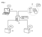
- FIG. 1 is a diagram showing a configuration of the entire PLC system in the present embodiment.
- the PLC system includes a PC (Personal Computer) 10, a DB (Database) server 20, a PLC 30, and a switching hub 40.
- the PC 10 is an information processing apparatus for a user to create a user program that is operated by the PLC 30.
- the DB server 20 is a server that functions as a DBMS (database management system) in order to manage a database.
- DBMS database management system
- the user program is created by the PLC 30 user.
- the user can create a program (source program) including an instruction to access the database by operating the PC 10.
- the PC 10 converts the source program into a format that can be executed by the PLC 30, and transmits the converted user program to the PLC 30.
- the PLC 30 executes the user program and can access the DB server 20 in accordance with an access command included in the user program.
- the PLC 30 is connected to the switching hub 40 and is connected to the PC 10 and the DB server 20 via the switching hub 40.
- the PLC 30 accepts sensor output and the like from the outside, and accumulates data.
- the PLC 30 transmits the accumulated data to the DB server 20 by processing of a DB access processing program 35 described later.
- FIG. 1 an example in which the PLC system includes a plurality of PLCs 30 is illustrated, and the main configurations of the PLCs 30 are the same.
- the switching hub 40 is connected to a plurality of devices such as the PC 10 and transfers data transmitted / received between the devices.
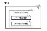
- FIG. 2 is a block diagram illustrating functions of the PC 10.
- the PC 10 is a computer system (information processing apparatus) including an MCU (Micro Control Unit), a ROM (Read Only Memory), a RAM (Random Access Memory), and the like. As shown in FIG. 2, the PC 10 exhibits the function of the programming tool 12.
- the programming tool 12 is a program that causes the PC 10 to exhibit a function for a user to create a user program for operating the PLC 30.
- the programming tool 12 includes functions of a data type definition unit 14 and a programming function 16.
- the user program created by the user using the programming tool 12 is transmitted to the PLC 30 and executed by the PLC 30.
- the user program includes structure type variables.
- the data type definition unit 14 is software for defining a structure type.
- a structure type is composed of a structure tag name and one or more member names.
- the data type definition unit 14 defines structure tag names, member names of these structures, and their data types. For example, in order to indicate each index used in production management at a factory or the like, the data type definition unit 14 sets the structure tag name to “ProductionTable”, and each member of the structure indicates the name of the product to be produced.
- the data type definition unit 14 defines the structure type in this way, and generates definition information 32 indicating the definition content.
- the programming function 16 is software for supporting user program creation. The PC 10 exhibits the functions of the data type definition unit 14 and the programming function 16 by executing these software on the PC 10.
- FIG. 3 is a block diagram showing functions of the DB server 20.
- the DB server 20 is a computer system including a large-capacity storage device.
- the DB server 20 exhibits the function of the DBMS 22 that manages reading and writing to the database.
- the DBMS 22 includes a DB 24 that functions as a database.
- the DB 24 holds a plurality of database tables 26.
- FIG. 4 is a block diagram showing functions of the PLC 30.
- the PLC 30 is a computer system and periodically executes a user program.
- the PLC 30 reads and writes information in the memory area in the PLC 30 and sequentially executes instructions indicated in the user program.
- the PLC 30 has an input / output function, receives data from outside the PLC 30 such as sensor output, and accumulates the data.
- the PLC 30 transmits the accumulated data to the DB server 20.
- each function of the PLC 30 includes an OS 31, a system program 33, a user program 38, and definition information 32.
- the OS 31 is designed according to the computer architecture of the PLC 30 and provides a basic execution environment for a microprocessor (not shown) to execute the system program 33 and the user program 38.
- the system program 33 is a software group for providing basic functions as the PLC 30, operates on the OS 31, and exhibits functions such as control of a ladder program.
- the system program 33 includes a sequence command program 34, a DB access processing program 35, an input / output processing program 36, and a scheduler 37.
- the sequence instruction program 34 sequentially executes instructions of the user program 38 while reading / writing information in the memory area in the PLC 30.
- the DB access processing program 35 is called when the sequence command program 34 executes the user program 38, and executes processing for the user program 38 to access the DB server 20, for example, processing such as generation of an SQL statement. .
- the input / output processing program 36 controls data input to and output from the PLC 30 by a plurality of input / output functions provided in the PLC 30. Each input / output function is assigned to a memory address. Data held in the memory corresponding to each input / output function is periodically exchanged with data outside the PLC 30 at a time.
- the scheduler 37 controls the execution of the sequence instruction program 34, the DB access processing program 35, and the input / output processing program 36.
- the user program 38 is created on the PC 10 by the user and held in the memory of the PLC 30. As shown in FIG. 4, the user program 38 and the sequence command program 34 constitute a control program 39. That is, the sequence command program 34 reads the user program 38 and executes the commands in order, thereby causing the PLC 30 to execute a control operation desired by the user.
- the definition information 32 is information indicating the definition of a structure type variable included in the user program 38, and defines a structure tag name, each member name included in the structure, and their data types.
- FIG. 5 is a diagram showing the database table 26. As described above, the database table 26 is managed by the DBMS 22 of the DB server 20.
- the database table 26 includes a table name 51 indicating the name of the table and table fields (Name 52, LotNo 53, SuccessCount 54, FailedCount 55,).
- the table name 51 is “Production Table”, and information about products is stored in the table.
- Name 52 indicates the name of the product.
- LotNo 53 indicates the lot number of the product.
- SuccessCount 54 indicates the number of product manufacturing successes, and FailedCount 55 indicates the number of product manufacturing failures.
- the outline of the operation in the first embodiment is as follows.
- the user creates a user program to be executed by the PLC 30 in the PC 10.
- the user creates a user program including a structure type variable.
- the PLC 30 receives the user program and the definition information 32 from the PC 10 and stores them.
- the sequence instruction program 34 sequentially executes the instructions of the user program 38, and extracts the value of each member of the structure type variable from the memory by executing the instructions of the user program 38.
- the sequence instruction program 34 passes processing to the DB access processing program 35 in response to an instruction for calling the DB access processing program 35.
- the DB access processing program 35 analyzes the definition shown in the definition information 32 of the user program 38, and the data of the structure type variable extracted by the execution of the data included in the user program 38 or the instruction of the user program 38.
- An SQL statement for accessing the DB server 20 is generated using the value of each member.
- the DB access processing program 35 executes the SQL statement by transmitting the generated SQL statement to the DB server 20 (the DB server 20 executes the SQL statement).
- the data type definition unit 14 of the programming tool 12 uses the structure tag name and member name and the data type of each member as the table name and field name of the database table 26 held in the DB server 20.
- the structure tag name corresponds to the table name
- the member name corresponds to the field name.
- the DB access processing program 35 can create an SQL statement using the structure tag name included in the definition information 32 as the table name as it is.
- the structure tag name defining the structure may be associated with the table name of the database table 26.
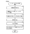
- FIG. 6 is a flowchart showing a process in which the DB access processing program 35 creates and executes an SQL statement.
- step S70 the DB access processing program 35 reads the definition information 32.
- step S72 the DB access processing program 35 extracts a member name with reference to the structure definition indicated in the definition information 32, and uses the extracted member name as a field name for operating the DB 24.
- step S74 the DB access processing program 35 extracts the structure tag name of the structure definition shown in the definition information 32, and uses the extracted structure tag name as the table name for operating the DB 24.
- step S76 the DB access processing program 35 reads the value of each member of the structure extracted by the execution of the user program 38.
- step S78 the DB access processing program 35 associates the field name acquired in step S72 with the value read in step S76, and generates an SQL statement using the table name acquired in step S74. To do.
- step S80 the DB access processing program 35 operates the DB 24 of the DB server 20 by transmitting the generated SQL statement to the DB server 20.
- a user who creates a user program for controlling the PLC 30 can access the DBMS 22 without writing a SQL statement for operating the database. For example, even a user who is unfamiliar with database operation can create a user program for accessing the database without learning the SQL concept for database operation.
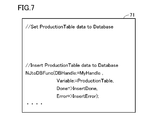
- FIG. 7 is a diagram illustrating an example of a user program.
- the user performs programming using a structure-type data structure.
- the variable name of the structure type variable is “ProductionTable”.
- the value of each member is extracted by executing the user program 71 of FIG.
- the value of the member “Name” is “Product1”
- the value of the member “LotNo” is “100”
- the value of the member “SuccessCount” is “49”
- the value of the member “FailedCount” is “ 1 ”is extracted from the memory of the PLC 30, and the SQL statement shown in FIG. 8 is created and transmitted from the PLC 30 to the DB server 20.
- the database is updated.
- NJtoDBFunc refers to a library (a library for accessing the DBMS 22 by the DB access processing program 35) prepared in advance in the sequence instruction program 34, and the PLC 30 accesses the DBMS 22 by the DB access processing program 35.
- Instructions to do “DBHandle” indicates a handle when the PLC 30 connects to the DBMS 22. The handle is set at the initial stage of connection to the DBMS 22 by the user program 38.
- “Variable” indicates a variable name of a structure type variable whose value is to be passed from the PLC 30 to the DB server 20 in this program (“ProductionTable” in the example of FIG. 7).
- “Done” and “Error” are output instructions, and indicate a state in which the instruction is completed.
- FIG. 8 is a diagram illustrating an example of an SQL sentence.
- FIG. 8 corresponds to the user program 71 of FIG.
- step S72 and step S74 the table name and field name to be accessed by the PLC 30 are extracted from each database table 26 held by the DB server 20.
- step S76 the DB access processing program 35 analyzes the lexical of each command of the user program 71 and reads the database value from the memory. As shown in the SQL statement 81 of FIG. 8, the SQL statement for updating the value of each field in the table name “ProductionTable” is generated by the DB access processing program 35.
- FIG. 8 shows the case where data is added to the database
- the program 35 operates the database by generating these SQL statements and sending them to the DB server 20.
- languages that manipulate data such as Insert and Select, DML (Data Manipulation Language), DDL (Data Definition Language), and the like can also be used.
- the DB access processing program 35 uses the structure tag name included in the definition information 32 as a table name for accessing the DBMS 22 as it is, and the member name included in the definition information 32 as It was described as a field name.
- the DB access processing program 35 may convert the structure tag name and the member name included in the definition information 32 into a table name and a field name for accessing the DBMS 22 based on a predetermined conversion rule.
- the predetermined conversion rule is, for example, a rule for converting a structure tag name or a member name of a structure into a character string that allows access to the DBMS 22. For example, (i) a part of a structure tag name or member name is omitted to obtain a table name or field name. (Ii) In DBMS 22, a character string prohibited from being used as a table name and field name is When included in the structure tag name or member name of the definition information 32, these character strings are deleted or corrected and used as a table name or the like.
- the DB access processing program 35 has been described as generating an SQL sentence including the value read in step S76 as shown in FIG. Not limited to this, the DB access processing program 35 first generates an SQL statement that does not include a value, transmits it to the DBMS 22 in advance, and then transmits the value to the DBMS 22 each time a value acquired periodically is acquired. Thus, the DBMS 22 may be operated.
- the DB access processing program 35 determines the field name and table name for operating the DB 24 by the processes up to step S70, step S72, and step S74, and determines the determined field name and table.
- An SQL statement that does not include a value is generated using the name.
- the item “VALUE” is blank (for example, VALUE (?,?,?,?))
- the DB access processing program 35 transmits an SQL sentence that does not include a value to the DBMS 22 in advance. Subsequently, the DB access processing program 35 transmits the value of the SQL sentence to the DBMS 22 based on the processing result of the user program 38.
- the value “('Product1”, 100, 49, 1) ” is transmitted from the PLC 30 to the DBMS 22 by the processing of the DB access processing program 35.
- the SQL statement is executed when the PLC 30 transmits the SQL statement not including the value and the value to the DBMS 22 by the processing of the DB access processing program 35.
- the PLC 30 uses the structure tag name and member name indicated in the definition information 32 as they are as the table name and field name based on the user program 38 and the definition information 32, or a predetermined conversion rule. It is assumed that the table name and field name are converted based on the above.
- mapping information indicating a conversion rule between the structure tag name and member name indicated in the definition information 32 and the table name and field name for the DB access processing program 35 to access the DBMS 22. 41 is held by the PLC 30.
- the DB access processing program 35 generates an SQL statement based on the mapping information 41 corresponding to the structure tag name.
- FIG. 9 is a functional block diagram showing the configuration of PLC 30 in the second embodiment. The difference from the first embodiment is that the PLC 30 holds the mapping information 41.
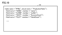
- FIG. 10 is a diagram illustrating an example of the mapping information 41. As shown in FIG. 10, the mapping information 41 associates structure tag names with table names for accessing the DBMS 22. The mapping information 41 associates each member name of the structure with each field name.
- the mapping information 41 is, for example, created in advance by the administrator of the DB server 20 and held by the PLC 30, or the table information and field information of the database table 26 are acquired by the PC 10 and defined by the data type definition unit 14.
- the administrator or the like may create a conversion rule for structure tag names and member names by the PC 10.
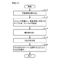
- FIG. 11 is a flowchart showing the operation of the DB access processing program 35 in the second embodiment.
- the PLC 30 receives the user program and the definition information 32 from the PC 10 and stores them.
- the sequence instruction program 34 sequentially executes the instructions of the user program 38, and extracts the value of each member of the structure type variable from the memory by executing the instructions of the user program 38.
- the sequence instruction program 34 passes processing to the DB access processing program 35 in response to an instruction for calling the DB access processing program 35.
- step S110 the DB access processing program 35 reads the definition information 32 of the user program 38.
- step S112 the DB access processing program 35 reads the structure tag name of the definition information 32 and the table name and field name corresponding to each member from the mapping information 41.
- step S114 the DB access processing program 35 reads the value of each member of the structure extracted by the execution of the user program 38.
- step S118 the DB access processing program 35 generates an SQL statement for accessing the DB server 20 using the table name and field name read in step S112 and the value read in step S114.
- step S120 the DB access processing program 35 executes the SQL statement by transmitting the generated SQL statement to the DB server 20.
- the mapping information 41 indicates the conversion rule between the definition information 32 and the table name and field name for accessing the DBMS 22, for example, characters that cannot be used as the table name and field name Even when the column is included in the structure tag name or member name
- the DB access processing program 35 can generate the SQL statement by referring to the mapping information 41. Further, in the DBMS 22, the DB access processing program 35 refers to the mapping information 41 even when the naming rule of the table name and the field name is difficult for the user (for example, the character string that the table name is difficult for humans to remember).
- the user can create the user program 38 using an easily understandable character string as the structure tag name or member name. It is also effective when the user wants to freely set a structure tag name or a member name, and the user can perform programming even if the user is not familiar with the SQL concept.
- the mapping information 41 has been described as being created in advance by the administrator of the DB server 20 and held by the PLC 30, for example.
- the user program 38 may include an instruction that the PLC 30 should generate the mapping information 41.
- the PC 10 includes a user program including a conversion rule between a structure data definition (structure tag name, member name, etc.) indicated in the definition information 32 and a table name and field name for the PLC 30 to access the DBMS 22. 38 is generated.
- This user program 38 includes an instruction for the PLC 30 to generate the mapping information 41.
- the sequence instruction program 34 executes the user program 38, generates the mapping information 41 according to the instruction to generate the conversion rule and mapping information 41 included in the user program 38, and generates the generated mapping information 41. Is stored in memory.
- the DB access processing program 35 generates an SQL statement by referring to the mapping information 41 held in the memory based on the structure type variable included in the user program 38 in the processing after the mapping information 41 is generated. This speeds up the process in which the PLC 30 generates the SQL statement.
- the PC 10 generates the definition information 32 and the user program in response to a user input operation, and transmits the generated definition information 32 and the user program to the PLC 30 from the PC 10 respectively.
- the user program may include the definition information 32.
- the PC 10 generates a user program including the definition information 32 and transmits the generated user program to the PLC 30.
Landscapes
- Engineering & Computer Science (AREA)
- Databases & Information Systems (AREA)
- Theoretical Computer Science (AREA)
- Physics & Mathematics (AREA)
- General Physics & Mathematics (AREA)
- Data Mining & Analysis (AREA)
- General Engineering & Computer Science (AREA)
- Automation & Control Theory (AREA)
- Computational Linguistics (AREA)
- Programmable Controllers (AREA)
- Information Retrieval, Db Structures And Fs Structures Therefor (AREA)
- Stored Programmes (AREA)
Abstract
Priority Applications (4)
| Application Number | Priority Date | Filing Date | Title |
|---|---|---|---|
| CN201380032494.5A CN104395845B (zh) | 2012-06-22 | 2013-06-21 | 控制装置 |
| EP13807001.6A EP2866108A4 (fr) | 2012-06-22 | 2013-06-21 | Dispositif de commande |
| US14/405,980 US10061809B2 (en) | 2012-06-22 | 2013-06-21 | Control device |
| JP2014521521A JP6065008B2 (ja) | 2012-06-22 | 2013-06-21 | 制御装置 |
Applications Claiming Priority (2)
| Application Number | Priority Date | Filing Date | Title |
|---|---|---|---|
| JP2012141378 | 2012-06-22 | ||
| JP2012-141378 | 2012-06-22 |
Publications (1)
| Publication Number | Publication Date |
|---|---|
| WO2013191275A1 true WO2013191275A1 (fr) | 2013-12-27 |
Family
ID=49768866
Family Applications (1)
| Application Number | Title | Priority Date | Filing Date |
|---|---|---|---|
| PCT/JP2013/067088 WO2013191275A1 (fr) | 2012-06-22 | 2013-06-21 | Dispositif de commande |
Country Status (5)
| Country | Link |
|---|---|
| US (1) | US10061809B2 (fr) |
| EP (1) | EP2866108A4 (fr) |
| JP (1) | JP6065008B2 (fr) |
| CN (1) | CN104395845B (fr) |
| WO (1) | WO2013191275A1 (fr) |
Cited By (7)
| Publication number | Priority date | Publication date | Assignee | Title |
|---|---|---|---|---|
| WO2015162794A1 (fr) * | 2014-04-25 | 2015-10-29 | 三菱電機株式会社 | Dispositif d'aide à la liaison d'informations et programme d'aide à la liaison d'informations |
| KR20160083284A (ko) * | 2014-12-30 | 2016-07-12 | 주식회사 포스코아이씨티 | 이기종 데이터베이스를 지원하는 제어기 관리 스테이션 및 이를 포함하는 제어 시스템 |
| EP3076309A1 (fr) | 2015-03-31 | 2016-10-05 | Omron Corporation | Contrôleur à logique programmable, appareil de collecte de données, procédé d'accès à une base de données et programme d'accès à une base de données |
| WO2018193503A1 (fr) * | 2017-04-17 | 2018-10-25 | 三菱電機株式会社 | Dispositif de création de programme |
| WO2019176486A1 (fr) * | 2018-03-15 | 2019-09-19 | オムロン株式会社 | Système de commande, organe de commande et procédé de commande |
| WO2019176487A1 (fr) * | 2018-03-15 | 2019-09-19 | オムロン株式会社 | Dispositif de commande, procédé de commande et programme de commande |
| JP2020144753A (ja) * | 2019-03-08 | 2020-09-10 | オムロン株式会社 | 制御システム、情報処理装置、および情報処理プログラム |
Families Citing this family (5)
| Publication number | Priority date | Publication date | Assignee | Title |
|---|---|---|---|---|
| EP3118696B1 (fr) * | 2015-04-06 | 2020-07-22 | Mitsubishi Electric Corporation | Système d'automate programmable |
| US10169351B2 (en) | 2015-08-19 | 2019-01-01 | International Business Machines Corporation | Merging directory information from a user directory to a common directory |
| WO2019046752A1 (fr) * | 2017-08-31 | 2019-03-07 | Schneider Electric Software, Llc | Réseau de données d'indexation d'objets |
| CN109885532A (zh) * | 2019-02-11 | 2019-06-14 | 中国银行股份有限公司 | 一种交易数据标准化方法和装置 |
| CN112015831A (zh) * | 2020-09-09 | 2020-12-01 | 深圳市绿联科技有限公司 | 基于c语言对关系型数据库进行操作的方法、装置及设备 |
Citations (9)
| Publication number | Priority date | Publication date | Assignee | Title |
|---|---|---|---|---|
| JP2001034513A (ja) * | 1999-07-19 | 2001-02-09 | Hitachi Ltd | データ変換方法および装置並びにデータ変換プログラムを格納した記憶媒体 |
| JP2002023812A (ja) * | 2000-07-05 | 2002-01-25 | Mitsubishi Materials Corp | 自動制御システムおよび自動制御方法 |
| JP2002099561A (ja) * | 2000-09-21 | 2002-04-05 | Toshiba Corp | データ変換方法およびデータ変換システム並びに記憶媒体 |
| JP2002149652A (ja) * | 2000-11-07 | 2002-05-24 | Hitachi Ltd | データベース検索処理方法及びその実施装置並びにその処理プログラムを記録した記録媒体 |
| JP2003091530A (ja) * | 2001-09-17 | 2003-03-28 | Toshiba Corp | 構造化データ変換方法、構造化データ変換プログラム、構造化データ変換装置 |
| JP2004302849A (ja) * | 2003-03-31 | 2004-10-28 | Mitsubishi Electric Corp | Faコントローラ |
| JP2007080286A (ja) | 2006-11-13 | 2007-03-29 | Omron Corp | データ収集装置 |
| JP2008083872A (ja) * | 2006-09-26 | 2008-04-10 | Fuji Electric Fa Components & Systems Co Ltd | シーケンスプログラム変換装置、プログラマブルコントローラのプログラミング装置、および、プログラマブルコントローラ |
| JP2012108642A (ja) * | 2010-11-16 | 2012-06-07 | Fuji Electric Co Ltd | データ収集システム、データ収集システムの異常要因判定方法 |
Family Cites Families (11)
| Publication number | Priority date | Publication date | Assignee | Title |
|---|---|---|---|---|
| US6735594B1 (en) | 2000-06-23 | 2004-05-11 | International Business Machines Corporation | Transparent parameter marker support for a relational database over a network |
| US7467018B1 (en) | 2002-11-18 | 2008-12-16 | Rockwell Automation Technologies, Inc. | Embedded database systems and methods in an industrial controller environment |
| US20060026193A1 (en) * | 2004-08-02 | 2006-02-02 | Rockwell Software, Inc. | Dynamic schema for unified plant model |
| JP2006164090A (ja) | 2004-12-10 | 2006-06-22 | Hitachi Ltd | データベース操作プログラムの自動生成装置 |
| US7565351B1 (en) | 2005-03-14 | 2009-07-21 | Rockwell Automation Technologies, Inc. | Automation device data interface |
| US8065666B2 (en) * | 2006-06-02 | 2011-11-22 | Rockwell Automation Technologies, Inc. | Change management methodologies for industrial automation and information systems |
| DE102006046643A1 (de) | 2006-09-29 | 2008-04-03 | Phoenix Contact Gmbh & Co. Kg | Speicherprogrammierbare Steuereinrichtung mit integriertem Datenbanktreiber |
| CN100456237C (zh) * | 2007-01-31 | 2009-01-28 | 华为技术有限公司 | 数据库访问方法和装置 |
| US7853336B2 (en) * | 2007-02-27 | 2010-12-14 | Rockwell Automation Technologies, Inc. | Dynamic versioning utilizing multiple controller engine instances to limit complications |
| CN101714087A (zh) * | 2009-12-15 | 2010-05-26 | 四川长虹电器股份有限公司 | C语言结构体至关系数据库表的映射系统及映射方法 |
| JP6201298B2 (ja) | 2012-11-14 | 2017-09-27 | オムロン株式会社 | コントローラおよびプログラム |
-
2013
- 2013-06-21 CN CN201380032494.5A patent/CN104395845B/zh active Active
- 2013-06-21 JP JP2014521521A patent/JP6065008B2/ja active Active
- 2013-06-21 US US14/405,980 patent/US10061809B2/en active Active
- 2013-06-21 WO PCT/JP2013/067088 patent/WO2013191275A1/fr active Application Filing
- 2013-06-21 EP EP13807001.6A patent/EP2866108A4/fr not_active Withdrawn
Patent Citations (9)
| Publication number | Priority date | Publication date | Assignee | Title |
|---|---|---|---|---|
| JP2001034513A (ja) * | 1999-07-19 | 2001-02-09 | Hitachi Ltd | データ変換方法および装置並びにデータ変換プログラムを格納した記憶媒体 |
| JP2002023812A (ja) * | 2000-07-05 | 2002-01-25 | Mitsubishi Materials Corp | 自動制御システムおよび自動制御方法 |
| JP2002099561A (ja) * | 2000-09-21 | 2002-04-05 | Toshiba Corp | データ変換方法およびデータ変換システム並びに記憶媒体 |
| JP2002149652A (ja) * | 2000-11-07 | 2002-05-24 | Hitachi Ltd | データベース検索処理方法及びその実施装置並びにその処理プログラムを記録した記録媒体 |
| JP2003091530A (ja) * | 2001-09-17 | 2003-03-28 | Toshiba Corp | 構造化データ変換方法、構造化データ変換プログラム、構造化データ変換装置 |
| JP2004302849A (ja) * | 2003-03-31 | 2004-10-28 | Mitsubishi Electric Corp | Faコントローラ |
| JP2008083872A (ja) * | 2006-09-26 | 2008-04-10 | Fuji Electric Fa Components & Systems Co Ltd | シーケンスプログラム変換装置、プログラマブルコントローラのプログラミング装置、および、プログラマブルコントローラ |
| JP2007080286A (ja) | 2006-11-13 | 2007-03-29 | Omron Corp | データ収集装置 |
| JP2012108642A (ja) * | 2010-11-16 | 2012-06-07 | Fuji Electric Co Ltd | データ収集システム、データ収集システムの異常要因判定方法 |
Non-Patent Citations (1)
| Title |
|---|
| See also references of EP2866108A4 * |
Cited By (21)
| Publication number | Priority date | Publication date | Assignee | Title |
|---|---|---|---|---|
| CN105393181B (zh) * | 2014-04-25 | 2017-06-09 | 三菱电机株式会社 | 信息协同辅助装置、信息协同辅助程序 |
| KR20160020569A (ko) * | 2014-04-25 | 2016-02-23 | 미쓰비시덴키 가부시키가이샤 | 정보 제휴 지원 장치, 정보 제휴 지원 프로그램 |
| JP5875737B1 (ja) * | 2014-04-25 | 2016-03-02 | 三菱電機株式会社 | 情報連携支援装置、情報連携支援プログラム |
| CN105393181A (zh) * | 2014-04-25 | 2016-03-09 | 三菱电机株式会社 | 信息协同辅助装置、信息协同辅助程序 |
| WO2015162794A1 (fr) * | 2014-04-25 | 2015-10-29 | 三菱電機株式会社 | Dispositif d'aide à la liaison d'informations et programme d'aide à la liaison d'informations |
| KR101665300B1 (ko) | 2014-04-25 | 2016-10-11 | 미쓰비시덴키 가부시키가이샤 | 정보 제휴 지원 장치 및 정보 제휴 지원 프로그램이 기록된 기록매체 |
| US9841754B2 (en) | 2014-04-25 | 2017-12-12 | Mitsubishi Electric Corporation | Information-linkage supporting apparatus and information-linkage supporting program |
| KR20160083284A (ko) * | 2014-12-30 | 2016-07-12 | 주식회사 포스코아이씨티 | 이기종 데이터베이스를 지원하는 제어기 관리 스테이션 및 이를 포함하는 제어 시스템 |
| KR101704145B1 (ko) | 2014-12-30 | 2017-02-08 | 주식회사 포스코아이씨티 | 이기종 데이터베이스를 지원하는 제어기 관리 스테이션 및 이를 포함하는 제어 시스템 |
| EP3076309A1 (fr) | 2015-03-31 | 2016-10-05 | Omron Corporation | Contrôleur à logique programmable, appareil de collecte de données, procédé d'accès à une base de données et programme d'accès à une base de données |
| JP2016194808A (ja) * | 2015-03-31 | 2016-11-17 | オムロン株式会社 | プログラマブルロジックコントローラ、データ収集装置、データベースアクセス方法およびデータベースアクセスプログラム |
| WO2018193503A1 (fr) * | 2017-04-17 | 2018-10-25 | 三菱電機株式会社 | Dispositif de création de programme |
| CN109478051A (zh) * | 2017-04-17 | 2019-03-15 | 三菱电机株式会社 | 程序创建装置 |
| WO2019176486A1 (fr) * | 2018-03-15 | 2019-09-19 | オムロン株式会社 | Système de commande, organe de commande et procédé de commande |
| WO2019176487A1 (fr) * | 2018-03-15 | 2019-09-19 | オムロン株式会社 | Dispositif de commande, procédé de commande et programme de commande |
| US11281650B2 (en) | 2018-03-15 | 2022-03-22 | Omron Corporation | Control system, controller, and control method |
| US11334550B2 (en) | 2018-03-15 | 2022-05-17 | Omron Corporation | Controller, control method, and control program for SQL statement generation in a factory automation database |
| JP2020144753A (ja) * | 2019-03-08 | 2020-09-10 | オムロン株式会社 | 制御システム、情報処理装置、および情報処理プログラム |
| WO2020184061A1 (fr) * | 2019-03-08 | 2020-09-17 | オムロン株式会社 | Système de commande, dispositif de traitement d'informations et programme de traitement d'informations |
| CN113518981A (zh) * | 2019-03-08 | 2021-10-19 | 欧姆龙株式会社 | 控制系统、信息处理装置以及信息处理程序 |
| JP7014199B2 (ja) | 2019-03-08 | 2022-02-01 | オムロン株式会社 | 制御システム、情報処理装置、および情報処理プログラム |
Also Published As
| Publication number | Publication date |
|---|---|
| JPWO2013191275A1 (ja) | 2016-05-26 |
| JP6065008B2 (ja) | 2017-01-25 |
| CN104395845B (zh) | 2017-07-25 |
| EP2866108A1 (fr) | 2015-04-29 |
| EP2866108A4 (fr) | 2015-11-04 |
| US20150254305A1 (en) | 2015-09-10 |
| US10061809B2 (en) | 2018-08-28 |
| CN104395845A (zh) | 2015-03-04 |
Similar Documents
| Publication | Publication Date | Title |
|---|---|---|
| JP6065008B2 (ja) | 制御装置 | |
| US10209695B2 (en) | Method and a system for replacing and commissioning of a field device | |
| CN107179753B (zh) | 来自控制器程序文件的自动化控制系统点配置 | |
| US9823907B2 (en) | Extensible device object model | |
| US20220058502A1 (en) | Gateway and method for transforming a description of an industrial process equipment into a data information model | |
| US11385613B2 (en) | Process image within controllers enabling visibility and accessibility of real world objects | |
| US20120290539A1 (en) | Methods and apparatus for a file system on a programmable logic controller | |
| US8032232B2 (en) | Natively retaining project documentation in a controller | |
| EP3042254A1 (fr) | Systèmes et procédés destinés à virtualiser un automate programmable | |
| CN112363695A (zh) | Pmml文件及其运行时环境与工业软件的集成方法 | |
| CN112363694B (zh) | Fmu文件及求解器运行环境与工业软件的集成方法 | |
| JP6370503B1 (ja) | プログラム作成装置 | |
| Weigand et al. | Creating Virtual Knowledge Graphs from Software-Internal Data | |
| JP2006294011A (ja) | 制御プログラム開発支援装置 | |
| US8706751B2 (en) | Method for providing a user interface driven by database tables | |
| Schachinger et al. | Model-driven integration of building automation systems into Web service gateways | |
| Martin et al. | Integrated design of Human-Machine Interfaces for production plants | |
| US20120011157A1 (en) | Method and system for inferencing taxonomy topic concept objects using a metamodel instance model | |
| Runde et al. | EDDL and semantic web—From field device integration (FDI) to Future Device Management (FDM) | |
| CN112020684B (zh) | 信息处理装置、系统构建辅助方法及存储有系统构建辅助程序的非易失性存储装置 | |
| JP2006079277A (ja) | 構造化文書データ変換装置及び方法 | |
| US20240103478A1 (en) | Validation Logic for OPC UA Connected Devices | |
| US20240103826A1 (en) | Collaborative work on translations in industrial system projects | |
| Genter et al. | Software tool for modeling, simulation and real-time implementation of Petri net-based supervisors | |
| WO2019221234A1 (fr) | Dispositif de génération de logique de conversion, système d'exécution de procédé http, procédé d'exécution de procédé http et programme de génération de logique de conversion |
Legal Events
| Date | Code | Title | Description |
|---|---|---|---|
| 121 | Ep: the epo has been informed by wipo that ep was designated in this application |
Ref document number: 13807001 Country of ref document: EP Kind code of ref document: A1 |
|
| WWE | Wipo information: entry into national phase |
Ref document number: 2013807001 Country of ref document: EP |
|
| ENP | Entry into the national phase |
Ref document number: 2014521521 Country of ref document: JP Kind code of ref document: A |
|
| NENP | Non-entry into the national phase |
Ref country code: DE |
|
| WWE | Wipo information: entry into national phase |
Ref document number: 14405980 Country of ref document: US |